WO2021192254A1 - Procédé et système de recyclage de verre en feuilles - Google Patents
Procédé et système de recyclage de verre en feuilles Download PDFInfo
- Publication number
- WO2021192254A1 WO2021192254A1 PCT/JP2020/014135 JP2020014135W WO2021192254A1 WO 2021192254 A1 WO2021192254 A1 WO 2021192254A1 JP 2020014135 W JP2020014135 W JP 2020014135W WO 2021192254 A1 WO2021192254 A1 WO 2021192254A1
- Authority
- WO
- WIPO (PCT)
- Prior art keywords
- glass
- crushing
- cullet
- crusher
- flat
- Prior art date
- Legal status (The legal status is an assumption and is not a legal conclusion. Google has not performed a legal analysis and makes no representation as to the accuracy of the status listed.)
- Ceased
Links
Images








Classifications
-
- B—PERFORMING OPERATIONS; TRANSPORTING
- B09—DISPOSAL OF SOLID WASTE; RECLAMATION OF CONTAMINATED SOIL
- B09B—DISPOSAL OF SOLID WASTE NOT OTHERWISE PROVIDED FOR
- B09B3/00—Destroying solid waste or transforming solid waste into something useful or harmless
- B09B3/30—Destroying solid waste or transforming solid waste into something useful or harmless involving mechanical treatment
- B09B3/35—Shredding, crushing or cutting
-
- B—PERFORMING OPERATIONS; TRANSPORTING
- B02—CRUSHING, PULVERISING, OR DISINTEGRATING; PREPARATORY TREATMENT OF GRAIN FOR MILLING
- B02C—CRUSHING, PULVERISING, OR DISINTEGRATING IN GENERAL; MILLING GRAIN
- B02C19/00—Other disintegrating devices or methods
-
- B—PERFORMING OPERATIONS; TRANSPORTING
- B02—CRUSHING, PULVERISING, OR DISINTEGRATING; PREPARATORY TREATMENT OF GRAIN FOR MILLING
- B02C—CRUSHING, PULVERISING, OR DISINTEGRATING IN GENERAL; MILLING GRAIN
- B02C4/00—Crushing or disintegrating by roller mills
- B02C4/02—Crushing or disintegrating by roller mills with two or more rollers
- B02C4/08—Crushing or disintegrating by roller mills with two or more rollers with co-operating corrugated or toothed crushing-rollers
-
- Y—GENERAL TAGGING OF NEW TECHNOLOGICAL DEVELOPMENTS; GENERAL TAGGING OF CROSS-SECTIONAL TECHNOLOGIES SPANNING OVER SEVERAL SECTIONS OF THE IPC; TECHNICAL SUBJECTS COVERED BY FORMER USPC CROSS-REFERENCE ART COLLECTIONS [XRACs] AND DIGESTS
- Y02—TECHNOLOGIES OR APPLICATIONS FOR MITIGATION OR ADAPTATION AGAINST CLIMATE CHANGE
- Y02W—CLIMATE CHANGE MITIGATION TECHNOLOGIES RELATED TO WASTEWATER TREATMENT OR WASTE MANAGEMENT
- Y02W30/00—Technologies for solid waste management
- Y02W30/20—Waste processing or separation
-
- Y—GENERAL TAGGING OF NEW TECHNOLOGICAL DEVELOPMENTS; GENERAL TAGGING OF CROSS-SECTIONAL TECHNOLOGIES SPANNING OVER SEVERAL SECTIONS OF THE IPC; TECHNICAL SUBJECTS COVERED BY FORMER USPC CROSS-REFERENCE ART COLLECTIONS [XRACs] AND DIGESTS
- Y02—TECHNOLOGIES OR APPLICATIONS FOR MITIGATION OR ADAPTATION AGAINST CLIMATE CHANGE
- Y02W—CLIMATE CHANGE MITIGATION TECHNOLOGIES RELATED TO WASTEWATER TREATMENT OR WASTE MANAGEMENT
- Y02W30/00—Technologies for solid waste management
- Y02W30/50—Reuse, recycling or recovery technologies
- Y02W30/60—Glass recycling
Definitions
- the present invention relates to a recycling system and a recycling method for recycling flat glass used as solar panel glass, automobile glass, window glass, amusement machine glass, and the like.
- flat glass is used in various fields as solar panel glass, automobile glass, window glass, amusement machine glass, etc., but its resource recovery rate is low, and the discarded flat glass is usually shredder dust. It is often buried in the ground.
- the flat glass to be disposed of becomes a sharp glass cullet when broken, and the shape is irregular and various in size, so it is difficult to handle and it is not suitable for recycling.
- the conventional glass recycling method is a glass recycling method for reusing waste glass with a sheet or a film, in which the waste glass is crushed and the crushed glass pieces are divided into at least two glass pieces having different sizes. Sifted and collected a part of the screened glass piece as recycled glass, wind-sorted the other part of the screened glass piece and the sheet or film piece, and wind-sorted the glass piece.
- a recycling method is known in which the glass is collected as recycled glass.
- glass components are separated by ore by utilizing the difference in crushing strength between aggregates and glass components with respect to aggregates and glass components with almost no difference in specific gravity.
- a method is known in which the aggregate is pulverized from the aggregate, classified, and the aggregate is recovered.
- An object of the present invention is to provide a method and a recycling system for flat glass, which can be dried to have an appropriate particle size and can easily make the particle size constant.
- the present invention according to claim 1 comprises a plate glass crushing step of crushing a plate glass to obtain a glass cullet, and a glass cullet crushing step of crushing the glass cullet obtained in the step into sandy glass powder. Is.
- the present invention according to claim 2 further includes a sandy glass powder sieving step for sieving the sandy glass powder obtained in the glass cullet crushing step with respect to the plate glass recycling method according to claim 1. It is a feature.
- the present invention according to claim 3 relates to the method for recycling flat glass according to claim 1 or 2, further, in a glass powder sieving step, sandy glass powder larger than a predetermined particle size is returned to a glass cullet crushing step and re-processed. It is characterized by having a glass powder crushing step for crushing.
- the present invention according to claim 4 is characterized in that the outer shape of the glass cullet in the plate glass crushing step is 15 mm or less in the method for recycling the plate glass according to any one of claims 1 to 3. do.
- the particle size of the sandy glass powder obtained in the glass cullet crushing step is 0.3 in the method for recycling the flat glass according to any one of the first to fourth aspects. It is characterized in that it is within the range of about 5 mm.
- the present invention according to claim 6 relates to the method for recycling flat glass according to any one of claims 1 to 5, further, in one or both steps of a flat glass crushing step and a glass cullet crushing step. It is characterized by having a glass dust collecting step for collecting the generated glass dust.
- the present invention according to claim 7 is a glass crusher provided with a pair of crushing rolls in which the plate glass crushing step crushes the plate glass according to the method for recycling the plate glass according to any one of claims 1 to 6. It is characterized by being done by.
- the present invention according to claim 8 relates to the method for recycling flat glass according to any one of claims 1 to 7, wherein the glass cullet pulverization step collides and pulverizes the glass cullet in the drum portion. This is done by a glass crusher equipped with a glass crusher and a preduster equipped with a reflector for colliding and crushing sandy glass powder scattered and conveyed by the wind pressure of the crushing rotor via a transport pipe extending from the glass crusher. It is a feature.
- the present invention according to claim 9 relates to the method for recycling a flat glass according to any one of claims 1 to 8, wherein the flat glass is a solar panel glass and a step of crushing the flat glass in the solar panel. It is characterized by later eliminating the solar panel module and crushing only the glass cullet.
- the present invention according to claim 10 is a flat glass recycling system used in the flat glass recycling method according to any one of claims 1 to 9, wherein the flat glass is crushed to obtain a glass cullet.
- a plate glass crusher that executes the process and a glass cullet crusher that executes a glass cullet crushing step of crushing the glass cullet obtained in the process into sandy glass powder are provided.
- the upper roll and the lower roll are provided with square ridges having a cross section at predetermined intervals in a direction orthogonal to the axial direction thereof, and the ridges of the upper roll and the lower roll are arranged alternately. It is installed.
- the present invention according to claim 11 is characterized in that, in the plate glass recycling system according to claim 10, the ridges of the upper and lower rolls of the plate glass crusher have a trapezoidal cross section narrowing toward the tip side. ..
- the glass crushing device in the flat glass recycling system according to the tenth or eleventh aspect, includes a drum portion having a crushing rotor for crushing a pre-crushed glass cullet. It has a machine, a substantially linear transport pipe that extends diagonally upward from the crusher and guides crushed sandy glass powder in the drum portion, and a container-shaped preduster into which the upper end of the transport pipe is inserted.
- the preduster is provided with a reflector that faces the upper end of the transport pipe and guides the sandy glass powder discharged from the upper end of the transport pipe into the preduster.
- the present invention according to claim 13 is the glass dust recycling system according to any one of claims 10 to 12, and further, glass dust that collects glass dust in one or both of a flat glass crusher and a preduster. It is characterized by being equipped with a collector.
- flat glass used as solar panel glass, automobile glass, window glass, amusement machine glass, etc. can be finally made into fine sandy glass powder having a certain particle size. Therefore, the recycling of flat glass is highly realized as compared with the conventional case.
- the flat glass recycling method according to the present invention can be performed by a dry method, there is no problem of waste liquid treatment unlike the conventional wet specific gravity sorter, and the problem of environmental load in the recycling work is also solved.
- the finally obtained sandy glass can be used as a road construction material or a decorative material, and can be expected to be used in a wide range of fields. ..
- a crusher main body having a pair of upper and lower plate glass crushing rolls composed of an upper roll and a lower roll facing each other, and holding rolls provided on the front side and the rear side of the upper roll, respectively, and a crusher main body.
- the upper roll and the lower roll are provided with roller conveyors on the front side and the rear side, respectively, and ridges having a rectangular cross section are provided around the upper roll and the lower roll at predetermined intervals in a direction orthogonal to the axial direction thereof.
- the glass crusher includes a crusher having a drum portion having a crushing rotor for crushing a glass cullet that has been crushed in advance, and sandy glass powder that extends diagonally upward from the crusher and is crushed in the drum portion. It has a substantially linear transport pipe for guiding the transport pipe and a container-shaped preduster into which the upper end of the transport pipe is inserted, and the preduster faces the upper end of the transport pipe and is from the upper end of the transport pipe.
- the plate glass recycling system according to claim 12 which includes a reflecting plate that guides the sandy glass powder to be discharged into the preduster, the various effects described above can be obtained in a superposed manner.
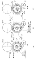
- FIG. 5 is a partially enlarged view of FIG. 5, which is an enlarged cross-sectional view showing a first crushed state of the plate glass by a vertical roll in a plate glass crusher.
- FIG. 5 is a partially enlarged view of FIG.
- FIG. 5 which is an enlarged cross-sectional view showing a second crushed state in which the plate glass is shifted by 1/2 pitch in the left-right direction together with the conveyor from the plate glass crushing position of FIG.
- FIG. 8 is an enlarged front view showing a partially cross-sectional view of the mounting state of the upper roll and the lower roll in FIG.
- It is a perspective view of the shifting device of a roller conveyor. It is a side view which shows the structure of the eccentric ring and the outer peripheral gear which affect the raising and lowering of a lower roll. It is a figure which shows the eccentric position of the lower roll by the eccentric ring of FIG.
- FIG. 1 It is an enlarged perspective view of the main part which shows the rotor mounting state in the crusher in the glass crushing apparatus which concerns on this embodiment. It is a perspective view which shows the relationship between a drum part and an inner lid. It is a perspective view which shows the opening and closing procedure of a door body after attaching the inner lid of FIG. It is a perspective view which shows the bearing state of the drive rotating shaft in a crusher. It is a perspective view which shows the interlocking structure of the drive rotation shaft of a crusher and an electric motor.
- the front, back, left, right, up and down are based on FIG. 2, the front side means the left side direction of FIG. 2, and the rear side means the right side direction of the same figure. Further, the left side means the front side direction of the drawing paper leaf of FIG. 2, and the right side means the back side direction of the drawing paper leaf of the same figure. Further, the upper side and the lower side refer to the upper side direction and the lower side direction in FIG.
- the plate glass recycling method according to the present invention includes a plate glass crushing step (S0001) in which the plate glass is crushed to obtain a glass cullet, and the glass cullet obtained in the step is crushed into sandy glass powder. It has a glass cullet crushing step (S0002), and further has a sandy glass powder sieving step (S0003) for sieving the sandy glass powder obtained in the glass cullet crushing step, if necessary.
- the glass dust collecting step (S0005) (S0006) for collecting the glass dust generated in one or both of the plate glass crushing step (S0001) and the glass cullet crushing step (S0002). Has.
- the outer shape of the glass cullet obtained in the plate glass crushing step (S0001) is about 15 mm or less, and the particle size of the sandy glass powder obtained in the glass cullet crushing step is within the range of 0.3 to 5 mm. be.
- the flat glass crushing step (S0001) is performed by a glass crusher 1 provided with a pair of crushing rolls 2A and 2B for crushing the flat glass.
- the crushing rotor 52 includes a crushing rotor 56 for colliding and crushing the glass cullet in the drum portion 53, and the crushing rotor 60 via a transport pipe 60 extending from the glass crusher 52. It is executed by the preduster 54 provided with the reflector 61 that collides and crushes the sandy glass powder scattered and conveyed by the wind pressure of 56.
- the flat glass crusher 1 that executes the flat glass crushing step (S0001) for crushing the flat glass to obtain a glass cullet, and the glass cullet obtained in the step are sanded glass powder.
- a flat glass recycling system including a glass crusher 51 that performs a glass cullet crushing step (S0002) to crush the glass.
- the plate glass crusher 1 includes a pair of upper and lower plate glass crushing rolls composed of an upper roll 2A and a lower roll 2B facing each other, and pressers provided on the front side and the rear side of the upper roll 2A, respectively. It has a crusher main body 10 having a roll 6 and roller conveyors 11A and 11B provided on the front side and the rear side of the crusher main body 10, respectively, and the upper roll 2A and the lower roll 2B are orthogonal to the axial direction thereof.
- the ridges 3A and 3B having a rectangular cross section are provided around at predetermined intervals in the direction, and the ridges 3A and 3B of the upper roll 2A and the lower roll 2B are arranged alternately.
- the glass crusher 51 extends obliquely upward from the crusher 52 having a drum portion 53 incorporating a crushing rotor 56 for crushing a glass cullet that has been crushed in advance, and the crusher 52.
- the preduster 54 has a substantially linear transport pipe 60 for guiding crushed sandy glass powder in the drum portion 53 and a container-shaped preduster 54 into which the upper end of the transport pipe 60 is inserted.
- a reflector 61 that faces the upper end of the transport pipe 60 and guides the sandy glass powder discharged from the upper end of the transport pipe 60 into the preduster 54 is provided.
- glass dust collectors 21 and 92 for collecting glass dust are attached to both the plate glass crusher 1 and the preduster 54.
- the flat glass SG mounted on the rear roller conveyor 16B in the flat glass crusher 1 has an upper roll 2A and a lower roll.
- the glass cullet GC crushed by 2B and crushed is carried from the roller conveyor 16A on the front side to the glass crusher 51 by the first belt conveyor BT1, and the glass cullet GC is crushed in the glass crusher 51 to be sandy glass.
- the sandy glass powder becomes powder, and the sandy glass powder enters the preduster 54 via the transport pipe 60 and collides with the reflector 61 in the predaster 54, so that the sandy glass powder is further crushed. NS. After that, the sandy glass is carried into the sieving machine 75 by the hopper 55.
- the sandy glass powder having a predetermined particle size (for example, 5 mm) or less in the sieving machine 75 is stored in a recovery container (not shown) as a final resource.
- the sandy glass powder larger than a predetermined particle size (for example, 5 mm) in the sieving machine 75 is placed on the second belt conveyor BT2 as a return conveyor and put into the glass crusher 52 again to further crush. Is done.
- the plate glass crusher 1 As shown in FIGS. 3 to 7, the plate glass crusher 1 according to the present embodiment has an upper roll 2A and a lower side facing each other in the left-right direction in the central portion.
- a crusher main body 10 having a pair of upper and lower flat glass crushing rolls including rolls 2B is provided, and roller conveyors 11A and 11B are installed on the front side and the rear side thereof, respectively.
- the crusher main body 10 includes a pair of upper and lower plate glass crushing rolls (made of steel) composed of an upper roll 2A and a lower roll 2B facing each other in the left-right direction, and the rolls 2A and 2B, respectively.
- the ridges 3A and 3B having a rectangular cross section and the concave grooves 4A having a predetermined depth formed between the ridges 3A and 3B having a predetermined interval P (pitch) in a direction orthogonal to the axial direction of the ridges 3A and 3B.
- the 4Bs are provided around each other, and the ridges 3A and 3B and the concave grooves 4A and 4B in the upper roll 2A and the lower roll 2B are arranged alternately.
- the ridges 3A and 3B have a trapezoidal cross section whose width narrows toward the tip side, and the distance B between the upper roll 2A and the lower roll 2B is about -2 to 28 mm.
- the pitch P of the ridges 3A and 3B in each roll 2A and 2B is set within the range of about 12 to 16 mm, and the depth D of the concave grooves 4A and 4B between the ridges 3A and 3B is about. It is set within the range of 6 to 8 mm. Further, the inclination angles ⁇ of the ridges 3A and 3B are changed in the range of 12 to 20 °.
- the distance B between the upper roll 2A and the lower roll 2B is set to 6 mm or 7 mm
- the pitch P of the ridges 3A and 3B is set to 14 mm
- the depth D of the concave grooves 4A and 4B is set to 7 mm.
- presser rolls 6 for pressing the plate glass SG are rotatably supported on the front side and the rear side of the upper roll 2A in the crusher main body 10, respectively.
- the crusher main body 10 is provided with a suction duct 7 for sucking and collecting the glass powder generated when the flat glass SG is crushed, and the glass powder sucked from the suction duct 7 passes through the relay duct 22. Then, it is collected by the collector (dust collector) 21.
- a first chute 18A for receiving the cullet of the crushed solar panel glass and a second chute 18B following the first chute 18A are provided, and the lower end of the second chute 18B is on the belt conveyor 19.
- the crushed glass cullet is conveyed to the next process by the belt conveyor 19.
- a container carriage 20 for receiving the cullet of crushed solar panel glass is installed at the lower part of the roller conveyor 11B on the rear side, and the glass cullet that has fallen into the container carriage 20 is a worker (not shown). Is carried into the belt conveyor 19 by.
- rollers 16A and 16B of the roller conveyors 11A and 11B are rotated in the forward and reverse directions by the motor M4 via the sprocket 23 provided coaxially with the sprocket 23 and the chain C meshing with the sprocket 23. Has been done.
- guide bars 17A and 17B for guiding the flat glass SG are provided at intervals in the left-right direction between the front and rear roller conveyors 11A and 11B of the front and rear pressing rollers 6.
- the upper roll 2A and the lower roll 2B are rotatably supported by a pair of left and right bearings 23A and 23B in the crusher main body 10, and are supported by individual motors M1 and M2. It is designed to rotate independently. More specifically, the upper roll 2A and the lower roll 2B are rotatably supported by a pair of left and right bearings 23A and 23B in the crusher main body 10, respectively, and the ends of the upper roll 2A and the lower roll 2B, respectively.
- a chain CH is laid between the sprockets 22A and 22B attached to the rotating shafts of the motor motors M1 and M2, respectively, and the upper rolls 2A and the lower rolls 2B are rotated by the motors M1 and M2. ing.
- the shifting device 30 for shifting the rear roller conveyor 11B in the left-right direction is spaced below the rear roller conveyor 11B. It is installed in two places. More specifically, the shifting device 30 includes a ball screw 5 that is parallel and rotatable with the roller 16B of the roller conveyor 11B on the rear side, a nut-shaped female screw member 9 that moves in the left-right direction with respect to the ball screw 5, and the same. A table TB having a female screw member 9 integrally is provided. The ball screw 5 is rotatably supported on the guide rail GR by the motor M3 via the coupling 14 and the bearing 15.
- the ball screw 5 is fitted with the nut-shaped female screw member 9 inserted into the table TB, and the rotation of the ball screw 5 causes the table TB to pass through the female screw member 9.
- the structure is such that the rear roller conveyor 11B on the table TB can move in the left-right direction as well, and moves in the left-right direction along the guide rail GR.
- the outer peripheral portions of the left and right bearings 23B of the lower roll 2B are the eccentric ring 25.
- the structure is supported by being surrounded by, and the height positions of the lower roll 2B and the bearing 23B are changed by rotating the eccentric ring 25.
- a gear 27 is formed on the outer peripheral side portion of the circular base 26 provided with the eccentric ring 25, and the outer peripheral gear 27 meshes with the pinion 28, and the pinion 28 meshes with the rack 29 as a stopper.
- 23BOC indicates the outer circumference of the bearing 23B of the lower roll 2B. Further, 35 indicates the axis of the lower roll 2B, 2BOC indicates the outer circumference of the lower roll 2B, and 2AOC indicates the outer circumference of the upper roll 2A.
- the outer peripheral 2BOC of the lower roll 2B is closest to the outer peripheral 2AOC of the upper roll 2A (about -2 mm), and the figure accompanying the rotation of the eccentric ring 25.
- the outer peripheral 2BOC of the lower roll 2B is located slightly away from the outer peripheral 2AOC of the upper roll 2A (interval of about 8 mm), and FIG. 12 (c) shows that the eccentric ring 25 is further rotated.
- the outer peripheral 2BOC of the lower roll 2B is located at a position (interval of about 18 mm) significantly separated from the outer peripheral 2AOC of the upper roll 2A.
- the outer gear 27 of the circular base 26 provided with the eccentric ring 25 and the pinion 28 are meshed with each other, and the pinion 28 is meshed with the rack 29 functioning as a stopper. Therefore, the rack 29, which is a stopper, prevents the pinion 28 from rotating, and the outer gear 27 of the circular base 26 that meshes with the pinion 28 does not rotate accordingly, and as a result, it is integrated with the circular base 26.
- the eccentric ring 25 also does not rotate, and the height position of the lower roll 2B is kept constant accordingly, and in this state, the lower roll 2B is rotated by the motor M2 via the bearing 23B. ..
- 31 is a display board integrally fixed to the inner peripheral portion of the circular base 26, and a scale 32 indicating the height position of the lower roll 2B is attached to the surface, and 33 is the scale 32. It is an indicator member.
- the sprocket 22A and the chain CH of the upper roll 2A are located above the circular base 26.
- FIGS. 3 to 7 the procedure for using the flat glass crusher according to the present embodiment will be described.
- an operator shown
- the solar panel glass SG advances on the rear roller conveyor 11B and is sandwiched between the upper roll 2A and the lower roll 2B in the crusher main body 10. While being crushed, it comes out on the front roller conveyor 11A.
- the front and rear roller conveyors 11A and 11B and the upper roll 2A and the lower roll 2B are rotated in the reverse direction to rotate the solar panel.
- the glass SG is sandwiched between the upper roll 2A and the lower roll 2B again and crushed again.
- the solar panel glass SG is more closely crushed at the pressure-welded portion of the upper and lower rolls 2A and 2B.
- the shift device 30 described above is operated to move the rear roller conveyor 11B to the left and right.
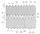
- the upper and lower rolls having a trapezoidal cross-sectional trapezoidal protrusion 3A / 3B having a spacing (pitch) P of 7 mm and a recessed groove 4A / 4B between the protrusions 3A / 3B having a depth D of 14 mm according to the above-described embodiment.
- the interval (pitch) P is 10 mm
- the depth D of the concave grooves 34A and 34B between the ridges 33A and 33B is 2.5 mm.
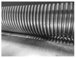
- the upper and lower rolls 2A and 2B of the embodiment had a substantially uniform particle size and an appropriate fineness.
- a glass cullet was obtained, and as shown in FIG. 15, the back sheet of the solar panel glass was not damaged, and as shown in FIG. 16, the crushed glass was not clogged in the recessed grooves 4A and 4B at all. It did not occur.
- the upper and lower rolls 32A and 32B of the comparative form as shown in FIG. 17, the back sheet of the solar panel glass was damaged and cracks were generated, which became crushed glass cullet as contamination (impurities). It was mixed.
- the crushed glass was clogged in the concave grooves 34A and 34B, and the protrusions 33A and 33B were also significantly worn.
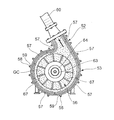
- the glass crusher 51 includes a crusher 52 having a drum portion 53 having a crushing rotor 56 for crushing a pre-crushed glass cullet, and a crusher.
- a substantially linear transport pipe 60 extending diagonally upward from 52 and guiding crushed glass in the drum portion 53, a container-shaped preduster 54 into which the upper end of the transport pipe 60 is inserted, and a preduster 54. It has a hopper 55 integrally provided at the lower part.
- 70 indicates a slot for the crushed glass cullet to be crushed.
- a plurality of arcuate wear-resistant steel plates are fixed as liners 57 on the inner peripheral surface of the drum portion 53 with bolts 58 and nuts 59.
- the inclination angle ⁇ of the transport pipe 60 with respect to the crusher 52 is about 60 °.
- the preduster 54 has a reflecting plate 61 that faces the upper end 60a of the transport pipe 60 and is inclined at a predetermined angle with respect to the axis of the transport pipe 60, and is a sandy glass discharged from the transport pipe 60.
- the powder collides with the reflecting plate 61 and is thrown into the preduster 54, and the sandy glass powder GS after colliding with the reflecting plate 61 is received by the hanging receiving plate 91 in the predaster 54 and falls smoothly, and the powder is smoothly dropped. It is thrown into the hopper 55. Further, the powdery glass powder GP filled in the predaster 54 flows into the chamber 95 connected to the upper part of the predaster 54, and then enters the collector 92 via the duct 94 and the butterfly damper 93.
- the collector 92 is provided with a dust collecting function including a bug filter and the like, and the powdery glass powder collected by the collector 92 is sand-like accumulated in the hopper 55. Like glass powder, it can be recycled as a material.
- the sandy glass powder GS falls into the hopper 55 by its own weight, and only the powdery glass GP having a very light specific gravity is sucked into the collector 92.
- 62 shows a window for visually observing the inside of the preduster 54.
- the crushing rotor 56 includes a circular substrate 66 having a bearing 64 of a rotary drive shaft 63 in the center, and a plurality of crushing plates 67 radially provided on one surface of the circular substrate 66.
- a ring-shaped plate 68 attached to the end of the entire crushed plate 67 is provided so as to orbit the end of each crushed plate 67.
- the rotary drive shaft 63 projects from the central portion of the drum portion 53, and the bearing 64 of the crushing rotor 56 is fitted to the rotary drive shaft 63 and fixed by the stop nut 71.
- the crushing rotor 56 is rotatably supported by such a structure.
- An inner lid 72 is attached to the drum portion 53 in which the crushing rotor 56 is built, and a door body 73 is attached to the outside of the inner lid 72 via a hinge 90, and the drum portion 53 is opened and closed by the door body 73. It is made free.
- the inner lid 72 has the same shape as the ring-shaped plate 68 of the crushing rotor 56.
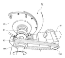
- the rotary drive shaft 63 of the crushing rotor 56 is rotated by the electric motor M via a pair of pulleys 74A and 74B, a belt B, and a bearing 81. It has a structure, and its rotation is such that the sandy glass powder crushed by the crushing rotor 56 is guided into the transport pipe 60.
- a sieving machine 75 is installed below the hopper 55.
- the glass cullet GC collides with the crushing plate 67 of the rotating crushing rotor 56 and is crushed, and after colliding with the crushing plate 67.
- the glass cullet GC is further crushed by colliding with a wear-resistant liner 57 attached to the inner peripheral surface of the drum portion 53 so as to surround the crushing rotor 56, and the drum portion 53 is further crushed in such a crushed state.
- the glass cullet GC which had sharp corners when it was thrown in from the slot 70 due to collision between the glass cullet GCs flying inside, was crushed and the sharp corners disappeared due to wear, and finally. It becomes a fine sandy glass powder GS with sharp edges.
- a swirling air vortex that winds up the glass cullet GC is generated in the drum portion 53 with the rotation of the crushing rotor 56, and the outer shape is crushed to about several millimeters by the above-mentioned crushing.
- the glass powder GS rises in the transport pipe 60 and is guided to the preduster 54 by the hoisting air vortex.
- the transport pipe 60 has a substantially direct shape, the sandy glass powder GC smoothly enters the preduster 54 without stagnation during transport and without any resistance.
- the sandy glass powder GS that has entered collides with the inclined reflective plate 61 arranged so as to face the upper end of the transport pipe 60, and further, the reflective plate 61 is subjected to the collision.
- the sandy glass powder GS after the collision is received by the hanging receiving plate 91 in the preduster 54 and falls downward, and finally the sandy glass powder GS falls on the hopper 55 below the predaster 54. Then, the sandy glass powder GS flows from the hopper 55 into the sieving machine 75.
- the glass cullet GC that has not been sufficiently crushed in the drum portion 53 does not rise due to the hoisting swirling air vortex in the drum portion 53 accompanying the rotation of the crushing rotor 56, but falls by its own weight and again the crushing rotor. It collides with the crushed plate 67 of 56, collides with the liner 57 due to the reaction thereof, and is further pulverized by the collision between the glass cullet GCs. Then, when the fine sandy glass powder GS whose outer shape is crushed to about several millimeters is obtained by repeating such crushing, the sandy glass powder GS becomes the drum portion 53 accompanying the rotation of the crushing rotor 56. It rises by the winding swirling air vortex inside and is guided into the transport pipe 60.
Landscapes
- Engineering & Computer Science (AREA)
- Environmental & Geological Engineering (AREA)
- Food Science & Technology (AREA)
- Disintegrating Or Milling (AREA)
- Processing Of Solid Wastes (AREA)
Abstract
Le problème à résoudre par l'invention est de fabriquer un verre en feuilles pouvant présenter des diamètres du grain appropriés en état séché, et d'uniformiser les diamètres du grain à l'aide d'un procédé simple. La solution de l'invention comprend une étape de broyage de verre en feuilles (S0001) consistant à broyer un verre en feuilles afin de produire du calcin de verre, et une étape de pulvérisation de calcin de verre (S0002) consistant à pulvériser le calcin de verre, produit dans l'étape précédente, pour obtenir une poudre de verre du type sable, et éventuellement une étape de tamisage de poudre de verre du type sable (S0003) consistant à tamiser la poudre de verre du type sable produite dans l'étape de pulvérisation de calcin de verre. En outre, éventuellement, la solution de l'invention comprend également une étape de pulvérisation de poudre de verre (S0004) consistant à renvoyer une partie de la poudre de verre du type sable présentant une dimension de grain supérieure à une dimension de grain prédéfinie, dans l'étape de tamisage de poudre de verre du type sable (S0003), vers l'étape de pulvérisation de calcin de verre (S0002), afin de pulvériser à nouveau ladite partie, et une étape de piégeage de poussières de poudre de verre (S0005) (S0006) consistant à piéger les poussières de poudre de verre formées dans l'étape de broyage de verre en feuilles (S0001) et/ou dans l'étape de pulvérisation de calcin de verre (S0002).
Priority Applications (2)
| Application Number | Priority Date | Filing Date | Title |
|---|---|---|---|
| PCT/JP2020/014135 WO2021192254A1 (fr) | 2020-03-27 | 2020-03-27 | Procédé et système de recyclage de verre en feuilles |
| JP2020545810A JP6857889B1 (ja) | 2020-03-27 | 2020-03-27 | 板ガラスのリサイクル方法およびリサイクルシステム |
Applications Claiming Priority (1)
| Application Number | Priority Date | Filing Date | Title |
|---|---|---|---|
| PCT/JP2020/014135 WO2021192254A1 (fr) | 2020-03-27 | 2020-03-27 | Procédé et système de recyclage de verre en feuilles |
Publications (1)
| Publication Number | Publication Date |
|---|---|
| WO2021192254A1 true WO2021192254A1 (fr) | 2021-09-30 |
Family
ID=75378010
Family Applications (1)
| Application Number | Title | Priority Date | Filing Date |
|---|---|---|---|
| PCT/JP2020/014135 Ceased WO2021192254A1 (fr) | 2020-03-27 | 2020-03-27 | Procédé et système de recyclage de verre en feuilles |
Country Status (2)
| Country | Link |
|---|---|
| JP (1) | JP6857889B1 (fr) |
| WO (1) | WO2021192254A1 (fr) |
Cited By (1)
| Publication number | Priority date | Publication date | Assignee | Title |
|---|---|---|---|---|
| EP4169619A1 (fr) * | 2021-10-21 | 2023-04-26 | Erutec GmbH | Procédé et dispositif de production de modules photovoltaïques |
Families Citing this family (1)
| Publication number | Priority date | Publication date | Assignee | Title |
|---|---|---|---|---|
| JP7683948B2 (ja) * | 2023-06-26 | 2025-05-27 | マスダ商事株式会社 | 廃ガラスの再生処理方法及び再生処理システム |
Citations (9)
| Publication number | Priority date | Publication date | Assignee | Title |
|---|---|---|---|---|
| US5950936A (en) * | 1998-01-21 | 1999-09-14 | Bergart; David | Process and system for recycling glass |
| JP2002186952A (ja) * | 2000-12-20 | 2002-07-02 | Central Glass Co Ltd | 合わせガラスをガラス片と中間膜片とに分離して回収する装置 |
| JP2004181321A (ja) * | 2002-12-02 | 2004-07-02 | Yasushi Shimomura | 合わせガラスやラミネートガラスをガラスとフイルムとに分離して回収する方法及び装置 |
| JP2004216234A (ja) * | 2003-01-10 | 2004-08-05 | Nippon Sheet Glass Co Ltd | 廃ガラス材のリサイクル方法、及び該方法によって製造されたガラスカレット |
| JP2004269278A (ja) * | 2003-03-05 | 2004-09-30 | Honda Motor Co Ltd | 合せガラスの分離方法及び該方法のための分離装置 |
| JP2011183243A (ja) * | 2010-03-04 | 2011-09-22 | Panasonic Corp | ガラスリサイクル方法及びシステム |
| JP2013223841A (ja) * | 2012-04-23 | 2013-10-31 | Sharp Corp | フラットパネルの再資源化方法 |
| JP2015205249A (ja) * | 2014-04-22 | 2015-11-19 | 株式会社環境保全サービス | ガラス分離装置 |
| JP2016203128A (ja) * | 2015-04-28 | 2016-12-08 | 株式会社環境保全サービス | ガラス分離装置 |
Family Cites Families (1)
| Publication number | Priority date | Publication date | Assignee | Title |
|---|---|---|---|---|
| US4795103A (en) * | 1987-05-21 | 1989-01-03 | Lech Stanley J | Pulverizing apparatus |
-
2020
- 2020-03-27 JP JP2020545810A patent/JP6857889B1/ja active Active
- 2020-03-27 WO PCT/JP2020/014135 patent/WO2021192254A1/fr not_active Ceased
Patent Citations (9)
| Publication number | Priority date | Publication date | Assignee | Title |
|---|---|---|---|---|
| US5950936A (en) * | 1998-01-21 | 1999-09-14 | Bergart; David | Process and system for recycling glass |
| JP2002186952A (ja) * | 2000-12-20 | 2002-07-02 | Central Glass Co Ltd | 合わせガラスをガラス片と中間膜片とに分離して回収する装置 |
| JP2004181321A (ja) * | 2002-12-02 | 2004-07-02 | Yasushi Shimomura | 合わせガラスやラミネートガラスをガラスとフイルムとに分離して回収する方法及び装置 |
| JP2004216234A (ja) * | 2003-01-10 | 2004-08-05 | Nippon Sheet Glass Co Ltd | 廃ガラス材のリサイクル方法、及び該方法によって製造されたガラスカレット |
| JP2004269278A (ja) * | 2003-03-05 | 2004-09-30 | Honda Motor Co Ltd | 合せガラスの分離方法及び該方法のための分離装置 |
| JP2011183243A (ja) * | 2010-03-04 | 2011-09-22 | Panasonic Corp | ガラスリサイクル方法及びシステム |
| JP2013223841A (ja) * | 2012-04-23 | 2013-10-31 | Sharp Corp | フラットパネルの再資源化方法 |
| JP2015205249A (ja) * | 2014-04-22 | 2015-11-19 | 株式会社環境保全サービス | ガラス分離装置 |
| JP2016203128A (ja) * | 2015-04-28 | 2016-12-08 | 株式会社環境保全サービス | ガラス分離装置 |
Cited By (1)
| Publication number | Priority date | Publication date | Assignee | Title |
|---|---|---|---|---|
| EP4169619A1 (fr) * | 2021-10-21 | 2023-04-26 | Erutec GmbH | Procédé et dispositif de production de modules photovoltaïques |
Also Published As
| Publication number | Publication date |
|---|---|
| JP6857889B1 (ja) | 2021-04-14 |
| JPWO2021192254A1 (fr) | 2021-09-30 |
Similar Documents
| Publication | Publication Date | Title |
|---|---|---|
| CN207628480U (zh) | 一种建筑废料破碎筛选装置 | |
| KR101036948B1 (ko) | 폐플라스틱의 재활용 처리시스템 및 재활용 처리방법 | |
| JP6857889B1 (ja) | 板ガラスのリサイクル方法およびリサイクルシステム | |
| CN212069525U (zh) | 干法机制砂石筛分装置 | |
| CN210171550U (zh) | 一种工业固体废弃物碎料分选装置 | |
| CN109967494B (zh) | 一种处理建筑垃圾的工艺方法及系统装置 | |
| CN111604116A (zh) | 一种具备筛分功能的水泥熟料原料高效破碎机 | |
| JP2004243165A (ja) | 廃石膏ボード分別リサイクル方法とそのシステム | |
| CN212396861U (zh) | 一种基于预筛分技术的矿石破碎装置 | |
| CN218309981U (zh) | 废旧沥青循环破碎生产线 | |
| US5238195A (en) | Method for recycling wallboard | |
| CN113117797A (zh) | 一种土木工程建筑施工用废料处理装置 | |
| CN112371908A (zh) | 一种铸造废渣回收装置 | |
| CN220716059U (zh) | 一种建材废料收集装置 | |
| WO2000071257A1 (fr) | Reducteur et separateur pour preparer des plaques de platre et d'autres produits destines a etre recycles | |
| KR20030051484A (ko) | 공기분급기를 이용한 건식 모래 생산장치 및 그 방법 | |
| CN219965000U (zh) | 一种建筑废料回收分类再利用装置 | |
| CN113477332B (zh) | 一种建筑垃圾再生骨料方法 | |
| CN111468222B (zh) | 一种建筑垃圾用分类筛选装置 | |
| CN209753089U (zh) | 一种建筑垃圾回收处理装置 | |
| CN215353670U (zh) | 一种处理建筑垃圾用的分拣装置 | |
| CN114101273A (zh) | 一种建筑垃圾的回收加工处理方法 | |
| CN223875197U (zh) | 一种土建绿色建造用建筑垃圾粉碎装置 | |
| CN108816474A (zh) | 废弃混凝土再生骨料用细粉碎风力筛选机构 | |
| KR200236742Y1 (ko) | 건축폐기물의 재활용 처리장치 |
Legal Events
| Date | Code | Title | Description |
|---|---|---|---|
| ENP | Entry into the national phase |
Ref document number: 2020545810 Country of ref document: JP Kind code of ref document: A |
|
| 121 | Ep: the epo has been informed by wipo that ep was designated in this application |
Ref document number: 20927122 Country of ref document: EP Kind code of ref document: A1 |
|
| NENP | Non-entry into the national phase |
Ref country code: DE |
|
| 122 | Ep: pct application non-entry in european phase |
Ref document number: 20927122 Country of ref document: EP Kind code of ref document: A1 |