WO2021193187A1 - 作業車両 - Google Patents
作業車両 Download PDFInfo
- Publication number
- WO2021193187A1 WO2021193187A1 PCT/JP2021/010316 JP2021010316W WO2021193187A1 WO 2021193187 A1 WO2021193187 A1 WO 2021193187A1 JP 2021010316 W JP2021010316 W JP 2021010316W WO 2021193187 A1 WO2021193187 A1 WO 2021193187A1
- Authority
- WO
- WIPO (PCT)
- Prior art keywords
- control valve
- hydraulic oil
- electromagnetic control
- output
- rotation speed
- Prior art date
- Legal status (The legal status is an assumption and is not a legal conclusion. Google has not performed a legal analysis and makes no representation as to the accuracy of the status listed.)
- Ceased
Links
Images


Classifications
-
- E—FIXED CONSTRUCTIONS
- E02—HYDRAULIC ENGINEERING; FOUNDATIONS; SOIL SHIFTING
- E02F—DREDGING; SOIL-SHIFTING
- E02F3/00—Dredgers; Soil-shifting machines
- E02F3/04—Dredgers; Soil-shifting machines mechanically-driven
- E02F3/28—Dredgers; Soil-shifting machines mechanically-driven with digging tools mounted on a dipper- or bucket-arm, i.e. there is either one arm or a pair of arms, e.g. dippers, buckets
-
- E—FIXED CONSTRUCTIONS
- E02—HYDRAULIC ENGINEERING; FOUNDATIONS; SOIL SHIFTING
- E02F—DREDGING; SOIL-SHIFTING
- E02F9/00—Component parts of dredgers or soil-shifting machines, not restricted to one of the kinds covered by groups E02F3/00 - E02F7/00
- E02F9/20—Drives; Control devices
- E02F9/22—Hydraulic or pneumatic drives
- E02F9/2278—Hydraulic circuits
- E02F9/2282—Systems using center bypass type changeover valves
-
- E—FIXED CONSTRUCTIONS
- E02—HYDRAULIC ENGINEERING; FOUNDATIONS; SOIL SHIFTING
- E02F—DREDGING; SOIL-SHIFTING
- E02F9/00—Component parts of dredgers or soil-shifting machines, not restricted to one of the kinds covered by groups E02F3/00 - E02F7/00
- E02F9/20—Drives; Control devices
- E02F9/22—Hydraulic or pneumatic drives
- E02F9/2221—Control of flow rate; Load sensing arrangements
- E02F9/2225—Control of flow rate; Load sensing arrangements using pressure-compensating valves
- E02F9/2228—Control of flow rate; Load sensing arrangements using pressure-compensating valves including an electronic controller
-
- E—FIXED CONSTRUCTIONS
- E02—HYDRAULIC ENGINEERING; FOUNDATIONS; SOIL SHIFTING
- E02F—DREDGING; SOIL-SHIFTING
- E02F3/00—Dredgers; Soil-shifting machines
- E02F3/04—Dredgers; Soil-shifting machines mechanically-driven
- E02F3/28—Dredgers; Soil-shifting machines mechanically-driven with digging tools mounted on a dipper- or bucket-arm, i.e. there is either one arm or a pair of arms, e.g. dippers, buckets
- E02F3/36—Component parts
- E02F3/42—Drives for dippers, buckets, dipper-arms or bucket-arms
- E02F3/43—Control of dipper or bucket position; Control of sequence of drive operations
- E02F3/431—Control of dipper or bucket position; Control of sequence of drive operations for bucket-arms, front-end loaders, dumpers or the like
-
- E—FIXED CONSTRUCTIONS
- E02—HYDRAULIC ENGINEERING; FOUNDATIONS; SOIL SHIFTING
- E02F—DREDGING; SOIL-SHIFTING
- E02F9/00—Component parts of dredgers or soil-shifting machines, not restricted to one of the kinds covered by groups E02F3/00 - E02F7/00
- E02F9/20—Drives; Control devices
-
- E—FIXED CONSTRUCTIONS
- E02—HYDRAULIC ENGINEERING; FOUNDATIONS; SOIL SHIFTING
- E02F—DREDGING; SOIL-SHIFTING
- E02F9/00—Component parts of dredgers or soil-shifting machines, not restricted to one of the kinds covered by groups E02F3/00 - E02F7/00
- E02F9/20—Drives; Control devices
- E02F9/2025—Particular purposes of control systems not otherwise provided for
-
- E—FIXED CONSTRUCTIONS
- E02—HYDRAULIC ENGINEERING; FOUNDATIONS; SOIL SHIFTING
- E02F—DREDGING; SOIL-SHIFTING
- E02F9/00—Component parts of dredgers or soil-shifting machines, not restricted to one of the kinds covered by groups E02F3/00 - E02F7/00
- E02F9/20—Drives; Control devices
- E02F9/2058—Electric or electro-mechanical or mechanical control devices of vehicle sub-units
- E02F9/2083—Control of vehicle braking systems
-
- E—FIXED CONSTRUCTIONS
- E02—HYDRAULIC ENGINEERING; FOUNDATIONS; SOIL SHIFTING
- E02F—DREDGING; SOIL-SHIFTING
- E02F9/00—Component parts of dredgers or soil-shifting machines, not restricted to one of the kinds covered by groups E02F3/00 - E02F7/00
- E02F9/20—Drives; Control devices
- E02F9/22—Hydraulic or pneumatic drives
- E02F9/2246—Control of prime movers, e.g. depending on the hydraulic load of work tools
-
- E—FIXED CONSTRUCTIONS
- E02—HYDRAULIC ENGINEERING; FOUNDATIONS; SOIL SHIFTING
- E02F—DREDGING; SOIL-SHIFTING
- E02F9/00—Component parts of dredgers or soil-shifting machines, not restricted to one of the kinds covered by groups E02F3/00 - E02F7/00
- E02F9/20—Drives; Control devices
- E02F9/22—Hydraulic or pneumatic drives
- E02F9/225—Control of steering, e.g. for hydraulic motors driving the vehicle tracks
-
- E—FIXED CONSTRUCTIONS
- E02—HYDRAULIC ENGINEERING; FOUNDATIONS; SOIL SHIFTING
- E02F—DREDGING; SOIL-SHIFTING
- E02F9/00—Component parts of dredgers or soil-shifting machines, not restricted to one of the kinds covered by groups E02F3/00 - E02F7/00
- E02F9/20—Drives; Control devices
- E02F9/22—Hydraulic or pneumatic drives
- E02F9/2264—Arrangements or adaptations of elements for hydraulic drives
- E02F9/2267—Valves or distributors
-
- E—FIXED CONSTRUCTIONS
- E02—HYDRAULIC ENGINEERING; FOUNDATIONS; SOIL SHIFTING
- E02F—DREDGING; SOIL-SHIFTING
- E02F9/00—Component parts of dredgers or soil-shifting machines, not restricted to one of the kinds covered by groups E02F3/00 - E02F7/00
- E02F9/20—Drives; Control devices
- E02F9/22—Hydraulic or pneumatic drives
- E02F9/2278—Hydraulic circuits
- E02F9/2285—Pilot-operated systems
-
- E—FIXED CONSTRUCTIONS
- E02—HYDRAULIC ENGINEERING; FOUNDATIONS; SOIL SHIFTING
- E02F—DREDGING; SOIL-SHIFTING
- E02F9/00—Component parts of dredgers or soil-shifting machines, not restricted to one of the kinds covered by groups E02F3/00 - E02F7/00
- E02F9/26—Indicating devices
-
- F—MECHANICAL ENGINEERING; LIGHTING; HEATING; WEAPONS; BLASTING
- F15—FLUID-PRESSURE ACTUATORS; HYDRAULICS OR PNEUMATICS IN GENERAL
- F15B—SYSTEMS ACTING BY MEANS OF FLUIDS IN GENERAL; FLUID-PRESSURE ACTUATORS, e.g. SERVOMOTORS; DETAILS OF FLUID-PRESSURE SYSTEMS, NOT OTHERWISE PROVIDED FOR
- F15B11/00—Servomotor systems without provision for follow-up action; Circuits therefor
- F15B11/02—Systems essentially incorporating special features for controlling the speed or actuating force of an output member
- F15B11/028—Systems essentially incorporating special features for controlling the speed or actuating force of an output member for controlling the actuating force
-
- F—MECHANICAL ENGINEERING; LIGHTING; HEATING; WEAPONS; BLASTING
- F15—FLUID-PRESSURE ACTUATORS; HYDRAULICS OR PNEUMATICS IN GENERAL
- F15B—SYSTEMS ACTING BY MEANS OF FLUIDS IN GENERAL; FLUID-PRESSURE ACTUATORS, e.g. SERVOMOTORS; DETAILS OF FLUID-PRESSURE SYSTEMS, NOT OTHERWISE PROVIDED FOR
- F15B11/00—Servomotor systems without provision for follow-up action; Circuits therefor
- F15B11/08—Servomotor systems without provision for follow-up action; Circuits therefor with only one servomotor
-
- F—MECHANICAL ENGINEERING; LIGHTING; HEATING; WEAPONS; BLASTING
- F15—FLUID-PRESSURE ACTUATORS; HYDRAULICS OR PNEUMATICS IN GENERAL
- F15B—SYSTEMS ACTING BY MEANS OF FLUIDS IN GENERAL; FLUID-PRESSURE ACTUATORS, e.g. SERVOMOTORS; DETAILS OF FLUID-PRESSURE SYSTEMS, NOT OTHERWISE PROVIDED FOR
- F15B15/00—Fluid-actuated devices for displacing a member from one position to another; Gearing associated therewith
- F15B15/20—Other details, e.g. assembly with regulating devices
-
- F—MECHANICAL ENGINEERING; LIGHTING; HEATING; WEAPONS; BLASTING
- F15—FLUID-PRESSURE ACTUATORS; HYDRAULICS OR PNEUMATICS IN GENERAL
- F15B—SYSTEMS ACTING BY MEANS OF FLUIDS IN GENERAL; FLUID-PRESSURE ACTUATORS, e.g. SERVOMOTORS; DETAILS OF FLUID-PRESSURE SYSTEMS, NOT OTHERWISE PROVIDED FOR
- F15B21/00—Common features of fluid actuator systems; Fluid-pressure actuator systems or details thereof, not covered by any other group of this subclass
- F15B21/08—Servomotor systems incorporating electrically operated control means
- F15B21/087—Control strategy, e.g. with block diagram
-
- B—PERFORMING OPERATIONS; TRANSPORTING
- B60—VEHICLES IN GENERAL
- B60Y—INDEXING SCHEME RELATING TO ASPECTS CROSS-CUTTING VEHICLE TECHNOLOGY
- B60Y2200/00—Type of vehicle
- B60Y2200/40—Special vehicles
- B60Y2200/41—Construction vehicles, e.g. graders, excavators
- B60Y2200/415—Wheel loaders
-
- E—FIXED CONSTRUCTIONS
- E02—HYDRAULIC ENGINEERING; FOUNDATIONS; SOIL SHIFTING
- E02F—DREDGING; SOIL-SHIFTING
- E02F3/00—Dredgers; Soil-shifting machines
- E02F3/04—Dredgers; Soil-shifting machines mechanically-driven
- E02F3/28—Dredgers; Soil-shifting machines mechanically-driven with digging tools mounted on a dipper- or bucket-arm, i.e. there is either one arm or a pair of arms, e.g. dippers, buckets
- E02F3/283—Dredgers; Soil-shifting machines mechanically-driven with digging tools mounted on a dipper- or bucket-arm, i.e. there is either one arm or a pair of arms, e.g. dippers, buckets with a single arm pivoted directly on the chassis
-
- E—FIXED CONSTRUCTIONS
- E02—HYDRAULIC ENGINEERING; FOUNDATIONS; SOIL SHIFTING
- E02F—DREDGING; SOIL-SHIFTING
- E02F9/00—Component parts of dredgers or soil-shifting machines, not restricted to one of the kinds covered by groups E02F3/00 - E02F7/00
- E02F9/20—Drives; Control devices
- E02F9/2004—Control mechanisms, e.g. control levers
- E02F9/2012—Setting the functions of the control levers, e.g. changing assigned functions among operations levers, setting functions dependent on the operator or seat orientation
-
- F—MECHANICAL ENGINEERING; LIGHTING; HEATING; WEAPONS; BLASTING
- F15—FLUID-PRESSURE ACTUATORS; HYDRAULICS OR PNEUMATICS IN GENERAL
- F15B—SYSTEMS ACTING BY MEANS OF FLUIDS IN GENERAL; FLUID-PRESSURE ACTUATORS, e.g. SERVOMOTORS; DETAILS OF FLUID-PRESSURE SYSTEMS, NOT OTHERWISE PROVIDED FOR
- F15B11/00—Servomotor systems without provision for follow-up action; Circuits therefor
- F15B11/02—Systems essentially incorporating special features for controlling the speed or actuating force of an output member
- F15B11/04—Systems essentially incorporating special features for controlling the speed or actuating force of an output member for controlling the speed
- F15B11/042—Systems essentially incorporating special features for controlling the speed or actuating force of an output member for controlling the speed by means in the feed line, i.e. "meter in"
- F15B11/0423—Systems essentially incorporating special features for controlling the speed or actuating force of an output member for controlling the speed by means in the feed line, i.e. "meter in" by controlling pump output or bypass, other than to maintain constant speed
-
- F—MECHANICAL ENGINEERING; LIGHTING; HEATING; WEAPONS; BLASTING
- F15—FLUID-PRESSURE ACTUATORS; HYDRAULICS OR PNEUMATICS IN GENERAL
- F15B—SYSTEMS ACTING BY MEANS OF FLUIDS IN GENERAL; FLUID-PRESSURE ACTUATORS, e.g. SERVOMOTORS; DETAILS OF FLUID-PRESSURE SYSTEMS, NOT OTHERWISE PROVIDED FOR
- F15B13/00—Details of servomotor systems ; Valves for servomotor systems
- F15B13/02—Fluid distribution or supply devices characterised by their adaptation to the control of servomotors
- F15B13/04—Fluid distribution or supply devices characterised by their adaptation to the control of servomotors for use with a single servomotor
- F15B13/042—Fluid distribution or supply devices characterised by their adaptation to the control of servomotors for use with a single servomotor operated by fluid pressure
- F15B13/043—Fluid distribution or supply devices characterised by their adaptation to the control of servomotors for use with a single servomotor operated by fluid pressure with electrically-controlled pilot valves
- F15B13/0433—Fluid distribution or supply devices characterised by their adaptation to the control of servomotors for use with a single servomotor operated by fluid pressure with electrically-controlled pilot valves the pilot valves being pressure control valves
-
- F—MECHANICAL ENGINEERING; LIGHTING; HEATING; WEAPONS; BLASTING
- F15—FLUID-PRESSURE ACTUATORS; HYDRAULICS OR PNEUMATICS IN GENERAL
- F15B—SYSTEMS ACTING BY MEANS OF FLUIDS IN GENERAL; FLUID-PRESSURE ACTUATORS, e.g. SERVOMOTORS; DETAILS OF FLUID-PRESSURE SYSTEMS, NOT OTHERWISE PROVIDED FOR
- F15B2211/00—Circuits for servomotor systems
- F15B2211/20—Fluid pressure source, e.g. accumulator or variable axial piston pump
- F15B2211/205—Systems with pumps
- F15B2211/20507—Type of prime mover
- F15B2211/20523—Internal combustion engine
-
- F—MECHANICAL ENGINEERING; LIGHTING; HEATING; WEAPONS; BLASTING
- F15—FLUID-PRESSURE ACTUATORS; HYDRAULICS OR PNEUMATICS IN GENERAL
- F15B—SYSTEMS ACTING BY MEANS OF FLUIDS IN GENERAL; FLUID-PRESSURE ACTUATORS, e.g. SERVOMOTORS; DETAILS OF FLUID-PRESSURE SYSTEMS, NOT OTHERWISE PROVIDED FOR
- F15B2211/00—Circuits for servomotor systems
- F15B2211/20—Fluid pressure source, e.g. accumulator or variable axial piston pump
- F15B2211/205—Systems with pumps
- F15B2211/2053—Type of pump
- F15B2211/20538—Type of pump constant capacity
-
- F—MECHANICAL ENGINEERING; LIGHTING; HEATING; WEAPONS; BLASTING
- F15—FLUID-PRESSURE ACTUATORS; HYDRAULICS OR PNEUMATICS IN GENERAL
- F15B—SYSTEMS ACTING BY MEANS OF FLUIDS IN GENERAL; FLUID-PRESSURE ACTUATORS, e.g. SERVOMOTORS; DETAILS OF FLUID-PRESSURE SYSTEMS, NOT OTHERWISE PROVIDED FOR
- F15B2211/00—Circuits for servomotor systems
- F15B2211/30—Directional control
- F15B2211/31—Directional control characterised by the positions of the valve element
- F15B2211/3105—Neutral or centre positions
- F15B2211/3116—Neutral or centre positions the pump port being open in the centre position, e.g. so-called open centre
-
- F—MECHANICAL ENGINEERING; LIGHTING; HEATING; WEAPONS; BLASTING
- F15—FLUID-PRESSURE ACTUATORS; HYDRAULICS OR PNEUMATICS IN GENERAL
- F15B—SYSTEMS ACTING BY MEANS OF FLUIDS IN GENERAL; FLUID-PRESSURE ACTUATORS, e.g. SERVOMOTORS; DETAILS OF FLUID-PRESSURE SYSTEMS, NOT OTHERWISE PROVIDED FOR
- F15B2211/00—Circuits for servomotor systems
- F15B2211/30—Directional control
- F15B2211/32—Directional control characterised by the type of actuation
- F15B2211/327—Directional control characterised by the type of actuation electrically or electronically
-
- F—MECHANICAL ENGINEERING; LIGHTING; HEATING; WEAPONS; BLASTING
- F15—FLUID-PRESSURE ACTUATORS; HYDRAULICS OR PNEUMATICS IN GENERAL
- F15B—SYSTEMS ACTING BY MEANS OF FLUIDS IN GENERAL; FLUID-PRESSURE ACTUATORS, e.g. SERVOMOTORS; DETAILS OF FLUID-PRESSURE SYSTEMS, NOT OTHERWISE PROVIDED FOR
- F15B2211/00—Circuits for servomotor systems
- F15B2211/30—Directional control
- F15B2211/32—Directional control characterised by the type of actuation
- F15B2211/329—Directional control characterised by the type of actuation actuated by fluid pressure
-
- F—MECHANICAL ENGINEERING; LIGHTING; HEATING; WEAPONS; BLASTING
- F15—FLUID-PRESSURE ACTUATORS; HYDRAULICS OR PNEUMATICS IN GENERAL
- F15B—SYSTEMS ACTING BY MEANS OF FLUIDS IN GENERAL; FLUID-PRESSURE ACTUATORS, e.g. SERVOMOTORS; DETAILS OF FLUID-PRESSURE SYSTEMS, NOT OTHERWISE PROVIDED FOR
- F15B2211/00—Circuits for servomotor systems
- F15B2211/50—Pressure control
- F15B2211/505—Pressure control characterised by the type of pressure control means
- F15B2211/50554—Pressure control characterised by the type of pressure control means the pressure control means controlling a pressure downstream of the pressure control means, e.g. pressure reducing valve
-
- F—MECHANICAL ENGINEERING; LIGHTING; HEATING; WEAPONS; BLASTING
- F15—FLUID-PRESSURE ACTUATORS; HYDRAULICS OR PNEUMATICS IN GENERAL
- F15B—SYSTEMS ACTING BY MEANS OF FLUIDS IN GENERAL; FLUID-PRESSURE ACTUATORS, e.g. SERVOMOTORS; DETAILS OF FLUID-PRESSURE SYSTEMS, NOT OTHERWISE PROVIDED FOR
- F15B2211/00—Circuits for servomotor systems
- F15B2211/50—Pressure control
- F15B2211/575—Pilot pressure control
-
- F—MECHANICAL ENGINEERING; LIGHTING; HEATING; WEAPONS; BLASTING
- F15—FLUID-PRESSURE ACTUATORS; HYDRAULICS OR PNEUMATICS IN GENERAL
- F15B—SYSTEMS ACTING BY MEANS OF FLUIDS IN GENERAL; FLUID-PRESSURE ACTUATORS, e.g. SERVOMOTORS; DETAILS OF FLUID-PRESSURE SYSTEMS, NOT OTHERWISE PROVIDED FOR
- F15B2211/00—Circuits for servomotor systems
- F15B2211/60—Circuit components or control therefor
- F15B2211/63—Electronic controllers
- F15B2211/6303—Electronic controllers using input signals
- F15B2211/6306—Electronic controllers using input signals representing a pressure
- F15B2211/6309—Electronic controllers using input signals representing a pressure the pressure being a pressure source supply pressure
-
- F—MECHANICAL ENGINEERING; LIGHTING; HEATING; WEAPONS; BLASTING
- F15—FLUID-PRESSURE ACTUATORS; HYDRAULICS OR PNEUMATICS IN GENERAL
- F15B—SYSTEMS ACTING BY MEANS OF FLUIDS IN GENERAL; FLUID-PRESSURE ACTUATORS, e.g. SERVOMOTORS; DETAILS OF FLUID-PRESSURE SYSTEMS, NOT OTHERWISE PROVIDED FOR
- F15B2211/00—Circuits for servomotor systems
- F15B2211/60—Circuit components or control therefor
- F15B2211/63—Electronic controllers
- F15B2211/6303—Electronic controllers using input signals
- F15B2211/633—Electronic controllers using input signals representing a state of the prime mover, e.g. torque or rotational speed
-
- F—MECHANICAL ENGINEERING; LIGHTING; HEATING; WEAPONS; BLASTING
- F15—FLUID-PRESSURE ACTUATORS; HYDRAULICS OR PNEUMATICS IN GENERAL
- F15B—SYSTEMS ACTING BY MEANS OF FLUIDS IN GENERAL; FLUID-PRESSURE ACTUATORS, e.g. SERVOMOTORS; DETAILS OF FLUID-PRESSURE SYSTEMS, NOT OTHERWISE PROVIDED FOR
- F15B2211/00—Circuits for servomotor systems
- F15B2211/60—Circuit components or control therefor
- F15B2211/63—Electronic controllers
- F15B2211/6303—Electronic controllers using input signals
- F15B2211/6346—Electronic controllers using input signals representing a state of input means, e.g. joystick position
-
- F—MECHANICAL ENGINEERING; LIGHTING; HEATING; WEAPONS; BLASTING
- F15—FLUID-PRESSURE ACTUATORS; HYDRAULICS OR PNEUMATICS IN GENERAL
- F15B—SYSTEMS ACTING BY MEANS OF FLUIDS IN GENERAL; FLUID-PRESSURE ACTUATORS, e.g. SERVOMOTORS; DETAILS OF FLUID-PRESSURE SYSTEMS, NOT OTHERWISE PROVIDED FOR
- F15B2211/00—Circuits for servomotor systems
- F15B2211/60—Circuit components or control therefor
- F15B2211/665—Methods of control using electronic components
-
- F—MECHANICAL ENGINEERING; LIGHTING; HEATING; WEAPONS; BLASTING
- F15—FLUID-PRESSURE ACTUATORS; HYDRAULICS OR PNEUMATICS IN GENERAL
- F15B—SYSTEMS ACTING BY MEANS OF FLUIDS IN GENERAL; FLUID-PRESSURE ACTUATORS, e.g. SERVOMOTORS; DETAILS OF FLUID-PRESSURE SYSTEMS, NOT OTHERWISE PROVIDED FOR
- F15B2211/00—Circuits for servomotor systems
- F15B2211/60—Circuit components or control therefor
- F15B2211/67—Methods for controlling pilot pressure
Definitions
- the present invention relates to a work vehicle in which a cargo handling work device is operated by an electric operation lever.
- a hydraulic pump for discharging hydraulic oil for driving the work device and various other accessories are driven by an engine. Therefore, when the work device is operated in a relief operation while the engine is idle, the sum of the drive torque on the hydraulic pump side and the drive torque on the auxiliary machinery side may exceed the output torque of the engine. If a load that exceeds the output torque of the engine is applied to the engine, the engine will stall.
- the wheel loader described in Patent Document 1 is discharged from a hydraulic pump for a working device by using a load switching valve used for clearing the clogging of the filter of the exhaust gas purification device and regenerating the filter.
- the hydraulic oil is unloaded into the tank, but for example, in the case of a work vehicle that employs a selective catalytic reduction system (SCR system) as an exhaust gas treatment system, a filter is not required, so a load switching valve Is not equipped.
- SCR system selective catalytic reduction system
- a dedicated circuit for unloading the hydraulic oil discharged from the hydraulic pump for the work device to the tank is separately required. Therefore, the number of parts mounted on the vehicle body increases, the vehicle body becomes large, and the work space is restricted accordingly.
- an object of the present invention is to suppress the occurrence of engine stall in a work vehicle in which a cargo handling work device is operated by an electric operation lever, regardless of the type of system mounted on the vehicle body.
- the present invention includes a working device attached to a vehicle body, a hydraulic actuator for driving the working device, and a hydraulic pump driven by an engine to supply hydraulic oil to the hydraulic actuator.
- a directional control valve that controls the flow of hydraulic oil discharged from the hydraulic pump and supplied to the hydraulic actuator, a hydraulic oil tank that stores the hydraulic oil, and a control pressure for switching and controlling the directional control valve are controlled.
- the work vehicle has a pressure sensor for detecting the discharge pressure of the hydraulic pump and a rotation speed sensor for detecting the rotation speed of the engine, and the direction control valve discharges from the hydraulic pump.
- the controller includes a neutral position for returning the hydraulic oil to the hydraulic oil tank, and the controller detects that the discharge pressure detected by the pressure sensor is equal to or higher than the relief pressure in the drive circuit of the hydraulic actuator and is detected by the rotation speed sensor.
- the output of the control signal to the electromagnetic control valve is limited so that the directional control valve switches to the neutral position. It is characterized by that.
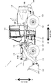
- FIG. 1 is an external side view showing a configuration example of the wheel loader 1 according to the embodiment of the present invention.
- the wheel loader 1 is an articulated work vehicle that is steered by bending the vehicle body near the center.
- the front frame 110 which is the front part of the vehicle body
- the rear frame 120 which is the rear part of the vehicle body
- the rod of the steering cylinder 116 expands and contracts.
- the front frame 110 bends in the left-right direction with respect to the rear frame 120.
- the left hand side in the forward direction is referred to as "left direction”
- right hand side is referred to as "right direction”.
- the front frame 110 is provided with a pair of left and right front wheels 113
- the rear frame 120 is provided with a pair of left and right rear wheels 123
- the entire vehicle body is provided with four wheels 113 and 123.
- FIG. 1 shows only the left front wheel 113 and the rear wheel 123 among the four wheels 113 and 123.
- a hydraulically driven cargo handling work device 11 used for cargo handling work is attached to the front frame 110.
- the cargo handling work device 11 includes a lift arm 111 whose base end is rotatably attached to the front frame 110, two lift arm cylinders 117 that drive the lift arm 111 by expanding and contracting each rod 117A, and a lift arm.
- a bucket 112 rotatably attached to the tip of 111, a bucket cylinder 115 that drives the bucket 112 by expanding and contracting the rod 115A, and a bucket 112 and a bucket cylinder 115 rotatably connected to a lift arm 111. It has a bell crank 118 that constitutes a link mechanism with and.
- the lift arm 111 rotates upward with respect to the front frame 110 by supplying hydraulic oil discharged from the hydraulic pump 12 (see FIG. 2) to each of the two lift arm cylinders 117 and extending each rod 117A. As each rod 117A contracts, it rotates downward with respect to the front frame 110.
- the two lift arm cylinders 117 are arranged side by side in the left-right direction of the vehicle body, but in FIG. 1, only the lift arm cylinder 117 arranged on the left side is shown by a broken line.
- the bucket 112 is a work tool for scooping earth and sand and discharging the soil, and leveling the ground.
- the hydraulic oil discharged from the hydraulic pump 12 is supplied to the bucket cylinder 115, and the rod 115A extends.
- the rod 115A rotates (tilts) upward with respect to the lift arm 111, and the rod 115A contracts to rotate (dump) downward with respect to the lift arm 111.
- Both the bucket cylinder 115 and the two lift arm cylinders 117 correspond to the hydraulic actuators that drive the cargo handling work device 11.
- the driver's cab 121 on which the operator is boarded, the machine room 122 for accommodating various devices necessary for driving the wheel loader 1 such as the engine 190 (shown by the broken line in FIG. 1), and the vehicle body are tilted.
- a counter weight 124 is provided to maintain a balance with the cargo handling work device 11 so as not to prevent the load handling device 11.
- the driver's cab 121 is arranged at the front, the counterweight 124 is arranged at the rear, and the machine room 122 is arranged between the driver's cab 121 and the counterweight 124.
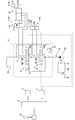
- FIG. 2 is a system configuration diagram illustrating the configuration of the drive system in the cargo handling work device 11.
- the drive system of the cargo handling work device 11 includes a bucket cylinder 115, two lift arm cylinders 117, a hydraulic pump 12 that supplies hydraulic oil to each cylinder 115, 117, and each cylinder 115, 117 discharged from the hydraulic pump 12.
- a directional control valve device 9 for controlling the flow (direction and flow rate) of the hydraulic oil supplied to the vehicle and a hydraulic oil tank 10 for storing the hydraulic oil are included.
- the hydraulic pump 12 is a fixed capacity type hydraulic pump driven by the engine 190.
- the discharge pressure P of the hydraulic pump 12 is detected by the pressure sensor 14 attached to the discharge port of the hydraulic pump 12.
- the rotation speed N of the engine 190 is detected by the rotation speed sensor 13 attached to the output shaft of the engine 190.
- the engine 190 also drives an auxiliary machine 15 other than the hydraulic pump 12.
- the directional control valve device 9 includes a first directional control valve 5 that switches and controls the flow of hydraulic oil discharged from the hydraulic pump 12 and supplied to the bucket cylinder 115, and two lift arm cylinders 117 discharged from the hydraulic pump 12.
- the second direction control valve 6 that switches and controls the flow of hydraulic oil supplied to each of the above, and the maximum pressure in the direction control valve device 9, that is, the relief pressure Pr in the drive circuits of the bucket cylinder 115 and the two lift arm cylinders 117. It has a specified main relief valve 16.
- the relief pressure Pr in the drive circuits of the bucket cylinder 115 and the two lift arm cylinders 117 can be arbitrarily set to a predetermined value, and in the following description, it is simply referred to as "main relief pressure Pr". do.
- the first direction control valve 5 and the second direction control valve 6 are open center type direction control valves, respectively, and are provided on the center bypass line 17 connecting the hydraulic pump 12 and the hydraulic oil tank 10.
- the second direction control valve 6 is connected to the first direction control valve 5 by a parallel line 18 branched from the upstream side of the first direction control valve 5 in the center bypass line 17 and connected to the upstream side of the second direction control valve 6. Connected in parallel.
- the first direction control valve 5 includes a first switching position 5L, a neutral position 5N, and a second switching position 5R.
- first switching position 5L the hydraulic oil discharged from the hydraulic pump 12 flows into the bottom chamber 115B of the bucket cylinder 115, and the hydraulic oil discharged from the rod chamber 115C is guided to the hydraulic oil tank 10.
- neutral position 5N the hydraulic oil discharged from the hydraulic pump 12 is returned to the hydraulic oil tank 10 as it is.
- the second switching position 5R the hydraulic oil discharged from the hydraulic pump 12 flows into the rod chamber 115C of the bucket cylinder 115, and the hydraulic oil discharged from the bottom chamber 115B is guided to the hydraulic oil tank 10.
- the first switching position 5L, the neutral position 5N, and the second switching position 5R are switched by moving the spool provided inside the first direction control valve 5.
- the spool is displaced in proportion to the control pressure supplied from the first electromagnetic control valve 3. Therefore, by controlling the control pressure supplied from the first electromagnetic control valve 3, the spool is displaced between the first switching position 5L and the neutral position 5N and between the second switching position 5R and the neutral position 5N. It is possible to control.
- the displacement amount of the spool is maximized in the state where the first direction control valve 5 is switched to the first switching position 5L and the state where the first switching position 5R is switched to the second switching position 5R (full stroke state). Further, in the state where the first direction control valve 5 is switched to the neutral position 5N, the displacement amount of the spool becomes 0 and the spool stops at the neutral position. At this time, the supply of the control pressure from the first electromagnetic control valve 3 is stopped.
- the bucket 112 is operated by an operation lever 19 as an electric operation device for operating the cargo handling work device 11.
- an operation lever 19 As an electric operation device for operating the cargo handling work device 11.
- the bucket operation signal related to the dump operation of the bucket 112 is output from the operation lever 19 to the controller 2.
- the controller 2 outputs a control signal according to the dump operation amount of the bucket 112 to the first electromagnetic control valve 3 based on the input bucket operation signal. Then, the first electromagnetic control valve 3 supplies the control pressure for switching and controlling the first direction control valve 5 to the second switching position 5R to the first direction control valve 5. As a result, the first direction control valve 5 is switched to the second switching position 5R, and the hydraulic oil is discharged from the bottom chamber 115R of the bucket cylinder 115, so that the rod 115A contracts and the bucket 112 dumps.
- the second direction control valve 6 includes a first switching position 6LF, a neutral position 6N, a second switching position 6R, and a third switching position 6LT.
- the first switching position 6LF causes the hydraulic oil discharged from the hydraulic pump 12 to flow into the rod chambers 117C of the two lift arm cylinders 117, respectively, and guides the hydraulic oil discharged from the bottom chamber 117B to the hydraulic oil tank 10.
- the second switching position 6R causes the hydraulic oil discharged from the hydraulic pump 12 to flow into the bottom chambers 117B of the two lift arm cylinders 117, respectively, and guides the hydraulic oil discharged from the rod chambers 117C to the hydraulic oil tank 10.
- the third switching position 6LT guides the hydraulic oil discharged from the bottom chamber 117B and the rod chamber 117C of each of the two lift arm cylinders 117 to the hydraulic oil tank 10.
- the first switching position 6LF, the neutral position 6N, the second switching position 6R, and the third switching position 6LT are switched by moving the spool provided inside the second direction control valve 6.
- the spool is displaced in proportion to the control pressure supplied from the second electromagnetic control valve 4. Therefore, by controlling the control pressure supplied from the second electromagnetic control valve 4, the displacement of the spool between the first switching position 6LF and the neutral position 6N and between the second switching position 6R and the neutral position 6N It is possible to control.
- the displacement amount of the spool is maximized in the state where the second direction control valve 6 is switched to the third switching position 6LT and the state where the second direction control valve 6 is switched to the second switching position 6R (full stroke state). Further, in the state where the second direction control valve 6 is switched to the neutral position 6N, the displacement amount of the spool becomes 0 and the spool stops at the neutral position. At this time, the supply of the control pressure from the second electromagnetic control valve 4 is stopped.
- the lift arm 111 is operated by the operating lever 19. That is, in the present embodiment, both the lift arm 111 and the bucket 112 are operated by the operating lever 19, but the present invention is not limited to this, and the lift arm 111 and the bucket 112 may be operated by different operating levers. For example, when the operation lever 19 is operated in the direction of raising the lift arm 111, the lift arm operation signal related to the raising operation of the lift arm 111 is output from the operation lever 19 to the controller 2.
- the controller 2 outputs a control signal corresponding to the lifting operation amount of the lift arm 111 to the second electromagnetic control valve 4 based on the input lift arm operation signal. Then, the second electromagnetic control valve 4 supplies the control pressure for switching and controlling the second direction control valve 6 to the first switching position 6LF to the second direction control valve 6. As a result, the second direction control valve 6 is switched to the first switching position 6LF, and the hydraulic oil flows into the bottom chamber 117B of each of the two lift arm cylinders 117, so that the rod 117A extends and the lift arm 111 rises. do.
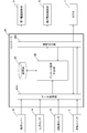
- FIG. 3 is a functional block diagram showing the functions of the controller 2.
- the controller 2 is configured by connecting the CPU, RAM, ROM, HDD, input I / F, and output I / F to each other via a bus. Then, various operating devices such as the operating lever 19 and various sensors such as the pressure sensor 14 and the rotation speed sensor 13 are connected to the input I / F, and the first electromagnetic control valve 3, the second electromagnetic control valve 4, and the monitor are connected. 7 and the like are connected to the output I / F.
- the monitor 7 is a display device provided in the driver's cab 121 that displays as an advice display that the controller 2 limits the output of the control signal to the first electromagnetic control valve 3 and the second electromagnetic control valve 4. be.
- the CPU reads the control program (software) stored in a recording medium such as a ROM, HDD, or optical disk, expands it on the RAM, and executes the expanded control program for control.
- the program and the hardware work together to realize the function of the controller 2.
- the controller 2 is described as a computer configured by a combination of software and hardware, but the present invention is not limited to this, and for example, as an example of the configuration of another computer, the wheel loader 1 side.
- An integrated circuit that realizes the function of the controller to be executed may be used.
- the controller 2 includes a data acquisition unit 21, an unload condition determination unit 22, a storage unit 23, and a signal output unit 24.
- the data acquisition unit 21 includes an operation signal output from the operation lever 19 according to the operation amount, a discharge pressure P of the hydraulic pump 12 detected by the pressure sensor 14 (hereinafter, simply referred to as “discharge pressure P”), and rotation. Data on the rotation speed N of the engine 190 detected by the number sensor 13 (hereinafter, simply referred to as “engine rotation speed N”) is acquired.
- the discharge pressure P acquired by the data acquisition unit 21 is equal to or higher than the main relief pressure Pr (P ⁇ Pr), and the engine speed N acquired by the data acquisition unit 21 is the engine 190. It is determined whether or not the unload condition is satisfied, which is lower than the low idle rotation speed NL, which is the rotation speed in the low idle state (N ⁇ NL).
- the main relief pressure Pr and the low idle rotation speed NL are stored in the storage unit 23, which is a memory.
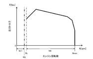
- the "low idle speed NL" is specifically an engine speed set in consideration of fuel efficiency, and is an engine speed that is also used during work. That is, the engine speed is set to the minimum necessary so that the engine 190 does not stall even when a workload is applied.
- FIGS. 7A and 7B are graphs showing the relationship between the engine speed and the output torque.
- the maximum value of the engine speed NL1 may be set to a speed NS slightly lower than the low idle speed NL.
- the unload condition determination unit 22 does not immediately determine that the unload condition is satisfied even if the engine speed N becomes lower than the low idle speed NL, and the unload condition is satisfied only when the engine speed NS is reached. Will be determined. In this way, the engine speed can be prevented from hunting by setting the speed NS having a margin from the low idle speed NL to the maximum value of the engine speed NL1.
- the engine speed of the low idle speed NL or higher corresponds to the engine speed NW applied during work, and is from the low idle speed NL to the maximum engine speed Nmax. It is set to the area in the range (NL ⁇ NW ⁇ Nmax).
- the maximum engine speed Nmax during work is set to the maximum engine speed with no load.
- the signal output unit 24 transmits the control signal based on the operation signal acquired by the data acquisition unit 21 to the first electromagnetic control valve 3 and Output to the second electromagnetic control valve 4, and when the unload condition determination unit 22 determines that the unload condition is satisfied, the output of the control signal to the first electromagnetic control valve 3 and the second electromagnetic control valve 4.
- the unload condition determination unit 22 is reacquired by the data acquisition unit 21. It is determined whether or not the engine speed N is equal to or higher than the low idle speed NL. Then, when the signal output unit 24 determines in the unload condition determination unit 22 that the engine speed N is equal to or higher than the low idle speed NL (N ⁇ NL), the first electromagnetic control valve 3 and the second electromagnetic control valve 3 and the second The restriction on the output of the control signal to the electromagnetic control valve 4 is released.
- the signal output unit 24 monitors the display signal for displaying the above-mentioned advice display when the output of the control signal to the first electromagnetic control valve 3 and the second electromagnetic control valve 4 is restricted. Output to 7. Then, when the signal output unit 24 releases the restriction on the output of the control signal to the first electromagnetic control valve 3 and the second electromagnetic control valve 4, the signal output unit 24 stops the output of the display signal to the monitor 7.
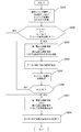
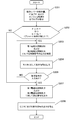
- FIG. 4 is a flowchart showing the flow of processing executed by the controller 2.
- the data acquisition unit 21 acquires the operation signal output from the operation lever 19 according to the operation amount, the discharge pressure P detected by the pressure sensor 14, and the engine speed N detected by the rotation speed sensor 13. (Step S201).
- the discharge pressure P acquired in step S201 is equal to or higher than the main relief pressure Pr, and the engine speed N acquired in step S201 is lower than the low idle speed NL. It is determined whether or not the engine speed is NL1, that is, whether or not the unload condition is satisfied (step S202).
- the signal output unit 24 limits the output of the control signal to the first electromagnetic control valve 3 and the second electromagnetic control valve 4. (Step S203).
- the first electromagnetic control valve 3 and the second electromagnetic control valve 4 limit the supply of the control pressure to the first direction control valve 5 and the second direction control valve 6, thereby limiting the supply of the control pressure to the first direction control valve 5 and the second electromagnetic control valve 5.
- the spools of the two-way control valve 6 are displaced toward the neutral positions 5N and 6N, respectively.
- the controller 2 limits the output of the control signal to the first electromagnetic control valve 3 and the second electromagnetic control valve 4, so that the hydraulic oil discharged from the hydraulic pump 12 is sent to the hydraulic oil tank 10.
- these first electromagnetic control valves 3 and second electromagnetic control valves 4 are devices that are always mounted on the vehicle body in which the cargo handling work device 11 is operated by the electric operation lever 19. It is possible to suppress the occurrence of stall of the engine 190 regardless of the type of system mounted on the vehicle body.
- the signal output unit 24 outputs a display signal for displaying advice to the monitor 7 while limiting the output of the control signal to the first electromagnetic control valve 3 and the second electromagnetic control valve 4. (Step S204).
- the controller 2 limits the output of the control signal to the first electromagnetic control valve 3 and the second electromagnetic control valve 4 by seeing the advice display displayed on the monitor 7. Can be done.
- the data acquisition unit 21 next acquires the engine speed N detected by the rotation speed sensor 13 again (step S205). Subsequently, the unload condition determination unit 22 determines whether or not the engine speed N reacquired in step S205 is the engine speed NW that is equal to or higher than the low idle speed NL (step S206).
- the restriction on the output of the control signal to the electromagnetic control valve 3 and the second electromagnetic control valve 4 is released, that is, the control signal corresponding to the operation amount of the operation lever 19 is output (step S207).
- the engine 190 since the engine 190 is in a state where it is difficult to stall, the hydraulic oil discharged from the hydraulic pump 12 is prevented from being unloaded into the hydraulic oil tank 10 more than necessary, and the cargo handling work device 11 is operated. I have secured it.
- the signal output unit 24 stops the output of the display signal to the monitor 7 (step S208), and the process in the controller 2 ends. Since the advice display displayed on the monitor 7 is hidden, the operator can easily recognize that the restriction on the output of the control signal to the first electromagnetic control valve 3 and the second electromagnetic control valve 4 has been released. Can be done.
- the specific display method of the advice display displayed on the monitor 7 is not particularly limited.
- step S203 is performed.
- the signal output unit 24 continuously limits the output of the control signal to the first electromagnetic control valve 3 and the second electromagnetic control valve 4.
- the output unit 24 outputs a control signal according to the operation amount of the operation lever 19 to the first electromagnetic control valve 3 and the second electromagnetic control valve 4.
- FIG. 5 is a functional block diagram showing the functions of the controller 2A according to the modified example of the present invention.
- FIG. 6 is a flowchart showing a flow of processing executed by the controller 2A according to the modified example of the present invention.
- the wheel loader 1 is a release switch 8 as a release device that outputs a release signal for releasing the restriction on the output of the control signal to the first electromagnetic control valve 3 and the second electromagnetic control valve 4 to the controller 2A.
- the release switch 8 is provided in the driver's cab 121 (see FIG. 1) and is manually operated by the operator.
- the release signal output from the release switch 8 is input to the data acquisition unit 21A of the controller 2A.
- the controller 2A sends a release signal to the data acquisition unit 21A. It is determined whether or not there is an input of (step S209).
- step S209 If a release signal is input in step S209 (step S209 / YES), the process proceeds to step S207, and the signal output unit 24A outputs a control signal to the first electromagnetic control valve 3 and the second electromagnetic control valve 4. Remove the restriction of. On the other hand, if there is no release signal input in step S209 (step S209 / NO), the process returns to step S203, and the signal output unit 24A continuously refers to the first electromagnetic control valve 3 and the second electromagnetic control valve 4. Limit the output of control signals.
- the restriction on the output of the control signal to the first electromagnetic control valve 3 and the second electromagnetic control valve 4 is released by the manual operation of the release switch 8 by the operator. Therefore, as in the embodiment, when the engine speed N becomes the low idle speed NL or more (N ⁇ NL) in the controller 2, the first electromagnetic control valve 3 and the second electromagnetic control valve 4 are automatically used.
- the cargo handling work device 11 generated by repeating the restriction and release of the control signal output to the first electromagnetic control valve 3 and the second electromagnetic control valve 4 as compared with the case of releasing the restriction on the output of the control signal to the first electromagnetic control valve 3 and the second electromagnetic control valve 4. The hunting operation can be suppressed.
- the controllers 2 and 2A both limit the output of the control signal to the first electromagnetic control valve 3 and the second electromagnetic control valve 4, but drive the lift arm 111 and the bucket 112.
- the output of the control signal to only one of the first electromagnetic control valve 3 and the second electromagnetic control valve 4 may be limited.
- the wheel loader has been described as an example of one aspect of the work vehicle, but the present invention is not limited to this, and any work vehicle provided with a work device operated by an electric operation device is not limited to this.
- it may be another work vehicle such as a hydraulic excavator.
Landscapes
- Engineering & Computer Science (AREA)
- General Engineering & Computer Science (AREA)
- Mining & Mineral Resources (AREA)
- Civil Engineering (AREA)
- Structural Engineering (AREA)
- Mechanical Engineering (AREA)
- Physics & Mathematics (AREA)
- Fluid Mechanics (AREA)
- Chemical & Material Sciences (AREA)
- Analytical Chemistry (AREA)
- Operation Control Of Excavators (AREA)
- Fluid-Pressure Circuits (AREA)
Abstract
Description
まず、ホイールローダ1の全体構成について、図1を参照して説明する。
次に、荷役作業装置11の駆動システムについて、図2を参照して説明する。
次に、コントローラ2の構成について、図3を参照して説明する。
次に、コントローラ2内で実行される処理の流れについて、図4を参照して説明する。
次に、本発明の変形例に係るホイールローダ1について、図5および図6を参照して説明する。なお、図5および図6において、実施形態に係るホイールローダ1について説明したものと共通する構成要素については、同一の符号を付してその説明を省略する。
2,2A:コントローラ
3:第1電磁制御弁
4:第2電磁制御弁
5:第1方向制御弁
5N,6N:中立位置
6:第2方向制御弁
7:モニタ(表示装置)
8:解除スイッチ(解除装置)
10:作動油タンク
12:油圧ポンプ
13:回転数センサ
14:圧力センサ
19:操作レバー(操作装置)
115:バケットシリンダ(油圧アクチュエータ)
117:リフトアームシリンダ(油圧アクチュエータ)
190:エンジン
NL:ローアイドル回転数
Pr:メインリリーフ圧
Claims (4)
- 車体に取り付けられた作業装置と、前記作業装置を駆動する油圧アクチュエータと、エンジンにより駆動されて前記油圧アクチュエータに作動油を供給する油圧ポンプと、前記油圧ポンプから吐出されて前記油圧アクチュエータに供給される作動油の流れを制御する方向制御弁と、作動油を貯留する作動油タンクと、前記方向制御弁を切り換え制御するための制御圧を前記方向制御弁に対して供給する電磁制御弁と、前記作業装置を操作するための電気式の操作装置と、前記操作装置の操作量に応じた制御信号を前記電磁制御弁に対して出力するコントローラと、を備えた作業車両において、
前記油圧ポンプの吐出圧を検出する圧力センサと、
前記エンジンの回転数を検出する回転数センサと、を有し、
前記方向制御弁は、前記油圧ポンプから吐出された作動油を前記作動油タンクへ戻す中立位置を含み、
前記コントローラは、
前記圧力センサで検出された吐出圧が前記油圧アクチュエータの駆動回路におけるリリーフ圧以上であって、前記回転数センサで検出された回転数が前記エンジンのローアイドル状態における回転数であるローアイドル回転数よりも低い場合、前記方向制御弁が前記中立位置に切り換わるように前記電磁制御弁に対する制御信号の出力を制限することを特徴とする作業車両。 - 請求項1記載の作業車両において、
前記コントローラは、
前記電磁制御弁に対する制御信号の出力を制限した後に、前記回転数センサで検出された回転数が前記ローアイドル回転数以上になると、前記電磁制御弁に対する制御信号の出力の制限を解除することを特徴とする作業車両。 - 請求項1記載の作業車両において、
前記電磁制御弁に対する制御信号の制限を解除する解除信号を前記コントローラに対して出力する解除装置をさらに有し、
前記コントローラは、
前記電磁制御弁に対する制御信号の出力を制限した後に、前記解除装置から出力された前記解除信号が入力されると、前記電磁制御弁に対する制御信号の出力の制限を解除することを特徴とする作業車両。 - 請求項1記載の作業車両において、
前記コントローラが前記電磁制御弁に対する制御信号の出力を制限している旨をアドバイス表示として表示する表示装置をさらに有し、
前記コントローラは、
前記電磁制御弁に対する制御信号の出力を制限している場合に、前記表示装置に対して前記アドバイス表示を表示するための表示信号を出力することを特徴とする作業車両。
Priority Applications (5)
| Application Number | Priority Date | Filing Date | Title |
|---|---|---|---|
| CN202180004816.XA CN114174600B (zh) | 2020-03-23 | 2021-03-15 | 作业车辆 |
| US17/638,296 US11753799B2 (en) | 2020-03-23 | 2021-03-15 | Work vehicle |
| EP21775190.8A EP4001517B1 (en) | 2020-03-23 | 2021-03-15 | Work vehicle |
| JP2022509946A JP7186330B2 (ja) | 2020-03-23 | 2021-03-15 | 作業車両 |
| KR1020227002525A KR102627826B1 (ko) | 2020-03-23 | 2021-03-15 | 작업 차량 |
Applications Claiming Priority (2)
| Application Number | Priority Date | Filing Date | Title |
|---|---|---|---|
| JP2020051505 | 2020-03-23 | ||
| JP2020-051505 | 2020-03-23 |
Publications (1)
| Publication Number | Publication Date |
|---|---|
| WO2021193187A1 true WO2021193187A1 (ja) | 2021-09-30 |
Family
ID=77892067
Family Applications (1)
| Application Number | Title | Priority Date | Filing Date |
|---|---|---|---|
| PCT/JP2021/010316 Ceased WO2021193187A1 (ja) | 2020-03-23 | 2021-03-15 | 作業車両 |
Country Status (6)
| Country | Link |
|---|---|
| US (1) | US11753799B2 (ja) |
| EP (1) | EP4001517B1 (ja) |
| JP (1) | JP7186330B2 (ja) |
| KR (1) | KR102627826B1 (ja) |
| CN (1) | CN114174600B (ja) |
| WO (1) | WO2021193187A1 (ja) |
Families Citing this family (3)
| Publication number | Priority date | Publication date | Assignee | Title |
|---|---|---|---|---|
| US20230356554A1 (en) * | 2020-09-17 | 2023-11-09 | Agco Corporation | Combine Stability Enhancer |
| US12071962B2 (en) * | 2022-11-28 | 2024-08-27 | Cnh Industrial America Llc | Reservoir with variable charge pressure |
| CN119711569B (zh) * | 2024-12-30 | 2025-10-31 | 雷沃重工集团有限公司 | 一种装载机的动臂举升高度限位系统、装载机及方法 |
Citations (4)
| Publication number | Priority date | Publication date | Assignee | Title |
|---|---|---|---|---|
| JP2000310202A (ja) * | 1999-04-26 | 2000-11-07 | Hitachi Constr Mach Co Ltd | 建設機械の油圧駆動装置 |
| JP2004150115A (ja) * | 2002-10-30 | 2004-05-27 | Komatsu Ltd | 油圧制御装置 |
| JP2015143545A (ja) * | 2014-01-31 | 2015-08-06 | 日立建機株式会社 | 油圧制御装置 |
| JP2019173395A (ja) * | 2018-03-28 | 2019-10-10 | 株式会社Kcm | ホイールローダ |
Family Cites Families (9)
| Publication number | Priority date | Publication date | Assignee | Title |
|---|---|---|---|---|
| JPS6175377U (ja) | 1984-10-23 | 1986-05-21 | ||
| JPH07158475A (ja) * | 1993-12-02 | 1995-06-20 | Yutani Heavy Ind Ltd | 建設機械のエンジン制御装置 |
| JP3868112B2 (ja) * | 1998-05-22 | 2007-01-17 | 株式会社小松製作所 | 油圧駆動機械の制御装置 |
| JP2001140678A (ja) * | 1999-11-18 | 2001-05-22 | Sumitomo Constr Mach Co Ltd | 建設機械搭載のエンジン制御装置 |
| JP5113129B2 (ja) * | 2008-09-01 | 2013-01-09 | 日産フォークリフト株式会社 | 産業車両の油圧回路装置 |
| JP5808686B2 (ja) * | 2012-02-03 | 2015-11-10 | 日立建機株式会社 | 作業車両のエンジン制御装置 |
| JP6259631B2 (ja) * | 2013-10-15 | 2018-01-10 | 株式会社タダノ | 作業機械の油圧ポンプの容量制御装置 |
| JP6134263B2 (ja) * | 2013-12-27 | 2017-05-24 | 株式会社Kcm | 油圧駆動システム |
| EP3553234A4 (en) * | 2016-12-06 | 2020-03-18 | Sumitomo (S.H.I.) Construction Machinery Co., Ltd. | CONSTRUCTION MACHINE |
-
2021
- 2021-03-15 KR KR1020227002525A patent/KR102627826B1/ko active Active
- 2021-03-15 JP JP2022509946A patent/JP7186330B2/ja active Active
- 2021-03-15 US US17/638,296 patent/US11753799B2/en active Active
- 2021-03-15 WO PCT/JP2021/010316 patent/WO2021193187A1/ja not_active Ceased
- 2021-03-15 EP EP21775190.8A patent/EP4001517B1/en active Active
- 2021-03-15 CN CN202180004816.XA patent/CN114174600B/zh active Active
Patent Citations (5)
| Publication number | Priority date | Publication date | Assignee | Title |
|---|---|---|---|---|
| JP2000310202A (ja) * | 1999-04-26 | 2000-11-07 | Hitachi Constr Mach Co Ltd | 建設機械の油圧駆動装置 |
| JP2004150115A (ja) * | 2002-10-30 | 2004-05-27 | Komatsu Ltd | 油圧制御装置 |
| JP2015143545A (ja) * | 2014-01-31 | 2015-08-06 | 日立建機株式会社 | 油圧制御装置 |
| JP6175377B2 (ja) | 2014-01-31 | 2017-08-02 | 株式会社Kcm | 油圧制御装置 |
| JP2019173395A (ja) * | 2018-03-28 | 2019-10-10 | 株式会社Kcm | ホイールローダ |
Non-Patent Citations (1)
| Title |
|---|
| See also references of EP4001517A4 |
Also Published As
| Publication number | Publication date |
|---|---|
| CN114174600B (zh) | 2023-05-12 |
| KR102627826B1 (ko) | 2024-01-23 |
| US11753799B2 (en) | 2023-09-12 |
| JP7186330B2 (ja) | 2022-12-08 |
| EP4001517B1 (en) | 2025-07-30 |
| JPWO2021193187A1 (ja) | 2021-09-30 |
| EP4001517A1 (en) | 2022-05-25 |
| KR20220024943A (ko) | 2022-03-03 |
| CN114174600A (zh) | 2022-03-11 |
| US20220356677A1 (en) | 2022-11-10 |
| EP4001517A4 (en) | 2023-09-13 |
Similar Documents
| Publication | Publication Date | Title |
|---|---|---|
| JP5048068B2 (ja) | 作業車両及び作業車両の作動油量制御方法 | |
| EP2269894B1 (en) | Steering controller and steering control method of working vehicle | |
| CN102037194B (zh) | 作业车辆、作业车辆的控制装置以及作业车辆的液压油量控制方法 | |
| JP7186330B2 (ja) | 作業車両 | |
| CN112424429B (zh) | 装卸作业车辆 | |
| US9702117B2 (en) | Work vehicle control method, work vehicle control device, and work vehicle | |
| EP3083369A1 (en) | A hydraulic load sensing system | |
| US9809948B2 (en) | Work vehicle control method, work vehicle control device, and work vehicle | |
| JP2011085159A (ja) | 作業機械の油圧駆動装置 | |
| US11280063B2 (en) | Work vehicle control system and work vehicle control method | |
| CN111771033A (zh) | 作业车辆 | |
| JP2011001744A (ja) | 建設機械の油圧制御装置 | |
| JP7038898B2 (ja) | 荷役作業車両 | |
| JP6928161B2 (ja) | 作業車両及び作業車両の制御方法 | |
| JP2011245909A (ja) | アウトリガ制御装置 | |
| WO2010052831A1 (ja) | 作業車両 | |
| CN113544389B (zh) | 作业机械 | |
| JP2021156121A (ja) | 作業車両 | |
| JP2025050352A (ja) | 電動式作業車両 | |
| WO2024257573A1 (ja) | ホイールローダ及びホイールローダを制御するための方法 | |
| JP2021156340A (ja) | 作業車両 |
Legal Events
| Date | Code | Title | Description |
|---|---|---|---|
| 121 | Ep: the epo has been informed by wipo that ep was designated in this application |
Ref document number: 21775190 Country of ref document: EP Kind code of ref document: A1 |
|
| ENP | Entry into the national phase |
Ref document number: 2022509946 Country of ref document: JP Kind code of ref document: A |
|
| ENP | Entry into the national phase |
Ref document number: 20227002525 Country of ref document: KR Kind code of ref document: A |
|
| ENP | Entry into the national phase |
Ref document number: 2021775190 Country of ref document: EP Effective date: 20220221 |
|
| NENP | Non-entry into the national phase |
Ref country code: DE |
|
| WWG | Wipo information: grant in national office |
Ref document number: 2021775190 Country of ref document: EP |