WO2010052831A1 - 作業車両 - Google Patents
作業車両 Download PDFInfo
- Publication number
- WO2010052831A1 WO2010052831A1 PCT/JP2009/005339 JP2009005339W WO2010052831A1 WO 2010052831 A1 WO2010052831 A1 WO 2010052831A1 JP 2009005339 W JP2009005339 W JP 2009005339W WO 2010052831 A1 WO2010052831 A1 WO 2010052831A1
- Authority
- WO
- WIPO (PCT)
- Prior art keywords
- work
- upper limit
- capacity
- pump
- boom
- Prior art date
- Legal status (The legal status is an assumption and is not a legal conclusion. Google has not performed a legal analysis and makes no representation as to the accuracy of the status listed.)
- Ceased
Links
Images




Classifications
-
- E—FIXED CONSTRUCTIONS
- E02—HYDRAULIC ENGINEERING; FOUNDATIONS; SOIL SHIFTING
- E02F—DREDGING; SOIL-SHIFTING
- E02F9/00—Component parts of dredgers or soil-shifting machines, not restricted to one of the kinds covered by groups E02F3/00 - E02F7/00
- E02F9/20—Drives; Control devices
- E02F9/22—Hydraulic or pneumatic drives
- E02F9/2221—Control of flow rate; Load sensing arrangements
- E02F9/2232—Control of flow rate; Load sensing arrangements using one or more variable displacement pumps
- E02F9/2235—Control of flow rate; Load sensing arrangements using one or more variable displacement pumps including an electronic controller
-
- E—FIXED CONSTRUCTIONS
- E02—HYDRAULIC ENGINEERING; FOUNDATIONS; SOIL SHIFTING
- E02F—DREDGING; SOIL-SHIFTING
- E02F9/00—Component parts of dredgers or soil-shifting machines, not restricted to one of the kinds covered by groups E02F3/00 - E02F7/00
- E02F9/20—Drives; Control devices
- E02F9/22—Hydraulic or pneumatic drives
- E02F9/2278—Hydraulic circuits
- E02F9/2296—Systems with a variable displacement pump
Definitions
- the present invention generally relates to a work vehicle represented by a construction vehicle such as a wheel loader or a power shovel, and in particular, a variable displacement fluid pump driven by an engine and a work driven by fluid from the fluid pump.
- a work vehicle equipped with a machine and a power train driven by an engine when traveling while performing a large energy consumption work such as lifting a load, fuel consumption is reduced by reducing wasted energy loss between the work machine and the power train.
- the present invention relates to a control technique for improving the quality.
- the work vehicle regardless of whether the high power mode or the low power mode is selected, the work vehicle is caused to travel at the same time while performing work with high energy consumption such as lifting a load on the work machine.
- the driver depresses the accelerator pedal fully in order to increase the work efficiency of the work implement, and at the same time depresses the brake pedal in order to moderately reduce the traveling speed of the vehicle. Accordingly, the output energy of the engine is wasted in the power train, resulting in poor fuel consumption.
- V-shape work is a typical work of the wheel loader.
- V-shape work involves excavating at a certain position, then raising the boom to lift the load (such as earth and sand) on the bucket and simultaneously moving the vehicle backward, then switching the transmission from reverse to forward, , Further advance the vehicle at the same time, approach the dump truck, dump the bucket and dump it on the dump truck, then go back and forth in the empty state and return to the excavation position again, That is the work.
- load lifting travel when performing the operation of moving the vehicle backward or forward while lifting the load
- the power train does not require so much torque, but the driver supplies excessive torque from the engine to the power train, which increases the engine speed. Because the vehicle speed that is exceeded by the brake is suppressed by the brake, the torque converter and the brake generate more heat than necessary and waste energy.
- an object of the present invention is to reduce wasteful energy loss in the power train and improve fuel efficiency when the work vehicle performs a high energy consumption operation such as lifting a load on the work machine while simultaneously running the vehicle. There is to improve.
- a work vehicle comprising an engine, a variable displacement fluid pump driven by the engine, a working machine driven by fluid from the fluid pump, and a power train driven by the engine.
- the work status detection means for determining whether the current work status of the work vehicle is “load lifting travel” in which the work machine lifts the load and simultaneously travels on the power train; and the work status detection
- the upper limit value of the capacity of the fluid pump is set to a predetermined first upper limit value when the currently detected work status is “lifting traveling”, and otherwise, the fluid pump Pump capacity upper limit control means for setting the upper limit value of the pump capacity to a predetermined second upper limit value smaller than the first upper limit value.
- Vehicle is provided.
- the upper limit of the capacity of the fluid pump for moving the work machine is increased when “load lifting” is performed, compared to other times.
- the engine matching rotational speed decreased, thereby causing the powertrain rotational speed and thus the traveling speed. Decreases. Accordingly, the amount of braking performed by the driver is reduced, wasteful energy consumption in the powertrain is reduced, and fuel efficiency is improved.
- the first upper limit value may be selected as the maximum capacity of the fluid pump.
- the second upper limit value may be selected as a capacity value that is necessary and sufficient to achieve a predetermined load lifting performance required for the work vehicle.
- the work status detection means determines whether or not the current work status is “during excavation” during excavation, and the current work status When the traveling mode of the work vehicle becomes reverse or neutral, or when the boom angle is higher than a predetermined value, the current work status transitions to “load lifting travel”. Then, when the angle of the bucket becomes lower than horizontal, the current work status is shifted to “soil removal” in which the soil is being removed. The current work status is changed to “empty driving” that is traveling without loading, and then the current work status is again “excavating”. Determines Luke may be configured. Thereby, when the wheel loader performs the V shape work, it is easy to determine whether or not the “load lifting traveling” is currently performed.
- the work vehicle when the work vehicle performs a large energy consumption operation such as lifting a load on the work machine while simultaneously running the vehicle, useless energy loss in the power train is reduced and fuel efficiency is improved.
- Explanatory drawing which shows the whole structure of the working vehicle of a present Example.
- Explanatory drawing which shows the function of a controller typically.
- Explanatory drawing which shows the work process of a wheel loader.
- FIG. 6 is a status transition diagram showing a work status determination operation.
- Explanatory drawing which arranged the judgment operation of work status in the form of a table.
- the flowchart which shows the flow of operation
- Explanatory drawing which shows the matching rotation speed of the engine in a wheel loader.
- FIG. 1 is a block diagram showing an outline of the overall configuration of the wheel loader.
- the wheel loader 1 includes a mechanical system 100 and a control circuit system (hereinafter referred to as a controller) 200.
- the mechanical system 100 will be described first, and then the controller 200 will be described.
- the mechanical system 100 includes, for example, an engine 101, a power train 103 that transmits power for driving the wheel loader 1 to the tire 3, a hydraulic system 104 that mainly drives the work machine 5 (FIG. 3), An output distributor (PTO: Power Take Off) 102 that distributes the output of the engine 101 to the power train 103 and the hydraulic system 104 is provided.
- An output distributor (PTO: Power Take Off) 102 that distributes the output of the engine 101 to the power train 103 and the hydraulic system 104 is provided.
- FIG. 3 is a side view of the wheel loader 1.
- the wheel loader 1 includes a vehicle body 2, a pair of tires 3 provided before and after the vehicle body 2, a machine room 4 provided at the rear of the vehicle body 2, a working machine 5 provided at the front of the vehicle body 2, and the vehicle body 2. And a driver's cab 6 provided at the center of the vehicle.
- the vehicle body 2 includes a rear vehicle body 21, a front vehicle body 22, and a connecting portion 23 that connects the rear vehicle body 21 and the front vehicle body 22.
- a pair of left and right steering cylinders 130 are provided between the rear vehicle body 21 and the front vehicle body 22.
- the machine room 4 houses the engine 101, each pump 120, and the like.
- the work machine 5 includes a boom 51 that is rotatably provided so as to extend forward from the front vehicle body 22, a bucket 52 that is rotatably provided at the tip of the boom 51, and the boom 51 is rotated in the vertical direction.
- the power train 103 includes, for example, a modulated clutch (hereinafter also referred to as a clutch) 110, a torque converter 111, a transmission 112, and an axle 113.
- a modulated clutch hereinafter also referred to as a clutch
- the clutch is abbreviated as “Mod / C”, the torque converter as “T / C”, and the transmission as “T / M”.
- the power (rotational torque) output from the engine 101 is transmitted to the tire 3 via the clutch 110, the torque converter 111, the transmission 112, and the axle 113.
- the transmission lever 114 is a device that is directly operated by the driver in order to switch the speed stage of the transmission 112.
- the transmission lever 114 includes, for example, an operation unit that is directly operated by the driver, and a shift signal generation unit that generates a shift signal for controlling the speed stage of the transmission 112 according to the position of the operation unit.
- the hydraulic system 104 includes a plurality of fluid pump (typically hydraulic pump) valves, actuators, operation inputs and auxiliary machines such as a work machine pump 120, a steering pump 122, a work machine valve 123, a steering valve 124, a bucket lever. 125, a boom lever 126, a steering lever 127, a boom cylinder 128, a bucket cylinder 129, a steering cylinder 130, an auxiliary pump 131, and an auxiliary 132.
- fluid pump typically hydraulic pump
- auxiliary machines such as a work machine pump 120, a steering pump 122, a work machine valve 123, a steering valve 124, a bucket lever. 125, a boom lever 126, a steering lever 127, a boom cylinder 128, a bucket cylinder 129, a steering cylinder 130, an auxiliary pump 131, and an auxiliary 132.
- the work machine pump 120 is a pump for supplying hydraulic oil to the boom cylinder 128 and the bucket cylinder 129.
- the steering pump 122 is a pump for supplying hydraulic oil to the steering cylinder 130.
- Each pump 120, 122, or at least the work machine pump 120 is configured as a variable displacement hydraulic pump, for example, a swash plate hydraulic pump, and the angle of each swash plate is controlled by a control signal from the controller 200. .
- a load sensing system is incorporated in the work machine pump 120.
- the swash plate angle of the work implement pump 120 is minimized to reduce the hydraulic loss.
- the present invention can also be applied when there is no load sensing system.
- the bucket lever 125 is a device that is directly operated by the driver to operate the bucket 52 by the driver.
- the boom lever 126 is a device that is directly operated by the driver to operate the boom 51 by the driver.
- the steering lever 127 is a device that is directly operated by the driver to operate the steering cylinder 130 by the driver.
- Each lever 125, 126, 127 includes, for example, an operation unit that is directly operated by a driver and a pilot pressure control valve that controls the pilot pressure in accordance with the operation amount of the operation unit.
- the main valve 123 supplies hydraulic oil discharged from the work implement pump 120 to the boom cylinder 128 and the bucket cylinder 129 in accordance with the pilot pressure input from the bucket lever 125 or the boom lever 126.
- the auxiliary machine 132 is a device such as a cooling fan driven by a hydraulic motor, for example.
- the auxiliary machine pump 131 is a pump for supplying hydraulic oil to the auxiliary machine 132.
- Various sensors 140 are provided at predetermined positions in the mechanical system 100.
- the various sensors 140 are generic names of sensors 141 to 146 described later with reference to FIG.
- Various states detected by the various sensors 140 are input to the controller 200 as electrical signals.
- the controller 200 is configured as an electronic circuit including, for example, a calculation unit 210, a memory 220, and an input / output interface unit 230. There are various functional components performed by the arithmetic unit 210, and among them, there are a work status detection unit 211 and a work machine pump capacity upper limit control unit 212 as functional components particularly relevant to the present invention.
- the work status detection unit 211 detects the status of the work currently being executed by the wheel loader 1 (that is, the type of work) as will be described later.
- the work machine pump capacity upper limit control means 212 detects the work status by detecting the upper limit value of the capacity of the work machine pump 120 (oil discharge amount per rotation of the work machine pump 120, cc / rev) (in other words, the swash plate angle). Control is performed according to the work status detected by the means 211. Details of operations of the work status detection unit 211 and the work machine pump capacity upper limit control unit 212 will be described later.
- the memory 220 is a storage medium that stores, for example, a program 221, various parameters 222, and a table 223.
- the calculation unit 210 reads the program 221 from the memory 220 and executes it to function as the work status detection unit 211 and the work machine pump capacity upper limit control unit 212 described above.
- Various parameters 222 include several threshold values, setting values, flag values, and the like used by the work status detection unit 211 and the work machine pump capacity upper limit control unit 212.
- the table 223 includes a data table used by the work status detection unit 211 and the work machine pump capacity upper limit control unit 212.
- the input / output interface unit 230 is a circuit for the controller 200 to transmit / receive electrical signals to / from the various sensors 140, the clutch 110, the transmission 112, and the pumps 120 to 122, 131.
- the calculation unit 210 receives signals from the various sensors 140 via the input / output interface unit 230.
- the arithmetic unit 210 outputs a control signal to the clutch 110 and the pumps 120 to 122 and 131 via the input / output interface unit 230. Note that the configuration of the controller 200 described above is illustrated with a simplified structure to the extent necessary for understanding and implementation of the present invention, and the present invention is not limited to the above-described configuration.
- FIG. 2 shows a functional configuration of the controller 200.
- the controller 200 is connected to a plurality of sensors 141 to 146 collectively referred to as various sensors 140 in FIG.
- FIG. 2 shows only a sensor that is closely related to the present invention.
- the term “sensor” is not limited to a sensor in a narrow sense that detects a value or state to be known, but a signal generator that outputs a value or state to be known, another detected signal or This means a sensor in a broad sense including an information processing device that determines a value or state desired to be known based on the state.
- the travel range sensor 141 detects whether the travel range set in the transmission 112 by the shift signal from the transmission lever 114 is forward (F), neutral (N), or reverse (R).
- the travel range sensor 141 may detect the speed stage of the transmission 112 instead of the travel range.
- the travel range sensor 141 may be a shift signal generation unit of the transmission lever 114.
- the boom bottom pressure sensor 142 detects the bottom pressure of the boom cylinder 128 that drives the boom 51 (FIG. 3) (hereinafter referred to as boom bottom pressure).
- the boom angle sensor 143 detects the angle of the boom 51 (FIG. 3).
- the bucket angle sensor 144 (or the bucket leveler proximity switch) determines whether the angle of the bucket 52 (FIG. 3), in particular, the angle of the bucket 52 is greater than or equal to the horizontal (or whether or not the bucket leveler is operating). To detect.
- the engine speed sensor 145 detects the speed of the engine 101.
- the various error sensors 146 detect or determine whether or not a failure or error has occurred in the mechanical system 100 or the controller 200.
- the work status detection means 211 in the controller 200 receives signals from the sensors 141 to 146 and detects the status of the work currently being performed (work type).
- the focus is focused on the V shape work of the wheel loader 1, and the V shape work is referred to as “during excavation”, “load lifting travel”, “soil removal”, and “empty travel”. Disassemble into 4 types of work status. Therefore, in this embodiment, the work status detection unit 211 determines whether the current work status is “excavating”, “load lifting traveling”, “discharging”, or “empty traveling”. To do.
- the work machine pump capacity upper limit control means 212 controls the upper limit value of the capacity of the work machine pump 120 (or the upper limit value of the swash plate angle) according to the current work status detected by the work status detection means 211. More specifically, the work machine pump capacity upper limit control means 212 sets the upper limit value (or the upper limit value of the swash plate angle) of the work machine pump 120 to a predetermined value when the work status “load lifting travel” is detected.
- the first upper limit value is set, and when any of the other work statuses “during excavation”, “discharging” and “empty travel” is detected, the upper limit value of the capacity of the work implement pump 120 is A predetermined second upper limit value smaller than the first upper limit value is set.
- the first upper limit value is equal to the maximum capacity (or maximum swash plate angle) determined from the mechanical structure of the work machine pump 120
- the second upper limit value is the maximum capacity (or maximum swash plate angle). It is a smaller value.
- the instantaneous capacity of the work machine pump 120 is also variably controlled by the other capacity control means 240.
- CLSS Click-Thruth
- the upper limit of the capacity range variable by the other capacity control means 240 is the upper limit value set by the work implement pump capacity upper limit control means 212, that is, the first upper limit value (the above-mentioned And is the second upper limit value (a value smaller than the maximum capacity) at the time of “drilling”, “soil removal”, and “empty traveling”.
- the load pressure of the work machine 5 is sufficiently high, so that the load pressure of the work machine 5 becomes excessive in other capacity control means 240 such as CLSS.
- the instantaneous capacity of the work implement pump 120 is maintained at the first upper limit value (maximum capacity) set by the work implement pump capacity upper limit control means 212, except in exceptional cases where the relief valve is activated. Become.
- the above-described control of the upper limit value of the capacity of the work implement pump 120 by the work implement pump capacity upper limit control means 212 means the following.
- the work implement pump 120 functions as a pump having an actual maximum capacity at the time of “load lifting travel”, but other “during excavation”, “soil removal” and “empty travel”
- it functions as a pump with a virtual maximum capacity that is smaller than its actual maximum capacity (ie, equal to the second upper limit) (in short, like a smaller pump).
- the actual maximum capacity is 160 cc / rev and the second upper limit value is 130 cc / rev
- the work equipment pump 120 may have its actual maximum capacity 160 cc / rev during the “loading traveling”.
- the rotational speed of the power train 103 that is, the traveling speed is reduced, and therefore the number or amount of braking by the driver is reduced, the wasteful consumption of energy in the power train 103 is reduced, and the fuel efficiency is improved.
- the maximum capacity (the first upper limit value) and the second upper limit value of the work implement pump 120 are appropriately set, which will be specifically described later.
- FIG. 4 is an explanatory diagram simply showing the flow of the V-shaping work of the wheel loader 1.
- the driver In the work status “excavating”, the driver lowers the bucket 52 to a position close to the ground, enters the bucket 11 into the object 11 such as earth and sand, and rotates the bucket 52 upward. Put the earth and sand into the bucket 52.
- the driver raises the boom 51 to lift the bucket 52 containing the load (sediment), and simultaneously reverses the wheel loader 1 as indicated by an arrow P2. Subsequently, the driver advances the wheel loader 1 to approach the dump truck 10 as indicated by an arrow P3 while continuing to raise the boom 51.
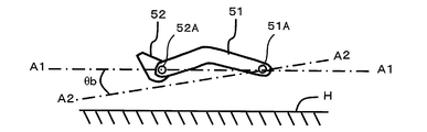
- FIG. 5 is an explanatory diagram of the angle of the boom 51.
- the detected value of the angle of the boom 51 is used to determine whether the current work status is “digging”, as will be described later.
- the angle formed by the line connecting the rotation fulcrum 51 ⁇ / b> A of the boom 51 and the rotation fulcrum 52 ⁇ / b> A of the bucket 52 with respect to the ground H is set to the rotation fulcrum 51 ⁇ / b> A of the boom 51.
- the angle aimed at the center is defined as the boom angle ⁇ b.
- the boom angle ⁇ b is 0 degree (the boom The angle ⁇ b is “horizontal”).
- the boom angle ⁇ b is Expressed as a negative value.
- the boom angle ⁇ b becomes a predetermined negative value (usually about ⁇ 30 degrees)
- the bucket 52 comes into contact with the ground H.
- a state in which the boom angle ⁇ b is larger (upward) than a negative predetermined value is defined as the boom angle being “above ground”.
- a negative predetermined value usually about ⁇ 30 degrees
- FIG. 6 shows a work status determination operation performed by the work status detection unit 211.
- FIG. 7 shows the determination operations organized in the form of a table.
- This determination operation is performed based on signals from the traveling range sensor 141, boom bottom pressure sensor 142, boom angle sensor 143, bucket angle sensor 144, engine speed sensor 145, and various error signal sensors 146 shown in FIG. Is called.
- the work status is determined as “unknown” S0.
- the work status transits to “empty travel” S1.
- the excavation flag is switched from OFF to ON when the operation status is “empty traveling” S1, the operation status transits to “under excavation” S2.
- the excavation flag is a flag indicating whether excavation is being performed, and will be described in detail later.
- the work status will be “Load lift travel” S3 or “Unload travel” S1 depending on the cause of the excavation flag switching. Transition to one of the following. That is, when the excavation flag is switched from ON to OFF due to a boom angle condition (described later) or a travel range condition (described later), the work status transits to “load lifting travel” S3. On the other hand, when the excavation flag is switched from ON to OFF under conditions related to the boom bottom pressure (described later), the work status transitions to “empty travel”.
- the work status transits to “under excavation” S2.
- the work status transits to “soil removal” S4.
- the work status transits to “empty travel” S1.
- the boom bottom pressure drop flag is a flag indicating whether or not the load is lifted, and will be described in detail later.
- the intermediate table pressure is a pressure registered as a function of the boom angle in the intermediate table as one of the various tables 223 shown in FIG. 1, and indicates whether or not the load is lifted. This is a threshold value for distinction based on the boom bottom pressure.
- the boom bottom pressure drop flag is turned off.
- the boom angle is less than the ground, the boom bottom pressure drop determination as described above is not performed.
- the maximum table pressure is a pressure registered as a function of the boom angle in the maximum table as one of the various tables 223 shown in FIG. 1, and indicates whether or not excavation is being performed. This is a threshold value for distinction based on the bottom pressure.
- the above-described operation for determining the work status is an example for explanation, and the present invention is not limited to this.
- the work status can also be determined in other ways. For example, the movement of a lever for operating the work machine may be detected, and the work status may be determined from the detection result.
- the maximum capacity (first upper limit value) of the work implement pump since it is only necessary to determine whether or not the maximum capacity (first upper limit value) of the work implement pump is required, it is possible to determine “load lifting travel” and one or more other work status types. May be.
- the types of work status may be “loading traveling”, “excavating”, “discharging, empty loading”, or even fewer.
- FIG. 8 shows an operation flow of the work machine pump capacity upper limit control means 212.
- the work machine pump capacity upper limit control means 212 determines whether or not the work status detection means 211 has detected the work status “loading traveling” in step S1. If the result is Yes, in step S2, the upper limit of the capacity of the work implement pump 120 is set to the above-described first upper limit value (the maximum capacity of the work implement pump 120). Otherwise, in step S3, The upper limit of the capacity of the work implement pump 120 is set to the above-described second upper limit value.
- the maximum capacity (first upper limit value) and the second upper limit value of the work machine pump 120 are selected in advance as follows. That is, the upper limit capacity of the work machine pump 120 necessary and sufficient to achieve a predetermined load lifting performance that is listed in the wheel loader 1 catalog (that is, that the wheel loader 1 must achieve) is the second capacity. It is selected as the upper limit. On the other hand, the maximum capacity (first upper limit value) of the work implement pump 120 is selected to be larger than the second upper limit value.
- the specifications of the parts other than the work machine pump 120 in the hydraulic system 104 for example, various pipes and valves) are selected as necessary and sufficient to achieve the rated boom rise time.
- the above-mentioned “predetermined load lifting performance” refers to the efficiency when lifting a load of a predetermined weight from a predetermined low position to a predetermined high position by a work machine when the vehicle is not traveling, for example, The time required for lifting or the speed of the lifting.
- the rated boom rising time is employed as an example of the “predetermined load lifting performance”.
- the rated boom rise time is a time measured under the following inspection conditions. That is, first, the bucket 52 is placed at the lowest position on the ground in the upward most inclined posture, and a predetermined regular load is loaded on the bucket 52.
- the boom 51 is lifted. Done.
- the time required for the bucket 52 to rise from the lowest position on the ground to the highest position (position at the stroke end of the boom cylinder 128) by this raising operation is measured. This measured time is the rated boom rise time.
- the upper limit capacity of the work machine pump 120 necessary and sufficient to achieve the rated boom rise time is selected as the second upper limit value.
- capacitance (1st upper limit value) of the working machine pump 120 is selected by the larger value.
- the maximum capacity of the work implement pump is set to be substantially equal to the capacity upper limit value sufficient to achieve the predetermined load lifting performance (for example, the rated boom rising time). . Therefore, the wheel loader 1 of the present embodiment is equipped with the work implement pump 120 having a larger maximum capacity compared to a wheel loader having a conventional equivalent load lifting performance (for example, rated boom rising time). It will be.
- FIG. 9 is a diagram for explaining the matching rotational speed of the engine 101 in the wheel loader 1 according to the present embodiment.
- reference numeral 400 indicates a maximum torque curve indicating the maximum torque that the engine 101 can output at each rotation speed.
- Both reference numerals 401 and 402 indicate the load torque imposed on the engine 101 when the wheel loader 1 lifts the load of the service load under the above-described inspection conditions, that is, the pump load torque from the hydraulic system 104 (work machine The curve (pump load torque curve) indicating the sum of the load torques of the pump 120, the steering pump 122, and the auxiliary pump 131 is indicated.
- the lower pump load torque curve 401 indicates the pump load torque when the capacity upper limit of the work implement pump 120 is set to the second upper limit value
- the higher pump load torque curve 402 indicates the work implement.
- capacitance (the said 1st upper limit value) is shown.
- Reference numerals 403 and 404 are both the load torque imposed on the engine 101 when the wheel loader 1 is traveling while lifting a load of a certain weight, that is, the hydraulic system.
- a curve (total load torque curve) indicating the sum of the pump load torque from 104 and the running load torque from the power train 103 is indicated.
- the lower total load torque curve 403 indicates the pump load torque when the capacity upper limit of the work machine pump 120 is set to the second upper limit value
- the higher total load torque curve 404 indicates the work machine The pump load torque when the capacity
- the work status is not “load lifting travel”, and the upper limit of the capacity of the work implement pump 120 is set to the second upper limit. Only the lower pump load torque curve 401 is valid. Therefore, the matching operating point of the engine 101 (the output torque of the engine 101 matches the total absorption torque of all loads including the hydraulic system 104 and the power train 103, and the engine operating point converges to this matching operating point. Is the operating point 401M. In this case, as described above, the time required for the bucket 52 to rise from the lowest position on the ground to the highest position is substantially the rated boom rise time.
- the matching operating point of the engine 101 is the operating point 402M.
- the matching operation points 401M and 402M are compared, since the gradient of the maximum torque curve 400 is steep, the matching rotation speed is not greatly different. Therefore, when the upper limit of the capacity of the work implement pump 120 increases, the boom ascent time is shortened almost according to the increase. This is because the oil amount is calculated by capacity (cc / rev) x matching rotation speed (rpm), and the oil amount necessary to raise the work equipment is unchanged, whereas the amount of oil supplied per unit time is This is because it increases.
- the upper limit of the capacity of the work machine pump 120 is set to the maximum capacity (the first upper limit value). Only curve 404 is valid. Therefore, the matching operating point of the engine 101 is the operating point 404M.
- the matching operating point of the engine 101 is the operating point 403M.
- the matching rotation speed is substantially reduced in accordance with the increment, and therefore the boom rising time is not changed much. This indicates that the amount of oil supplied per unit time does not change even if the capacity increases and the matching rotation speed decreases. Since it is important that the total amount of oil delivered from the pump does not change during the rated boom rise time, there is no problem even if the matching rotational speed is reduced.
- the power train 103 when the matching rotational speed of the engine 101 is considerably reduced, the rotational speed of the power train 103 and thus the traveling speed is considerably reduced. Therefore, the amount of braking for suppressing the traveling speed is reduced, wasteful energy consumption is reduced, and fuel consumption is improved.
- the wheel loader 1 according to the present embodiment is higher than the conventional wheel loader having substantially the same load lifting performance (rated boom rising time) as the boom lifting speed (the speed at which the load is lifted) at the time of “load lifting traveling”. ) Are the same (that is, what is normally expected from the performance described in the catalog, not excessively high), but the driving speed is lower, reducing the need for the driver to brake and fuel consumption Is good.
- FIG. 10 shows a conventional wheel loader (equipped with a work machine pump having a maximum capacity equal to the second upper limit value) having substantially the same load lifting performance (rated boom ascent time) as the wheel loader 1 according to the present embodiment.
- the changes in the boom angle [degree] and the engine speed [rpm] when V shape work is performed under the same conditions are shown.
- a solid line curve 410 indicates a change in the boom angle of the wheel loader 1 according to the present embodiment
- a dotted line curve 411 indicates that of a conventional wheel loader.
- a solid line curve 412 indicates a change in the engine speed of the wheel loader 1 according to this embodiment
- a dotted line curve 413 indicates that of a conventional wheel loader.
- the preferred embodiment of the present invention has been described above. However, this is an example for explaining the present invention, and the scope of the present invention is not limited to this embodiment.
- the present invention can be implemented in various modes different from the above-described embodiments without departing from the gist thereof.
- the operation and effect of the present invention have been described in relation to the maximum torque curve of the engine (see FIG. 9) for the sake of simplicity.
- the upper limit output torque curve that can be output by the engine at the maximum accelerator opening can be switched in multiple ways. Even when each upper limit output torque curve is selected, the control according to the present invention can be applied every time the upper limit output torque curve is selected. Can be obtained.
Landscapes
- Engineering & Computer Science (AREA)
- Mining & Mineral Resources (AREA)
- Civil Engineering (AREA)
- General Engineering & Computer Science (AREA)
- Structural Engineering (AREA)
- Physics & Mathematics (AREA)
- Fluid Mechanics (AREA)
- Operation Control Of Excavators (AREA)
Abstract
作業車両1は、必要とされる積荷持ち上げ性能を達成するのに必要十分な容量値よりも大きい最大容量をもつ容量可変型の作業機ポンプ120を搭載する。作業車両1が積荷持上げ走行を行っている時には、作業機ポンプ120の容量上限値はその最大容量に設定されるが、それ以外の時には、作業機ポンプ120の容量上限値はその最大容量より小さい上限値に設定される。この小さい上限値は、例えば、必要とされる積荷持ち上げ性能を達成するのに必要十分な容量値とすることができる。
Description
本発明は、一般には、ホイールローダやパワーショベルのような建設車両に代表される作業車両に関し、特に、エンジンにより駆動される可変容量型の流体ポンプと、流体ポンプからの流体で駆動される作業機と、エンジンにより駆動されるパワートレインとを備える作業車両において、積荷の持ち上げのようなエネルギー消費の大きい作業を行いつつ走行も行う時に、作業機とパワートレインの無駄なエネルギー損失を減らして燃費を改善するための制御技術に関する。
作業車両の燃費の改善のために、作業車両が掘削又は登坂走行のような負荷の大きい動作を行っているかどうかを判断して、自動的にエンジンのパワー出力能力(出力可能な最大の馬力)を高パワーモードと低パワーモードに切り替える制御が知られている(例えば特許文献1参照)。
従来の作業車両によれば、上記高パワーモードと低パワーモードのいずれが選択されているかにかかわりなく、積荷の持ち上げのような消費エネルギーの大きい作業を作業機で行いつつ同時に作業車両を走行させるときには、運転者は、作業機による作業能率を上げたいために、アクセルペダルをいっぱいに踏み込み、同時に、車両の走行速度を適度に抑制するために、ブレーキペダルを踏んでいることが多い。したがって、エンジンの出力エネルギーがパワートレインで無駄に消費されるから、燃費が悪い。
その典型例の一つに、ホイールローダの代表的な作業であるVシェープ作業における積荷持上げ走行がある。Vシェープ作業は、或る位置で掘削を行い、その後、ブームを上昇させてバケット上の積荷(土砂など)を持ち上げつつ、同時に車両を後進させ、その後、トランスミッションを後進から前進に切り替えて、ブームをさらに上げつつ同時に車両を前進させて、ダンプトラックにアプローチし、そして、バケットをダンプさせてダンプトラック上に排土し、その後、空荷状態で後進と前進を行って掘削位置へ再び戻る、という作業である。このようなVシェープ作業の前半で、積荷を持上げつつ車両を後進又は前進させる動作(以下、それぞれを「積荷持上げ走行」という)を行う際、運転者は、ブームレバーとステアリングを同時に操作しつつ、ブームの上昇スピードを速めるために、通常、アクセルペダルを大きく踏みエンジン回転速度を上げる(ブームやバケットなどの作業機は、通常、エンジンにより駆動される油圧ポンプからの圧油で駆動されるから、エンジン回転速度を上げれば、作業機の動作速度も上がる)。しかし、後進時は必要以上に遠くまで後退したくなく、続く前進時はダンプトラックに安全にアプローチしたいので、車速を低く抑える必要がある。そのため、運転者は、ブレーキを踏んで車速を抑制している。
すなわち、Vシェープ作業の積荷持上げ走行の時、パワートレインはそれほど大きいトルクを必要としないのに、運転者はエンジンから過大なトルクをパワートレインに供給するので、エンジンの回転速度が上昇し、それにより超過する車速をブレーキで抑制しているので、トルクコンバータやブレーキが必要以上に発熱して無駄にエネルギーを損失している。
他方、上記とは逆に、積荷持上げ走行時のエンジン回転速度をパワートレインに必要最小限の低さに抑えると、作業機の上昇スピードが不足し、それに伴い、後進と前進の走行距離をより長くする必要があるから、Vシェープ作業の能率が低下してしまう。
従って、本発明の目的は、作業車両が、積荷の持上げのようなエネルギー消費の大きい動作を作業機で行いつつ同時に車両を走行させる時、パワートレインでの無駄なエネルギー損失を低減して燃費を改善することにある。
本発明に従えば、エンジンと、前記エンジンにより駆動される可変容量型の流体ポンプと、前記流体ポンプからの流体で駆動される作業機と、前記エンジンにより駆動されるパワートレインとを備える作業車両において、前記作業車両の現在の作業ステータスが、前記作業機により積荷を持ち上げつつ同時に前記パワートレインで走行する「積荷持上げ走行」であるか否かを判断する作業ステータス検出手段と、前記作業ステータス検出手段に応答して、前記現在の検出された作業ステータスが「積荷持上げ走行」である時には、前記流体ポンプの容量の上限値を所定の第1上限値に設定し、そうでない時には、前記流体ポンプの容量の上限値を前記第1上限値より小さい所定の第2上限値に設定するポンプ容量上限制御手段とを備えた作業車両が、提供される。
この作業車両によると、「積荷持上げ走行」が行われる時には、それ以外の時に比べて、作業機を動かすための流体ポンプの容量上限が増加する。その結果、流体ポンプの容量上限が増加しなかったとした場合(つまり、従来の作業機械の場合)に比べて、エンジンのマッチング回転数が低下し、それにより、パワートレインの回転数、ひいては走行速度が低下する。よって、運転者がブレーキングをする量が減り、パワートレインでの無駄なエネルギー消費が減り、燃費が向上する。
前記第1上限値は、前記流体ポンプの最大容量に選定されてよい。また、前記第2上限値は、前記作業車両に必要とされる所定の積荷持ち上げ性能を達成するのに必要十分な容量値に選定されてよい。
ブームとバケットを作業機として有するホイールローダの場合、上記作業ステータス検出手段は、前記現在の作業ステータスが、掘削を行っている「掘削中」であるか否かを判断し、前記現在の作業ステータスを「掘削中」と判断した後に、前記作業車両の走行モードが後進又はニュートラルになるか、または前記ブームの角度が所定値より上方になると、前記現在の作業ステータスを「積荷持上げ走行」に遷移させ、その後に、前記バケットの角度が水平より低くなると、前記現在の作業ステータスを、排土を行っている「排土」に遷移させ、その後に、前記バケットの角度が水平以上になると、前記現在の作業ステータスを、積荷なしに走行している「空荷走行」に遷移させ、その後に再び、前記現在の作業ステータスが「掘削中」であるか否かを判断する、ように構成されてよい。これにより、ホイールローダがVシェープ作業を行うときに、「積荷持上げ走行」が現在行われているか否かを判断することが容易である。
本発明によれば、作業車両が、積荷持上げのようなエネルギー消費の大きい動作を作業機で行いつつ同時に車両を走行させる時、パワートレインでの無駄なエネルギー損失が低減されて燃費が改善する。
以下、図を参照しながら、本発明の実施例を、作業車両としてのホイールローダに適用した場合を例に挙げて説明する。但し、本実施例は、ホイールローダ以外の他の作業車両にも適用することができる。
図1は、ホイールローダの全体構成の概略を示すブロック図である。ホイールローダ1は、機械システム100と制御回路システム(以下、コントローラと呼ぶ)200とを備える。先に機械システム100について説明し、次にコントローラ200について説明する。
機械システム100は、例えば、エンジン101と、ホイールローダ1を走行させるための動力をタイヤ3に伝達するパワートレイン103と、主に作業機5(図3)を駆動するための油圧システム104と、エンジン101の出力をパワートレイン103及び油圧システム104に分配する出力分配器(PTO:Power Take Off)102とを備えている。
ここで、図3を参照する。図3は、ホイールローダ1の側面図である。ホイールローダ1は、車体2と、車体2の前後にそれぞれ一対ずつ設けられたタイヤ3と、車体2の後方に設けられる機械室4と、車体2の前方に設けられる作業機5と、車体2の中央部に設けられる運転室6とを備えている。
車体2は、後部車体21と、前部車体22と、後部車体21と前部車体22とを連結する連結部23とを備える。後部車体21と前部車体22との間には、左右一対のステアリングシリンダ130が設けられている。運転者が、運転室6内のステアリングレバー127(図1参照)を操作すると、この操作に応じて、一方のステアリングシリンダ130のシリンダロッドが伸長し、他方のステアリングシリンダ130のシリンダロッドが縮小する。これにより、ホイールローダ1は、進路を変えることができる。
機械室4は、エンジン101や各ポンプ120等を収容する。作業機5は、前部車体22から前方に延びるようにして回動可能に設けられるブーム51と、このブーム51の先端に回動可能に設けられるバケット52と、ブーム51を上下方向に回動させるためのブームシリンダ128と、バケット52を回動させるためのバケットシリンダ129とを備えている。
図1に戻る。パワートレイン103は、例えば、モジュレーテッドクラッチ(以下、クラッチとも呼ぶ)110と、トルクコンバータ111と、トランスミッション112と、アクスル113とを備えている。説明の便宜上、図中では、クラッチを「Mod/C」、トルクコンバータを「T/C」、トランスミッションを「T/M」とそれぞれ略記する。エンジン101から出力された動力(回転トルク)は、クラッチ110、トルクコンバータ111、トランスミッション112及びアクスル113を介して、タイヤ3に伝達される。
トランスミッションレバー114は、運転者がトランスミッション112の速度段を切り替えるために運転者により直接操作される装置である。トランスミッションレバー114は、例えば、運転者により直接操作される操作部と、操作部の位置に応じてトランスミッション112の速度段を制御するシフト信号を発生するシフト信号発生部とを備える。
油圧システム104は、複数の流体ポンプ(典型的には油圧ポンプ)バルブ、アクチュエータ、操作入力器及び補助機械、例えば、作業機ポンプ120、ステアリングポンプ122、作業機バルブ123、ステアリングバルブ124、バケットレバー125、ブームレバー126、ステアリングレバー127、ブームシリンダ128、バケットシリンダ129、ステアリングシリンダ130、補機用ポンプ131及び補機132を備える。
作業機ポンプ120は、ブームシリンダ128及びバケットシリンダ129に作動油を供給するためのポンプである。ステアリングポンプ122は、ステアリングシリンダ130に作動油を供給するためのポンプである。各ポンプ120,122、または少なくとも作業機ポンプ120は、容量可変型の油圧ポンプ、例えば、斜板型油圧ポンプとして構成され、それぞれの斜板の角度は、コントローラ200からの制御信号により制御される。
通常、作業機ポンプ120には、ロードセンシングシステムが組み込まれる。そのロードセンシングシステムは、操作入力がない場合には、作業機ポンプ120の斜板角度を最小にして、油圧ロスを減少させるようになっている。しかし、本発明は、ロードセンシングシステムが無い場合にも適用することができる。
上述したVシェープ作業中の積荷持上げ走行時のように、バケット52に荷を積んで持ち上げるような時には通常、オペレータはブームレバー126の操作入力を最大にし、よって、作業機ポンプ120の斜板角度は最大となり、ブームシリンダ128に作動油が供給される。
バケットレバー125は、運転者がバケット52を操作するために運転者により直接操作される装置である。ブームレバー126は、運転者がブーム51を操作するために運転者により直接操作される装置である。ステアリングレバー127は、運転者がステアリングシリンダ130を操作するために運転者により直接操作される装置である。各レバー125,126,127は、例えば、運転者により直接操作される操作部と、操作部の操作量に応じてパイロット圧を制御するパイロット圧制御弁とを備えて構成される。メインバルブ123は、バケットレバー125またはブームレバー126から入力されるパイロット圧に応じて、作業機ポンプ120から吐出される作動油を、ブームシリンダ128やバケットシリンダ129に供給する。
補機132は、例えば、油圧モータで駆動される冷却ファンのような装置である。補機用ポンプ131は、補機132に作動油を供給するためのポンプである。
機械システム100内の所定位置には、各種センサ140が設けられている。各種センサ140は、図2と共に後述するセンサ141~146の総称である。各種センサ140により検出された各種状態は、電気信号としてコントローラ200に入力される。
コントローラ200は、例えば、演算部210と、メモリ220と、入出力インターフェース部230とを備えた電子回路として構成される。演算部210が行う機能コンポーネントには、様々なものがあるが、そのうち、特に本発明に関係の深い機能コンポーネントとして、作業ステータス検出手段211と、作業機ポンプ容量上限制御手段212とがある。
作業ステータス検出手段211は、後述するようにホイールローダ1が現在実行している作業のステータス(すなわち作業の種類)を検出する。作業機ポンプ容量上限制御手段212は、作業機ポンプ120の容量(作業機ポンプ120の1回転当たりの油吐出量、cc/rev)(換言すれば斜板角度)の上限値を、作業ステータス検出手段211により検出された作業ステータスに応じて制御する。作業ステータス検出手段211と作業機ポンプ容量上限制御手段212の動作の詳細は、後に説明する。
メモリ220は、例えば、プログラム221と、各種のパラメータ222及びテーブル223を記憶する記憶媒体である。演算部210は、メモリ220からプログラム221を読み込みそれを実行することにより、上述した作業ステータス検出手段211および作業機ポンプ容量上限制御手段212として機能する。各種のパラメータ222には、作業ステータス検出手段211や作業機ポンプ容量上限制御手段212によって使用される幾つかの閾値、設定値またはフラグ値などが含まれる。テーブル223には、作業ステータス検出手段211や作業機ポンプ容量上限制御手段212によって使用されるデータテーブルが含まれる。
入出力インターフェース部230は、コントローラ200が各種センサ140、クラッチ110、トランスミッション112および各ポンプ120~122,131と電気信号を送受するための回路である。演算部210は、入出力インターフェース部230を介して、各種センサ140からの信号を受領する。また、演算部210は、入出力インターフェース部230を介して、クラッチ110や各ポンプ120~122,131に制御信号を出力する。なお、上述したコントローラ200の構成は、本発明の理解及び実施に必要な程度で構造を簡素化して示しており、本発明は、上述の構成に限定されない。
図2は、コントローラ200の機能的な構成を示す。
コントローラ200には、図1で各種センサ140として総称された複数のセンサ141~146が接続される。図2では、説明の都合上、本発明に関係の深いセンサだけに限定して図示している。本実施形態の説明では、「センサ」という用語は、知りたい値または状態を検出する狭義のセンサだけに限らず、知りたい値または状態を出力する信号発生装置や、検出された別の信号または状態に基づいて知りたい値や状態を判断する情報処理装置なども含む広義のセンサを意味するものである。
走行レンジセンサ141は、トランスミッションレバー114からのシフト信号によってトランスミッション112に設定される走行レンジが、前進(F)、ニュートラル(N)、後進(R)のいずれであるかを検出する。走行レンジセンサ141は、走行レンジに代えて、トランスミッション112の速度段を検出してもよい。走行レンジセンサ141は、トランスミッションレバー114のシフト信号発生部であってもよい。
ブームボトム圧センサ142は、ブーム51(図3)を駆動するブームシリンダ128のボトム圧(以下、ブームボトム圧という)を検出する。ブーム角度センサ143は、ブーム51(図3)の角度を検出する。バケット角度センサ144(または、さらにバケットレベラ近接スイッチ)は、バケット52(図3)の角度、特にバケット52の角度が水平以上か否か(または、さらにバケットレベラが作動しているか否か)を検出する。エンジン回転数センサ145は、エンジン101の回転数を検出する。各種エラーセンサ146は、機械システム100やコントローラ200の故障またはエラーが発生してないかどうかを検出または判断する。
コントローラ200内の作業ステータス検出手段211は、各センサ141~146からの信号を入力して、現在行われている作業のステータス(作業の種類)を検出する。ここで、本実施形態の説明では、ホイールローダ1のVシェープ作業に説明の焦点を絞り、Vシェープ作業を「掘削中」、「積荷持上げ走行」、「排土」、「空荷走行」という4種類の作業ステータスに分解する。したがって、本実施形態では、作業ステータス検出手段211は、現在の作業ステータスが、上述した「掘削中」、「積荷持上げ走行」、「排土」、「空荷走行」のいずれであるかを判定する。
作業機ポンプ容量上限制御手段212は、作業機ポンプ120の容量の上限値(または斜板角度の上限値)を、作業ステータス検出手段211により検出された現在の作業ステータスに応じて制御する。より具体的には、作業機ポンプ容量上限制御手段212は、作業ステータス「積荷持上げ走行」が検出されたときには、作業機ポンプ120の容量の上限値(または斜板角度の上限値)を所定の第1上限値に設定し、また、他の作業ステータス「掘削中」、「排土」および「空荷走行」のいずれかが検出されたときには、作業機ポンプ120の容量の上限値を、上記第1上限値より小さい所定の第2上限値に設定する。本実施形態では、上記第1上限値は、作業機ポンプ120の機械構造から決まる最大容量(または最大斜板角度)に等しく、上記第2上限値は、その最大容量(または最大斜板角度)より小さい値である。
ところで、作業機ポンプ120の瞬時容量は、他の容量制御手段240によっても可変制御される。例えば、他の容量制御手段240の一例として、CLSS(Closed Center Load Sensing System)が、作業機ポンプ圧に応じて、作業機ポンプ120の容量を可変制御する。しかし、他の容量制御手段240によって可変される容量の範囲の上限は、作業機ポンプ容量上限制御手段212によって設定された上限値、すなわち、「積荷持上げ走行」の時には上記第1上限値(上記最大容量)であり、「掘削中」、「排土」および「空荷走行」の時には上記第2上限値(上記最大容量より小さい値)である。ここで、「積荷持上げ走行」が行われている間は、作業機5の負荷圧は十分に大きいので、CLSSのような他の容量制御手段240は、作業機5の負荷圧が過大になってリリーフ弁が作動したというような例外的な場合を除き、作業機ポンプ容量上限制御手段212により設定された上記第1上限値(最大容量)に作業機ポンプ120の瞬時容量を維持することになる。
さて、作業機ポンプ容量上限制御手段212による上述した作業機ポンプ120の容量の上限値の制御は、次のことを意味する。すなわち、作業機ポンプ120は、「積荷持上げ走行」の時には、実際の最大容量をもったポンプとして機能するのであるが、それ以外の「掘削中」、「排土」および「空荷走行」の時には、その実際の最大容量より小さい(つまり、上記第2上限値に等しい)仮想的な最大容量をもったポンプとして(要するに、より小形のポンプのごとくに)機能するのである。例えば、その実際の最大容量が160cc/revであり、上記第2上限値が130cc/revであるならば、作業機ポンプ120は、「積荷持上げ走行」の時には、その実際の最大容量160cc/revをもったポンプとして機能するが、「掘削中」、「排土」および「空荷走行」の時には、より小さい仮想の最大容量130cc/revをもった、より小形のポンプとして機能するのである。このことの実質的な意味は、要するに、「積荷持上げ走行」の時には、「掘削中」、「排土」および「空荷走行」の時と比べて、作業機ポンプ120の最大容量が増大する(つまり、作業機ポンプ120がより大型化する)ということである。後に具体的に説明するように、「積荷持上げ走行」の時、作業機ポンプ120の最大容量が増大することにより、それが増大しなかった場合に比較して、運転者がアクセルペダルを最大限に踏み込んで積荷を持ち上げつつ走行しようとした時のエンジン101のマッチング回転数が、より低い値となる。したがって、パワートレイン103の回転数、つまり、走行速度が低下し、そのため、運転者によるブレーキングの回数又は量が減り、パワートレイン103でのエネルギーの無駄な消費が減り、燃費が向上する。この観点から、作業機ポンプ120の最大容量(上記第1上限値)と上記第2上限値が適切に設定されるのであるが、それについては後に具体的に説明する。
以下、コントローラ200の作業ステータス検出手段211と作業機ポンプ容量上限制御手段212の動作について、より具体的に説明する。作業ステータス検出手段211の動作を説明し、その後に、作業機ポンプ容量上限制御手段212の動作を説明する。
図4は、ホイールローダ1のVシェープ作業の流れを簡単に示す説明図である。
作業ステータス「掘削中」においては、運転者は、バケット52を地面に近い位置まで下げた状態で、バケット52を土砂などの対象物11に突入させ、そして、バケット52を上方へ回動させてバケット52に土砂を入れる。
次の作業ステータス「積荷持上げ走行」では、運転者は、ブーム51を上昇させて積荷(土砂)の入ったバケット52を持ち上げつつ、同時に、矢印P2に示すようにホイールローダ1を後進させる。続いて、運転者は、ブーム51の上昇を継続しつつ、矢印P3に示すようにホイールローダ1を前進させてダンプトラック10に接近させる。
次の作業スタータス「排土」では、運転者は、バケット52内の積荷をダンプトラック10の荷台に投下する。
その後の作業ステータス「空荷走行」では、運転者は、ブーム51を下降させつつ矢印P4に示すようにホイールローダ1を後進させ、続いて、矢印P1に示すようにホイールローダ1を前進させて対象物11に接近する。以後、「掘削中」、「積荷持上げ走行」、「排土」および「空荷走行」が繰り返される。
図5は、ブーム51の角度の説明図である。
ブーム51の角度の検出値は、後に説明するように、現在の作業ステータスが「掘削中」であるかを判断するために使用される。本実施形態では、図5に示すように、ブーム51の回動支点51Aとバケット52の回動支点52Aとを結ぶ線が、地面Hに対してなす角度を、ブーム51の回動支点51Aを中心に図った角度を、ブーム角度θbと定義する。ブーム51の回動支点51Aとバケット52の回動支点52Aとを結ぶ線が図中A1-A1で示すように、地面Hに対して平行であるとき、ブーム角度θbが0度である(ブーム角度θbが「水平」である)と定義する。ブーム51の回動支点51Aとバケット52の回動支点52Aとを結ぶ線が、図中A2-A2で示すように、地面Hに平行な方向から下方へ回動した状態では、ブーム角度θbはマイナス値で表される。ブーム角度θbがマイナスの所定値(通常、-30度程度)になると、バケット52が地面Hに接することになる。したがって、ブーム角度θbがマイナスの所定値(通常、-30度程度)より大きい(上方にある)状態を、ブーム角度が「地上以上」であると定義する。なお、上述した定義は説明のための一例であって、本発明はこれに限定されない。
図6は、作業ステータス検出手段211により行われる作業ステータスの判定動作を示す。図7は、その判定動作を表の形で整理して示している。
この判定動作は、図2に示された走行レンジセンサ141、ブームボトム圧センサ142、ブーム角度センサ143、バケット角度センサ144、エンジン回転数センサ145、各種エラー信号センサ146からの信号に基づいて行われる。図7に示すように、回転数センサ145または各種エラー信号センサ146からの信号により、エンジンの停止またはエラーの発生が検出されると、作業ステータスは「不明」S0と判定される。作業ステータスが「不明」S0であるときに、エンジンが稼働しかつエラーがないことが検出されると、作業ステータスは「空荷走行」S1に遷移する。
図6、7に示すように、作業ステータスが「空荷走行」S1であるときに、掘削フラグがOFFからONへと切り替わると、作業ステータスは「掘削中」S2に遷移する。ここで、掘削フラグとは、掘削が行われているか否かを示すフラグであり、後により具体的に説明する。
作業ステータスが「掘削中」S2であるときに、掘削フラグがON からOFFへと切り替わると、掘削フラグの切り替わりの原因に応じて、作業ステータスは「積荷持上げ走行」S3か「空荷走行」S1のいずれかに遷移する。すなわち、ブーム角度に関する条件(後述)または走行レンジに関する条件(後述)が原因で掘削フラグがON からOFFへと切り替わった場合には、作業ステータスは「積荷持上げ走行」S3に遷移する。他方、ブームボトム圧に関する条件(後述)で掘削フラグがON からOFFへと切り替わった場合には、作業ステータスは「空荷走行」に遷移する。
作業ステータスが「積荷持上げ走行」S3であるときに、掘削フラグがOFFからONへと切り替わると、作業ステータスは「掘削中」S2に遷移する。作業ステータスが「積荷持上げ走行」S3であるときに、バケット角度が水平未満(バケット52が水平より下を向く)になると、作業ステータスは「排土」S4に遷移する。作業ステータスが「積荷持上げ走行」S3であるときに、ブームボトム圧低下フラグがON からOFFへと切り替わると、作業ステータスは「空荷走行」S1に遷移する。ここで、ブームボトム圧低下フラグとは、積荷持ち上げが行われているか否かを示すフラグであり、後により具体的に説明する。
作業ステータスが「排土」S4であるときに、掘削フラグがOFFからONへと切り替わると、作業ステータスは「掘削中」S2に遷移する。作業ステータスが「排土」S4であるときに、バケット角度が水平以上(バケット52が水平またはそれより上を向く)(またはバケットレベラが作動する)になると、作業ステータスは「空荷走行」S1に遷移する。
以下に、上述した掘削フラグとブームボトム圧低下フラグについて説明する。
(1) ブームボトム圧低下フラグの制御(ブームボトム圧低下の判定)
以下1A)または1B)の条件が成立すると、ブームボトム圧低下フラグがONにされる。
1A) 「ブーム角度が地上以上かつ水平未満(マイナス値)の場合に、ブームボトム圧が、現在のブーム角度における中間テーブル圧より低い状態を1秒以上連続検出した。」という条件。ここで、中間テーブル圧とは、図1に示した各種のテーブル223の一つとしての中間テーブルに、ブーム角度の関数として登録されている圧力であり、積荷持ち上げが行われているか否かをブームボトム圧に基づいて峻別するための閾値である。
1B) 「ブーム角度が水平以上(0度またはプラス値)の場合に、ブームボトム圧が、水平(0度)のブーム角度における中間テーブル圧より低い状態が1秒以上連続検出した。」という条件。
上記のようにしてブームボトム圧低下フラグが一旦ONになった後、掘削フラグがONになると、ブームボトム圧低下フラグはOFFにされる。なお、ブーム角度が地上未満の場合には、上記のようなブームボトム圧低下判定はしない。
(2) 掘削フラグの制御(掘削中の判定)
以下の2A)、2B)および2C)の条件が同時に成立した時に掘削中と判定し、掘削フラグをONとする。
2A) 「ブームボトム圧低下フラグ=ON」という条件。なお、ブームボトム圧低下フラグは、掘削フラグがONになると同時に、OFFされる。
2B) 「ブームボトム圧≧ブーム角度地上時の最大テーブル圧」という条件。ここで、最大テーブル圧とは、図1に示した各種のテーブル223の一つとしての最大テーブルに、ブーム角度の関数として登録されている圧力であり、掘削が行われているか否かをブームボトム圧に基づいて峻別するための閾値である。
2C) 「ブーム角度≦-10度」という条件。
他方、以下の2D)、2E)または2F)のいずれかの条件が成立した時に掘削終了と判定し、掘削フラグをOFFとする。
2D) 「ブームボトム圧低下フラグ=ON」という条件。これは、掘削フラグがONになった後に、再度ブームボトム圧低下フラグがONになった場合を意味する。
2E) 「走行レンジ=N(ニュートラル)またはR(後進)」という条件。これは、要するに、走行レンジがF(前進)以外であるということを意味する。
2F) 「ブーム角度>-10度」という条件。
ところで、上述した作業ステータスの判定動作は、説明のための例示であり、本発明はこれに限定されない。他のやり方で作業ステータスを判定することもできる。例えば作業機を操作するレバーの動きを検知して、その検知結果から作業ステータスを判定してもよい。さらに本発明においては、作業機ポンプの最大容量(第1上限値)を必要とするか否かが判断できればよいので、「積荷持上げ走行」とそれ以外の1以上の作業ステータスの種類を判定してもよい。例えば作業ステータスの種類は「積荷持上げ走行」、「掘削中」、「排土、空荷走行」であってもよいし、さらに少なくてもよい。
次に、作業機ポンプ容量上限制御手段212の動作を説明する。図8は、作業機ポンプ容量上限制御手段212の動作の流れを示す。
図8に示すように、作業機ポンプ容量上限制御手段212は、ステップS1で、作業ステータス検出手段211により作業ステータス「積荷持上げ走行」が検出されたかどうかを判定する。その結果がYesであれば、ステップS2で、作業機ポンプ120の容量の上限が、上述した第1上限値(作業機ポンプ120の最大容量)に設定され、そうでなければ、ステップS3で、作業機ポンプ120の容量の上限が、上述した第2上限値に設定される。
ここで、作業機ポンプ120の最大容量(第1上限値)と第2上限値は、次のようにして予め選定されている。すなわち、ホイールローダ1のカタログに掲載されている(すなわち、ホイールローダ1が達成しなければならない)所定の積荷持ち上げ性能を達成するのに必要十分な作業機ポンプ120の上限容量が、上記第2上限値として選定されている。他方、作業機ポンプ120の最大容量(第1上限値)は、上記第2上限値よりも、大きい値に選定されている。なお、油圧システム104内の作業機ポンプ120以外の部分(例えば、各種の配管やバルブなど)の仕様は、定格ブーム上昇時間を達成するのに必要十分のものに選定されている。
ここで、上記の「所定の積荷持ち上げ性能」とは、車両が走行してない状態で、作業機により所定重量の積荷を所定の低位置から所定の高位置まで持ち上げるときの能率、例えば、その持ち上げに要する時間又はその持ち上げの速度である。本実施形態では、上記「所定の積荷持ち上げ性能」の一例として、定格ブーム上昇時間が採用される。ここで、定格ブーム上昇時間とは、次のような検査条件下で測定された時間である。すなわち、まず、バケット52が上向きの最も後傾した姿勢で地上の最低位置に置かれ、バケット52に所定の常用加重が積載される。次に、エンジンのハイアイドル状態101(ホイールローダ1が走行せず停止していて、アクセルペダルが一杯に踏み込まれた状態つまりエンジンのアクセル開度が最大の状態)で、ブーム51の上昇動作が行われる。この上昇動作によって、バケット52が地上の最低位置から最高位置(ブームシリンダ128のストロークエンドの位置)まで上昇するのに要する時間が、測定される。この測定された時間が、定格ブーム上昇時間である。
したがって、本実施形態では、定格ブーム上昇時間を達成するのに必要十分な作業機ポンプ120の上限容量が、上記第2上限値として選定されている。そして、それより大きい値に、作業機ポンプ120の最大容量(第1上限値)が選定されている。
因みに、従来のホイールローダでは、作業機ポンプの最大容量は、上記所定の積荷持ち上げ性能(例えば、定格ブーム上昇時間)を達成するのに必要十分な容量上限値と実質的に等しく設定されている。したがって、本実施形態のホイールローダ1は、従来の同等の積荷持ち上げ性能(例えば、定格ブーム上昇時間)をもつホイールローダと比較して、より大きい最大容量をもつ作業機ポンプ120を搭載していることになる。
図9は、本実施形態に従うホイールローダ1におけるエンジン101のマッチング回転数を説明する図である。
図9において、参照番号400は、エンジン101が各回転数で出力可能な最大トルクを示す最大トルクカーブを指す。参照番号401と402は、いずれも、ホイールローダ1が上述した検査条件下で常用荷重の積荷を持ち上げる場合にエンジン101に課される負荷トルク、すなわち、油圧システム104からのポンプ負荷トルク(作業機ポンプ120、ステアリングポンプ122および補機用ポンプ131の負荷トルクの合計)を示すカーブ(ポンプ負荷トルクカーブ)を指す。ここで、低い方のポンプ負荷トルクカーブ401は、作業機ポンプ120の容量上限が上記第2上限値に設定された場合のポンプ負荷トルクを示し、高い方のポンプ負荷トルクカーブ402は、作業機ポンプ120の容量上限が最大容量(上記第1上限値)に設定された場合のポンプ負荷トルクを示す。
また、参照番号403と404は、いずれも、ホイールローダ1が或る重量の積荷を持ち上げつつ走行する「積荷持上げ走行」を行っている場合のエンジン101に課される負荷トルク、すなわち、油圧システム104からの上記ポンプ負荷トルクとパワートレイン103からの走行負荷トルクの合計を示すカーブ(合計負荷トルクカーブ)を指す。ここで、低い方の合計負荷トルクカーブ403は、作業機ポンプ120の容量上限が上記第2上限値に設定された場合のポンプ負荷トルクを示し、高い方の合計負荷トルクカーブ404は、作業機ポンプ120の容量上限が最大容量(上記第1上限値)に設定された場合のポンプ負荷トルクを示す。
上述した検査条件下で常用荷重の積荷を持ち上げる場合には、作業ステータスは「積荷持上げ走行」ではなく、作業機ポンプ120の容量上限が上記第2上限値に設定されるから、実際には、低い方のポンプ負荷トルクカーブ401だけが有効である。したがって、エンジン101のマッチング動作点(エンジン101の出力トルクが、油圧システム104及びパワートレイン103を含む全負荷の合計の吸収トルクとマッチした点であり、エンジンの動作点はこのマッチング動作点に収束しようとする)は動作点401Mとなる。この場合、前述したように、バケット52が地上最低位置から最高位置まで上昇するのに要する時間は、ほぼ定格ブーム上昇時間である。ここで、比較のために、作業機ポンプ120の容量上限が最大容量(上記第1上限値)に設定された場合を想定してみると、エンジン101のマッチング動作点は動作点402Mとなる。マッチング動作点401Mと402Mとを対比してみると、最大トルクカーブ400の傾きが急峻であるため、マッチング回転数は大きくは相違しない。したがって、作業機ポンプ120の容量上限が増えると、その増加分にほぼ応じて、ブーム上昇時間は短くなる。これは容量(cc/rev)×マッチング回転数(rpm)で油量が求められ、作業機を上昇させる為に必要な油量が不変であるのに対して、単位時間当たりの供給油量が増加するからである。
これに対し、「積荷持上げ走行」を行っている場合には、作業機ポンプ120の容量上限が最大容量(上記第1上限値)に設定されるから、実際には、高い方の合計負荷トルクカーブ404だけが有効である。したがって、エンジン101のマッチング動作点は動作点404Mとなる。ここで、比較のために、作業機ポンプ120の容量上限が上記第2上限値に設定された場合を想定してみると、エンジン101のマッチング動作点は動作点403Mとなる。マッチング動作点404Mと403Mを対比してみると、最大トルクカーブ400の傾きが小さいため、実際のマッチング動作点404Mの方が、比較対象のマッチング動作点403Mよりも、容量上限の相違にほぼ応じて、マッチング回転数が低くなっている。したがって、作業機ポンプ120の容量上限が増えると、その増分にほぼ応じてマッチング回転数が相当に低くなるために、ブーム上昇時間はあまり変わらないことになる。これは容量が増加し、マッチング回転数が低下しても単位時間あたりの供給油量が変わらないことを示している。定格ブーム上昇時間中にポンプから送り出す総油量が変わらないことが重要であるから、マッチング回転数が低下しても問題はない。しかしながら、パワートレイン103にとっては、エンジン101のマッチング回転数が相当に低くなることにより、パワートレイン103の回転数、ひいては走行速度が相当に低下することになる。したがって、走行速度を抑制するためのブレーキングの量が減り、無駄なエネルギー消費が減り、燃費が良くなる。
このことは、次のことを意味する。すなわち、本実施形態にかかるホイールローダ1は、ほぼ同等の積荷持ち上げ性能(定格ブーム上昇時間)をもつ従来のホイールローダに比べて、「積荷持上げ走行」の時のブーム上昇速度(積荷を持ち上げる速度)は同じ程度である(つまり、カタログ記載の性能から通常に期待される程度であり、過度に高速ではない)が、走行速度がより低いので、運転者がブレーキを踏む必要性が減り、燃費が良い。
図10は、本実施形態かかるホイールローダ1と、ほぼ同等の積荷持ち上げ性能(定格ブーム上昇時間)をもつ従来のホイールローダ(上記第2上限値に等しい最大容量をもつ作業機ポンプを搭載する)とにそれぞれ同じ条件下でVシェープ作業を行わせた場合における、ブーム角度[度]とエンジン回転数[rpm]の変化を示す。
図10において、実線曲線410は、本実施形態にかかるホイールローダ1のブーム角度の変化を示し、点線曲線411は、従来のホイールローダのそれを示す。両曲線410、411を対比して分かるように、「積荷持上げ走行」の時のブームの上昇(積荷持ち上げ)速度は、大きくは相違しない。
また、図10において、実線曲線412は、本実施形態にかかるホイールローダ1のエンジン回転数の変化を示し、点線曲線413は、従来のホイールローダのそれを示す。両曲線412、413を対比して分かるように、「積荷持上げ走行」の時のエンジン回転数は、本実施形態にかかるホイールローダ1の方が、従来のホイールローダより明らかに低く、よって、燃費が良い。
以上、本発明の好適な実施形態を説明したが、これは本発明の説明のための例示であり、本発明の範囲をこの実施形態にのみ限定する趣旨ではない。本発明は、その要旨を逸脱しない範囲で、上記実施形態とは異なる種々の態様で実施することができる。例えば、上記実施形態では、説明を簡単にするために、エンジンの最大トルクカーブ(図9参照)に関連付けて本発明の作用効果を説明した。しかし、エンジンが複数の選択可能な上限出力トルクカーブをもつ場合(例えば、手動または自動のエンジン動作モードの切り替えによって、アクセル開度最大時にエンジンが出力できる上限出力トルクカーブが複数通りに切り替えられるようになっている場合)においても、各上限出力トルクカーブが選択された場合毎に本発明に従った制御を適用することができ、それにより、各上限出力トルクカーブに関して本発明の固有の作用効果を得ることができる。
1:ホイールローダ、2:車体、3:タイヤ、4:機械室、5:作業機、6:運転室、10:ダンプトラック、11:掘削対象、21:後部車体、22:前部車体、23:連結部、51:ブーム、52:バケット、100:機械システム、101:エンジン、102:出力分配器、103:パワートレイン、104:油圧システム、110:クラッチ、111:トルクコンバータ、112:トランスミッション、113:アクスル、120:作業機ポンプ、121:スイッチポンプ、122:ステアリングポンプ、123:メインバルブ、124:ロードセンシングバルブ、125:バケットレバー、126:ブームレバー、127:ステアリングレバー、128:ブームシリンダ、129:バケットシリンダ、130:ステアリングシリンダ、131:補機用ポンプ、132:補機、140:各種センサ、141:走行レンジセンサ、142:ブームレバー操作量センサ、143:ブーム角度センサ、144:エンジン回転数センサ、145:クラッチ出力回転数センサ、146:トランスミッション出力回転数センサ、147:ブレーキペダル操作量センサ、148:アクセルペダル操作量センサ、149:車速計、200:コントローラ、210:演算部、211:作業検出手段、212:作業機ポンプ容量上限制御手段、212:作業機ポンプ容量上限制御手段、212A:斜板指令信号制御手段、212B:クラッチ指令圧制御手段、220:メモリ、221:プログラム、222:パラメータ、223:テーブル、230:入出力インターフェース部
Claims (4)
- エンジンと、前記エンジンにより駆動される可変容量型の流体ポンプと、前記流体ポンプからの流体で駆動される作業機と、前記エンジンにより駆動されるパワートレインとを備える作業車両において、
前記作業車両の現在の作業ステータスが、前記作業機により積荷を持ち上げつつ同時に前記パワートレインで走行する「積荷持上げ走行」であるか否かを判断する作業ステータス検出手段と、
前記作業ステータス検出手段に応答して、前記現在の検出された作業ステータスが「積荷持上げ走行」である時には、前記流体ポンプの容量の上限値を所定の第1上限値に設定し、そうでない時には、前記流体ポンプの容量の上限値を前記第1上限値より小さい所定の第2上限値に設定するポンプ容量上限制御手段と、
を備えた作業車両。 - 請求項1記載の作業車両において、
前記第1上限値は、前記流体ポンプの最大容量に選定されている、作業車両。 - 請求項1又は2記載の作業車両において、
前記第2上限値は、前記作業車両に必要とされる所定の積荷持ち上げ性能を達成するのに必要十分な容量値に選定されている、作業車両。 - 請求項1~3のいずれか一項記載の作業車両において、
前記作業車両はホイールローダであって、前記作業機はブームとバケットを含み、
前記作業ステータス検出手段が、前記現在の作業ステータスが、掘削を行っている「掘削中」であるか否かを判断し、前記現在の作業ステータスを「掘削中」と判断した後に、前記作業車両の走行モードが後進又はニュートラルになるか、または前記ブームの角度が所定値より上方になると、前記現在の作業ステータスを「積荷持上げ走行」に遷移させ、その後に、前記バケットの角度が水平より低くなると、前記現在の作業ステータスを、排土を行っている「排土」に遷移させ、その後に、前記バケットの角度が水平以上になると、前記現在の作業ステータスを、積荷なしに走行している「空荷走行」に遷移させ、その後に再び、前記現在の作業ステータスが「掘削中」であるか否かを判断する、作業車両。
Applications Claiming Priority (2)
| Application Number | Priority Date | Filing Date | Title |
|---|---|---|---|
| JP2008283598A JP2010112019A (ja) | 2008-11-04 | 2008-11-04 | 作業車両 |
| JP2008-283598 | 2008-11-04 |
Publications (1)
| Publication Number | Publication Date |
|---|---|
| WO2010052831A1 true WO2010052831A1 (ja) | 2010-05-14 |
Family
ID=42152645
Family Applications (1)
| Application Number | Title | Priority Date | Filing Date |
|---|---|---|---|
| PCT/JP2009/005339 Ceased WO2010052831A1 (ja) | 2008-11-04 | 2009-10-14 | 作業車両 |
Country Status (2)
| Country | Link |
|---|---|
| JP (1) | JP2010112019A (ja) |
| WO (1) | WO2010052831A1 (ja) |
Cited By (4)
| Publication number | Priority date | Publication date | Assignee | Title |
|---|---|---|---|---|
| WO2015129932A1 (ja) * | 2015-03-25 | 2015-09-03 | 株式会社小松製作所 | ホイールローダ |
| US10570582B2 (en) | 2016-11-23 | 2020-02-25 | Caterpillar Inc. | System and method for operating a material-handling machine |
| GB2611757A (en) * | 2021-10-12 | 2023-04-19 | Caterpillar Sarl | Automatic determination of mode of operation of a work vehicle |
| US20240383451A1 (en) * | 2023-05-16 | 2024-11-21 | Ford Global Technologies, Llc | Methods for providing correct brake request with a stuck e-pedal |
Citations (3)
| Publication number | Priority date | Publication date | Assignee | Title |
|---|---|---|---|---|
| JPH11181843A (ja) * | 1997-12-17 | 1999-07-06 | Komatsu Ltd | ホイールローダ |
| JP2002315105A (ja) * | 2001-04-12 | 2002-10-25 | Komatsu Ltd | ホイールローダ |
| JP2006077451A (ja) * | 2004-09-09 | 2006-03-23 | Komatsu Ltd | 作業車両の作業機用油圧ポンプの容量制御方法及び容量制御装置 |
-
2008
- 2008-11-04 JP JP2008283598A patent/JP2010112019A/ja active Pending
-
2009
- 2009-10-14 WO PCT/JP2009/005339 patent/WO2010052831A1/ja not_active Ceased
Patent Citations (3)
| Publication number | Priority date | Publication date | Assignee | Title |
|---|---|---|---|---|
| JPH11181843A (ja) * | 1997-12-17 | 1999-07-06 | Komatsu Ltd | ホイールローダ |
| JP2002315105A (ja) * | 2001-04-12 | 2002-10-25 | Komatsu Ltd | ホイールローダ |
| JP2006077451A (ja) * | 2004-09-09 | 2006-03-23 | Komatsu Ltd | 作業車両の作業機用油圧ポンプの容量制御方法及び容量制御装置 |
Cited By (9)
| Publication number | Priority date | Publication date | Assignee | Title |
|---|---|---|---|---|
| WO2015129932A1 (ja) * | 2015-03-25 | 2015-09-03 | 株式会社小松製作所 | ホイールローダ |
| WO2016152994A1 (ja) * | 2015-03-25 | 2016-09-29 | 株式会社小松製作所 | ホイールローダ |
| JPWO2016152994A1 (ja) * | 2015-03-25 | 2017-07-20 | 株式会社小松製作所 | ホイールローダ |
| US10876270B2 (en) | 2015-03-25 | 2020-12-29 | Komatsu Ltd. | Wheel loader |
| US10570582B2 (en) | 2016-11-23 | 2020-02-25 | Caterpillar Inc. | System and method for operating a material-handling machine |
| GB2611757A (en) * | 2021-10-12 | 2023-04-19 | Caterpillar Sarl | Automatic determination of mode of operation of a work vehicle |
| GB2611757B (en) * | 2021-10-12 | 2024-02-28 | Caterpillar Sarl | Automatic determination of mode of operation of a work vehicle |
| US20240383451A1 (en) * | 2023-05-16 | 2024-11-21 | Ford Global Technologies, Llc | Methods for providing correct brake request with a stuck e-pedal |
| US12384333B2 (en) * | 2023-05-16 | 2025-08-12 | Ford Global Technologies, Llc. | Methods for providing correct brake request with a stuck e-pedal |
Also Published As
| Publication number | Publication date |
|---|---|
| JP2010112019A (ja) | 2010-05-20 |
Similar Documents
| Publication | Publication Date | Title |
|---|---|---|
| JP5048068B2 (ja) | 作業車両及び作業車両の作動油量制御方法 | |
| JP5161380B1 (ja) | 作業車両及び作業車両の制御方法 | |
| CN102037194B (zh) | 作业车辆、作业车辆的控制装置以及作业车辆的液压油量控制方法 | |
| JP5204837B2 (ja) | 作業車両、作業車両の制御装置、及び作業車両の制御方法 | |
| JP5228132B1 (ja) | ホイールローダ | |
| JP5996314B2 (ja) | ホイールローダおよびホイールローダのエンジン制御方法 | |
| JP4484467B2 (ja) | 走行式油圧作業機 | |
| JP4493990B2 (ja) | 走行式油圧作業機 | |
| WO2013145341A1 (ja) | ホイールローダ及びホイールローダの制御方法 | |
| WO2013145342A1 (ja) | ホイールローダ及びホイールローダの制御方法 | |
| EP3892782B1 (en) | Working machine control device, working vehicle, and method for controlling working machine | |
| WO2011102209A1 (ja) | 作業車両及び作業車両の制御方法 | |
| WO2013145339A1 (ja) | 作業車両及び作業車両の制御方法 | |
| WO2010052831A1 (ja) | 作業車両 | |
| JP2026048439A (ja) | 建設機械制御装置及び建設機械 | |
| JP7297167B2 (ja) | 作業車両 | |
| JP4376018B2 (ja) | 作業車両の制御装置 | |
| KR102452805B1 (ko) | 휠 로더의 제어 방법 및 시스템 |
Legal Events
| Date | Code | Title | Description |
|---|---|---|---|
| 121 | Ep: the epo has been informed by wipo that ep was designated in this application |
Ref document number: 09824532 Country of ref document: EP Kind code of ref document: A1 |
|
| NENP | Non-entry into the national phase |
Ref country code: DE |
|
| 122 | Ep: pct application non-entry in european phase |
Ref document number: 09824532 Country of ref document: EP Kind code of ref document: A1 |