WO2021193251A1 - Dispositif de communication et procédé de communication - Google Patents
Dispositif de communication et procédé de communication Download PDFInfo
- Publication number
- WO2021193251A1 WO2021193251A1 PCT/JP2021/010666 JP2021010666W WO2021193251A1 WO 2021193251 A1 WO2021193251 A1 WO 2021193251A1 JP 2021010666 W JP2021010666 W JP 2021010666W WO 2021193251 A1 WO2021193251 A1 WO 2021193251A1
- Authority
- WO
- WIPO (PCT)
- Prior art keywords
- communication
- communication device
- base station
- signal
- terminal device
- Prior art date
- Legal status (The legal status is an assumption and is not a legal conclusion. Google has not performed a legal analysis and makes no representation as to the accuracy of the status listed.)
- Ceased
Links
Images








Classifications
-
- H—ELECTRICITY
- H04—ELECTRIC COMMUNICATION TECHNIQUE
- H04W—WIRELESS COMMUNICATION NETWORKS
- H04W24/00—Supervisory, monitoring or testing arrangements
- H04W24/10—Scheduling measurement reports ; Arrangements for measurement reports
-
- H—ELECTRICITY
- H04—ELECTRIC COMMUNICATION TECHNIQUE
- H04W—WIRELESS COMMUNICATION NETWORKS
- H04W72/00—Local resource management
- H04W72/50—Allocation or scheduling criteria for wireless resources
- H04W72/54—Allocation or scheduling criteria for wireless resources based on quality criteria
- H04W72/542—Allocation or scheduling criteria for wireless resources based on quality criteria using measured or perceived quality
-
- H—ELECTRICITY
- H04—ELECTRIC COMMUNICATION TECHNIQUE
- H04B—TRANSMISSION
- H04B1/00—Details of transmission systems, not covered by a single one of groups H04B3/00 - H04B13/00; Details of transmission systems not characterised by the medium used for transmission
- H04B1/06—Receivers
- H04B1/10—Means associated with receiver for limiting or suppressing noise or interference
- H04B1/1027—Means associated with receiver for limiting or suppressing noise or interference assessing signal quality or detecting noise/interference for the received signal
-
- H—ELECTRICITY
- H04—ELECTRIC COMMUNICATION TECHNIQUE
- H04B—TRANSMISSION
- H04B1/00—Details of transmission systems, not covered by a single one of groups H04B3/00 - H04B13/00; Details of transmission systems not characterised by the medium used for transmission
- H04B1/38—Transceivers, i.e. devices in which transmitter and receiver form a structural unit and in which at least one part is used for functions of transmitting and receiving
- H04B1/40—Circuits
- H04B1/54—Circuits using the same frequency for two directions of communication
-
- H—ELECTRICITY
- H04—ELECTRIC COMMUNICATION TECHNIQUE
- H04B—TRANSMISSION
- H04B17/00—Monitoring; Testing
- H04B17/20—Monitoring; Testing of receivers
- H04B17/25—Monitoring; Testing of receivers taking multiple measurements
-
- H—ELECTRICITY
- H04—ELECTRIC COMMUNICATION TECHNIQUE
- H04B—TRANSMISSION
- H04B17/00—Monitoring; Testing
- H04B17/30—Monitoring; Testing of propagation channels
- H04B17/309—Measuring or estimating channel quality parameters
- H04B17/336—Signal-to-interference ratio [SIR] or carrier-to-interference ratio [CIR]
-
- H—ELECTRICITY
- H04—ELECTRIC COMMUNICATION TECHNIQUE
- H04L—TRANSMISSION OF DIGITAL INFORMATION, e.g. TELEGRAPHIC COMMUNICATION
- H04L1/00—Arrangements for detecting or preventing errors in the information received
- H04L1/0001—Systems modifying transmission characteristics according to link quality, e.g. power backoff
- H04L1/0002—Systems modifying transmission characteristics according to link quality, e.g. power backoff by adapting the transmission rate
- H04L1/0003—Systems modifying transmission characteristics according to link quality, e.g. power backoff by adapting the transmission rate by switching between different modulation schemes
-
- H—ELECTRICITY
- H04—ELECTRIC COMMUNICATION TECHNIQUE
- H04L—TRANSMISSION OF DIGITAL INFORMATION, e.g. TELEGRAPHIC COMMUNICATION
- H04L1/00—Arrangements for detecting or preventing errors in the information received
- H04L1/0001—Systems modifying transmission characteristics according to link quality, e.g. power backoff
- H04L1/0009—Systems modifying transmission characteristics according to link quality, e.g. power backoff by adapting the channel coding
-
- H—ELECTRICITY
- H04—ELECTRIC COMMUNICATION TECHNIQUE
- H04L—TRANSMISSION OF DIGITAL INFORMATION, e.g. TELEGRAPHIC COMMUNICATION
- H04L1/00—Arrangements for detecting or preventing errors in the information received
- H04L1/0001—Systems modifying transmission characteristics according to link quality, e.g. power backoff
- H04L1/0015—Systems modifying transmission characteristics according to link quality, e.g. power backoff characterised by the adaptation strategy
- H04L1/0017—Systems modifying transmission characteristics according to link quality, e.g. power backoff characterised by the adaptation strategy where the mode-switching is based on Quality of Service requirement
-
- H—ELECTRICITY
- H04—ELECTRIC COMMUNICATION TECHNIQUE
- H04L—TRANSMISSION OF DIGITAL INFORMATION, e.g. TELEGRAPHIC COMMUNICATION
- H04L1/00—Arrangements for detecting or preventing errors in the information received
- H04L1/0001—Systems modifying transmission characteristics according to link quality, e.g. power backoff
- H04L1/0023—Systems modifying transmission characteristics according to link quality, e.g. power backoff characterised by the signalling
- H04L1/0026—Transmission of channel quality indication
-
- H—ELECTRICITY
- H04—ELECTRIC COMMUNICATION TECHNIQUE
- H04L—TRANSMISSION OF DIGITAL INFORMATION, e.g. TELEGRAPHIC COMMUNICATION
- H04L5/00—Arrangements affording multiple use of the transmission path
- H04L5/14—Two-way operation using the same type of signal, i.e. duplex
-
- H—ELECTRICITY
- H04—ELECTRIC COMMUNICATION TECHNIQUE
- H04W—WIRELESS COMMUNICATION NETWORKS
- H04W16/00—Network planning, e.g. coverage or traffic planning tools; Network deployment, e.g. resource partitioning or cells structures
- H04W16/02—Resource partitioning among network components, e.g. reuse partitioning
- H04W16/10—Dynamic resource partitioning
-
- H—ELECTRICITY
- H04—ELECTRIC COMMUNICATION TECHNIQUE
- H04B—TRANSMISSION
- H04B17/00—Monitoring; Testing
- H04B17/0082—Monitoring; Testing using service channels; using auxiliary channels
- H04B17/0085—Monitoring; Testing using service channels; using auxiliary channels using test signal generators
-
- H—ELECTRICITY
- H04—ELECTRIC COMMUNICATION TECHNIQUE
- H04B—TRANSMISSION
- H04B17/00—Monitoring; Testing
- H04B17/30—Monitoring; Testing of propagation channels
- H04B17/309—Measuring or estimating channel quality parameters
- H04B17/345—Interference values
-
- H—ELECTRICITY
- H04—ELECTRIC COMMUNICATION TECHNIQUE
- H04L—TRANSMISSION OF DIGITAL INFORMATION, e.g. TELEGRAPHIC COMMUNICATION
- H04L1/00—Arrangements for detecting or preventing errors in the information received
- H04L2001/0092—Error control systems characterised by the topology of the transmission link
- H04L2001/0097—Relays
-
- H—ELECTRICITY
- H04—ELECTRIC COMMUNICATION TECHNIQUE
- H04W—WIRELESS COMMUNICATION NETWORKS
- H04W24/00—Supervisory, monitoring or testing arrangements
- H04W24/08—Testing, supervising or monitoring using real traffic
-
- H—ELECTRICITY
- H04—ELECTRIC COMMUNICATION TECHNIQUE
- H04W—WIRELESS COMMUNICATION NETWORKS
- H04W72/00—Local resource management
- H04W72/04—Wireless resource allocation
- H04W72/044—Wireless resource allocation based on the type of the allocated resource
- H04W72/0453—Resources in frequency domain, e.g. a carrier in FDMA
-
- Y—GENERAL TAGGING OF NEW TECHNOLOGICAL DEVELOPMENTS; GENERAL TAGGING OF CROSS-SECTIONAL TECHNOLOGIES SPANNING OVER SEVERAL SECTIONS OF THE IPC; TECHNICAL SUBJECTS COVERED BY FORMER USPC CROSS-REFERENCE ART COLLECTIONS [XRACs] AND DIGESTS
- Y02—TECHNOLOGIES OR APPLICATIONS FOR MITIGATION OR ADAPTATION AGAINST CLIMATE CHANGE
- Y02D—CLIMATE CHANGE MITIGATION TECHNOLOGIES IN INFORMATION AND COMMUNICATION TECHNOLOGIES [ICT], I.E. INFORMATION AND COMMUNICATION TECHNOLOGIES AIMING AT THE REDUCTION OF THEIR OWN ENERGY USE
- Y02D30/00—Reducing energy consumption in communication networks
- Y02D30/70—Reducing energy consumption in communication networks in wireless communication networks
Definitions
- This disclosure relates to communication devices and communication methods.
- Full duplex (FD) is considered as one of the typical technologies.
- Band full duplex in-band full-duplex communication: IBFD
- IBFD in-band full-duplex communication
- IBFD has a problem that very strong self-interference occurs when a signal transmitted by a communication device leaks into a receiving circuit of the communication device. Recently, advances in interference canceling technology have made it possible to reduce the self-interference.
- a technology is used in which a communication device (for example, a base station) selects a communication partner having a small inter-link interference and performs IBFD based on the amount of inter-link interference measured by the communication partner (for example, a terminal device).
- a communication device for example, a base station
- selects a communication partner having a small inter-link interference and performs IBFD based on the amount of inter-link interference measured by the communication partner for example, a terminal device.
- this disclosure provides a mechanism for improving frequency utilization efficiency even in a network in which required values with different service qualities coexist.
- a communication device includes a communication unit and a control unit.
- the communication unit performs wireless communication with a first communication device that supports IBFD (In Band full duplex) communication that transmits and receives wireless signals by using at least a part of resources of the same frequency and the same time.
- the control unit determines the channel quality between the first communication device and the first communication device based on the interference from the second communication device that wirelessly communicates with the first communication device. It is measured for each level of service quality required for the wireless communication.
- IBFD In Band full duplex
- Full-duplex communication includes out-band full-duplex communication (OBFD: Out Band Full Duplex) and in-band full-duplex communication (IBFD: In Band full duplex).
- Out-of-band full-duplex communication is a method in which communication is performed using different frequencies in the transmission band and the reception band in order to avoid interference between the transmission signal and the reception signal.
- in-band full-duplex communication is a duplex method in which transmission and reception are performed simultaneously using the same frequency band.
- in-band full-duplex communication a signal transmitted by a communication device leaks into a receiving circuit of the communication device, resulting in very strong self-interference.
- advances in interference canceling technology have made it possible to reduce that self-interference.
- FIG. 1 is a diagram showing an outline of IBFD (in-band full-duplex communication).
- the uplink (uplink access link, uplink backhaul link) and downlink (downlink access link, downlink backhaul link) between the base station device 100 and the terminal device 200 shown in FIG. 1 are transmitted using the same frequency band.
- IBFD that can communicate with and receive at the same time is adopted.
- the frequency utilization efficiency can be improved up to twice as compared with OBFD (out-of-band full-duplex communication).
- the base station apparatus 100 and the terminal apparatus 200 perform IBFD on the uplink and the downlink using resources of the same frequency band and the same time, but the present invention is not limited to this.
- the frequency bands and times of the uplink and the downlink may overlap at least partially, and the frequency bands and times of the uplink and the downlink may not be completely the same.
- the base station device 100 and the terminal device 200 use the same or overlapping frequency resources and the same or overlapping time resources on the uplink and the downlink, self-interference for eliminating or reducing self-interference. It is desirable to install a canceller.
- the communication device reduces leakage interference from transmission by using technologies such as guard band and frequency filter.
- technologies such as guard band and frequency filter.
- IBFD the communication device reduces leakage interference from transmission by self-interference canceller technology such as antenna level canceling, analog canceling, and / or digital canceling.
- the same or overlapping frequency resource and the same or overlapping time resource may be simply described as the same resource for the sake of brevity.
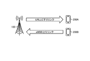
- FIG. 2 is a diagram showing an example of communication methods of eMBB and URLLC.
- the base station device 100 shown in FIG. 2 transmits a URLLC signal to the terminal device 200A using the downlink access link, and receives an eMBB signal from the terminal device 200B using the uplink access link.
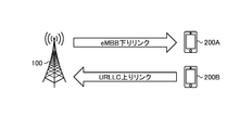
- FIG. 3 is a diagram showing another example of the communication method of eMBB and URLLC.
- the base station device 100 shown in FIG. 3 transmits an eMBB signal to the terminal device 200A using the downlink access link, and receives a URLLC signal from the terminal device 200B using the uplink access link.
- the technical problem of IBFD is interlink interference.
- the interlink interference will be described as the interference between the terminal devices 200.
- 4 and 5 are diagrams for explaining the interference between the terminal devices 200 that occurs during the IBFD operation by the base station device 100. 4 and 5 show, for example, the interference between the terminal devices 200 that occurs during the communication shown in FIGS. 2 and 3.
- the terminal device 200A transmits an uplink signal to the base station device 100, and at the same time, different terminal devices 200B in the same cell descend from the base station device 100. Receive a link signal.
- the uplink signal transmitted by the terminal device 200A interferes with the reception of the downlink signal of a different terminal device 200B.
- the base station device 100 receives an uplink signal from the terminal device 200A away from the terminal device 200B. It is necessary to search for a suitable combination of terminal devices 200. In this way, when the base station device 100 searches for an appropriate combination of the downlink terminal device 200B and the uplink terminal device 200A (terminal-terminal pairing), the base station device 100 can execute IBFD. The frequency utilization efficiency can be improved.
- FIG. 6 is a diagram for explaining the interference between the terminal devices 200 by the IBFD according to the embodiment of the present disclosure.
- inter-link interference for example, interference between terminal devices 200 and interference between base station devices 100.
- inter-link interference for example, interference between terminal devices 200 and interference between base station devices 100.
- eMBB data in the wireless layer requires a packet error rate (Block Error Rate) of 10-1 to 2 or less for an allowable delay value of several tens of milliseconds or more.
- URLLC data requires a packet error rate of 10 -3 to 5 or less for an allowable delay value within a few milliseconds.
- the terminal device 200B is a terminal device that allows the base station device 100 to transmit the eMBB data via the downlink on the IBFD. ..
- the terminal device 200C is a terminal device capable of transmitting the URLLC data by the base station device 100 via the downlink on the IBFD.
- the distance between terminals required for performing IBFD while satisfying the required reception quality of the above-mentioned eMBB data and URLLC data is the distance between the terminal devices 200A and 200C as compared with the distance between the terminal devices 200A and 200B. Is longer. That is, the amount of interference from the terminal device 200A allowed by the terminal device 200B that performs high-speed and large-capacity communication by eMBB is smaller than the amount of interference from the terminal device 200A that is allowed by the terminal device 200C that performs low-delay and high-reliability communication by URLLC. Become. Therefore, the distance between terminals capable of IBFD between URLLC and URLLC is longer than the distance between terminals capable of eMBB-eMBB. In FIG. 6, IBFD is simply described as Full Duplex.
- the base station device 100 since the required reception quality differs between eMBB and URLLC, it is difficult for the base station device 100 to uniquely determine the pairing of the terminal device 200 that performs IBFD. In such a network environment in which data with different request reception qualities coexist, in order to realize a system that satisfies all the required values, it is necessary to grasp the interference situation in more detail and to perform more precise scheduling.
- a communication device for example, a terminal device 200B
- the communication unit wirelessly communicates with a first communication device (for example, base station device 100) that supports IBFD (In Band full duplex) communication that transmits and receives wireless signals using at least a part of resources of the same frequency and the same time. I do.
- the control unit sets the channel quality between the first communication device and the first communication device based on the interference from the second communication device (for example, the terminal device 200A) that performs wireless communication with the first communication device. Measured for each level of quality of service (QoS) required for wireless communication between.
- QoS quality of service
- the base station apparatus 100 can determine the pairing of the terminal apparatus 200 that performs IBFD based on the channel quality for each QoS level, and it becomes possible to grasp the interference situation in more detail and schedule more precisely. .. Further, the frequency utilization efficiency can be further improved by the base station apparatus 100 determining the pairing of the terminal apparatus 200 performing the IBFD and performing the IBFD with the determined pairing.
- FIGS. 7 and 8. 7 and 8 are diagrams for explaining an outline of the embodiments of the present disclosure.
- the terminal device 200A measures the channel quality with and from the base station device 100 for each QoS level.
- the transmission of the uplink signal by the terminal device 200B causes interference for the terminal device 200A, which causes deterioration of the channel quality.
- the terminal device 200A measures the channel quality for each QoS level based on the desired signal from the base station device 100 and the test signal from the terminal device 200B.
- the terminal device 200A receives the eMBB desired signal from the base station device 100.
- the terminal device 200A receives the eMBB test signal from the terminal device 200B.
- the terminal device 200A measures the channel quality in the eMBB (hereinafter, also referred to as the eMBB channel quality) based on the received eMBB desired signal and the eMBB test signal.
- the terminal device 200A calculates, for example, SINR as the eMBB channel quality.
- the terminal device 200A receives the URLLC desired signal from the base station device 100.
- the terminal device 200A receives the URLLC test signal from the terminal device 200B.
- the terminal device 200A measures the channel quality in URLLC (hereinafter, also referred to as URLLC channel quality) based on the received URLLC desired signal and URLLC test signal.
- the terminal device 200A calculates, for example, SINR as the URLLC channel quality.
- the eMBB desired signal and the eMBB test signal are signals transmitted so as to satisfy the reception quality required by the eMBB, and the URLLC desired signal and the URLLC test signal are transmitted so as to satisfy the reception quality required by the URLLC. It is a signal to be made.
- the eMBB desired signal and the eMBB test signal and the URLLC desired signal and the URLLC test signal have different QoS levels.
- the terminal device 200A measures the channel quality separately for the eMBB channel quality and the URLLC channel quality. More specifically, the terminal device 200A measures the channel quality based on the eMBB desired signal and the URLLC test signal. And the channel quality based on the URLLC desired signal and the eMBB test signal is also measured.
- the terminal device 200A measures the channel quality for each combination of QoS levels.
- the terminal device 200A can report the measured channel quality to the base station device 100 for each combination of QoS levels, and the base station device 100 grasps the interference status (channel quality) for each combination of QoS levels. can do. Therefore, the base station apparatus 100 can be scheduled more precisely.
- the communication system S includes a base station device 100 and a relay device 300, and can be wirelessly connected to the terminal device 200.
- the configuration of the communication system S will be specifically described.
- FIG. 9 is a diagram showing a configuration example of the communication system S according to the embodiment of the present disclosure.
- the communication system S is a wireless communication system that provides a wireless access network to the terminal device 200.
- the communication system S is a cellular communication system using wireless access technology such as LTE (Long Term Evolution) and NR (New Radio).
- the communication system S includes a management device 400, a base station device 100, a relay device 300, and a terminal device 200.
- the communication system S provides the user with a wireless network capable of mobile communication by operating the wireless communication devices constituting the communication system S in cooperation with each other.
- the radio network of this embodiment is composed of a radio access network RAN and a core network CN.
- the wireless communication device is a device having a wireless communication function, and in the example of FIG. 9, the base station device 100, the relay device 300, and the terminal device 200 correspond to the device.
- the communication system S may include a plurality of management devices 400, a base station device 100, a relay device 300, and a terminal device 200, respectively.
- the communication system S includes management devices 400A, 10B, and the like as the management device 400.
- the communication system S includes base station devices 100A, 100B, 100C and the like as the base station device 100, and relay devices 300A, 300B and the like as the relay device 300.
- the communication system S includes terminal devices 200A, 200B, 200C and the like as the terminal device 200.
- the device in the figure may be considered as a device in a logical sense. That is, a part of the device shown in the figure may be realized by a virtual machine (VM: Virtual Machine), a container (Container), a docker (Docker), etc., and they may be mounted on physically the same hardware.
- VM Virtual Machine
- Container Container
- Docker docker
- the LTE base station device may be referred to as eNodeB (Evolved Node B) or eNB. Further, the base station apparatus of NR may be referred to as gNodeB or gNB. Further, in LTE and NR, a terminal device (also referred to as a mobile station, mobile station device, or terminal) may be referred to as a UE (User Equipment).
- the terminal device is a kind of communication device, and is also referred to as a mobile station, a mobile station device, or a terminal.
- the concept of a communication device includes not only a portable mobile device (terminal device) such as a mobile terminal, but also a device installed on a structure or a mobile body.
- the structure or the moving body itself may be regarded as a communication device.
- the concept of a communication device includes not only a terminal device but also a base station device and a relay device.
- a communication device is a type of processing device and information processing device. Further, the communication device can be paraphrased as a transmitting device (transmitting station) or a receiving device (receiving station).
- the management device 400 is a device that manages a wireless network.
- the management device 400 is a device that manages the communication of the base station device 100.
- the management device 400 is a device that functions as an MME (Mobility Management Entity), an AMF (Access and Mobility Management Function), or an SMF (Session Management Function).
- MME Mobility Management Entity
- AMF Access and Mobility Management Function
- SMF Session Management Function
- the management device 400 constitutes a core network CN together with a gateway device and the like.
- the core network CN is, for example, a network owned by a predetermined entity (subject) such as a mobile communication operator.
- the core network CN is EPC (Evolved Packet Core) or 5GC (5G Core network).
- the predetermined entity may be the same as the entity that uses, operates, and / or manages the base station apparatus 100, or may be different.
- the management device 400 may have a gateway function.
- the management device 400 may have a function as an S-GW or a P-GW.
- the management device 400 may have a function as an UPF (User Plane Function).
- the management device 400 does not necessarily have to be a device that constitutes the core network CN.
- the core network CN is a core network of W-CDMA (Wideband Code Division Multiple Access) or cdma2000 (Code Division Multiple Access 2000).
- the management device 400 may be a device that functions as an RNC (Radio Network Controller).
- RNC Radio Network Controller
- the management device 400 is connected to each of the plurality of base station devices 100 and manages the communication of the base station device 100. For example, the management device 400 determines which base station device (or which cell) the terminal device 200 is connected to, which base station device (or which cell) is in the communication area, and the like. It is grasped and managed every 200.
- the cell may be pCell (Primary Cell) or sCell (Secondary Cell).
- the cells may have different wireless resources (for example, frequency channels, component carriers, etc.) that can be used by the terminal device 200 for each cell.
- one base station apparatus may provide a plurality of cells.
- the management device 400 may be paraphrased as a control station, for example.
- the base station device 100 is a wireless communication device that wirelessly communicates with the terminal device 200.
- the base station device 100 is a type of communication device.
- the base station device 100 is, for example, a device corresponding to a radio base station (Base Station, Node B, eNB, gNB, etc.) or a radio access point (Access Point).
- the base station device 100 may be a wireless relay station.
- the base station device 100 may be a light overhanging device called an RRH (Remote Radio Head).
- the base station device 100 may be a receiving station device such as an FPU (Field Pickup Unit).
- the base station apparatus 100 is an IAB (Integrated Access and Backhaul) donor node or an IAB relay node that provides a wireless access line and a wireless backhaul line by time division multiplexing, frequency division multiplexing, or spatial division multiplexing. You may.
- IAB Integrated Access and Backhaul
- the wireless access technology used by the base station device 100 may be a cellular communication technology or a wireless LAN technology. Of course, the wireless access technology used by the base station apparatus 100 is not limited to these, and may be another wireless access technology.
- the wireless access technology used by the base station apparatus 100 may be an LPWA (Low Power Wide Area) communication technology.
- LPWA communication is communication conforming to the LPWA standard. Examples of LPWA standards include ELTRES, ZETA, SIGFOX, LoRaWAN, NB-IoT and the like. Of course, the LPWA standard is not limited to these, and other LPWA standards may be used.
- the wireless communication used by the base station apparatus 100 may be wireless communication using millimeter waves. Further, the wireless communication used by the base station device 100 may be wireless communication using radio waves, or wireless communication (optical radio) using infrared rays or visible light.
- the base station device 100 may be capable of NOMA communication with the terminal device 200.
- NOMA communication refers to communication (transmission, reception, or both) using non-orthogonal resources.
- the base station device 100 may be configured to be capable of NOMA communication with another base station device 100 and a relay device 300.
- the base station device 100 may be able to communicate with each other via an interface between the base station device and the core network (for example, S1 Interface, etc.). This interface may be wired or wireless. Further, the base station devices 100 may be able to communicate with each other via an interface between the base station devices (for example, X2 Interface, Xn Interface, S1 Interface, etc.). This interface may be wired or wireless.
- the base station device 100 can be used, operated, and / or managed by various entities.
- the entities include a mobile network operator (MNO: Mobile Network Operator), a virtual mobile network operator (MVNO: Mobile Virtual Network Operator), a virtual mobile communication enabler (MVNE: Mobile Virtual Network Enabler), and a neutral host.
- MNO Mobile Network Operator
- MVNO Mobile Virtual Network Operator
- MVNE Virtual Mobile Network Enabler
- NTN Neutral Host Network
- operators enterprises, educational institutions (school corporations, local government education committees, etc.), real estate (buildings, condominiums, etc.) managers, individuals, etc. can be assumed.
- the base station apparatus 100 may be installed and / or operated by one business operator, or may be installed and / or operated by one individual.
- the installation / operation entity of the base station device 100 is not limited to these.
- the base station device 100 may be jointly installed and operated by a plurality of businesses or a plurality of individuals.
- the base station device 100 may be a shared facility used by a plurality of businesses or a plurality of individuals. In this case, the installation and / or operation of the equipment may be carried out by a third party different from the user.
- a base station device also referred to as a base station
- a base station device includes not only a donor base station but also a relay base station (also referred to as a relay device or a relay device device).
- a relay base station also referred to as a relay device or a relay device device.
- the concept of a base station includes not only a structure having a function of a base station but also a device installed in the structure.
- Structures are, for example, high-rise buildings, houses, steel towers, station facilities, airport facilities, port facilities, stadiums, and other buildings.
- the concept of structure includes not only buildings but also non-building structures such as tunnels, bridges, dams, walls, and iron pillars, and equipment such as cranes, gates, and windmills.
- the concept of a structure includes not only structures on land (above ground in a narrow sense) or underground, but also structures on water such as piers and mega floats, and structures underwater such as ocean observation equipment.
- the base station device can be rephrased as a processing device or an information processing device.
- the base station device 100 may be a donor station or a relay station (relay device). Further, the base station device 100 may be a fixed station or a mobile station.
- the mobile station is a wireless communication device (for example, a base station device) configured to be movable. At this time, the base station device 100 may be a device installed on the mobile body or may be the mobile body itself.
- a relay station device having mobility can be regarded as a base station device 100 as a mobile station.
- devices such as vehicles, drones, and smartphones that are originally capable of moving and that are equipped with the functions of the base station device (at least a part of the functions of the base station device) are also included in the base station device 100 as a mobile station. Applicable.
- the mobile body may be a mobile terminal such as a smartphone or a mobile phone.
- the moving body may be a moving body (for example, a vehicle such as a car, a bicycle, a bus, a truck, a motorcycle, a train, a linear motor car, etc.) that moves on land (ground in a narrow sense), or in the ground (for example, a vehicle).
- a moving body for example, a subway moving in a tunnel.
- the moving body may be a moving body moving on the water (for example, a ship such as a passenger ship, a cargo ship, a hovercraft, etc.), or a moving body moving underwater (for example, a submersible, a submarine, an unmanned submarine, etc.). Submersible).
- the moving body may be a moving body moving in the atmosphere (for example, an aircraft such as an airplane, an airship, or a drone), or a moving body moving outside the atmosphere (for example, an artificial satellite, a spacecraft, or a space station).
- a moving body moving outside the atmosphere for example, an artificial satellite, a spacecraft, or a space station.
- An artificial celestial body such as a spacecraft.
- a moving body that moves outside the atmosphere can be rephrased as a space moving body.
- the base station device 100 may be a ground base station device (ground station device) installed on the ground.
- the base station device 100 may be a base station device arranged on a structure on the ground, or may be a base station device installed on a mobile body moving on the ground.
- the base station device 100 may be an antenna installed in a structure such as a building and a signal processing device connected to the antenna.
- the base station device 100 may be a structure or a moving body itself. "Ground" is not only on land (ground in a narrow sense) but also on the ground in a broad sense including underground, water, and water.
- the base station device 100 is not limited to the ground base station device.
- the base station device 100 may be a non-ground base station device (non-ground station device) capable of floating in the air or in space.
- the base station device 100 may be an aircraft station device or a satellite station device.
- the aircraft station device is a wireless communication device that can float in the atmosphere such as an aircraft.
- the aircraft station device may be a device mounted on an aircraft or the like, or may be an aircraft itself.
- the concept of an aircraft includes not only heavy aircraft such as airplanes and gliders, but also light aircraft such as balloons and airships.
- the concept of an aircraft includes not only heavy aircraft and light aircraft, but also rotary-wing aircraft such as helicopters and autogyros.
- the aircraft station device (or the aircraft on which the aircraft station device is mounted) may be an unmanned aerial vehicle such as a drone.
- unmanned aerial vehicle also includes unmanned aerial vehicles (UAS: Unmanned Aircraft Systems) and tethered unmanned aerial vehicles (tethered UAS).
- UAS Unmanned Aircraft Systems
- tethered UAS tethered unmanned aerial vehicles
- unmanned aerial vehicle includes a light unmanned aerial vehicle system (LTA: Lighter than Air UAS) and a heavy unmanned aerial vehicle system (HTA: Heavier than Air UAS).
- HAPs High Altitude UAS Platforms
- the satellite station device is a wireless communication device that can float outside the atmosphere.
- the satellite station device may be a device mounted on a space mobile body such as an artificial satellite, or may be a space mobile body itself.
- the satellites that serve as satellite station equipment are low orbit (LEO: Low Earth Orbiting) satellites, medium orbit (MEO: Medium Earth Orbiting) satellites, stationary (GEO: Geostationary Earth Orbiting) satellites, and high elliptical orbit (HEO: Highly Elliptical Orbiting). It may be any satellite.
- the satellite station device may be a device mounted on a low earth orbit satellite, a medium earth orbit satellite, a geostationary satellite, or a high elliptical orbit satellite.
- the size of the coverage of the base station apparatus 100 may be from a large one such as a macro cell to a small one such as a pico cell. Of course, the size of the coverage of the base station apparatus 100 may be extremely small, such as a femtocell. Further, the base station apparatus 100 may have a beamforming capability. In this case, the base station apparatus 100 may form a cell or a service area for each beam.
- the base station device 100A is connected to the relay device 300A, and the base station device 100B is connected to the relay device 300B.
- the base station device 100A can indirectly wirelessly communicate with the terminal device 200 via the relay device 300A.
- the base station device 100A can indirectly wirelessly communicate with the terminal device 200 via the relay device 300A.
- the relay device 300 is a device that serves as a relay device for the base station.
- the relay device 300 is a type of base station device.
- the relay device can be rephrased as a relay base station device (or a relay base station).
- the relay device 300 can perform NOMA communication with the terminal device 200.
- the relay device 300 relays the communication between the base station device 100 and the terminal device 200.
- the relay device 300 may be configured to enable NOMA communication with another relay device 300 and the base station device 100.
- the relay device 300 may be a ground station device or a non-ground station device.
- the relay device 300 and the base station device 100 form a radio access network RAN.
- the relay device 300 is a device that transmits information from one communication device to the other communication device. Specifically, it is a device that receives a signal from one communication device and transmits the signal to the other communication device. It is assumed that the relay device 300 communicates wirelessly between one communication device and the relay device 300, and between the relay device 300 and the other communication device.
- the relay device 30 may be a fixed device, a movable device, or a floating device.
- the relay device 300 is not limited to the size of coverage.
- the relay device 300 may be a macro cell, a micro cell, or a small cell. Further, the relay device 300 is not limited to the device to be mounted as long as the relay function is satisfied.
- the relay device 300 may be mounted on a terminal device 200 such as a smartphone, a car or a rickshaw, a balloon, an airplane, a drone, a television, a game machine, or the like. It may be installed in home appliances such as air conditioners, refrigerators, and lighting fixtures.
- a terminal device 200 such as a smartphone, a car or a rickshaw, a balloon, an airplane, a drone, a television, a game machine, or the like. It may be installed in home appliances such as air conditioners, refrigerators, and lighting fixtures.
- the terminal device 200 is a wireless communication device that wirelessly communicates with the base station device 100 or the relay device 30.
- the terminal device 200 is, for example, a mobile phone, a smart device (smartphone or tablet), a PDA (Personal Digital Assistant), or a personal computer.
- the terminal device 200 may be a device such as a commercial camera provided with a communication function, or may be a motorcycle, a mobile relay vehicle, or the like equipped with a communication device such as an FPU (Field Pickup Unit). ..
- the terminal device 200 may be an M2M (Machine to Machine) device or an IoT (Internet of Things) device.
- the terminal device 200 may be capable of side link communication with another terminal device 200.
- the terminal device 200 may be able to use an automatic retransmission technique such as HARQ when performing side link communication.
- the terminal device 200 may be capable of NOMA communication with the base station device 100 and the relay device 300.
- the terminal device 200 may also be capable of NOMA communication in communication (side link) with another terminal device 200.
- the terminal device 200 may be capable of LPWA communication with other communication devices (for example, the base station device 100, the relay device 300, and the other terminal device 200).
- the wireless communication used by the terminal device 200 may be wireless communication using millimeter waves.
- the wireless communication (including side link communication) used by the terminal device 200 may be wireless communication using radio waves or wireless communication using infrared rays or visible light (optical radio). good.
- the terminal device 200 may be a mobile device.
- the mobile device is a mobile wireless communication device.
- the terminal device 200 may be a wireless communication device installed on the mobile body or may be the mobile body itself.
- the terminal device 200 may be a vehicle (Vehicle) moving on the road such as an automobile, a bus, a truck, or a motorcycle, or a wireless communication device mounted on the vehicle.
- the moving body may be a mobile terminal, or may be a moving body that moves on land (ground in a narrow sense), in the ground, on the water, or in the water.
- the moving body may be a moving body that moves in the atmosphere such as a drone or a helicopter, or may be a moving body that moves outside the atmosphere such as an artificial satellite.
- the terminal device 200 may be connected to a plurality of base station devices or a plurality of cells at the same time to perform communication.
- a plurality of cells for example, pCell, sCell
- CA Carrier Aggregation
- DC Dual Connectivity
- MC multi-connectivity
- the terminal device 200 and the plurality of base station devices 100 can communicate with each other through the cells of different base station devices 100 by the coordinated transmission / reception (CoMP: Coordinated Multi-Point Transmission and Reception) technology.
- CoMP Coordinated Multi-Point Transmission and Reception
- the terminal device 200 does not necessarily have to be a device directly used by a person.
- the terminal device 200 may be a sensor installed in a machine or the like in a factory, such as a so-called MTC (Machine Type Communication).
- the terminal device 200 may be an M2M (Machine to Machine) device or an IoT (Internet of Things) device.
- the terminal device 200 may be a device having a relay communication function, as typified by D2D (Device to Device) and V2X (Vehicle to everything).
- the terminal device 200 may be a device called CPE (Client Premises Equipment) used in a wireless backhaul or the like.
- CPE Customer Premises Equipment
- each device constituting the communication system S according to the embodiment will be specifically described.
- the configuration of each device shown below is just an example.
- the configuration of each device may differ from the configuration below.
- FIG. 10 is a diagram showing a configuration example of the management device 400 according to the embodiment of the present disclosure.
- the management device 400 is a device that manages a wireless network.
- the management device 400 includes a communication unit 41, a storage unit 42, and a control unit 43.
- the configuration shown in FIG. 10 is a functional configuration, and the hardware configuration may be different from this. Further, the functions of the management device 400 may be distributed and implemented in a plurality of physically separated configurations.
- the management device 400 may be composed of a plurality of server devices.
- the communication unit 41 is a communication interface for communicating with other devices.
- the communication unit 41 may be a network interface or a device connection interface.
- the communication unit 41 may be a LAN (Local Area Network) interface such as a NIC (Network Interface Card), or a USB interface composed of a USB (Universal Serial Bus) host controller, a USB port, or the like. May be good.
- the communication unit 41 may be a wired interface or a wireless interface.
- the communication unit 41 functions as a communication means of the management device 400.
- the communication unit 41 communicates with the base station device 100 according to the control of the control unit 13.
- the storage unit 42 is a storage device capable of reading and writing data such as DRAM (Dynamic Random Access Memory), SRAM (Static Random Access Memory), flash memory, and hard disk.
- the storage unit 42 functions as a storage means for the management device 400.
- the storage unit 42 stores, for example, the connection state of the terminal device 200.
- the storage unit 42 stores the state of the RRC (Radio Resource Control) and the state of the ECM (EPS Connection Management) of the terminal device 200.
- the storage unit 42 may function as a home memory for storing the position information of the terminal device 200.
- the control unit 43 is a controller that controls each unit of the management device 400.
- the control unit 43 is realized by, for example, a processor such as a CPU (Central Processing Unit) or an MPU (Micro Processing Unit).
- the control unit 43 is realized by the processor executing various programs stored in the storage device inside the management device 400 using a RAM (Random Access Memory) or the like as a work area.
- the control unit 43 may be realized by an integrated circuit such as an ASIC (Application Specific Integrated Circuit) or an FPGA (Field Programmable Gate Array).
- the CPU, MPU, ASIC, and FPGA can all be regarded as controllers.
- FIG. 11 is a diagram showing a configuration example of the base station device 100 according to the embodiment of the present disclosure.
- the base station device 100 supports a 2-step random access procedure in addition to the conventional 4-step random access procedure (contention-based random access procedure) and 3-step random access procedure (non-contention-based random access procedure). .. Further, the base station device 100 can perform NOMA communication with the terminal device 200.
- the base station device 100 includes a signal processing unit 11, a storage unit 12, and a control unit 13.
- the configuration shown in FIG. 11 is a functional configuration, and the hardware configuration may be different from this. Further, the functions of the base station apparatus 100 may be distributed and implemented in a plurality of physically separated configurations.
- the signal processing unit 11 is a signal processing unit for wireless communication with another wireless communication device (for example, a terminal device 200, a relay device 30).
- the signal processing unit 11 operates according to the control of the control unit 13.
- the signal processing unit 11 corresponds to one or more wireless access methods.
- the signal processing unit 11 corresponds to both NR and LTE.
- the signal processing unit 11 may support W-CDMA and cdma2000 in addition to NR and LTE. Further, the signal processing unit 11 supports communication using NOMA.
- the signal processing unit 11 includes a reception processing unit 111, a transmission processing unit 112, an antenna 113, and a self-canceller unit 114.
- the signal processing unit 11 may include a plurality of reception processing units 111, transmission processing units 112, antennas 113, and self-canceller units 114, respectively.
- each unit of the signal processing unit 11 may be individually configured for each wireless access method.
- the reception processing unit 111 and the transmission processing unit 112 may be individually configured by LTE and NR.
- the reception processing unit 111 processes the uplink signal received via the antenna 113.
- the reception processing unit 111 includes a wireless reception unit 111a, a multiple separation unit 111b, a demodulation unit 111c, and a decoding unit 111d.
- the wireless receiver 111a performs down-conversion, removal of unnecessary frequency components, control of amplification level, orthogonal demodulation, conversion to digital signal, removal of guard interval (cyclic prefix), and fast Fourier transform for the uplink signal.
- the frequency domain signal is extracted by.
- the multiplex separation unit 111b separates uplink channels such as PUSCH (Physical Uplink Shared Channel) and PUCCH (Physical Uplink Control Channel) and uplink reference signals from the signal output from the wireless reception unit 111a.
- the demodulation unit 111c demodulates the received signal with respect to the modulation symbol of the uplink channel by using a modulation method such as BPSK (Binary Phase Shift Keying) or QPSK (Quadrature Phase shift Keying).
- BPSK Binary Phase Shift Keying
- QPSK Quadrature Phase shift Keying
- the modulation method used by the demodulation unit 111c may be 16QAM (Quadrature Amplitude Modulation), 64QAM, or 256QAM. In this case, the signal points on the constellation do not necessarily have to be equidistant.
- the constellation may be a non-uniform constellation (NUC: Non Uniform Constellation).
- the decoding unit 111d performs decoding processing on the coded bits of the demodulated uplink channel. The decoded uplink data and uplink control information are output to the control unit 13.
- the transmission processing unit 112 performs transmission processing of downlink control information and downlink data.
- the transmission processing unit 112 includes a coding unit 112a, a modulation unit 112b, a multiplexing unit 112c, and a wireless transmission unit 112d.
- the coding unit 112a encodes the downlink control information and the downlink data input from the control unit 13 by using a coding method such as block coding, convolutional coding, or turbo coding.
- the modulation unit 112b modulates the coding bits output from the coding unit 112a by a predetermined modulation method such as BPSK, QPSK, 16QAM, 64QAM, 256QAM and the like. In this case, the signal points on the constellation do not necessarily have to be equidistant.
- the constellation may be a non-uniform constellation.
- the multiplexing unit 112c multiplexes the modulation symbol of each channel and the downlink reference signal and arranges them in a predetermined resource element.
- the wireless transmission unit 112d performs various signal processing on the signal from the multiplexing unit 112c.
- the radio transmitter 112d converts to the time domain by fast Fourier transform, adds a guard interval (cyclic prefix), generates a baseband digital signal, converts to an analog signal, orthogonal transforms, up-converts, and extras. Performs processing such as removing frequency components and amplifying power.
- the signal generated by the transmission processing unit 112 is transmitted from the antenna 113.
- the self-canceller unit 114 cancels the self-interference in which the signal transmitted by the wireless transmission unit 112d leaks into the wireless reception unit 111a.
- the storage unit 12 is a storage device that can read and write data such as DRAM, SRAM, flash memory, and hard disk.
- the storage unit 12 functions as a storage means for the base station device 100.
- the control unit 13 is a controller that controls each unit of the base station device 100.
- the control unit 13 is realized by, for example, a processor such as a CPU (Central Processing Unit) or an MPU (Micro Processing Unit).
- the control unit 13 is realized by the processor executing various programs stored in the storage device inside the base station device 100 using a RAM (Random Access Memory) or the like as a work area.
- the control unit 13 may be realized by an integrated circuit such as an ASIC (Application Specific Integrated Circuit) or an FPGA (Field Programmable Gate Array).
- the CPU, MPU, ASIC, and FPGA can all be regarded as controllers.
- the control unit 13 includes a determination unit 131.
- the blocks (determination unit 131) constituting the control unit 13 are functional blocks indicating the functions of the control unit 13, respectively.
- These functional blocks may be software blocks or hardware blocks.
- each of the above-mentioned functional blocks may be one software module realized by software (including a microprocessor) or one circuit block on a semiconductor chip (die).
- each functional block may be one processor or one integrated circuit.
- the method of configuring the functional block is arbitrary.
- control unit 13 may be configured in a functional unit different from the above-mentioned functional block.
- the operation of the block (determination unit 131) constituting the control unit 13 will be described later.
- FIG. 12 is a diagram showing a configuration example of the relay device 300 according to the embodiment of the present disclosure.
- the relay device 300 can perform NOMA communication with the terminal device 200.
- the relay device 300 includes a signal processing unit 31, a storage unit 32, a network communication unit 33, and a control unit 34.
- the configuration shown in FIG. 12 is a functional configuration, and the hardware configuration may be different from this. Further, the functions of the relay device 300 may be distributed and implemented in a plurality of physically separated configurations.
- the signal processing unit 31 is a signal processing unit for wireless communication with other wireless communication devices (for example, the base station device 100 and the terminal device 200).
- the signal processing unit 31 operates according to the control of the control unit 34.
- the signal processing unit 31 includes a reception processing unit 311, a transmission processing unit 312, an antenna 313, and a self-canceller unit 314.
- the configuration of the signal processing unit 31, the reception processing unit 311, the transmission processing unit 312, and the antenna 313 includes the signal processing unit 21, the reception processing unit 211, the transmission processing unit 212, the antenna 213, and the self-canceller unit 214 of the base station apparatus 100. The same is true.
- the storage unit 32 is a storage device that can read and write data such as DRAM, SRAM, flash memory, and hard disk.
- the storage unit 32 functions as a storage means for the relay device 300.
- the configuration of the storage unit 32 is the same as that of the storage unit 22 of the base station apparatus 100.
- the network communication unit 33 is a communication interface for communicating with other devices.
- the network communication unit 33 is a LAN interface such as a NIC.
- the network communication unit 33 may be a wired interface or a wireless interface.
- the network communication unit 33 functions as a network communication means of the relay device 300.
- the network communication unit 33 communicates with the base station device 100 according to the control of the control unit 34.
- the control unit 34 is a controller that controls each unit of the relay device 300.
- the configuration of the control unit 34 may be the same as that of the control unit 23 of the base station apparatus 100.
- the control unit 34 includes a determination unit 341.
- the control unit 34 may be configured in a functional unit different from the above-mentioned functional block.
- FIG. 13 is a diagram showing a configuration example of the terminal device 200 according to the embodiment of the present disclosure.
- the terminal device 200 can use a 2-step random access procedure in addition to the conventional 4-step random access procedure (contention-based random access procedure) and 3-step random access procedure (non-contention-based random access procedure). be.
- the terminal device 200 can perform NOMA communication with the base station device 100 and the relay device 30.
- the terminal device 200 includes a signal processing unit 21, a storage unit 22, a network communication unit 23, an input / output unit 24, and a control unit 25.
- the configuration shown in FIG. 13 is a functional configuration, and the hardware configuration may be different from this. Further, the functions of the terminal device 200 may be distributed and implemented in a plurality of physically separated configurations.
- the signal processing unit 21 is a signal processing unit for wireless communication with other wireless communication devices (for example, the base station device 100 and the relay device 30).
- the signal processing unit 21 operates according to the control of the control unit 25.
- the signal processing unit 21 corresponds to one or more wireless access methods.
- the signal processing unit 21 corresponds to both NR and LTE.
- the signal processing unit 21 may support W-CDMA and cdma2000 in addition to NR and LTE. Further, the signal processing unit 21 supports communication using NOMA.
- the signal processing unit 21 includes a reception processing unit 211, a transmission processing unit 212, an antenna 213, and a self-canceller unit 214.
- the signal processing unit 21 may include a plurality of reception processing units 211, transmission processing units 212, antennas 213, and self-canceller units 214, respectively.
- each unit of the signal processing unit 21 may be individually configured for each wireless access method.
- the reception processing unit 211 and the transmission processing unit 212 may be individually configured by LTE and NR.
- the reception processing unit 211 processes the downlink signal received via the antenna 213.
- the reception processing unit 211 includes a wireless reception unit 211a, a multiple separation unit 211b, a demodulation unit 211c, and a decoding unit 211d.
- the wireless receiver 211a down-converts the downlink signal, removes unnecessary frequency components, controls the amplification level, quadrature demodulates, converts to a digital signal, removes the guard interval (cyclic prefix), and performs a fast Fourier transform.
- the frequency domain signal is extracted by.
- the multiplex separation unit 211b separates the downlink channel, the downlink synchronization signal, and the downlink reference signal from the signal output from the radio reception unit 211a.
- the downlink channel is, for example, a channel such as PBCH (Physical Broadcast Channel), PDSCH (Physical Downlink Shared Channel), PDCCH (Physical Downlink Control Channel).
- the demodulation unit 211c demodulates the received signal with respect to the modulation symbol of the downlink channel by using a modulation method such as BPSK, QPSK, 16QAM, 64QAM, 256QAM. In this case, the signal points on the constellation do not necessarily have to be equidistant.
- the constellation may be a non-uniform constellation.
- the decoding unit 211d performs decoding processing on the coded bits of the demodulated downlink channel. The decoded downlink data and downlink control information are output to the control unit 25.
- the transmission processing unit 212 performs the transmission processing of the uplink control information and the uplink data.
- the transmission processing unit 212 includes a coding unit 212a, a modulation unit 212b, a multiplexing unit 212c, and a wireless transmission unit 212d.
- the coding unit 212a encodes the uplink control information and the uplink data input from the control unit 25 by using a coding method such as block coding, convolutional coding, or turbo coding.
- the modulation unit 212b modulates the coding bits output from the coding unit 212a by a predetermined modulation method such as BPSK, QPSK, 16QAM, 64QAM, 256QAM and the like. In this case, the signal points on the constellation do not necessarily have to be equidistant.
- the constellation may be a non-uniform constellation.
- the multiplexing unit 212c multiplexes the modulation symbol of each channel and the uplink reference signal and arranges them in a predetermined resource element.
- the wireless transmission unit 212d performs various signal processing on the signal from the multiplexing unit 212c.
- the radio transmitter 212d converts to the time domain by inverse fast Fourier transform, adds a guard interval (cyclic prefix), generates a baseband digital signal, converts to an analog signal, orthogonal modulation, up-conversion, and extra. Performs processing such as removal of various frequency components and amplification of power.
- the signal generated by the transmission processing unit 212 is transmitted from the antenna 213.
- the self-canceller unit 214 cancels the self-interference in which the signal transmitted by the wireless transmission unit 212d leaks into the wireless reception unit 211a.
- the storage unit 22 is a data-readable / writable storage device such as a DRAM, SRAM, flash memory, and hard disk. The storage unit 22 functions as a storage means for the terminal device 200.
- the network communication unit 23 is a communication interface for communicating with other devices.
- the network communication unit 23 is a LAN interface such as a NIC.
- the network communication unit 23 may be a wired interface or a wireless interface.
- the network communication unit 23 functions as a network communication means of the terminal device 200.
- the network communication unit 23 communicates with other devices according to the control of the control unit 25.
- the input / output unit 24 is a user interface for exchanging information with the user.
- the input / output unit 24 is an operation device for a user to perform various operations such as a keyboard, a mouse, operation keys, and a touch panel.
- the input / output unit 24 is a display device such as a liquid crystal display (Liquid Crystal Display) or an organic EL display (Organic Electroluminescence Display).
- the input / output unit 24 may be an audio device such as a speaker or a buzzer.
- the input / output unit 24 may be a lighting device such as an LED (Light Emitting Diode) lamp.
- the input / output unit 24 functions as an input / output means (input means, output means, operation means, or notification means) of the terminal device 200.
- the control unit 25 is a controller that controls each unit of the terminal device 200.
- the control unit 25 is realized by, for example, a processor such as a CPU or MPU.
- the control unit 25 is realized by the processor executing various programs stored in the storage device inside the terminal device 200 with the RAM or the like as a work area.
- the control unit 25 may be realized by an integrated circuit such as an ASIC or FPGA.
- the CPU, MPU, ASIC, and FPGA can all be regarded as controllers.
- the control unit 25 includes a measurement unit 251 and a reporting unit 252.
- Each block (measurement unit 251 and reporting unit 252) constituting the control unit 25 is a functional block indicating the function of the control unit 25, respectively.
- These functional blocks may be software blocks or hardware blocks.
- each of the above-mentioned functional blocks may be one software module realized by software (including a microprocessor) or one circuit block on a semiconductor chip (die).
- each functional block may be one processor or one integrated circuit. The method of configuring the functional block is arbitrary.
- control unit 25 may be configured in a functional unit different from the above-mentioned functional block. The operation of each block (measurement unit 251 and reporting unit 252) constituting the control unit 25 will be described later.
- the base station apparatus 100 appearing in the following description typically assumes a base station such as eNB or gNB, but of course, the base station apparatus 100 is not limited to eNB or gNB.
- the base station device 100 may be a relay terminal or a terminal such as a reader terminal in a terminal group.
- the base station apparatus 100 includes ⁇ 3.1. It may be the device (or system) exemplified in the overall configuration of the communication system> or the like.
- the description of the base station device 100 appearing in the following description can be replaced with the "relay device 300" or the "terminal device 100".
- resource includes Frequency, Time, Resource Element, Resource Block, Bandwidth Part, Component Carrier, Symbol, Sub-Symbol, Slot, Mini-Slot, Subframe, Frame, PRACH Occasion, Occasion, Code, Multi. -Access physical resource, Multi-access signature, etc. are included.
- resources are not limited to these.
- the assumed system of the communication system S has a base station device and a terminal device, and wirelessly communicates between the base station device and the terminal device, for example, different QoS (Quality of Service) between the eMBB signal and the URLLC signal.
- QoS Quality of Service
- the length of allocated resources differs between the eMBB signal and the URLLC signal. Specifically, the length of the channel (PDSCH / PUSCH / PUCCH, etc.) assigned to the URLLC signal tends to be shorter than the length of the channel assigned to the eMBB signal.
- the CQI (Channel Quality Indicator) table is different between the eMBB signal and the URLLC signal.
- the CQI table applied to the eMBB signal contains a large amount of high efficiency modulation and code rate
- the CQI table applied to the URLLC signal contains a large amount of low efficiency modulation and code rate.
- the CQI table applied to the eMBB signal includes 256QAM
- the CQI table applied to the URLLC signal does not include 256QAM.
- the CQI error rate table applied to the eMBB signal is more efficient for the same index.
- the MCS (Modulation and Coding Scheme) table is different between the eMBB signal and the URLLC signal.
- the MCS table applied to the eMBB signal contains a large amount of high efficiency modulation and code rate
- the MCS table applied to the URLLC signal contains a large amount of low efficiency modulation and code rate.
- the MCS table applied to the eMBB signal is more efficient in the case of the same index.
- the eMBB signal and the URLLC signal differ in the presence or absence of the repeat transmission setting.
- the repetitive transmission setting is not applied to the eMBB signal, and the repetitive transmission setting using a plurality of resources is applied to the URLLC signal.
- the PDSCH / PUSCH mapping type differs between the eMBB signal and the URLLC signal.
- slot-based scheduling (PDSCH / PUSCH mapping type A) is applied to eMBB signals
- non-slot-based scheduling (PDSCH / PUSCH mapping type B) tends to be applied to URLLC signals.
- Slot-based scheduling is a method in which resources are allocated from the beginning of a slot on the time axis
- non-slot-based scheduling is a method in which resources can be allocated from the middle of a slot on the time axis.
- the bandwidth part (BWP: Bandwidth Part) used differs between the eMBB signal and the URLLC signal.
- One or more bandwidth parts are set in the terminal device.
- One predetermined numerology (subcarrier interval and symbol length) is set in the bandwidth part.
- a bandwidth part set with a numerology having a narrow subcarrier interval and a long symbol length (for example, a subcarrier interval of 15 kHz or 30 kHz in FR1) is used.
- a bandwidth part set with a numerology having a wide subcarrier interval and a short symbol length (for example, a subcarrier interval of 30 kHz or 60 kHz in FR1) is used.
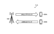
- FIG. 14 is a diagram showing a configuration example of the assumed system S_A according to the embodiment of the present disclosure.
- FIG. 14 shows a case where the base station apparatus 100 supports IBFD.
- the base station device 100 Since the base station device 100 is capable of IBFD operation, it is possible to receive the wireless signal on the uplink from the terminal device 200B while transmitting the wireless signal to the terminal device 200A on the downlink using the same resource.
- the base station apparatus 100 transmits a URLLC signal as a downlink signal.
- the downlink that performs such transmission is also referred to as a URLLC downlink.
- the base station apparatus 100 receives an eMBB signal as an uplink signal.
- the uplink that performs such reception is also referred to as an eMBB uplink.
- the base station device 100 multiplexes the eMBB uplink and the URLLC downlink for the two terminal devices 200A and 200B.
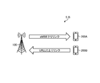
- FIG. 15 is a diagram showing a configuration example of the assumed system S_B according to the embodiment of the present disclosure.
- FIG. 15 shows a case where the base station apparatus 100 is compatible with IBFD, as in FIG.
- the base station apparatus 100 transmits an eMBB signal as a downlink signal.
- the downlink that performs such transmission is also referred to as an eMBB downlink.
- the base station apparatus 100 receives a URLLC signal as an uplink signal.
- the uplink that performs such reception is also referred to as a URLLC uplink.
- the base station device 100 multiplexes the URLLC uplink and the eMBB downlink for the two terminal devices 200A and 200B.
- FIG. 16 is a diagram showing a configuration example of the assumed system S_C according to the embodiment of the present disclosure.
- FIG. 16 shows a case where the base station device 100 and the terminal device 200 support IBFD.
- the base station device 100 Since the base station device 100 and the terminal device 200 are capable of IBFD operation, the base station device 100 sends a radio signal from the base station device 100 to the terminal device 200 via a downlink using the same resources, and the terminal device 200 to the base station device 100 Radio signals can be transmitted over the uplink.
- the base station apparatus 100 transmits a URLLC signal as a downlink signal. Further, the base station apparatus 100 receives an eMBB signal as an uplink signal. The base station device 100 multiplexes the eMBB uplink and the URLLC downlink for one terminal device 200.
- FIG. 17 is a diagram showing a configuration example of the assumed system S_D according to the embodiment of the present disclosure.
- FIG. 17 shows a case where the base station device 100 and the terminal device 200 are compatible with IBFD, as in FIG.
- the base station apparatus 100 transmits an eMBB signal as a downlink signal.
- the base station apparatus 100 receives a URLLC signal as an uplink signal.
- the base station device 100 multiplexes the URLLC uplink and the eMBB downlink for one terminal device 200.
- FIG. 18 is a diagram showing a configuration example of the assumed system S_E according to the embodiment of the present disclosure.
- FIG. 18 shows a case where the relay device (relay) 300 is compatible with IBFD.
- the relay device 300 Since the relay device 300 can operate in IBFD, the relay device 300 uses the same resource to receive the wireless signal on the downlink backhaul link from the base station apparatus 100, and transmits the wireless signal to the terminal device 200 on the downlink access link. Can be done.
- the relay device 300 receives the eMBB signal from the base station device 100. Further, the relay device 300 transmits the URLLC signal to the terminal device 200 by using the same resource as the reception of the eMBB signal from the base station device 100. The relay device 300 multiplexes the eMBB downlink backhaul link and the URLLC downlink access link for one base station device 100 and one terminal device 200.
- FIG. 19 is a diagram showing a configuration example of the assumed system S_F according to the embodiment of the present disclosure.
- FIG. 19 shows a case where the relay device 300 is compatible with IBFD, as in FIG. In FIG. 19, the relay device 300 receives the URLLC signal from the base station device 100. Further, the relay device 300 transmits the eMBB signal to the terminal device 200 by using the same resource as the reception of the eMBB signal from the base station device 100. The relay device 300 multiplexes the URLLC downlink backhaul link and the eMBB downlink access link for one base station device 100 and one terminal device 200.
- FIG. 20 is a diagram showing a configuration example of the assumed system S_G according to the embodiment of the present disclosure.
- FIG. 20 shows a case where the relay device 300 is compatible with IBFD, as in FIGS. 18 and 19.
- the same resource is used to transmit a wireless signal to the base station device 100 via an uplink backhaul link, while receiving a wireless signal from the terminal device 200 via an uplink access link.
- the relay device 300 receives the URLLC signal from the terminal device 200. Further, the relay device 300 transmits the eMBB signal to the base station device 100 by using the same resource as the reception of the URLLC signal from the terminal device 200. The relay device 300 multiplexes the eMBB uplink backhaul link and the URLLC uplink access link for one base station device 100 and one terminal device 200.
- FIG. 21 is a diagram showing a configuration example of the assumed system S_H according to the embodiment of the present disclosure.
- FIG. 21 shows a case where the relay device 300 is compatible with IBFD, as in FIGS. 18 to 20.
- the relay device 300 receives the eMBB signal from the terminal device 200. Further, the relay device 300 transmits the URLLC signal to the base station device 100 using the same resources as the reception of the eMBB signal from the terminal device 200.
- the relay device 300 multiplexes the URLLC uplink backhaul link and the eMBB uplink access link for one base station device 100 and one terminal device 200.
- the relay device 300 relays the base station device 100 and the terminal device 200, but the present invention is not limited to this.
- the relay device 300 may relay between the base station device 100 and another relay device 300, or between the other relay devices 300.
- the relay device 300 is a kind of the base station device 100, but the present invention is not limited to this.
- the relay device 300 may be a kind of terminal device 200.
- the communication between the relay device 300 and the terminal device 200 may be side link communication.
- FIG. 22 is a diagram showing a configuration example of the assumed system S_I according to the embodiment of the present disclosure.
- FIG. 22 shows a case where the base station device 100 and the relay device (relay) 300 are compatible with IBFD.
- the base station device 100 uses the same resources to transmit a radio signal to the relay device 300 via a downlink backhaul link while moving up from the relay device 300. Radio signals can be received on the backhaul link.
- the relay device 300 receives the URLLC signal from the base station device 100. Further, the relay device 300 transmits the eMBB signal to the base station device 100 by using the same resource as the reception of the URLLC signal from the base station device 100.
- the base station apparatus 100 multiplexes the eMBB uplink backhaul link and the URLLC downlink backhaul link for one relay device 300.
- FIG. 23 is a diagram showing a configuration example of the assumed system S_J according to the embodiment of the present disclosure.
- FIG. 23 shows a case where the base station device 100 and the relay device 300 are compatible with IBFD, as in FIG. 22.
- the relay device 300 receives the eMBB signal from the base station device 100. Further, the relay device 300 transmits the URLLC signal to the base station device 100 by using the same resource as the reception of the eMBB signal from the base station device 100.
- the base station device 100 multiplexes the URLLC uplink backhaul link and the eMBB downlink backhaul link for one relay device 300.
- FIG. 24 is a diagram showing a configuration example of the assumed system S_K according to the embodiment of the present disclosure.
- FIG. 43 shows a case where the terminal device 200 supports IBFD.
- the terminal device 200 Since the terminal device 200 is capable of IBFD operation, the terminal device 200 uses the same resource to transmit a wireless signal to the base station device 100A via the uplink access link, while transmitting the wireless signal from the base station device 100B to the base station device 100B via the downlink access link. Can be received.
- the terminal device 200 transmits a URLLC signal to the base station device 100A. Further, the terminal device 200 receives the eMBB signal from the base station device 100B by using the same resource as the transmission of the URLLC signal to the base station device 100A. The terminal device 200 multiplexes the URLLC uplink access link and the eMBB downlink access link for the two base station devices 100A and 100B.
- TRP Transmission and Reception Point
- FIG. 25 is a diagram showing a configuration example of the assumed system S_L according to the embodiment of the present disclosure.
- FIG. 25 shows a case where the terminal device 200 supports IBFD as in FIG. 24.
- the terminal device 200 transmits an eMBB signal to the base station device 100A.
- the terminal device 200 receives the URLLC signal from the base station device 100B by using the same resource as the transmission of the eMBB signal to the base station device 100A.
- the terminal device 200 multiplexes the eMBB uplink access link and the URLLC downlink access link for the two base station devices 100A and 100B.
- the above-mentioned assumed system S is an example, and the configuration of the assumed system S is not limited to the examples of FIGS. 14 to 25. It may be a wireless system including a communication device (for example, the terminal device 200 of FIG. 25) corresponding to IBFD that transmits / receives wireless signals with the same resource.
- a communication device for example, the terminal device 200 of FIG. 25
- IBFD receives wireless signals with the same resource.
- the base station device 100 (corresponding to the first communication device) and the plurality of terminal devices 200A and 200B (corresponding to the communication device and the second communication device) capable of IBFD operation. And shall perform wireless communication. That is, although the assumed system of FIGS. 14 and 15 described above will be described, the assumed system to which the technical idea according to the present embodiment is applied is not limited to the assumed system of FIGS. 14 and 15. For example, the technical idea according to the present embodiment may be applied to the assumed system shown in FIGS. 14 to 24. In this case, the communication device, the first communication device, and the second communication device are replaced with any of the base station device 100, the terminal device 200, and the relay device 300.
- Examples of eMBB data include audio data, video data, and streaming.
- An example of the QoS request value of each eMBB data is as follows.
- Voice data-Delay tolerance 100msec -Packet error rate: 10 -2
- Video data-Delay tolerance 150 msec -Packet error rate: 10 -3
- Examples of URLLC data include robot sensor data and control signals, remote control sensor data and control signals for cars and trains, and sensor data and control signals for power distribution systems.
- An example of the QoS request value of each URLLC data is as follows.
- Robot sensor data / control signal-Delay tolerance 10msec -Packet error rate: 10 -4 Sensor data / control signal for remote control of cars, trains, etc.-Delay tolerance: 30 msec -Packet error rate: 10-5 Distribution system sensor data / control signal-Delay tolerance: 5 msec -Packet error rate: 10-5
- eMBB data and URLLC data are examples, and are not limited thereto.
- the eMBB data may be text data.
- the QoS required value (QoS characteristics, QoS characteristics) in 3GPP is Resource Type, Default Priority Level, Packet Delay Budget (PDB), Packet Error Rate, Default Maximum Data Burst Volume, Default Averaging Window, It is defined by.
- the resource type is determined when a dedicated network resource related to the guaranteed follow bit rate (Guaranteed Flow Bit Rate: GFBR) value of the QoS flow level is allocated.
- the resource type is classified into either GBR (Guaranteed Bit Rate), critical GBR, or Non-GBR.
- the priority level indicates the priority of scheduling resources between QoS flows.
- the packet delay budget is the maximum permissible value of the delay time between the UPF terminated by the N6 interface and the terminal device 200.
- the packet error rate is an allowable value of the error rate of the PDU (for example, IP packet) in the link layer protocol (for example, the RLC layer in the RAN of 3GPP).
- the averaging window is the section where the GFBR and the maximum flow bit rate (MFBR) are calculated.
- mapping in 3GPP is a QoS index in 3GPP.
- mapping between QoS and data is performed, for example, in the SDAP (Service Data Adaptation Protocol) layer.
- SDAP Service Data Adaptation Protocol
- an identifier indicating QoS corresponding to the IP flow is included in the header and notified.
- the above-mentioned eMBB data corresponds to 1 to 4 of 5QI Value in FIGS. 26A to 26C.
- the terminal device 200 measures the channel quality for each 5QI value, for example.
- the terminal device 200 divides the 5QI Value into a plurality of groups, sets each group as a QoS level, and measures the channel channel quality for each group.
- the terminal device 200 and the base station device 100 measure the state of the propagation path between the terminal device 200 and the base station device 100 as the channel quality.
- the terminal device 200 and the base station device 100 use the set resources to measure the received power of a predetermined signal or the received power of all the signals.
- the received power of a predetermined signal is also called RSRP (Reference Signal Received Power), and the received power of all signals is also called RSSI (Received Signal Strength Indicator).
- CSI measurement can be mentioned as an example of the type of measurement of the downlink channel.
- CSI Channel State Information
- RRM Radio Resource Management
- L1 Layer 1
- L3 Layer 3
- CS Channel State
- the L3 measurement result is calculated based on one or more L1 measurement results.
- the L3 measurement result is calculated by averaging a plurality of L1 measurement results having different measurement resources.
- the L3 measurement result is calculated by performing L3 filtering using a filter coefficient on a plurality of L1 measurement results having different measurement resources.
- CSI measurement The results of CSI measurements are mainly used for dynamic resource allocation such as dynamic scheduling.
- the signal strength in the downlink CSI measurement is measured using, for example, CSI-RS.
- the downlink CSI measurement is reported from the terminal device 200 to the base station device 100 as CSI feedback.
- the downlink CSI is CQI (Channel Quality indicator), PMI (Precoding Matrix Indicator), CRI (CSI-RS Resource Indicator), SSBRI (SS / PBCH Block Resource Indicator), LI (Layer Indicator), RI (Rank Indicator). , And / or L1-RSRP.
- the terminal device 200 calculates the SINR satisfying a predetermined error rate of the PDSCH as a CQI index and feeds it back to the base station device 100.
- the predetermined error rate is, for example, 10 -1 for eMBB and 10-5 or 10-6 for URLLC.
- PMI is information indicating a precoding matrix desired by the terminal device 200.
- the terminal device 200 calculates a precoding matrix suitable for receiving the PDSCH and feeds it back to the base station device 100 as a PMI.
- the CRI is information indicating CSI-RS with good reception quality.
- the terminal device 200 detects CSI-RS having a high CSI-RSRP and feeds back the CRI corresponding to the CSI-RSRP to the base station device 100.
- SSBRI is information indicating an SS / PBCH block with good reception quality.
- the terminal detects the SS / PBCH block with high SS-RSRP and feeds back the SSBRI corresponding to the SS / PBCH block to the base station.
- LI is information indicating the strongest layer among a plurality of layers.
- the terminal device 200 calculates a layer having high reception intensity and feeds it back to the base station device 100 as LI.
- RI is information indicating the number of ranks desired by the terminal device 200.
- the terminal device 200 calculates an appropriate number of ranks according to the number of antennas and the reception quality, and feeds them back to the base station device 100.
- L1-RSRP is RSRP information in Layer 1 (physical layer). L1-RSRP is characterized by a shorter measurement and reporting cycle than RSRP in RRM measurement described later.
- the downlink CSI measurement it is defined by a set (CSI Resource Setting) of a resource for performing channel measurement and a resource for performing interference measurement.
- Resources for channel measurement are defined as NZP CSI-RS resources.
- Resources for performing interference measurement are defined as CSI-IM resources or NZP CSI-RS resources.
- the base station device 100 sets one or more CSI Resource Settings for the terminal device 200.
- the terminal device 200 measures the desired signal power and the interference power based on the set CSI Resource Setting, and calculates the channel quality (SINR, CQI, etc.).
- the signal strength in the uplink CS measurement is measured using, for example, SRS (Sounding Reference Signal).
- SRS Sounding Reference Signal
- semi-persistent SRS transmission when the SRS resource is set by the RRC and the DCI receives the activation instruction for the SRS transmission, the terminal device 200 is set until the deactivation instruction is received.
- Send SRS with the SRS resource In the aperiodic SRS transmission, when the SRS resource is set by the RRC and the SRS transmission trigger is instructed by the DCI, the terminal transmits the SRS once with the set SRS resource.
- the time / frequency resource at which the SRS is transmitted is set by the RRC.
- the SRS is transmitted with 6 symbols behind the slot.
- the SRS is set to period and slot offset.
- RRM measurement The result of RRM measurement is mainly used for quasi-static resource control such as RRC setting and handover processing.
- RRM measurement as an example, RSRP (Reference Signal Received Power), RSRQ (Reference Signal Received Quality), RSSI (Received Signal Strength Indicator), SINR (Signal to Interference plus Noise power Ratio), and the like are measured.
- RSRP also called L3-RSRP
- RSRP in downlink RRM measurement is measured using, for example, SS / PBCH block or CSI-RS.
- RSRP in RRM measurements is calculated from one or more L1-RSRPs. For example, RSRP in RRM measurement is calculated by averaging a plurality of L1-RSRPs having different measurement resources.
- RSSI is the total received power including interference and noise in a predetermined resource.
- the predetermined resource may be set from the base station apparatus 100.
- RSRQ is defined by RSRP ⁇ number of resource blocks in RSSI measurement bandwidth ⁇ RSSI.
- SINR is defined as the ratio of signal reception power to interference noise power in a given resource.
- RSRP in uplink RRM measurement is measured using, for example, SRS or PRACH.
- RSRP in RRM measurements is calculated from one or more L1-RSRPs.
- RSRP in RRM measurement is calculated by averaging a plurality of L1-RSRPs having different measurement resources.
- the uplink is performed.
- the transmission signal of the link causes inter-terminal interference that interferes with the reception of the downlink.
- the predetermined base station device 100A first base station
- the adjacent base station device 100B second base station
- the downlink transmission signal causes inter-base station interference (inter-cell interference) that interferes with the uplink reception.
- inter-cell interference inter-cell interference
- CLI Cross-Link Interference
- the influence of the interlink interference is reduced by performing the scheduling in consideration of the interlink interference.
- CLI terminal device interference
- SRS-RSRP Sounding Reference Signal-Reference Signal Received Power
- CLI-RSSI Cross Interference-Link Interference-Received Signal Strength Indicator
- SRS-RSRP is the received power of SRS. Specifically, SRS-RSRP is defined as the linear average of the power of the resource elements that SRS carries.
- An SRS resource is set for the terminal device 200. The terminal device 200 measures the received power of the SRS with the set SRS resource.
- CLI-RSSI is an RSSI for CLI measurement.
- CLI-RSSI is defined as the linear average of the total received power at the configured OFDM symbols of the configured measurement bandwidth.
- An OFDM symbol for measuring CLI-RSSI is set for the terminal device 200.
- the measurement subcarrier interval, the measurement bandwidth (start PRB and the number of PRBs), and the measurement timing (cycle, time offset, start symbol, and number of symbols) are set for the terminal device 200.
- the terminal device 200 measures RSSI with the set OFDM symbol.
- the SRS-RSRP or CLI-RSSI measured by the terminal device 200 is reported to the network.
- the terminal device 200 reports the measurement result of CLI periodically or at the timing when a predetermined event is triggered.
- a trigger condition for a predetermined event there is a case where the measurement result of CLI exceeds a predetermined threshold value.
- SRS-RSRP or CLI-RSSI will be reported in the set number in descending order of value.
- the base station device 100 may perform terminal scheduling using the CLI measurement results reported from the terminal device 200. Specifically, the base station apparatus 100 may determine the TDD setting, the physical channel setting, the PUSCH / PDSCH scheduling, the resource block allocation, and the like of each terminal apparatus 200 by using the measurement result of the CLI.
- inter-base station interference is measured using RIM-RS (remote Interference Management Reference Signal).
- RIM-RS Remote Interference Management Reference Signal
- the RIM-RS can be used by the base station apparatus 100 to measure cell-to-cell interference and to provide information about estimated interference with other base station apparatus 100.
- Two different types of RIM-RS can be configured.
- the first RIM-RS type can be used to carry information.
- the second RIM-RS type is configuration based.
- the resource to which RIM-RS is sent is set by OAM (Operations, Management and Maintenance). Specifically, the OAM sets RIM-RS monitoring on / off, periodic RIM-RS monitoring information, and reporting of necessary information derived from the dedicated RIM-RS for the base station apparatus 100.
- OAM is an example of the management device 400 of the communication system S shown in FIG. 9, for example.
- FIG. 27 is a sequence diagram for explaining an operation example of the communication system S according to the embodiment of the present disclosure.
- the base station device 100 and the terminal device 200A of the communication system according to the present embodiment receive a plurality of different QoS type data.
- the base station device 100 and the terminal device 200A measure the channel quality for each combination of QoS levels.
- the terminal device 200A measures the channel quality with the base station device 100 in consideration of interference from the second terminal device 200B will be described.
- the base station apparatus 100 first acquires information for channel quality measurement from the terminal apparatus 200A and the second terminal apparatus 200B (step S1). Next, the base station apparatus 100 sets the configuration of the measurement resource for measuring the channel quality (step S2).
- the terminal device 200A measures the channel quality based on the set configuration and the like (step S3).
- the terminal device 200A reports the measured channel quality to the base station device 100 (step S4).
- the base station device 100 determines the communication method between the terminal device 200A and the second terminal device 200B based on the channel quality (step S5). For example, the base station apparatus 100 determines whether or not to communicate with the terminal apparatus 200A and the second terminal apparatus 200B by IBFD.
- the base station device 100 communicates with the terminal device 200 and the second terminal device 200B by the determined communication method (step S6).
- the base station device 100 that controls the network acquires information about the subordinate terminal device 200 (the terminal device 200 connected to the network, the terminal device 200 camping in the base station device 100).
- the base station device 100 collects the limit values (capabilities, capabilities) of the QoS index that can be transmitted and received by the terminal device 200 as information about the subordinate terminal device 200.
- a QoS index (QCI or 5GI) that can be processed by the terminal device 200 is defined corresponding to the following capability information.
- UE category a QoS index that can be processed by the terminal device 200
- UE category a QoS index that can be processed by the terminal device 200
- capability information e.g., a QoS index (QCI or 5GI) that can be processed by the terminal device 200
- UE category a QoS index
- UE category e.g., 5GI
- Terminal type Examples of the terminal type include eMBB (enhanced Mobile Broad Band), URLLC (Ultra-Reliable and Low Latency Communication), and mMTC (massive Machine Type Communication).
- eMBB enhanced Mobile Broad Band
- URLLC Ultra-Reliable and Low Latency Communication
- mMTC massive Machine Type Communication
- the processing power of the terminal device 200 is defined as a terminal category.
- UE categories 1 to 21 are defined assuming an eMBB terminal
- UE categories 0, M1 and M2 are defined assuming an mMTC terminal device 200.
- the base station apparatus 100 can recognize the capability regarding the QoS of the terminal apparatus 200 from the information of the terminal category.
- the maximum transmit power is defined as the UE power class.
- the eMBB, URLLC, and mMTC terminal devices 200 have different maximum transmission powers due to differences in use cases and deployments. That is, when the terminal device 200 reports the information regarding the UE power class to the base station device 100, the base station device 100 can recognize the capability regarding the QoS of the terminal device 200.
- the maximum transmission power is associated with UE power class 1 as 33 dBm, UE power class 2 as 26 dBm, and UE power class 3 as 23 dBm.
- These UE power class terminal devices 200 are assumed to be terminal devices 200 capable of processing eMBB and / or URLLC.
- the base station device 100 can recognize the terminal device 200 as eMBB or URLLC.
- the maximum transmission power of the mMTC terminal device 200 is assumed to be 20 dBm or 14 dBm.
- the base station device 100 can recognize the terminal device 200 as an mMTC.
- Decoding capability is defined as UE processing capability.
- processing capability 1 and processing capability 2 are defined in UE processing capability.
- the processing capability 1 assumes a terminal device 200 (for example, a smartphone, etc.) that processes eMBB traffic.
- the processing capability 2 is defined assuming a terminal device 200 (for example, a robot, an automobile, etc.) that processes URLLC traffic. Therefore, in processing capability 2, the maximum processing delay is set shorter than in processing capability 1.
- processing capabilities may be defined individually for links and / or physical channels.
- the terminal device 200 may support different processing capabilities for the uplink and the downlink, or may support different processing capabilities for the control channel (PDCCH) and the data channel (PDSCH).
- PDCCH control channel
- PDSCH data channel
- Examples of the capability information of the antenna include at least one such as an antenna panel mounted on the terminal device 200, the number of antennas, the number of antenna elements, the information of the polarized antenna, and the shape of the antenna.
- the capability information of the antenna includes information on the antenna that can be used for reception, information on the antenna that can be used for transmission, and the relationship between the transmitting antenna and the receiving antenna (Beam Correspondence). Can be mentioned.
- Support band examples include the type and number of operating bands supported by the terminal device 200.
- a terminal device 200 having a large number of supporting operating bands is recognized as a terminal device 200 having a high processing capacity.
- the supported bandwidth includes, for example, the bandwidth supported by the terminal device 200.
- the number of supported carriers includes, for example, the number of cells that can be simultaneously connected by carrier aggregation and / or multi-connectivity.
- the terminal device 200 having a large number of cells that can be connected at the same time is recognized as a terminal device 200 having a high processing capacity.
- the terminal device 200 reports capability information regarding functions related to URLLC to the base station device 100.
- the base station device 100 can recognize that the terminal device 200 is a terminal device 200 capable of processing URLLC.
- the terminal device 200 having a function related to URLLC is, for example, a function of transmitting and receiving a channel shorter than a slot, a configured grant, support for a CQI table of a target BLER of 10-5 (cqi-TableAlt), and a target BLER of 10-5.
- the terminal device 200 supports one or more functions such as support for an MCS table corresponding to the above, support for a wide subcarrier interval (for example, 60 kHz), and the like.
- the function of transmitting / receiving a channel shorter than the slot is, for example, a function related to receiving PDSCH using PDSCH mapping type B.
- the base station device 100 that controls the network acquires environmental information regarding the environment in which the subordinate terminal device 200 transmits and receives.
- the types of environmental information related to QoS include the following as an example. -Communication environment status-Mobility
- the communication environment status is, for example, information such as indoors (house, office, mall, etc.) and outdoors (city or countryside).
- the communication environment status is, as another example, information on propagation path parameters such as multipath delay distribution (Power Delay Profile: PDP) and delay distribution (Delay Spread).
- PDP Power Delay Profile
- Delay Spread delay distribution
- the limit value (QoS level) of QoS that can be guaranteed changes according to the moving speed of the terminal device 200.
- the base station apparatus 100 appropriately handles various QoS types of traffic depending on the mobility.
- the terminal device 200 notifies the base station device 100 of the mobility information.
- Mobility information is, for example, information obtained by quantizing speed information such as fixed speed, low speed, or high speed with a predetermined particle size.
- the mobility information is, as another example, the number of cell switchings (the number of handovers).
- Mobility information is, as another example, information about Doppler (for example, Doppler shift).
- the base station device 100 can limit the QoS settings by acquiring the above-mentioned capability information and environment information in advance, and can reduce the processing and the control overhead of the base station device 100 and the terminal device 200. can. For example, if the terminal device 200 is not capable of processing URLLC, the base station device 100 can omit the measurement of QoS level channel quality corresponding to URLLC. In this way, when the base station device 100 acquires information (capability information and environmental information) about the terminal device 200 in advance, it is possible to reduce the processing and the control overhead of the base station device 100 and the terminal device 200. ..
- Measurement resource configuration Next, set the configuration of the measurement resource associated with each QoS level.
- the following is an example of the type of configuration set by the base station apparatus 100.
- Resources to be measured are defined, for example, on the time axis, frequency axis and / or space axis.
- the base station apparatus 100 periodically sets resources.
- the base station apparatus 100 sets the measurement cycle and offset, and the measurement section.
- the base station apparatus 100 performs aperiodic resource setting. In this case, an event that triggers the measurement is set.
- the base station apparatus 100 sets at least one of a measurement carrier, a measurement center frequency and a bandwidth, and a minimum frequency value and a maximum frequency value of the band to be measured.
- the base station apparatus 100 sets at least one of the measurement direction, the measurement antenna, and the measurement position for measuring the channel quality.
- the base station device 100 transmits a desired signal as a measurement signal for the terminal device 200A to measure the channel quality.
- the terminal device 200A measures the received power (RSRP) of the desired signal.
- the base station apparatus 100 transmits, for example, a known signal as a desired signal.
- known signals include pilot signals and reference signals.
- the following signal can be mentioned as an example of a downlink signal used for power measurement.
- -CRS Cell-specific Reference Signal
- CSI-RS Physical Synchronization Signal
- SSS Secondary Synchronization Signal
- PBCH Physical Broadcast Channel
- DMRS Demodulation Reference Signal
- PDSCH Physical Downlink Shared Channel
- DMRS -DMRS subband DMRS or wideband DMRS of PDCCH (Physical Downlink Control Channel) -PRS (Positioning Reference Signal) -RIM-RS
- uplink signal used for power measurement the following signals can be mentioned.
- -PRACH Physical Random Access Channel
- PUSCH Physical Uplink Shared Channel
- DMRS -PUCCH Physical Uplink Shared Channel
- DMRS -SRS Sounding Reference Signal
- -PSSS Primary Sidelink Synchronization Signal
- SSSS Secondary Sidelink Synchronization Signal
- PSDCH Physical Sidelink Discovery Channel
- PSSCH Physical Sidelink Shared Channel
- DMRS -DMRS of PSCCH Physical Sidelink Control Channel
- PSFCH Physical Sidelink Feedback Channel
- the terminal device 200A may measure the received power using a data signal or a control signal as a desired signal.
- a data signal or a control signal as a desired signal.
- PDSCH Physical Downlink Control Channel
- PDCCH Physical Downlink Control Channel
- PUSCH Physical Uplink Control Channel
- PUCCH Physical Uplink Control Channel
- PSSCH PSCCH
- PSFCH Physical Downlink Control Channel
- a test signal is transmitted as a signal for measuring interference.
- the base station device 100 and the terminal device 200 that measure the interference measure the interference in the set test signal type and resource.
- Examples of the type of downlink test signal include the downlink signal used in the following 3GPP.
- -CRS Cell-specific Reference Signal
- CSI-RS Physical Synchronization Signal
- SSS Secondary Synchronization Signal
- PBCH Broadcast Channel
- DMRS Demodulation Reference Signal
- PDSCH Physical Downlink Shared Channel
- DMRS -DMRS subband DMRS or wideband DMRS
- PDCCH Physical Downlink Control Channel
- PRS Physical Downlink Control Channel
- the uplink test signal for example, the uplink signal used in the following 3GPP can be mentioned.
- -PRACH Physical Random Access Channel
- PUSCH Physical Uplink Shared Channel
- DMRS -PUCCH Physical Uplink Shared Channel
- DMRS -SRS Sounding Reference Signal
- the side link test signal for example, the side link signal used in the following 3GPP can be mentioned.
- -PSSS Primary Sidelink Synchronization Signal
- SSSS Secondary Sidelink Synchronization Signal
- -PSDCH Physical Sidelink Discovery Channel
- -PSSCH Physical Sidelink Shared Channel
- DMRS -DMRS of PSCCH Physical Sidelink Control Channel
- PSFCH Physical Sidelink Feedback Channel
- DMRS Resource of interference signal to be measured
- resources for measuring interference are set.
- the downlink resource includes a resource of a known signal, for example, a resource in which a CRS is arranged, a resource in which an SS is arranged, a NZP CSI-RS resource, a RIM-RS resource, and the like.
- the downlink resource includes a blank resource, for example, a CSI-IM resource, a ZP-CSI-RS resource, and the like.
- the designated resource may be measured as the measurement of the downlink resource.
- the designated resource may be, for example, a downlink, a flexible resource, or a predetermined symbol designated as an IBFD resource.
- interference from the terminal device 200 to another terminal device 200 or interference from the terminal device 200 to the base station device 100 can be considered.
- the terminal device 200A and the base station device 100 measure their interference by measuring the uplink resource or the side link resource.
- the measurement of the uplink resource or the side link resource is performed by the resource of the known signal or the blank resource as well as the downlink resource.
- known signal resources include SRS resources.
- blank resources include SRS-IM (SRS-interference measurement) resources.
- the designated resource may be measured as a measurement of the uplink resource or the side link resource.
- the designated resource may be, for example, an uplink, a side link, a flexible resource, or a predetermined symbol designated as an IBFD resource.
- Resources can be set in the link direction (up, down, side).
- the direction of the resource is determined by one or more instructions of SIB, dedicated RRC signaling, GC-PDCCH, and UE dedicated PDCCH.
- a downlink resource is a downlink physical channel and / or a resource for receiving a downlink physical signal.
- An uplink resource is a resource for transmitting an uplink physical channel and / or an uplink physical signal.
- Sidelink resources are resources for sending and receiving sidelink physical channels and / or sidelink physical signals.
- Flexible resources are resources for transmitting and receiving downlink physical channels / signals, uplink physical channels / signals, and / or side-link physical channels / signals.
- the IBFD resource is at least a resource on which the IBFD may be executed. That is, it is a resource in which different terminal devices in the same cell may have different link directions.
- the terminal device 200A measures the channel quality (CQI, RSRQ, SINR), the resource for measuring the desired signal (resource for channel measurement) and the resource for measuring the interference signal (resource for measuring the interference signal) (Resource for interference measurement) and is linked.
- the base station apparatus 100 sets a resource for one channel measurement and a resource for one or more interference measurements as a CSI Resource Set.
- the base station apparatus 100 sets the QoS level of the signal to be measured.
- the QoS settings of the signal to be measured include the QoS index (QCI, 5QI or UP) setting, the setting related to the CQI table and / or the MCS table, the estimated transmission power setting, the target BLER setting and the like.
- the base station apparatus 100 includes, for example, a QoS index indicating the target BLER in the configuration as a setting of the QoS index.
- the terminal device 200A measures the channel quality assuming the target BLER corresponding to the QoS index with the resource specified in the configuration.
- the base station apparatus 100 includes, for example, a CQI table and / or an MCS table assuming a predetermined target BLER as a setting related to the CQI table in the configuration.
- the terminal device 200A measures the channel quality assuming the target BLER corresponding to the CQI table and / or the MCS table with the resource specified in the configuration.
- the base station apparatus 100 includes the target BLER in the measurement setting, for example, as the setting of the target BLER.
- the terminal device 200A measures the channel quality assuming the target BLER.
- the terminal device 200A measures the channel quality for each QoS level from the configuration preset from the base station device 100.
- the base station apparatus 100 is preset so that the radio resources to be measured differ for each QoS level.
- the first setting with the target BLER corresponding to 10 -1 sets the first radio resource
- the second setting with the target BLER corresponding to 10-5 sets the second radio resource.
- the terminal device 200A uses the first radio resource and the second radio resource to measure the channel quality, respectively.
- As the first radio resource a resource in which eMBB data is arranged is assumed.
- As the second radio resource a resource in which URLLC data is arranged is assumed.
- the base station device 100 sets the first radio resource and the second radio resource in advance in association with each QoS level.
- the terminal device 200A can measure the channel quality associated with the QoS level by measuring the channel quality of the first radio resource and the second radio resource.
- the base station apparatus 100 sets in advance so that the signal to be measured differs for each QoS level.
- the first signal is set by the first setting the target BLER corresponding to 10 -1
- the second signal is set by the second setting the target BLER corresponding to 10 -5.
- the terminal device 200A uses the first signal and the second signal to measure the channel quality, respectively.
- the first signal is assumed to be an eMBB signal.
- the second signal is assumed to be a URLLC signal.
- the base station apparatus 100 sets the first signal and the second signal in advance in association with each QoS level.
- the terminal device 200A can measure the channel quality associated with the QoS level, for example, by measuring the received power of the first signal and the second signal.
- the CSI Resource Set corresponding to each QoS level is set in the terminal device 200.
- One CSI Resource Set is set by CSI-ReportConfig.
- the first CSI Resource Set the target BLER corresponding to 10 -1 is set by CSI-ReportConfig
- second CSI Resource Set the target BLER corresponding to 10-5 is set by CSI-ReportConfig .
- the terminal device 200A measures the channel quality using the first CSI Resource Set and the second CSI Resource Set, respectively.
- the first CSI Resource Set is assumed to be eMBB data.
- URLLC data is assumed for the second CSI Resource Set.
- the RRM measurement setting (measConfig) corresponding to each QoS level is set in the terminal device 200.
- the first RRM measurement setting (first measConfig) corresponding to the target BLER 10 -1 is set
- the second RRM measurement setting (second measConfig) corresponding to the target BLER 10-5 is set. Is set.
- the terminal device 200A measures the channel quality using the first RRM measurement setting and the second RRM measurement setting, respectively.
- eMBB data is assumed.
- URLLC data is assumed for the second RRM measurement setting.
- the terminal device 200A measures the channel quality assuming that the subcarrier interval is, for example, 15 kHz or 30 kHz. For example, the terminal device 200A measures the channel quality on the assumption that the eMBB data or the eMBB signal is assigned to one slot.
- the terminal device 200A measures the channel quality assuming that the subcarrier interval is, for example, 60 kHz.
- the terminal device 200A measures channel quality assuming that URLLC data or URLLC signals are assigned to subslots (eg, slots with less than 14 symbols, such as 2 symbols, 3 symbols, or 7 symbols).
- Base station equipment indicates QoS level
- the base station apparatus 100 sets a common measurement setting among the QoS levels in advance, and then sets the QoS level to be measured by additional information.
- common measurement settings include CSI-ReportConfigCommon and measConfigCommon.
- RRC settings such as CSI-ReportConfigDedicated and measConfigDedicated, and DCI can be mentioned.
- the base station apparatus 100 specifies a measurement QoS level (QoS index) by a control signal (for example, DCI) before the measurement timing.
- QoS index a measurement QoS level
- DCI control signal
- the terminal device 200A when the terminal device 200A receives the information regarding the measurement QoS level included in the control signal, the terminal device 200A measures the channel quality in the measurement resource most recent from the timing of receiving the control signal.
- the terminal device 200A when the terminal device 200A receives the information regarding the measurement QoS level included in the control signal, the timing is later than the predetermined section from the timing at which the control signal is received, and the latest measurement resource is used. Measure channel quality.
- the value of the predetermined section may be defined in advance in association with processing capability or the like, or may be set from the base station apparatus 100.
- the terminal device 200A when the terminal device 200A receives the information regarding the measurement QoS level included in the control signal, the terminal device 200A measures the channel quality in the measurement resource indicated by the information included in the control signal.
- the control signal used for the instruction is the second terminal apparatus 200B for transmitting a test signal as an interference signal and the terminal apparatus 200A for measuring the channel quality. It is desirable that the control signal is received by both.
- the control signal is carried by, for example, a terminal group common PDCCH.
- the base station device 100 can transmit an instruction to a plurality of terminal devices 200 with one control signal.
- the control overhead can be reduced.
- the base station apparatus 100 may individually transmit a control signal instructing transmission of a test signal and a control signal instructing measurement of channel quality.
- the QoS level measured by the base station apparatus 100 is specified, but the present invention is not limited to this.
- the terminal device 200A for measuring the channel quality may determine the QoS level of the channel to be measured. In this case, when a predetermined event occurs, the terminal device 200A measures the QoS index associated with the event.
- the terminal device 200A considers that the channel quality has fluctuated when the measured channel quality exceeds or falls below the predetermined channel quality threshold. For example, when the channel quality of the eMBB fluctuates beyond a predetermined value, the terminal device 200A measures the channel quality of the URLLC triggered by such fluctuation. It should be noted that such a threshold value shall differ depending on the QoS level.
- the channel quality with an adjacent base station fluctuates. If the measured channel quality exceeds or falls below a given channel quality threshold, it is considered that the channel quality has fluctuated. For example, when the channel quality in the eMBB of the neighbor cell fluctuates beyond a predetermined value, the terminal device 200A measures the channel quality in the eMBB of the serving cell triggered by such a fluctuation. It should be noted that such a threshold value shall differ depending on the QoS level.
- the terminal device 200A may have moved a predetermined distance.
- the terminal device 200A performs the measurement when the distance from the previously measured and reported positions is more than a predetermined distance. The distance taken depends on the QoS level.
- a measurement request signal (an example of an instruction signal) is received from another terminal device 200.
- the terminal device 200A sets the channel quality in association with the QoS level indicated by the signal. To measure.
- Interference terminal device determines QoS level
- the QoS level measured by the terminal device 200A is determined, but the present invention is not limited to this.
- the QoS level of the channel measured by the second terminal device 200B that transmits the test signal as an interference signal may be determined.
- the second terminal device 200B may include information for designating the QoS level in the test signal, or may transmit a measurement request signal including the designation of the QoS level separately from the test signal. ..
- the second terminal device 200B may periodically transmit a test signal or a measurement request signal, or may transmit it in association with a predetermined event.
- a predetermined event type for example, there is a case where data (traffic) corresponding to a predetermined QoS index is generated.
- data (traffic) corresponding to a predetermined QoS index For example, when a trigger for transmitting a scheduling request (SR) associated with data corresponding to a predetermined QoS index occurs, the second terminal device 200B uses a setting associated with the QoS index to request a test signal or measurement. Send a signal.
- SR scheduling request
- the second terminal device 200B uses a test signal or a setting associated with the QoS index. Send a measurement request signal.
- BSR buffer status report
- the measurement settings common to each QoS level include, for example, the following settings.
- -Measurement resource candidates-Measurement band, measurement carrier, measurement center frequency-Part of measurement target information Measurement resource candidates are set by period and offset.
- a part of the information to be measured includes, for example, information (subcarrier interval) of the interfering terminal (second terminal device 200B). It should be noted that a part of the information to be measured may include information on the interfering terminal and signal information (sequence, transmission power, etc.) of the interfering terminal.
- the control signal transmitted by the base station device 100 as additional information or the measurement request signal transmitted by the second terminal device 200B includes, for example, the following information.
- -Measurement timing (measurement slot, etc.) information-Measurement frequency band (bandwidth, resource block, etc.) information-Part of measurement target information
- Some of the measurement target information includes, for example, an interfering terminal.
- Information (subcarrier interval) of (second terminal device 200B) is included. It should be noted that the information of the interfering terminal and the signal information of the interfering terminal (sequence, transmission power, etc.) may be included in a part of the information to be measured.
- the terminal device 200A reports the channel quality measured for each QoS level to the base station device 100.
- the terminal device 200A periodically reports the channel quality.
- the terminal device 200A reports at a cycle set by, for example, the base station device 100. If the channel quality cannot be measured, or if the measurement is not instructed, the terminal device 200A may not report and skip the report. When the channel quality is reported periodically, it is desirable that the above-mentioned channel quality measurement is also periodic.
- the terminal device 200A reports the channel quality aperiodically.
- the terminal device 200A is instructed to report by a control signal from, for example, the base station device 100.
- the terminal device 200A may make a report at the timing when the report event is satisfied.
- the terminal device 200A reports channel quality, for example, when subjected to strong interference. That is, the terminal device 200A reports the channel quality when the channel quality exceeds or falls below a predetermined threshold value.
- the threshold may be different depending on the QoS level.
- the channel quality report is periodic
- the above-mentioned channel quality measurement may be periodic or non-periodic.
- the terminal device 200A reports the measured SINR information corresponding to each QoS level to the base station device 100.
- the terminal device 200A calculates the SINR based on the received power of the signal measured for each QoS level and reports it to the base station device 100.
- the terminal device 200A calculates SINR information assuming each QoS level based on the received power of the predetermined signal, and reports it to the base station device 100.
- the predetermined signal is commonly transmitted at each QoS level.
- the terminal device 200A calculates the SINR by calculating the transmission power or the interference power assuming each QoS level.
- the terminal device 200A calculates the transmission power assuming URLLC from the received eMBB signal, and calculates the SINR corresponding to the URLLC.
- the terminal device 200A reports the SINR information assuming the QoS level to the base station device 100 to reduce the desired signal transmitted by the base station device 100 or the test signal transmitted by the second terminal device 200B. And the control overhead can be reduced.
- the terminal device 200A reports to the base station device 100 the interference tolerance information indicating how much interference corresponding to each QoS level (for example, eMBB and URLLC) can be tolerated.
- the interference tolerance information indicating how much interference corresponding to each QoS level (for example, eMBB and URLLC) can be tolerated.
- the terminal device 200A transmits a combination of the reception strength of the desired signal and the reception strength of the interference signal (test signal) as the interference tolerance information.
- the interference tolerance information include SIR (Signal to Interference Ratio), SINR (Signal to Interference plus Noise Ratio), CQI (Channel Quality Indicator), and the difference between the measured SINR and the target SINR.
- the interference tolerance information is sent as true value, dB, or quantized predetermined index information. Further, by transmitting the difference between the measured value (for example, measured SINR) and the target value (for example, target SINR) as the interference tolerance information, the amount of information of the interference tolerance information is compared with the case where the measured value is transmitted at all QoS levels. Can be reduced. Alternatively, more detailed information can be transmitted with the same amount of information as when the measured values are transmitted at all the QoS levels, and the quantization particle size can be further improved.
- the measured value for example, measured SINR
- target SINR target SINR
- the terminal device 200A transmits a combination of the reception strength of the desired signal and the reception strength of the interference signal for each QoS level, but the present invention is not limited to this.
- the terminal device 200A may transmit the reception strength of the desired signal and the reception strength of the interference signal of each QoS level.
- the terminal device 200A reports interference information corresponding to each QoS level in addition to information on the reception strength of the desired signal received from the base station device 100 (for example, RSRP).
- the interference information includes, for example, RSSI (Received Signal Strength Indicator) and RSRP (Reference Signal Received Power) of the interference signal.
- the base station device 100 that receives the report from the terminal device 200A estimates the measurement SINR corresponding to each QoS level from the information on the reception intensity and the interference information corresponding to each QoS level.
- the terminal device 200A may simultaneously transmit information on the reception strength of the desired signal and interference information corresponding to each QoS level (for example, with the same resource).
- the terminal device 200A may transmit the reception strength information and the interference information separately (for example, with different resources). More specifically, for example, the terminal device 200A reports the reception intensity information and the interference information at different cycles.
- the event that the terminal device 200A triggers to report the information regarding the reception strength may be different from the event that triggers the report of the interference information.
- the terminal device 200A transmits information regarding the reception strength of the desired signal as compared with the case where the information regarding the channel quality corresponding to each QoS level (combination of the reception strength of the desired signal and the reception strength of the interference signal) is transmitted.
- the number of times to do it can be reduced to one. Therefore, the terminal device 200A can reduce the overhead of the measurement information to be reported.
- the terminal device 200A reports the reference measurement information and the offset measurement information to the base station device 100.
- the reference measurement information is measurement information (for example, SINR information) corresponding to the reference QoS level (reference level, for example, eMBB) among the QoS levels.
- the offset measurement information is information indicating the difference between the measurement information corresponding to the QoS level (for example, URLLC) excluding the reference QoS level (for example, eMBB) and the reference measurement information.
- the base station device 100 estimates the measurement information (for example, SINR information) corresponding to each QoS level from the reference measurement information and the offset measurement information.
- SINR information for example, SINR information
- the terminal device 200A may transmit reference measurement information and offset measurement information at the same time (for example, with the same resource). Alternatively, the terminal device 200A may transmit the reference measurement information and the offset measurement information separately (for example, with different resources). More specifically, for example, the terminal device 200A reports the reception intensity information and the interference information at different cycles.
- the event that the terminal device 200A triggers to report the reference measurement information and the event that triggers the report of the offset measurement information may be different.
- the terminal device 200A can reduce the amount of information of the offset measurement information as compared with the case of transmitting the measurement information corresponding to each QoS level. Therefore, the terminal device 200A can reduce the overhead of the measurement information to be reported.
- the terminal device 200A reports to the base station device 100 as measurement information IBFD availability information indicating whether or not the base station device 100 can perform IBFD in communication with its own device.
- IBFD availability information indicating whether or not the base station device 100 can perform IBFD in communication with its own device.
- the information indicating whether or not IBFD can be performed is a target of the assumed QoS level when the base station device 100 communicates with the terminal device 200A and another terminal device (for example, the terminal device 200B) by IBFD. This is information indicating whether or not the BLER (Block Error Rate) can be satisfied.
- BLER Block Error Rate
- the terminal device 200A when the measured SINR is equal to or higher than the threshold value corresponding to each QoS level, the terminal device 200A cannot satisfy the target BLER and determines that the IBFD by the base station device 100 is not allowed. Further, the terminal device 200A determines that the target BLER can be satisfied and the IBFD by the base station device 100 is allowed when the measured SINR is less than the threshold value corresponding to each QoS level. The terminal device 200A transmits IBFD availability information indicating the determination result to the base station device 100 for each QoS level.
- the IBFD availability information is, for example, 1 bit indicated by "1" when IBFD can be performed (IBFD by the base station device 100 is allowed) and "0" when IBFD cannot be performed (IBFD by the base station device 100 is not allowed). Information.
- the terminal device 200A reports the IBFD availability information to the base station device 100 as the measurement information, so that the amount of information of the measurement information reported to the base station device 100 can be reduced.
- the terminal device 200A may report information on interference between terminals to the base station device 100.
- the terminal device 200A may report information about an interfering terminal device (for example, the terminal device 200B) that gives strong interference to the terminal device 200A in addition to the IBFD availability information.
- the terminal device 200A determines whether or not the predetermined terminal device 200 is an interfering terminal device, depending on whether or not the interference given by the predetermined terminal device 200 is equal to or greater than a predetermined threshold value.
- -Type of interfering terminal RAT
- Terminal ID C-RNTI, measured SRS identification information, etc.
- Cell ID to which the interfering terminal connects
- -Direction of interference between terminals-Position of interfering terminals latitude, longitude, altitude
- Status of interfering terminals connection status, mobility status, etc.
- -Types of data that interfere control information or data, eMBB or URLLC, traffic type, etc.
- the terminal device 200A by transmitting the information about the interfering terminal device to the base station device 100 by the terminal device 200A, it is more certain whether or not the base station device 100 interferes with the terminal device 200A when the IBFD is performed. It is possible to further reduce the interference given to the terminal device 200A when IBFD is performed.
- the terminal device 200A may not report the measurement information and the information regarding the interference between terminals to the base station device 100.
- the terminal device 200A reports the measurement information to the base station device 100 when the interfering terminal device is present, so that the amount of information for reporting the measurement information to the base station device 100 can be reduced. can.
- the information regarding the interference between terminals may be information regarding the measurement environment of the measuring terminal device (here, the terminal device 200A) in addition to the information regarding the interfering terminal device.
- the following information can be given as an example of information regarding the measurement environment of the measurement terminal device.
- -Timing information measured by the terminal device 200 (frame information, time stamp)
- -Position information (latitude, longitude, altitude) of the measured timing of the terminal device 200
- -Movement speed movement direction, speed, mobility state
- the terminal device 200A transmits information about the measurement environment of the measurement terminal device to the base station device 100, so that the base station device 100 determines whether or not to interfere with the terminal device 200A when the IBFD is performed. It can be estimated more reliably, and the interference given to the terminal device 200A when IBFD is performed can be further reduced.
- the base station device 100 determines whether or not to perform communication using the terminal device 200A and the IBFD.
- the base station apparatus 100 determines the IBFD based on the channel quality corresponding to the QoS level reported from the terminal apparatus 200A and the QoS type of the data to be transmitted or received by the terminal apparatus 200A. Determine whether to perform the applied communication.
- the base station device 100 schedules the terminal device 200A according to the determination result.
- the base station device 100 controls the communication for appropriately performing the IBFD to the uplink terminal device (for example, the terminal device 200A) and / or the downlink terminal device (for example, the terminal device). 200B).
- the uplink terminal device for example, the terminal device 200A
- the downlink terminal device for example, the terminal device. 200B
- the base station device 100 transmits all or part of the following communication control information to the uplink terminal device. -Control information regarding transmission power-Control information regarding transmission time / frequency resources-Control information regarding transmission beam The base station apparatus 100 transmits all or part of the following communication control information to the downlink terminal apparatus. -Control information related to reception time / frequency resources-Control information related to received beam-Control information related to interference processing
- the control information related to the reception time / frequency resource includes, for example, PDSCH slot and resource block information.
- the control information related to the received beam includes TCI state information.
- the control information related to the interference processing includes information about the interfering terminal device, for example, ID information (C-RNTI, scrambling ID, etc.) of the interfering terminal device and information indicating the position and direction of the interfering terminal device. Further, the control information related to the interference processing includes information related to the interference data, for example, the allocation resource information (resource block, symbol, antenna port, etc.) of the interference data, the DMRS position information of the interference data, the transmission beam information of the interference data, and the like. Is included.
- ID information C-RNTI, scrambling ID, etc.
- the control information related to the interference processing includes information related to the interference data, for example, the allocation resource information (resource block, symbol, antenna port, etc.) of the interference data, the DMRS position information of the interference data, the transmission beam information of the interference data, and the like. Is included.
- the downlink terminal device can execute the interference reduction processing for the interference between terminals by using the information related to the interference processing.
- the downlink terminal device can perform the interference reduction process without blindly detecting the interference, and the interference reduction process process in the downlink terminal device. The load can be reduced.
- the base station device 100 refers to the pair of terminal devices 200 (uplink terminal device and downlink terminal device) that were the targets of determination as to whether or not to perform IBFD. , The transmission or reception of one terminal device 200 is prioritized, and the transmission or reception of the other terminal device 200 is stopped.
- FIG. 28 is a diagram showing an example of an operation sequence when setting the IBFD according to the embodiment of the present disclosure.
- the base station device shown in FIG. 28 uses a downlink access link to transmit a URLLC signal to a first terminal device, a downlink access link to transmit an eMBB signal to a second terminal device, and an uplink access link. It is assumed that the eMBB signal is received from the third terminal device.
- the base station device sets interference measurement between the terminal devices for the first terminal device, the second terminal device, and the third terminal device (step S11).
- each terminal device detects the interference measurement setting, it transmits a test signal to another terminal device (step S12).
- the first terminal device transmits a test signal to the second terminal device and the third terminal device as another terminal device
- the second terminal device is the first terminal device and the first terminal device as another terminal device.
- a test signal is transmitted to the third terminal device.
- the third terminal device transmits a test signal to the first terminal device and the second terminal device as other terminal devices.
- each terminal device measures interference between the terminal devices (step S13).
- Each terminal device transmits the measurement result of the interference between the terminal devices to the base station device (step S14).
- the base station device determines whether or not the IBFD can be executed based on the measurement result (step S15).
- the base station apparatus determines that the IBFD can be executed, it instructs the first terminal apparatus of the URLLC downlink access link and the third terminal apparatus of the eMBB uplink access link to set the IBFD (step S16).
- the base station apparatus sets the IBFD between the downlink access link of the URLLC signal and the uplink access link of the eMBB signal (step S17).
- the base station apparatus receives the eMBB signal from the third terminal apparatus on the uplink access link while transmitting the URLLC signal to the first terminal apparatus on the downlink access link using the same frequency band. ..
- FIG. 29 is a diagram showing an example of a communication sequence when setting the OBFD according to the embodiment of the present disclosure.
- the same configurations as those in FIG. 28 are designated by the same reference numerals, and the description of the overlapping configurations and operations will be omitted.
- the base station apparatus determines that the IBFD cannot be executed in step S15, the base station apparatus instructs each terminal apparatus to set the OBFD (step S21).
- the base station apparatus may be set to, for example, single-link communication within a predetermined time.
- the base station device stops transmitting the eMBB signal of the uplink access link to the third terminal device, and non-full-duplex communication with the downlink access link of the URLLC signal to the first terminal device. That is, the communication of a single link is set (step S22).
- the base station apparatus stops the transmission of the eMBB signal to the third terminal apparatus and transmits the URLLC signal to the first terminal apparatus.
- FIG. 30 is a diagram showing an example of an executionability determination processing flow of IBFD according to the embodiment of the present disclosure.
- the IBFD execution feasibility determination process is the content of the determination process in step S15 of FIGS. 28 and 29.
- the base station apparatus executes scheduling of the URLLC signal (step S102).
- the base station apparatus determines whether or not the radio resource to be allocated to the URLLC signal is scheduled by another link (for example, an eMBB signal) (step S103).
- another link for example, an eMBB signal
- step S103 When the eMBB signal is not scheduled (step S103: No), the base station apparatus allocates the URLLC signal to the radio resource to be allocated (step S104), starts communication of the URLLC signal (step S105), and is shown in FIG. End the processing operation.
- the base station device can execute IBFD between the eMBB signal and the URLLC signal based on the channel state information including the interference between the terminal devices measured in advance. Whether or not it is determined (step S106).
- step S106 When the IBFD can be executed between the eMBB signal and the URLLC signal (step S106: Yes), the base station apparatus allocates the URLLC signal to the scheduled radio resource so as to be the eMBB signal and the IBFD (step S107), and the URLLC The process proceeds to step S105 in order to start signal communication.
- step S106: No the base station apparatus stops the eMBB signal and allocates the URLLC signal to the scheduled radio resource (step S108). In order to start communication, the process proceeds to step S105.
- step S108 is a process of executing non-full-duplex communication that executes communication of a URLLC signal on a single link.
- the first terminal device has a communication unit (signal processing unit 21) and a control unit 25.
- the communication unit wirelessly communicates with the base station apparatus 100 corresponding to IBFD (In Band full duplex) communication that transmits and receives wireless signals by using at least a part of resources of the same frequency and the same time.
- IBFD In Band full duplex
- the control unit 25 is required to obtain the channel quality with the base station device 100 for the wireless communication with the base station device 100. Measured for each quality of service (QoS) level.
- QoS quality of service
- the base station apparatus 100 can determine the pairing of the terminal apparatus 200 that performs IBFD based on the channel quality for each QoS level, and it becomes possible to grasp the interference situation in more detail and schedule more precisely. .. Further, the frequency utilization efficiency can be further improved by the base station apparatus 100 determining the pairing of the terminal apparatus 200 performing the IBFD and performing the IBFD with the determined pairing.
- the terminal device 200 measures the interference between terminals, but the present invention is not limited to this.
- the base station apparatus 100 may measure the interference between base stations. Such measurements are performed, for example, in the assumed systems S_C to S_L described above.
- FIG. 31 is a sequence diagram for explaining an operation example of the communication system S according to the first modification of the embodiment of the present disclosure.
- the OAM controls the resources of the first base station apparatus and the second base station apparatus.
- the OAM sets the interference measurement between the base station devices for the first base station device and the second base station device (step S31).
- the second base station apparatus detects the interference measurement setting
- the second base station apparatus transmits a test signal to the first base station apparatus (step S32).
- the first base station apparatus measures the interference between the base station apparatus (step S33).
- the first base station apparatus transmits the measurement result of the interference between the base station apparatus to the OAM (step S34).
- the OAM When the OAM receives the measurement result of the interference between the base station devices from the first base station device, the resources (uplink symbol, downlink) of the first base station device and the second base station device are based on the measurement result.
- the link symbol, the flexible symbol, and the like) are determined (step S35).
- the OAM instructs the first base station apparatus and the second base station apparatus to set the determined resource (step S36).
- the first base station apparatus sets the instructed resource and performs uplink communication (step S37).
- the second base station apparatus sets the instructed resource and performs downlink communication (step S38).
- the QoS index is defined as a terminal priority (User Priority: UP). More specifically, in IEEE, the following eight types of terminal priorities and data (traffic) types corresponding to the indexes are defined.
- -1 Background traffic such as bulk data transfers and backups
- the access point corresponds to the base station device 100 in the above-described embodiment
- the station corresponds to the terminal device 200 in the above-described embodiment.
- the terminal device 200 may measure the received power of the PHY header, PHY data, and the like.
- the communication system S according to the present embodiment is not limited to the cellular communication system, and can be applied to all wireless communication systems that implement IBFD.
- a URLLC signal is exemplified as a protection target
- an eMBB signal and the like are exemplified as an interference signal
- the protection target is not limited to this, and the protection target may be a signal that requires a lower delay than the interference signal. , Can be changed as appropriate.
- the control device for controlling the management device 400, the base station device 100, the relay device 300, or the terminal device 200 of the present embodiment may be realized by a dedicated computer system or a general-purpose computer system.
- a communication program for executing the above operation (for example, transmission / reception processing) is stored and distributed in a computer-readable recording medium such as an optical disk, a semiconductor memory, a magnetic tape, or a flexible disk.
- the control device is configured by installing the program on a computer and executing the above-mentioned processing.
- the control device may be an external device (for example, a personal computer) of the base station device 100, the relay device 300, or the terminal device 200. Further, the control device may be a device inside the base station device 100, the relay device 300, or the terminal device 200 (for example, the control unit 13, the control unit 25, or the control unit 34).
- the above communication program may be stored in a disk device provided in a server device on a network such as the Internet so that it can be downloaded to a computer or the like.
- the above-mentioned functions may be realized by collaboration between the OS (Operating System) and the application software.
- the part other than the OS may be stored in a medium and distributed, or the part other than the OS may be stored in the server device so that it can be downloaded to a computer or the like.
- each component of each device shown in the figure is a functional concept, and does not necessarily have to be physically configured as shown in the figure. That is, the specific form of distribution / integration of each device is not limited to the one shown in the figure, and all or part of the device is functionally or physically dispersed / physically distributed in arbitrary units according to various loads and usage conditions. Can be integrated and configured.
- the present embodiment includes a device or any configuration constituting the system, for example, a processor as a system LSI (Large Scale Integration) or the like, a module using a plurality of processors, a unit using a plurality of modules, or a unit. It can also be implemented as a set or the like (that is, a part of the configuration of the device) to which other functions are added.
- a processor as a system LSI (Large Scale Integration) or the like, a module using a plurality of processors, a unit using a plurality of modules, or a unit. It can also be implemented as a set or the like (that is, a part of the configuration of the device) to which other functions are added.
- LSI Large Scale Integration
- the system means a set of a plurality of components (devices, modules (parts), etc.), and it does not matter whether all the components are in the same housing. Therefore, a plurality of devices housed in separate housings and connected via a network, and a device in which a plurality of modules are housed in one housing are both systems. ..
- the present embodiment can have a cloud computing configuration in which one function is shared and jointly processed by a plurality of devices via a network.
- a communication unit that performs wireless communication with a first communication device that supports IBFD (In Band full duplex) communication that transmits and receives wireless signals using at least a part of resources of the same frequency and the same time. Based on the interference from the second communication device that performs wireless communication with the first communication device, the channel quality with the first communication device is changed to the wireless communication with the first communication device.
- a control unit that measures each level of service quality required, A communication device equipped with. (2) The communication device according to (1), wherein the control unit measures the channel quality using the resources allocated for each level of the service quality. (3) The communication device according to (1) or (2), wherein the control unit measures the channel quality using a measurement signal assigned to each level of the service quality.
- the communication device (4) The communication device according to (3), wherein the measurement signal is a known signal transmitted by the second communication device at the service quality of the level for measuring the channel quality.
- the communication device (5) The communication device according to (3), wherein the measurement signal is a known signal transmitted by the first communication device.
- the communication unit receives an instruction signal instructing the measurement of the channel quality from the first communication device, and receives the instruction signal. When the control unit receives the instruction signal, the control unit measures the channel quality at the level of the service quality included in the instruction signal.
- the communication device according to any one of (1) to (5).
- the communication unit receives an instruction signal instructing the measurement of the channel quality from the second communication device, and receives the instruction signal.
- the control unit When the control unit receives the instruction signal, the control unit measures the channel quality at the level of the service quality included in the instruction signal.
- the communication device according to any one of (1) to (6).
- the control unit measures the channel quality in response to changes in the environment for measuring the channel quality.
- the communication device according to any one of (1) to (7).
- the communication according to any one of (1) to (8), wherein the control unit reports the measured measurement information regarding the channel quality to the first communication device for each of the corresponding levels of the service quality.
- the measurement information includes at least one of SINR information and information regarding an interference tolerance.
- the measurement information includes signal strength information regarding the signal strength of the radio signal transmitted by the first communication device, and interference information regarding the radio signal transmitted by the second communication device corresponding to the level of service quality.
- the control unit includes reference measurement information which is the measurement information corresponding to the reference level among the levels of the service quality, and the measurement information corresponding to the level excluding the reference level and the reference measurement information.
- the communication device according to any one of (9) to (12), wherein the offset measurement information indicating the difference is reported to the first communication device.
- the communication device according to (9), wherein the measurement information includes IBFD information indicating whether or not the first communication device can communicate with the IBFD.
- a control unit that transmits measurement signals for each level of A communication device equipped with.
- a communication unit that performs wireless communication with a third communication device From the third communication device, for each level of service quality required for the wireless communication between the third communication device and the third communication device based on the interference from the second communication device.
- a communication device equipped with is
- Sending measurement signals for each (QoS) level Communication methods including. (19) A second communication device and a second communication device in IBFD (In Band full duplex) communication using at least a part of resources having the same frequency and the same time, or FD (full duplex) communication using the resources having different frequencies or at least one of the times.
- Base station equipment 100 Base station equipment 200 Terminal equipment 300 Relay equipment 400 Management equipment 11, 21 Signal processing unit 13, 25 Control unit
Landscapes
- Engineering & Computer Science (AREA)
- Signal Processing (AREA)
- Computer Networks & Wireless Communication (AREA)
- Quality & Reliability (AREA)
- Physics & Mathematics (AREA)
- Electromagnetism (AREA)
- Mobile Radio Communication Systems (AREA)
Abstract
Priority Applications (3)
| Application Number | Priority Date | Filing Date | Title |
|---|---|---|---|
| US17/912,039 US12464552B2 (en) | 2020-03-27 | 2021-03-16 | Communication device and communication method |
| EP21777070.0A EP4132079B1 (fr) | 2020-03-27 | 2021-03-16 | Dispositif de communication et procédé de communication |
| KR1020227030650A KR20220159963A (ko) | 2020-03-27 | 2021-03-16 | 통신 장치 및 통신 방법 |
Applications Claiming Priority (2)
| Application Number | Priority Date | Filing Date | Title |
|---|---|---|---|
| JP2020058856 | 2020-03-27 | ||
| JP2020-058856 | 2020-03-27 |
Publications (1)
| Publication Number | Publication Date |
|---|---|
| WO2021193251A1 true WO2021193251A1 (fr) | 2021-09-30 |
Family
ID=77890322
Family Applications (1)
| Application Number | Title | Priority Date | Filing Date |
|---|---|---|---|
| PCT/JP2021/010666 Ceased WO2021193251A1 (fr) | 2020-03-27 | 2021-03-16 | Dispositif de communication et procédé de communication |
Country Status (4)
| Country | Link |
|---|---|
| US (1) | US12464552B2 (fr) |
| EP (1) | EP4132079B1 (fr) |
| KR (1) | KR20220159963A (fr) |
| WO (1) | WO2021193251A1 (fr) |
Cited By (6)
| Publication number | Priority date | Publication date | Assignee | Title |
|---|---|---|---|---|
| WO2023080034A1 (fr) * | 2021-11-02 | 2023-05-11 | 株式会社デンソー | Dispositif utilisateur spécifique et procédé de commande de communication |
| JPWO2023181331A1 (fr) * | 2022-03-25 | 2023-09-28 | ||
| WO2024053558A1 (fr) * | 2022-09-08 | 2024-03-14 | ソニーグループ株式会社 | Dispositif de communication et procédé de communication |
| EP4422140A4 (fr) * | 2021-12-20 | 2025-02-19 | Huawei Technologies Co., Ltd. | Procédé de communication et appareil de communication |
| EP4451779A4 (fr) * | 2021-12-28 | 2025-04-02 | ZTE Corporation | Procédé de communication, dispositif de réseau et support de stockage |
| WO2026003944A1 (fr) * | 2024-06-25 | 2026-01-02 | 株式会社Nttドコモ | Terminal, procédé de communication sans fil et station de base |
Families Citing this family (6)
| Publication number | Priority date | Publication date | Assignee | Title |
|---|---|---|---|---|
| US12615535B2 (en) * | 2022-05-09 | 2026-04-28 | Qualcomm Incorporated | Inter-operator, inter-base station cross-link interference mitigation |
| US12538270B2 (en) * | 2022-11-22 | 2026-01-27 | Dish Wireless L.L.C. | Uplink and downlink resource scheduling to mitigate interference |
| US12414114B2 (en) | 2022-11-22 | 2025-09-09 | Dish Wireless L.L.C. | Cross link interference mitigation for full duplex wireless systems |
| US20240284208A1 (en) * | 2023-02-16 | 2024-08-22 | Media Tek Singapore Pte. Ltd. | Optimized ue-to-ue cross-link interference (cli) measurements |
| WO2025020111A1 (fr) * | 2023-07-26 | 2025-01-30 | Qualcomm Incorporated | Traitement de liaison descendante et mesurage d'interférence inter liaisons simultanés |
| US20250260534A1 (en) * | 2024-02-08 | 2025-08-14 | Qualcomm Incorporated | Non-transparent small delay cyclic delay diversity |
Citations (1)
| Publication number | Priority date | Publication date | Assignee | Title |
|---|---|---|---|---|
| WO2019142512A1 (fr) | 2018-01-16 | 2019-07-25 | ソニー株式会社 | Dispositif de communication et procédé de communication |
Family Cites Families (5)
| Publication number | Priority date | Publication date | Assignee | Title |
|---|---|---|---|---|
| US8285283B2 (en) * | 2007-12-13 | 2012-10-09 | Qualcomm Incorporated | Methods and apparatus for making a handoff determination as a function of service level indicating metrics |
| US9838193B2 (en) * | 2015-08-18 | 2017-12-05 | Telefonaktiebolaget Lm Ericsson (Publ) | Channel state information feedback for full duplex cellular communications |
| US10009143B2 (en) | 2016-03-03 | 2018-06-26 | Futurewei Technologies, Inc. | System and method for multi-user full duplex link adaptation |
| TWI665897B (zh) * | 2017-04-26 | 2019-07-11 | 華碩電腦股份有限公司 | 無線通訊系統中請求控制單元傳送資源的方法和設備 |
| CN112335284B (zh) * | 2018-06-20 | 2023-10-20 | 鸿颖创新有限公司 | 用于处理eMBB和URLLC同时传输的方法和装置 |
-
2021
- 2021-03-16 WO PCT/JP2021/010666 patent/WO2021193251A1/fr not_active Ceased
- 2021-03-16 US US17/912,039 patent/US12464552B2/en active Active
- 2021-03-16 EP EP21777070.0A patent/EP4132079B1/fr active Active
- 2021-03-16 KR KR1020227030650A patent/KR20220159963A/ko active Pending
Patent Citations (1)
| Publication number | Priority date | Publication date | Assignee | Title |
|---|---|---|---|---|
| WO2019142512A1 (fr) | 2018-01-16 | 2019-07-25 | ソニー株式会社 | Dispositif de communication et procédé de communication |
Non-Patent Citations (3)
| Title |
|---|
| CEWIT INDIA: "Proposals for Rel. 17", 3GPP DRAFT; RP-191390_PROPOSALS_FOR_REL 17_CEWIT_IITM_IITH_RJIO_TEJASNW, 3RD GENERATION PARTNERSHIP PROJECT (3GPP), MOBILE COMPETENCE CENTRE ; 650, ROUTE DES LUCIOLES ; F-06921 SOPHIA-ANTIPOLIS CEDEX ; FRANCE, vol. TSG RAN, no. Newport Beach; 20190603 - 20190606, 27 May 2019 (2019-05-27), Mobile Competence Centre ; 650, route des Lucioles ; F-06921 Sophia-Antipolis Cedex ; France , XP051739725 * |
| LG ELECTRONICS: "Motivation of flexible UL-DL Resource Allocation and Interference Mitigation", 3GPP DRAFT; RP-191295 MOTIVATION OF FLEXIBLE UL-DL RESOURCE ALLOCATION AND INTERFERENCE MITIGATION, 3RD GENERATION PARTNERSHIP PROJECT (3GPP), MOBILE COMPETENCE CENTRE ; 650, ROUTE DES LUCIOLES ; F-06921 SOPHIA-ANTIPOLIS CEDEX ; FRANCE, vol. TSG RAN, no. Newport Beach California, USA; 20190603 - 20190606, 27 May 2019 (2019-05-27), Mobile Competence Centre ; 650, route des Lucioles ; F-06921 Sophia-Antipolis Cedex ; France , XP051739623 * |
| See also references of EP4132079A4 |
Cited By (7)
| Publication number | Priority date | Publication date | Assignee | Title |
|---|---|---|---|---|
| WO2023080034A1 (fr) * | 2021-11-02 | 2023-05-11 | 株式会社デンソー | Dispositif utilisateur spécifique et procédé de commande de communication |
| EP4422140A4 (fr) * | 2021-12-20 | 2025-02-19 | Huawei Technologies Co., Ltd. | Procédé de communication et appareil de communication |
| EP4451779A4 (fr) * | 2021-12-28 | 2025-04-02 | ZTE Corporation | Procédé de communication, dispositif de réseau et support de stockage |
| JPWO2023181331A1 (fr) * | 2022-03-25 | 2023-09-28 | ||
| WO2023181331A1 (fr) * | 2022-03-25 | 2023-09-28 | 株式会社Nttドコモ | Terminal, procédé de communication sans fil et station de base |
| WO2024053558A1 (fr) * | 2022-09-08 | 2024-03-14 | ソニーグループ株式会社 | Dispositif de communication et procédé de communication |
| WO2026003944A1 (fr) * | 2024-06-25 | 2026-01-02 | 株式会社Nttドコモ | Terminal, procédé de communication sans fil et station de base |
Also Published As
| Publication number | Publication date |
|---|---|
| US12464552B2 (en) | 2025-11-04 |
| EP4132079A4 (fr) | 2023-09-13 |
| EP4132079B1 (fr) | 2025-04-23 |
| EP4132079A1 (fr) | 2023-02-08 |
| KR20220159963A (ko) | 2022-12-05 |
| US20230164824A1 (en) | 2023-05-25 |
Similar Documents
| Publication | Publication Date | Title |
|---|---|---|
| US12464552B2 (en) | Communication device and communication method | |
| KR102759806B1 (ko) | 통신 장치, 정보 처리 장치, 통신 방법 및 정보 처리 방법 | |
| US11785479B2 (en) | Terminal device and communication method | |
| US12363557B2 (en) | Apparatuses and methods for base stations with uptilt antennas for aerial vehicles | |
| US20250247884A1 (en) | Communication device and communication method | |
| WO2022178797A1 (fr) | Transmission de message par l'intermédiaire d'un réseau non terrestre | |
| US12047889B2 (en) | Handling of collision with SSB for NTN | |
| US20240406983A1 (en) | Communication device and communication method | |
| WO2020235327A1 (fr) | Dispositif de communication et procédé de communication | |
| US20240129934A1 (en) | Range control for nr-sl based air-to-air communications | |
| WO2023035134A1 (fr) | Relais de messages sos basé sur des ressources conservées utilisant des connexions atg | |
| JP2024155574A (ja) | 中継装置、通信装置および通信方法 | |
| US20230142149A1 (en) | Communication device, communication method, and communication program | |
| US12309611B2 (en) | Base station device, application function node, and communication method | |
| WO2021192930A1 (fr) | Nœud de fonction d'application et procédé de communication | |
| WO2025013543A1 (fr) | Dispositif terminal, dispositif de communication, station de base et procédé de communication | |
| JP2024155575A (ja) | 中継装置、通信装置および通信方法 |
Legal Events
| Date | Code | Title | Description |
|---|---|---|---|
| 121 | Ep: the epo has been informed by wipo that ep was designated in this application |
Ref document number: 21777070 Country of ref document: EP Kind code of ref document: A1 |
|
| WWE | Wipo information: entry into national phase |
Ref document number: 2021777070 Country of ref document: EP |
|
| ENP | Entry into the national phase |
Ref document number: 2021777070 Country of ref document: EP Effective date: 20221027 |
|
| NENP | Non-entry into the national phase |
Ref country code: DE |
|
| NENP | Non-entry into the national phase |
Ref country code: JP |
|
| WWG | Wipo information: grant in national office |
Ref document number: 2021777070 Country of ref document: EP |
|
| WWG | Wipo information: grant in national office |
Ref document number: 17912039 Country of ref document: US |