WO2021193269A1 - 作業車両 - Google Patents
作業車両 Download PDFInfo
- Publication number
- WO2021193269A1 WO2021193269A1 PCT/JP2021/010748 JP2021010748W WO2021193269A1 WO 2021193269 A1 WO2021193269 A1 WO 2021193269A1 JP 2021010748 W JP2021010748 W JP 2021010748W WO 2021193269 A1 WO2021193269 A1 WO 2021193269A1
- Authority
- WO
- WIPO (PCT)
- Prior art keywords
- vehicle
- antenna
- control device
- function
- work vehicle
- Prior art date
- Legal status (The legal status is an assumption and is not a legal conclusion. Google has not performed a legal analysis and makes no representation as to the accuracy of the status listed.)
- Ceased
Links
Images







Classifications
-
- G—PHYSICS
- G01—MEASURING; TESTING
- G01S—RADIO DIRECTION-FINDING; RADIO NAVIGATION; DETERMINING DISTANCE OR VELOCITY BY USE OF RADIO WAVES; LOCATING OR PRESENCE-DETECTING BY USE OF THE REFLECTION OR RERADIATION OF RADIO WAVES; ANALOGOUS ARRANGEMENTS USING OTHER WAVES
- G01S19/00—Satellite radio beacon positioning systems; Determining position, velocity or attitude using signals transmitted by such systems
- G01S19/01—Satellite radio beacon positioning systems transmitting time-stamped messages, e.g. GPS [Global Positioning System], GLONASS [Global Orbiting Navigation Satellite System] or GALILEO
- G01S19/13—Receivers
- G01S19/23—Testing, monitoring, correcting or calibrating of receiver elements
-
- G—PHYSICS
- G05—CONTROLLING; REGULATING
- G05D—SYSTEMS FOR CONTROLLING OR REGULATING NON-ELECTRIC VARIABLES
- G05D1/00—Control of position, course, altitude or attitude of land, water, air or space vehicles, e.g. using automatic pilots
- G05D1/02—Control of position or course in two dimensions
- G05D1/021—Control of position or course in two dimensions specially adapted to land vehicles
- G05D1/0276—Control of position or course in two dimensions specially adapted to land vehicles using signals provided by a source external to the vehicle
- G05D1/0278—Control of position or course in two dimensions specially adapted to land vehicles using signals provided by a source external to the vehicle using satellite positioning signals, e.g. GPS
-
- G—PHYSICS
- G01—MEASURING; TESTING
- G01S—RADIO DIRECTION-FINDING; RADIO NAVIGATION; DETERMINING DISTANCE OR VELOCITY BY USE OF RADIO WAVES; LOCATING OR PRESENCE-DETECTING BY USE OF THE REFLECTION OR RERADIATION OF RADIO WAVES; ANALOGOUS ARRANGEMENTS USING OTHER WAVES
- G01S19/00—Satellite radio beacon positioning systems; Determining position, velocity or attitude using signals transmitted by such systems
- G01S19/38—Determining a navigation solution using signals transmitted by a satellite radio beacon positioning system
- G01S19/39—Determining a navigation solution using signals transmitted by a satellite radio beacon positioning system the satellite radio beacon positioning system transmitting time-stamped messages, e.g. GPS [Global Positioning System], GLONASS [Global Orbiting Navigation Satellite System] or GALILEO
- G01S19/52—Determining velocity
-
- G—PHYSICS
- G05—CONTROLLING; REGULATING
- G05D—SYSTEMS FOR CONTROLLING OR REGULATING NON-ELECTRIC VARIABLES
- G05D1/00—Control of position, course, altitude or attitude of land, water, air or space vehicles, e.g. using automatic pilots
- G05D1/02—Control of position or course in two dimensions
- G05D1/021—Control of position or course in two dimensions specially adapted to land vehicles
- G05D1/0268—Control of position or course in two dimensions specially adapted to land vehicles using internal positioning means
- G05D1/027—Control of position or course in two dimensions specially adapted to land vehicles using internal positioning means comprising intertial navigation means, e.g. azimuth detector
-
- G—PHYSICS
- G05—CONTROLLING; REGULATING
- G05D—SYSTEMS FOR CONTROLLING OR REGULATING NON-ELECTRIC VARIABLES
- G05D1/00—Control of position, course, altitude or attitude of land, water, air or space vehicles, e.g. using automatic pilots
- G05D1/20—Control system inputs
- G05D1/24—Arrangements for determining position or orientation
- G05D1/245—Arrangements for determining position or orientation using dead reckoning
-
- G—PHYSICS
- G05—CONTROLLING; REGULATING
- G05D—SYSTEMS FOR CONTROLLING OR REGULATING NON-ELECTRIC VARIABLES
- G05D1/00—Control of position, course, altitude or attitude of land, water, air or space vehicles, e.g. using automatic pilots
- G05D1/20—Control system inputs
- G05D1/24—Arrangements for determining position or orientation
- G05D1/247—Arrangements for determining position or orientation using signals provided by artificial sources external to the vehicle, e.g. navigation beacons
- G05D1/248—Arrangements for determining position or orientation using signals provided by artificial sources external to the vehicle, e.g. navigation beacons generated by satellites, e.g. GPS
-
- G—PHYSICS
- G01—MEASURING; TESTING
- G01S—RADIO DIRECTION-FINDING; RADIO NAVIGATION; DETERMINING DISTANCE OR VELOCITY BY USE OF RADIO WAVES; LOCATING OR PRESENCE-DETECTING BY USE OF THE REFLECTION OR RERADIATION OF RADIO WAVES; ANALOGOUS ARRANGEMENTS USING OTHER WAVES
- G01S19/00—Satellite radio beacon positioning systems; Determining position, velocity or attitude using signals transmitted by such systems
- G01S19/38—Determining a navigation solution using signals transmitted by a satellite radio beacon positioning system
- G01S19/39—Determining a navigation solution using signals transmitted by a satellite radio beacon positioning system the satellite radio beacon positioning system transmitting time-stamped messages, e.g. GPS [Global Positioning System], GLONASS [Global Orbiting Navigation Satellite System] or GALILEO
- G01S19/53—Determining attitude
-
- G—PHYSICS
- G05—CONTROLLING; REGULATING
- G05D—SYSTEMS FOR CONTROLLING OR REGULATING NON-ELECTRIC VARIABLES
- G05D2105/00—Specific applications of the controlled vehicles
- G05D2105/20—Specific applications of the controlled vehicles for transportation
- G05D2105/28—Specific applications of the controlled vehicles for transportation of freight
-
- G—PHYSICS
- G05—CONTROLLING; REGULATING
- G05D—SYSTEMS FOR CONTROLLING OR REGULATING NON-ELECTRIC VARIABLES
- G05D2107/00—Specific environments of the controlled vehicles
- G05D2107/70—Industrial sites, e.g. warehouses or factories
- G05D2107/73—Mining
-
- G—PHYSICS
- G05—CONTROLLING; REGULATING
- G05D—SYSTEMS FOR CONTROLLING OR REGULATING NON-ELECTRIC VARIABLES
- G05D2109/00—Types of controlled vehicles
- G05D2109/10—Land vehicles
-
- G—PHYSICS
- G05—CONTROLLING; REGULATING
- G05D—SYSTEMS FOR CONTROLLING OR REGULATING NON-ELECTRIC VARIABLES
- G05D2111/00—Details of signals used for control of position, course, altitude or attitude of land, water, air or space vehicles
- G05D2111/50—Internal signals, i.e. from sensors located in the vehicle, e.g. from compasses or angular sensors
- G05D2111/52—Internal signals, i.e. from sensors located in the vehicle, e.g. from compasses or angular sensors generated by inertial navigation means, e.g. gyroscopes or accelerometers
-
- G—PHYSICS
- G05—CONTROLLING; REGULATING
- G05D—SYSTEMS FOR CONTROLLING OR REGULATING NON-ELECTRIC VARIABLES
- G05D2111/00—Details of signals used for control of position, course, altitude or attitude of land, water, air or space vehicles
- G05D2111/60—Combination of two or more signals
- G05D2111/63—Combination of two or more signals of the same type, e.g. stereovision or optical flow
- G05D2111/65—Combination of two or more signals of the same type, e.g. stereovision or optical flow taken successively, e.g. visual odometry or optical flow
Definitions
- This disclosure relates to work vehicles.
- the directional / posture measuring device described in Patent Document 1 comprises a carrier phase integer value bias determining device and a means for obtaining the directional or posture (claim 5, etc.).
- the carrier phase integer value bias determining device includes first and second antennas, antenna orientation observing means, and means for calculating, correcting, and determining (claim 4 and the like).
- the antenna orientation observing means receives positioning signals from a plurality of positioning transmitters by the first and second antennas, respectively, and is a second antenna with respect to the first antenna based on the amount of carrier phase change of the positioning signals. Find the orientation of the antenna.
- the means for making the above calculations, corrections, and decisions operates as follows. First, the calculated phase difference, which is the calculated carrier phase difference obtained from the orientation of the second antenna with respect to the first antenna, the distance between the first and second antennas, and the position of the positioning transmitter, is calculated. Further, the observation phase difference, which is a fractional part of the carrier phase difference of the positioning signal received by the first and second antennas, is obtained, and the fractional part of the calculated phase difference is the observation position within a range of ⁇ 0.5 cycles. The calculated phase difference is modified to match the phase difference. Then, the corrected calculated phase difference is determined as an integer bias of the observed phase difference (claim 4 and the like).
- the means for obtaining the orientation or attitude is to obtain the relative position of the second antenna with respect to the first antenna from the integer value bias obtained by the carrier phase integer value bias determining device and the observed phase difference, and from the relative position.
- the orientation or orientation between the first and second antennas is obtained (claim 5 and the like).
- the first and second antennas are provided on a moving body traveling in a substantially horizontal plane in the front-rear direction, and the antenna directional observation means is accompanied by the movement of the moving body.
- the traveling direction of the moving body is observed based on the carrier phase change amount of the positioning signal due to the movement of the second antenna.
- this device considers the traveling direction as the front direction of the moving body, and considers the front direction of the moving body and the mounting positional relationship of the first and second antennas with respect to the moving body, so that the second antenna with respect to the first antenna (Claim 7 etc.).
- a work vehicle such as a dump truck receives radio waves of a satellite positioning system such as a global positioning satellite system (GNSS) in order to measure the direction of the vehicle, similarly to the above-mentioned conventional orientation / attitude measuring device.
- GNSS global positioning satellite system
- a second antenna is installed, for example, at the tip of a pole extending upward from the vehicle body in order to avoid blocking radio waves by the vehicle body.
- the work vehicle may vibrate or shock the antenna by loading ore, earth and sand, etc., unloading the load, or running on uneven ground. Therefore, with the passage of time, an error occurs between the actual installation position of the antenna and the preset installation position, and the direction of the vehicle calculated based on the set installation position and the actual installation position. There may be an error with the direction of the vehicle.
- the conventional orientation / attitude measuring device observes the traveling direction of the moving body based on the movement of the first and second antennas accompanying the movement of the moving body traveling in the substantially horizontal plane in the front-rear direction. ..
- the opportunity for the work vehicle to travel in the substantially horizontal plane in the front-rear direction is limited. Therefore, in the work vehicle, it is required to detect the error of the antenna installation position more flexibly instead of such a limited condition.
- the present disclosure provides a work vehicle capable of detecting an error in the installation position of an antenna more flexibly than a conventional device.
- One aspect of the present disclosure includes a vehicle, a first antenna and a second antenna attached to the vehicle to receive radio waves of a satellite positioning system, position information of the first antenna based on the radio waves, and the first antenna.
- a work vehicle including a receiver that outputs a baseline direction connecting the second antenna, a sensor that measures the speed, acceleration, and angular speed of the vehicle, and a control device that estimates the position and orientation of the vehicle. Therefore, the control device has a detection function for detecting steady running based on the speed, the acceleration, and the angular speed, and the first vehicle based on the installation information of the first antenna and the second antenna with respect to the vehicle.
- a work vehicle having a function of calculating a direction correction parameter for correcting the first vehicle direction, and an estimation function of estimating the position and the attitude of the vehicle based on the direction correction parameter and the first vehicle direction. Is.
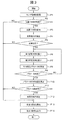
- FIG. 5 is a flow chart showing an example of processing by the control device of the work vehicle of FIG.
- FIG. 3 is a flow chart of a process for detecting steady running in FIG.
- the schematic diagram which shows the relationship between the baseline direction and the vehicle direction between the 1st and 2nd antennas.
- FIG. 3 is a flow chart of a process for calculating the first vehicle direction in FIG.
- FIG. 3 is a flow chart of a process for calculating the second vehicle direction in FIG.
- the schematic diagram which shows an example of the turning included in the steady running.
- the schematic diagram explaining the rotation center of a vehicle.
- the flow chart of the process of calculating the direction correction parameter of FIG. The schematic diagram explaining the direction correction parameter.
- the functional block diagram of the control device in Embodiment 2 of the work vehicle which concerns on this disclosure.
- FIG. 5 is a flow chart showing an example of processing by the steady running detection function of the control device of FIG.
- FIG. 5 is a flow chart showing an example of processing by the traveling control function of the control device of FIG.
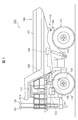
- FIG. 1 is a side view showing the first embodiment of the work vehicle according to the present disclosure.
- FIG. 2 is a functional block diagram of the control device 150 of the work vehicle 100 of FIG.
- the work vehicle 100 of the present embodiment is, for example, a dump truck used at an ore mining site or a construction site.
- the work vehicle 100 includes, for example, a vehicle 110, a positioning device 120, a sensor 130, a vessel 140, and a control device 150.
- the vehicle 110 includes, for example, a body frame 111, wheels 112, and a cabin 113.
- the body frame 111 is, for example, a ladder-shaped structure.
- the body frame 111 supports, for example, the left and right wheels 112 attached to the axle via suspension. Further, the vehicle body frame 111 supports, for example, an engine, a generator, a motor, a power transmission mechanism, a steering mechanism, a hydraulic device, an actuator for vehicle control, and the like (not shown).
- the wheels 112 are connected to a motor via, for example, a power transmission mechanism, and are driven by the motor to drive the vehicle 110.
- the cabin 113 is a passenger compartment for the operator of the work vehicle 100 to board. Inside the cabin 113, for example, a steering wheel (not shown), an operation pedal, an operation lever, an information device, a speaker, an instrument, an indicator lamp, and the like are installed.
- the positioning device 120 can be configured by, for example, a satellite positioning system such as a global positioning satellite system (GNSS).
- the positioning device 120 includes, for example, a first antenna 121, a second antenna 122, and a receiver 123.
- the first antenna 121 and the second antenna 122 are attached to the vehicle 110, for example, and receive radio waves of a satellite positioning system such as GNSS.
- the first antenna 121 and the second antenna 122 are installed apart from each other in the width direction of the vehicle 110, which is orthogonal to the front-rear direction and the height direction of the vehicle 110, for example.
- the first antenna 121 and the second antenna 122 are attached to, for example, the tip of a pole fixed to the vehicle 110, and are installed at a position higher than the steady position of the front end portion 141a of the vessel main body 141.
- the receiver 123 is connected to, for example, the first antenna 121 and the second antenna 122 via a signal cable.
- the receiver 123 outputs the position information of the first antenna 121 and the baseline direction between the first antenna 121 and the second antenna 122 based on the radio waves received by the first antenna 121 and the second antenna 122.
- the baseline direction is, for example, the direction of a straight line connecting the installation position of the first antenna 121 and the installation position of the second antenna 122.
- the sensor 130 includes, for example, a speed sensor 131, an acceleration sensor 132, and an angular velocity sensor 133. Further, in the examples shown in FIGS. 1 and 2, the sensor 130 includes, for example, an elevating sensor 134. These sensors 130 are communicably connected to the control device 150, for example, via a control area network (CAN). When the speed of the vehicle 110 is calculated by the control device 150 based on the position measured by the positioning device 120, the positioning device 120 may be used as the speed sensor and the speed sensor 131 may be omitted.
- CAN control area network
- the speed sensor 131 detects the speed of the vehicle 110 based on, for example, the rotation speed of the wheels 112, and outputs the speed to the control device 150.
- the acceleration sensor 132 detects, for example, the acceleration of the vehicle 110 excluding the gravitational acceleration, and outputs the acceleration to the control device 150.
- the angular velocity sensor 133 detects, for example, the angular velocity of the vehicle 110 and outputs the angular velocity to the control device 150.
- the elevating sensor 134 detects, for example, the elevating state of the vessel main body 141 including the stroke of the elevating cylinder 142 that elevates and elevates the vessel main body 141, and outputs the elevating state to the control device 150.
- the vessel 140 has, for example, a vessel main body 141, an elevating cylinder 142, and a rotating shaft 143.
- the vessel body 141 is rotatably supported on the vehicle body frame 111 around a rotation shaft 143 provided on the rear side of the bottom, for example.
- the vessel main body 141 is a part for loading and transporting a load such as ore, rock, gravel, and earth and sand in the work vehicle 100, for example.
- the elevating cylinder 142 is, for example, a pair of hydraulic cylinders provided on both sides of the vehicle 110 in the width direction.
- the tip of the piston rod is connected to the front of the rotating shaft 143 at the bottom of the vessel body 141, and the end of the cylinder tube on the opposite side of the piston rod is connected to the lower part of the vehicle body frame 111.
- the elevating cylinder 142 constitutes a part of the hydraulic system controlled by the control device 150.
- the elevating cylinder 142 rotates the vessel main body 141 around the rotation shaft 143 by expanding and contracting the piston rod, and raises and lowers the front end portion 141a of the vessel main body 141.
- the control device 150 is, for example, a computer system such as a microcontroller or firmware.
- the control device 150 is composed of, for example, a central processing unit (CPU), a storage device such as a RAM or ROM, a program and data stored in the storage device, a timer, and an input / output unit for inputting / outputting signals. .. Since the control device 150 and the sensor 130 are time-synchronized with each other and operate at a fixed cycle, for example, signal loss due to a time lag is prevented. Further, the drive cycle of the control device 150 can be made equal to, for example, the shortest output cycle of the sensor 130.
- the control device 150 has, for example, a function F100 for calculating the position and posture of the work vehicle 100 and a function F200 for monitoring the state of the work vehicle 100 as shown in FIG. These functions of the control device 150 can be realized, for example, by executing the program stored in the storage device of the control device 150 by the CPU.
- the function F100 for calculating the position and posture of the work vehicle 100 may be abbreviated as the calculation function F100
- the function F200 for monitoring the state of the work vehicle 100 may be abbreviated as the state monitoring function F200.
- the calculation function F100 of the control device 150 includes, for example, a function F101 for storing antenna installation information, a function F102 for storing position and direction information, a function F103 for storing sensor information, and directions. It has a function F108 for storing correction parameters.
- these functions of the control device 150 may be abbreviated as storage functions F101, F102, F103, and F108, respectively.
- the calculation function F100 of the control device 150 further includes a function F104 for calculating the first vehicle direction, a function F105 for calculating the second vehicle direction, and a function F106 for detecting steady running. , Has a function F107 for calculating the direction correction parameter.
- these functions of the control device 150 may be abbreviated as calculation functions F104 and F105, detection function F106, and calculation function F107, respectively.
- the calculation function F100 of the control device 150 further has a function F109 for determining whether or not the direction correction parameter can be used, and a function F110 for estimating the position and posture of the work vehicle 100.
- these functions of the control device 150 may be abbreviated as a determination function F109 and an estimation function F110, respectively.
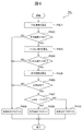
- FIG. 3 is a flow chart showing an example of processing by the control device 150 of the work vehicle 100 of FIG.
- the control device 150 executes the process shown in FIG. 3 by, for example, the calculation function F100.
- the storage function F103 executes the process P1 for storing the sensor information.
- the storage function F103 stores the sensor information input from the sensor 130 via the input / output unit of the control device 150 in the storage device constituting the control device 150.
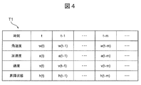
- FIG. 4 is a table T1 showing an example of sensor information stored by the storage function F103 in the process P1.
- the sensor information includes, for example, a velocity v, an acceleration a, an angular velocity w, and an ascending / descending state h, which are output values from each of the velocity sensor 131, the acceleration sensor 132, the angular velocity sensor 133, and the elevating sensor 134 included in the sensor 130. ..
- the sensor information includes, for example, the time t, t-1, ..., Tm, ... When each output value is output.
- the storage device of the control device 150 includes, for example, sensor information at the current time t and sensor information at times t-1, ..., Tm, ... Before the current time t, and sensor information for a certain period of time. I remember.
- the position information of the first antenna 121 and the baseline direction connecting the first antenna 121 and the second antenna 122 are from the receiver 123.
- the period is longer than the output cycle.
- the speed, acceleration, and angular velocity included in the sensor information may be the output values of the speed sensor 131, the acceleration sensor 132, and the angular velocity sensor 133, and the output values of each sensor are converted into three-dimensional notation in vehicle coordinates. It may be the value obtained.
- the control device 150 determines whether, for example, the position information of the first antenna 121 and the baseline direction connecting the first antenna 121 and the second antenna 122 are both acquired from the receiver 123.
- Process P2 is executed.
- the position information of the first antenna 121 is the position information of the first antenna 121 that is output from the receiver 123 as a result of the signal being input from the first antenna 121 that has received the GNSS radio wave to the receiver 123. ..
- the baseline direction for example, signals are input from the first antenna 121 and the first antenna 121 that have received the GNSS radio wave to the receiver 123, and as a result, the first antenna 121 and the second antenna are output from the receiver 123. This is the direction of the straight line connecting the antenna 122.
- the storage function F102 of the control device 150 acquires, for example, the position information of the first antenna 121 and the baseline direction from the receiver 123 at regular intervals and stores them in the storage device of the control device 150. .. Therefore, in the process P2, for example, whether or not the position information of the first antenna 121 and the baseline direction connecting the first antenna 121 and the second antenna 122 are both acquired from the receiver 123 in the control device 150. To judge.
- the position information of the first antenna 121 is output from the receiver 123 in a cycle of 1 [Hz], and the baseline direction connecting the first antenna 121 and the second antenna 122 is 10 [Hz]. It is assumed that the output is periodic.
- the control device 150 determines in the process P2 that the position information of the first antenna 121 was not acquired (NO) at the time when only the baseline direction was acquired from the receiver 123, and the process P13 described later. To execute.
- the control device 150 determines in the process P2 that both the position information of the first antenna 121 and the baseline direction are acquired (YES)
- the control device 150 executes the next process P3.
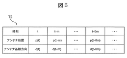
- FIG. 5 is a table T2 showing an example of the position information p and the baseline direction d of the first antenna 121 stored in the storage device of the control device 150 in the process P3.
- the control device 150 obtains the position information p of the first antenna 121 acquired from the receiver 123 and the baseline direction d by the storage function F102 at the acquired times t, tm, ..., T-. It is stored in the storage device together with 6 m, ....
- FIG. 5 shows an example in which the position information p of the first antenna 121 and the baseline direction d are output together for each period m.
- the position information p of the first antenna 121 is, for example, information indicating a point on a map, and is two-dimensional or three-dimensional position information.
- the baseline direction d connecting the first antenna 121 and the second antenna 122 is, for example, a two-dimensional or three-dimensional vector or an orientation.
- the control device 150 executes the next process P4.
- FIG. 6 is a flow chart of the process P4 for detecting the steady running of FIG.
- Each process shown in FIG. 6 can be executed by, for example, the detection function F106 of the control device 150.
- the control device 150 starts the process P4, the control device 150 first executes the process P401 for calculating the average speed.
- the control device 150 refers to, for example, the storage device, and refers to the time when the position information p of the first antenna 121 one cycle before is acquired from the positioning device 120.
- the control device 150 calculates the average speed of the vehicle 110 by using, for example, the speed v of the vehicle 110 from the time when the position information p of the first antenna 121 one cycle ago was acquired to the present.
- the control device 150 executes the process P402 for determining whether or not the calculated average speed of the vehicle 110 is higher than the predetermined speed threshold value Vth.
- the control device 150 determines that the calculated average speed of the vehicle 110 is equal to or less than a predetermined speed threshold value Vth (NO)
- the control device 150 executes the next process P408.
- the control device 150 sets the steady running flag stored in the storage device to 0, and ends the process shown in FIG.
- the state in which the steady-state running flag is 0 indicates that the work vehicle 100 is not in steady-state running. That is, the steady running includes that the average value of the speeds of the vehicles 110 is higher than the predetermined speed threshold value Vth. As a result, while the vehicle 110 is stopped and low-speed traveling below the speed threshold value Vth is excluded from steady traveling.
- the control device 150 determines, for example, that the calculated average speed of the vehicle 110 is higher than the predetermined speed threshold value Vth (YES)
- the control device 150 executes the next process P403.
- the control device 150 calculates, for example, the height of the vessel 140.
- the control device 150 refers to, for example, a storage device, and the height of the vessel 140 is based on the current time and the ascending / descending state of the vessel 140 at the time when the output of the positioning device 120 one cycle before is acquired. Calculate the time.
- the height of the vessel 140 is, for example, the height of the front end portion 141a of the vessel main body 141.
- the control device 150 can obtain the height of the front end portion 141a of the vessel main body 141 by using, for example, the sine of the angle of the vessel main body 141.
- the dimensional data of the vessel main body 141 is stored in advance in the storage device of the control device 150, for example. After the end of the process P403, the control device 150 executes the next process P404.
- the control device 150 determines, for example, whether or not the height of the vessel 140 calculated in the process P403 is lower than the predetermined height threshold value Hth. More specifically, in the control device 150, for example, whether or not the height of each vessel 140 at the current time and the time when the position information p is acquired from the previous positioning device 120 is lower than the height threshold value Hth. Is determined.
- the height threshold value Hth is set to, for example, a height equal to the height of the first antenna 121 or the second antenna 122, or a lower height of the first antenna 121 and the second antenna 122. be able to.
- the control device 150 has, for example, the current time and the time when the position information p is acquired from the previous positioning device 120, or one of the heights of the vessel 140 is equal to or higher than the height threshold value Hth (). It is assumed that it is determined as NO). In this case, the control device 150 executes the process P408 for setting the steady running flag to 0, and ends the process P4 shown in FIG.
- the height of the vessel 140 is lower than the height threshold value Hth of the control device 150, for example, at both or one of the current time and the time when the position information p is acquired from the previous positioning device 120. It is assumed that (YES) is determined.
- the control device 150 executes, for example, the process P405 for calculating the traveling state of the work vehicle 100. More specifically, in the process P405, the control device 150 calculates the average values of the angular velocity, the angular acceleration, and the acceleration of the work vehicle 100 and the change in the direction of the vehicle 110.
- the average values of the angular velocity, the angular acceleration, and the acceleration of the work vehicle 100 are, for example, the average values from the time when the position information p was acquired from the previous positioning device 120 to the current time.
- the angular acceleration of the work vehicle 100 can be calculated, for example, from the difference between the angular velocity of the work vehicle 100 at a certain time and the angular velocity of the work vehicle 100 at the time one cycle before the angular velocity.
- the direction of the vehicle 110 that is, the change in the vehicle direction can be calculated as follows, for example.
- FIG. 7 is a schematic diagram showing the relationship between the baseline direction d connecting the first antenna 121 and the first antenna 121 and the vehicle direction Dv.
- the work vehicle 100 has an angle ⁇ along the circumference of the vehicle 110 centered on the center Ct between the time when the position information p was acquired from the previous positioning device 120 and the current time. Only turning and moving.
- the vehicle direction Dv changes at an angle equal to the angle ⁇ at which the vehicle 110 turns.
- the baseline direction d that is, the baseline vector, also changes at an angle equal to the angle ⁇ at which the vehicle 110 turns.
- the angle change of the vehicle direction Dv can be calculated by calculating the angle change of the baseline direction d between the current time and the time when the position information p is acquired from the previous positioning device 120. That is, in the process P405, the control device 150 calculates the angle change in the vehicle direction Dv by, for example, calculating the angle change in the baseline direction d. As described above, in the process P405, the control device 150 calculates, for example, the average values of the angular velocity, the angular acceleration, and the acceleration of the work vehicle 100, and the angular change of the vehicle direction Dv.
- the control device 150 executes, for example, the process P406 for determining whether or not the traveling state of the work vehicle 100 is steady traveling.
- the steady running is, for example, a state in which the work vehicle 100 is running in a constant motion state. More specifically, the steady running of the work vehicle 100 includes, for example, turning in which the work vehicle 100 travels along a circumference having the same center and radius, and straight travel in which the work vehicle 100 travels in a straight line.
- the steady running is not limited to turning and going straight, and may include other running states.
- the control device 150 is centered on the work vehicle 100 when, for example, the difference between the change in the vehicle direction Dv calculated in the previous process P405 and the time-minute integration of the angular velocity of the vehicle 110 is equal to or less than the threshold value. It is determined that the vehicle is turning along the same circumference. In this case, since the turning of the work vehicle 100 is included in the steady running, the control device 150 determines in the process P406 that the running state of the work vehicle 100 is the steady running (YES), and executes the next process P407. do.
- the control device 150 is traveling straight in which the work vehicle 100 travels in a straight line when, for example, the average value of the angular acceleration and the acceleration of the vehicle 110 calculated in the previous process P405 is equal to or less than the threshold value. Is determined. In this case, since the straight running of the work vehicle 100 is included in the steady running, the control device 150 determines in the process P406 that the running state of the work vehicle 100 is the steady running (YES), and executes the next process P407. do.
- the control device 150 determines that the running state of the work vehicle 100 is not steady running (NO), executes the process P408 for setting the above-mentioned steady running flag to 0, and is shown in FIG. The process P4 shown is terminated.
- the control device 150 determines whether or not the absolute value
- the control device 150 executes the process P409 for setting the steady running flag stored in the storage device to 1. , The process P4 shown in FIG. 6 is terminated.
- the state in which the steady running flag is 1 indicates that the running state of the work vehicle 100 is traveling straight.
- the control device 150 determines that the absolute value
- the control device 150 executes the process P410 for setting the steady running flag stored in the storage device to 2.
- the process P4 shown in FIG. 6 is terminated.
- the state where the steady running flag is 2 indicates that the running state of the work vehicle 100 is a turn that runs along a circumference having the same center and radius.
- the control device 150 executes the process P5 shown in FIG.
- the control device 150 determines, for example, whether or not the traveling state of the work vehicle 100 is steady traveling by the detection function F106. Specifically, the control device 150 refers to the steady-state traveling flag set in the previous process P4 and stored in the storage device by the detection function F106. When the referenced steady-state travel flag is 0, it indicates that the work vehicle 100 is not in steady-state travel. Therefore, the control device 150 determines that the work vehicle 100 is not in steady-state travel (NO) by the detection function F106, and determines that the position is not steady-state. And the process P13 for estimating the posture is executed.
- the control device 150 uses the direction correction parameter stored in the storage device through the previous processes P6 to P12 in the process P13.
- the position and posture of the work vehicle 100 are estimated.
- the process P13 for estimating the position and posture of the work vehicle 100 will be described in detail below after the processes P6 to P12 are described.
- the process P5 when the referenced steady-state running flag is 1 or 2, it indicates that the work vehicle 100 is in steady-state running, so that the control device 150 is in steady-state running by the detection function F106 (YES). ), And the process P6 for calculating the first vehicle direction is executed.
- the first vehicle direction is the direction of the vehicle 110 calculated based on the installation information of the first antenna 121 and the second antenna 122.
- This installation information includes, for example, the coordinates of the positions where the first antenna 121 and the second antenna 122 are installed, and is stored in the storage device of the control device 150 by the storage function F101 of the control device 150 shown in FIG. ..
- FIG. 8 is a flow chart of the process P6 for calculating the first vehicle direction.
- the control device 150 starts the process P6 for calculating the first vehicle direction
- the control device 150 first executes the process P601 for acquiring the direction correction parameter by the calculation function F104.
- the control device 150 acquires, for example, the latest direction correction parameter stored in the storage device by the storage function F101 by the calculation function F104.
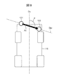
- FIG. 9 is a schematic diagram illustrating the direction correction parameters acquired in the process P601 shown in FIG.
- the first antenna 121 and the second antenna 122 are installed in the vehicle 110 and their positions are fixed. Based on the installation position of the first antenna 121 and the installation position of the second antenna 122 with respect to the vehicle 110, the vector Av from the first antenna 121 to the second antenna 122 can be obtained. Further, the direction of the center line of the vehicle 110 parallel to the front-rear direction of the vehicle 110 is defined as the vehicle direction Dv.
- the installation information of the first antenna 121 and the second antenna 122 includes the antenna installation angle ⁇ , which is the angle formed by the vehicle direction Dv and the vector Av.
- the direction correction parameter is a parameter for correcting the change when the antenna installation angle ⁇ changes for some reason.
- the antenna installation angle ⁇ and the direction correction parameter are calculated in the same manner even if the installation positions of the first antenna 121 and the second antenna 122 are represented by the coordinates of the coordinate system fixed to the vehicle 110, for example, by performing coordinate conversion. It is possible.
- the direction correction parameter is calculated by the calculation function F107 of the control device 150 and stored in the storage device by the storage function F108 in the process P8 described later.
- the direction correction parameters for a certain period of time are stored together with the time.
- 0 as an initial value is stored in the storage device of the control device 150.
- the antenna installation angle ⁇ is not corrected.
- the control device 150 executes the process P602 for calculating the first vehicle direction by, for example, the calculation function F104. Specifically, for example, the control device 150 uses the calculation function F104 to set the vehicle direction Dv by using the value obtained by subtracting the direction correction parameter from the antenna installation angle ⁇ shown in FIG. 9 and the vector Av shown in FIG. The calculation is performed, and the process P6 shown in FIG. 8 is terminated.
- the vehicle direction Dv calculated by this process P6 is the first vehicle direction derived from the installation positions of the first antenna 121 and the second antenna 122.
- the control device 150 executes the process P7 for calculating the second vehicle direction by, for example, the calculation function F105, as shown in FIG.
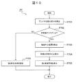
- FIG. 10 is a flow chart of the process P7 for calculating the second vehicle direction. Each process shown in FIG. 10 is executed by, for example, the calculation function F105 of the control device 150.
- the control device 150 first executes the process P701 for calculating the difference between the antenna positions.
- the control device 150 acquires the position information p of the first antenna 121 that is input from the receiver 123 of the positioning device 120 to the control device 150 and stored in the storage device by the storage function F102 of the control device 150.
- the control device 150 acquires the current position information p of the first antenna 121 and the position information p of the first antenna 121 one cycle before.
- the control device 150 calculates the moving direction of the vehicle 110 based on the difference between the current position information p of the first antenna 121 and the position information p of the first antenna 121 one cycle before. do. More specifically, the control device 150 calculates the movement vector of the vehicle 110 based on the difference between the current position information p of the first antenna 121 and the position information p of the first antenna 121 one cycle before.
- the control device 150 executes the process P702 for determining whether or not the steady running flag is 2. It is assumed that in the process P702, the control device 150 determines that the steady-state running flag is not 2 (NO), that is, the steady-state running flag is 1. In this case, the traveling state of the vehicle 110 is a straight-ahead traveling in a straight line, and the vehicle direction Dv and the traveling direction of the vehicle 110 coincide with each other. Therefore, the control device 150 executes the process P706 for setting the movement vector of the vehicle 110 calculated in the previous process P701 as the second vehicle direction, and ends the process P7 shown in FIG.
- the control device 150 determines that the steady running flag is 2 (YES). In this case, the traveling state of the vehicle 110 is a turn traveling along a circle having the same center and radius. Therefore, the control device 150 executes the process P703 for calculating the position of the center of turning of the vehicle 110.
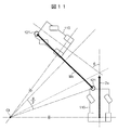
- FIG. 11 is a schematic view showing an example of turning included in the steady running of the work vehicle 100.
- FIG. 11 shows the position of the vehicle 110 that turns counterclockwise around the center Ct at the current time and the position at the time one cycle before.
- the control device 150 first determines the vehicle at the time one cycle before, based on the position information p of the first antenna 121 at the time one cycle before and the position information p of the first antenna 121 at the current time.
- the vehicle direction Dv of 110 is calculated.
- the vehicle 110 is turning along a circle having the same center Ct and radius. Therefore, the rotation angle of the vehicle 110 around the center Ct between the time one cycle before and the current time is equal to the angle ⁇ between the vehicle direction Dv at the time one cycle before and the vehicle direction Dv at the current time. ..
- the center Ct of the turn of the vehicle 110 is on the bisector of the movement vector Mv calculated by the above-mentioned process P701. Further, the distance D from the movement vector Mv to the center Ct of the turn can be obtained by the following equation (1), where L is the length of the movement vector Mv.
- the control device 150 can calculate the center Ct of the turn by, for example, calculating the normal with respect to the movement vector Mv from the average of the angular velocities of the vehicle 110.
- the control device 150 executes the process P704 for calculating the rotation center of the vehicle 110.
- the control device 150 first calculates a vector from the position of the first antenna 121 toward the rotation center of the vehicle 110. Therefore, the control device 150 calculates a vector from the installation position of the first antenna 121 to the installation position of the acceleration sensor 132 and a vector from the installation position of the acceleration sensor 132 toward the rotation center of the vehicle 110.
- FIG. 12 is a schematic view illustrating the rotation center Ctv of the vehicle 110.
- the rotation center Ctv of the vehicle 110 is a point where the vehicle 110 is regarded as one rigid body and the direction of the speed vector Vv of the vehicle 110 and the vehicle direction Dv are equal to each other.
- the direction of the speed vector Vv of the vehicle 110 is the normal direction of the line segment connecting the center Ct of the turning of the vehicle 110 and the center Ctv of the rotation of the vehicle 110.
- the vector from the installation position of the acceleration sensor 132 toward the rotation center Ctv of the vehicle 110 can be calculated as follows.
- the ax which is a component in the front-rear direction of the vehicle 110, is extracted from the average value of the acceleration of the vehicle 110 calculated in the above-mentioned process P4. Further, the average value wz of the angular velocity in the yaw direction and the deviation g from the vehicle direction Dv are used. As a result, the vector from the installation position of the acceleration sensor 132 toward the rotation center Ctv of the vehicle 110 can be obtained as (ax / (wz ⁇ wz), g).
- a vector from the first antenna 121 toward the acceleration sensor 132 and a vector from the acceleration sensor 132 toward the rotation center Ctv of the vehicle 110 are obtained. Further, by adding these vectors, it is possible to obtain a vector from the first antenna 121 toward the rotation center Ctv of the vehicle 110.
- the rear wheel axle center Cra can be defined as the rotation center of the vehicle 110 according to the Ackermann geometry.
- the vector from the first antenna 121 to the rear wheel axle center Cra can be calculated in advance based on the specifications of the vehicle 110 and stored in the storage device of the control device 150.
- the control device 150 uses the vector from the first antenna 121 toward the rotation center Ctv of the vehicle 110 and the vector in the baseline direction connecting the first antenna 121 and the second antenna 122 to the vehicle 110.
- the rotation center Ctv of is calculated. Specifically, the vector from the first antenna 121 toward the rotation center Ctv of the vehicle body frame 111 is rotated around the position of the first antenna 121 one cycle before stored in the storage device of the control device 150 by the storage function F102. Let me.
- the amount of rotation of the vector at this time is determined, for example, by calculating the direction of the first vehicle.
- the first vehicle direction is, for example, the value obtained by subtracting the direction correction parameter from the antenna installation angle ⁇ shown in FIG. 9 and the first antenna 121 to the second antenna 122 one cycle before, as in the above-described processing P602. It can be obtained by using the vector Av toward. From the above, the control device 150 can calculate the rotation center Ctv of the vehicle 110 in the process P704.
- control device 150 executes the process P705 for calculating the second vehicle direction.
- the control device 150 calculates the second vehicle direction based on the turning center Ct of the vehicle 110 calculated in the above process P703 and the rotation center Ctv of the vehicle 110 calculated in the above process P704. Then, the process P7 shown in FIG. 10 is terminated.
- the second vehicle direction calculated by this process P7 is the vehicle direction derived from the information output from the positioning device 120 receiver 123.
- the second vehicle direction can be calculated as the normal direction obtained by the right-handed system with respect to the vector from the turning center Ct of the vehicle 110 to the rotation center Ctv of the vehicle 110.
- the control device 150 executes the process P8 for calculating the direction correction parameter shown in FIG.
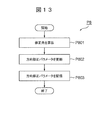
- FIG. 13 is a flow chart of the process P8 for calculating the direction correction parameter.
- FIG. 14 is a schematic diagram illustrating the process P8.
- the correction angle ⁇ is, for example, the angle formed by the first vehicle direction Dv1 and the second vehicle direction Dv2.
- the first vehicle direction Dv1 is the vehicle direction derived from the installation positions of the first antenna 121 and the second antenna 122
- the second vehicle direction Dv2 is the first output from the receiver 123 of the positioning device 120. This is the vehicle direction derived from the position information p of the antenna 121.
- the control device 150 calculates the difference between the first vehicle direction Dv1 and the second vehicle direction Dv2 by the calculation function F107, and the first vehicle direction Dv1. Is calculated to be equal to the second vehicle direction Dv2.
- the control device 150 executes the process P802 for updating the direction correction parameter.
- the control device 150 updates the direction correction parameter by adding the correction angle ⁇ calculated in the previous process P801 to the direction correction parameter stored in the storage device by the calculation function F107. do.
- the control device 150 executes the process P803 for storing the direction correction parameter.
- the control device 150 stores the direction correction parameter updated in the previous process P802 in the storage device by the storage function F108, and ends the process P8 shown in FIG.
- the control device 150 executes, for example, the process P9 for determining whether or not the direction correction parameters have converged, as shown in FIG. 3, by the determination function F109.
- the second vehicle direction Dv2 is also used in the process P704 for calculating the rotation center Ctv of the vehicle 110 shown in FIG. Therefore, the second vehicle direction Dv2 also has an error that cannot be completely removed by the previous direction correction parameter.
- the control device 150 performs the convergence calculation in the process P9 by performing the calculation again using the latest direction correction parameters calculated in the previous process P8.
- the control device 150 determines that the direction correction parameters have converged (YES), for example, when the absolute value of the correction angle ⁇ calculated in the process P801 shown in FIG. 13 is smaller than the preset threshold value. Then, the next process P10 is executed. On the other hand, in the process P9, when the absolute value of the correction angle ⁇ is, for example, equal to or greater than a preset threshold value, the control device 150 determines that the direction correction parameters have not converged (NO), and processes from the process P6. Repeat up to P9.
- the control device 150 executes the process P10 for calculating the average value of the direction correction parameters by, for example, the determination function F109.
- the direction correction parameter is calculated based on the position information p of the first antenna 121 input from the receiver 123 of the positioning device 120 to the control device 150 for each sampling cycle. Therefore, an error also occurs in the direction correction parameter due to the position error that occurs when the receiver 123 performs the positioning calculation based on the GNSS radio wave received by the first antenna 121.
- the control device 150 executes the sequential averaging of the direction correction parameter in the process P10.
- the sequential averaging of the direction correction parameters for example, an upper limit of the number of integrations may be set or an oblivion coefficient may be introduced to suppress an excessive increase in the number of integrations. As a result, it is possible to prevent the change in the direction correction parameter from being reflected.
- the control device 150 executes, for example, the process P11 for determining whether or not the direction correction parameter can be used by the determination function F109.
- the direction correction parameters calculated at each time include an error, the average value of the direction correction parameters calculated in a predetermined period is calculated. Therefore, it is necessary that a certain number or more of the direction correction parameters are calculated and that the fluctuation of the direction correction parameters for each cycle is not excessive.
- the control device 150 executes the process P12 for correcting the vehicle direction using the direction correction parameter, and the process P13 for estimating the position and attitude of the vehicle 110 by the estimation function F110 based on the corrected vehicle direction. Run.
- the control device 150 determines that the direction correction parameter cannot be used (NO)
- the control device 150 executes the process P13 for estimating the position and attitude of the vehicle 110 by the estimation function F110 without using the direction correction parameter. do.
- the control device 150 outputs the average value of the direction correction parameters calculated in the process P10 and the position and attitude of the vehicle 110 estimated in the process P13 to the state monitoring function F200 via CAN in the process P14. Run. As a result, each process shown in FIG. 3 by the calculation function F100 of the control device 150 is completed.
- condition monitoring function F200 of the control device 150 has an error in the installation position of the first antenna 121 or the second antenna 122 based on the installation information of the first antenna 121 and the second antenna 122 and the direction correction parameter. Detect what is happening. Further, the condition monitoring function F200 of the control device 150 determines, for example, an abnormality in the installation positions of the first antenna 121 and the second antenna 122 when the direction correction parameter exceeds a predetermined threshold value.
- the work vehicle 100 may be provided with an information notification device for notifying the operator or the user of the information.
- an information notification device for example, a liquid crystal display device, an indicator lamp, a speaker, a buzzer, or the like can be used.
- the condition monitoring function F200 of the control device 150 outputs error information with respect to the installation information of the first antenna 121 and the second antenna 122 to the information notification device when the direction correction parameter exceeds a predetermined threshold value.
- the operator or user of the work vehicle 100 can be notified of the abnormality.
- the work vehicle 100 of the present embodiment includes a vehicle 110 and a first antenna 121 and a second antenna 122 that are attached to the vehicle 110 and receive radio waves of the satellite positioning system. Further, the work vehicle 100 includes a receiver 123 that outputs the position information p of the first antenna 121 based on the radio waves of the satellite positioning system and the baseline direction d between the first antenna 121 and the second antenna 122. There is. Further, the work vehicle 100 includes a sensor 130 for measuring the speed, acceleration, and angular velocity of the vehicle 110, and a control device 150 for estimating the position and posture of the vehicle 110.
- the control device 150 has a detection function F106, a calculation function F104, a calculation function F105, a calculation function F107, and an estimation function F110.
- the detection function F106 is a function of detecting steady running based on the speed, acceleration, and angular velocity of the vehicle 110.
- the calculation function F104 is a function of calculating the first vehicle direction Dv1 based on the installation information of the first antenna 121 and the second antenna 122 with respect to the vehicle 110.
- the calculation function F105 is a function of calculating the second vehicle direction Dv2 based on the time change of the position information p of the first antenna 121 when steady running is detected.
- the calculation function F107 is a function of calculating a direction correction parameter for correcting the first vehicle direction Dv1 based on the second vehicle direction Dv2.
- the estimation function F110 is a function of estimating the position and attitude of the vehicle 110 based on the direction correction parameter and the first vehicle direction Dv1.
- the work vehicle 100 of the present embodiment it is possible to detect an error in the installation positions of the first antenna 121 and the second antenna 122 more flexibly than the conventional device. More specifically, the first antenna 121 and the second antenna 122 are attached to, for example, the tips of poles extending upward from the vehicle body frame 111 so that radio waves from the satellite positioning system are not blocked by the vehicle 110, vessel 140, or the like. .. Further, the work vehicle 100, for example, loads ore, earth and sand, etc. on the vessel 140, unloads the load from the vessel 140, and travels on uneven ground such as a mine or a construction site. Therefore, vibration or impact may act on the first antenna 121 and the second antenna 122.
- an error may occur between the preset installation positions of the first antenna 121 and the second antenna 122 and the actual installation positions.
- an error may occur between the first vehicle direction Dv1 calculated based on the preset installation position and the actual vehicle direction.
- the work vehicle 100 of the present embodiment has a first antenna based on the radio waves of the satellite positioning system received by the first antenna 121 when steady running is detected by the detection function F106 of the control device 150.
- the second vehicle direction Dv2 is calculated using the time change of the position information p of 121.
- a direction correction parameter for correcting the first vehicle direction Dv1 is calculated based on the second vehicle direction Dv2, and the position and attitude of the vehicle 110 are estimated based on the direction correction parameter and the first vehicle direction Dv1. That is, the work vehicle 100 of the present embodiment has a first vehicle direction Dv1 and an actual vehicle by performing steady running including not only extremely limited running states as in the conventional device but also more various running states.
- the error between the direction Dv and the direction Dv can be corrected more flexibly. Further, the work for detecting the error generated at the installation position of the first antenna 121 and the second antenna 122 becomes unnecessary.
- the control device 150 further has a determination function F109 for determining whether or not the direction correction parameter can be used. Then, the estimation function F110 of the control device 150 estimates the position and attitude of the vehicle 110 based on the direction correction parameter and the first vehicle direction Dv1 when the direction correction parameter is available. With this configuration, for example, it is possible to prevent the first vehicle direction Dv1 from being corrected based on the direction correction parameter including a large error, and it is possible to correct the first vehicle direction Dv1 more accurately.
- the steady traveling includes a turning traveling along a circumference having the same center and a radius, and a straight traveling traveling in a straight line.
- the steady running includes that the average value of the speeds of the vehicles 110 is higher than the predetermined speed threshold value Vth.
- the work vehicle 100 of the present embodiment includes a vessel 140 attached to the vehicle 110, an elevating cylinder 142 which is an elevating mechanism for elevating and elevating the vessel 140, and an elevating sensor 134 for detecting the height of the vessel 140. ing. Then, in the work vehicle 100 of the present embodiment, the steady running includes that the height of the vessel 140 is lower than the predetermined height threshold value Hth.
- the work vehicle 100 of the present embodiment is the second vehicle when, for example, the front end portion 141a of the vessel main body 141 is equal to or higher than the height threshold value Hth based on the heights of the first antenna 121 and the second antenna 122.
- Direction Dv2 is not calculated. Therefore, it is possible to prevent the calculation of the second vehicle direction Dv2 in a state where the radio wave from the satellite positioning system to the first antenna 121 or the second antenna 122 is blocked by the vessel 140, and the error of the second vehicle direction Dv2 is reduced. .. Therefore, according to the work vehicle 100 of the present embodiment, the position and posture of the vehicle 110 can be estimated more accurately.
- the work vehicle 100 of the present embodiment can be provided with an information notification device for notifying an operator or a user of information.
- the control device 150 can output error information with respect to the installation information of the first antenna 121 and the second antenna 122 to the information notification device when the direction correction parameter exceeds a predetermined threshold value.
- the work vehicle 100 of the present embodiment can notify the operator or the user that an error in the installation position of the first antenna 121 or the second antenna 122 has occurred.
- the work vehicle 100 capable of detecting an error in the installation position of the first antenna 121 or the second antenna 122 more flexibly than the conventional device. ..
- FIG. 15 is a functional block diagram of the control device 150 showing the second embodiment of the work vehicle according to the present disclosure.
- the function of the work vehicle 100 of the present embodiment is different from that of the work vehicle 100 of the above-described first embodiment in the function provided by the control device 150. Since the other points of the work vehicle 100 of the present embodiment are the same as those of the work vehicle 100 of the first embodiment, the same reference numerals are given to the same parts and the description thereof will be omitted.
- the control device 150 has a position and posture calculation function F100'similar to the calculation function F100 of the first embodiment described above. Further, in the work vehicle 100 of the present embodiment, the control device 150 has a travel control function F300 instead of the condition monitoring function F200. In the control device 150 of the present embodiment, the calculation function F100'outputs the estimation result of the position and posture of the vehicle 110 by the estimation function F110 and the detection result of steady running by the detection function F106 to the travel control function F300.
- the travel control function F300 executes the travel control of the vehicle 110 based on the estimation result and the detection result input from the calculation function F100'. More specifically, the travel control function F300 controls various actuators of the vehicle 110 to automatically operate the accelerator pedal, brake pedal, transmission, steering wheel, etc. of the vehicle 110 to drive the vehicle 110. Let me. Further, in the work vehicle 100 of the present embodiment, for example, the control device 150 detects the steady running shown in FIG. 16 by the detection function F106 instead of the process P4 for detecting the steady running shown in FIGS. 3 and 4. Process P4'is executed.
- FIG. 16 is a flow chart showing an example of processing P4'by the detection function F106 of the control device 150 of the present embodiment.
- the same processes as the process P4 of the first embodiment shown in FIG. 6 are designated by the same reference numerals, and the description thereof will be omitted.
- the detection function F106 stores the unsteady state in the storage device.
- the process P412 for setting the flag to 1 is executed.
- the state in which the non-steady flag is set to 1 indicates that the traveling state of the vehicle 110 is not steady traveling and the direction correction parameter cannot be calculated.
- the control device 150 executes the process P408 for setting the steady running flag to 0, as in the first embodiment.
- the initial values of the speed shortage flag and the non-stationary flag are 0, and they are initialized at the same time when the control device 150 is started for each sampling cycle.
- the control device 150 of the present embodiment executes the traveling control of the vehicle 110 by the traveling control function F300 so that the traveling state of the vehicle 110 becomes a steady traveling state.
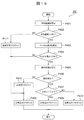
- FIG. 17 is a flow chart showing an example of processing P15 by the traveling control function F300 of the control device 150 in the work vehicle 100 of the present embodiment.
- the control device 150 starts the process P15 shown in FIG. 17, the control device 150 first executes the process P1501 for acquiring the speed shortage flag and the unsteady flag stored in the storage device.
- the control device 150 executes the process P1502 for determining whether or not the speed shortage flag is 1.
- the control device 150 determines that the speed shortage flag is 1 (YES)
- the control device 150 executes the process P1503 for setting the driving control parameters for accelerating the vehicle 110 to a predetermined speed exceeding the speed threshold value Vth.
- the control device 150 executes the process P1509 for determining the presence / absence of an interrupt, which will be described later.
- the control device 150 determines that the speed shortage flag is not 1 (NO)
- the control device 150 executes the process P1504 for determining whether or not the non-stationary flag is 1.
- the control device 150 determines that the non-stationary flag is not 1 (NO)
- it can determine that the traveling state of the vehicle 110 is steady traveling in which the direction correction parameter can be calculated.
- the process P1509 for determining the presence / absence is executed.
- the control device 150 determines that the unsteady flag is 1 (YES)
- the control device 150 executes the process P1505 for determining whether or not the speed of the vehicle 110 is higher than the predetermined speed threshold value Vth'. ..
- the control device 150 decelerates the vehicle 110 so that the speed of the vehicle 110 falls within the speed range of steady running.
- the process P1506 for setting the control parameters is executed. After the end of this process P1506, the control device 150 executes the process P1509 for determining the presence / absence of an interrupt, which will be described later.
- the control device 150 determines that the speed of the vehicle 110 is equal to or less than the predetermined speed threshold value Vth'(NO), it can be determined that the speed of the vehicle 110 cannot be adjusted.
- the control device 150 executes the process P1507 for determining whether or not the absolute value
- the control device 150 determines that the absolute value
- control device 150 executes the process P1508 for setting the travel control parameters for maintaining the steering angle of the steering wheel. After the end of this process P1508, the control device 150 executes the process P1509 for determining the presence / absence of an interrupt, which will be described later.
- the control device 150 determines that the absolute value
- the control device 150 executes the process P1509 for determining the presence / absence of an interrupt.
- the control device 150 determines whether or not an interrupt signal for stopping control is input from another control device and whether or not there is an interrupt for the operation of the vehicle 110 by the operator of the vehicle 110.
- the control device 150 determines that there is no interrupt (NO)
- the control device 150 executes the process P1510 that controls the traveling of the vehicle 110 based on the parameters set in the above-mentioned processes P1503, P1506, or P1508.
- the process P15 shown in FIG. 17 is terminated.
- the control device 150 determines that there is an interrupt (YES)
- the control device 150 executes the process P1511 for stopping the travel control of the vehicle 110 based on the parameters set in the above-mentioned processes P1503, P1506, or P1508.
- the process P15 shown in FIG. 17 is terminated.
- the control device 150 has a travel control function F300 that controls the travel of the vehicle 110.
- the travel control function F300 controls the vehicle 110 so as to satisfy the steady travel condition when the detection function F106 does not detect the steady travel of the vehicle 110.
Landscapes
- Engineering & Computer Science (AREA)
- Radar, Positioning & Navigation (AREA)
- Remote Sensing (AREA)
- Physics & Mathematics (AREA)
- General Physics & Mathematics (AREA)
- Aviation & Aerospace Engineering (AREA)
- Automation & Control Theory (AREA)
- Computer Networks & Wireless Communication (AREA)
- Position Fixing By Use Of Radio Waves (AREA)
- Control Of Position, Course, Altitude, Or Attitude Of Moving Bodies (AREA)
Abstract
Description
図1は、本開示に係る作業車両の実施形態1を示す側面図である。図2は、図1の作業車両100の制御装置150の機能ブロック図である。本実施形態の作業車両100は、たとえば、鉱石の採掘現場や建設現場で使用されるダンプトラックである。作業車両100は、たとえば、車両110と、測位装置120と、センサ130と、ベッセル140と、制御装置150とを備えている。
以下、実施形態1で用いた一部の図を援用し、さらに図15から図17を参照して、本開示に係る作業車両の実施形態2を説明する。図15は、本開示に係る作業車両の実施形態2を示す制御装置150の機能ブロック図である。本実施形態の作業車両100は、制御装置150が備える機能が、前述の実施形態1の作業車両100と異なっている。本実施形態の作業車両100のその他の点は、前述の実施形態1の作業車両100と同様であるため、同様の部分には同一の符号を付して説明を省略する。
110 車両
121 第1アンテナ
122 第2アンテナ
123 受信機
130 センサ
134 昇降センサ
140 ベッセル
142 昇降シリンダ(昇降機構)
150 制御装置
Ct 中心
d 基線方向
Dv1 第1車両方向
Dv2 第2車両方向
F104 第1車両方向を算出する機能
F105 第2車両方向を算出する機能
F106 検出機能
F107 方向修正パラメータを算出する機能
F109 方向修正パラメータの使用可否を判定する機能
F110 推定機能
F300 走行制御機能
Hth 高さ閾値
p 位置情報
Claims (7)
- 車両と、前記車両に取り付けられて衛星測位システムの電波を受信する第1アンテナおよび第2アンテナと、前記電波に基づく前記第1アンテナの位置情報および前記第1アンテナと前記第2アンテナとの間の基線方向を出力する受信機と、前記車両の速度、加速度、および角速度を計測するセンサと、前記車両の位置および姿勢を推定する制御装置と、を備えた作業車両であって、
前記制御装置は、
前記速度、前記加速度、および前記角速度に基づいて定常走行を検出する検出機能と、 前記車両に対する前記第1アンテナおよび前記第2アンテナの設置情報に基づいて第1車両方向を算出する機能と、
前記定常走行が検出された場合に、前記第1アンテナの前記位置情報の時間変化に基づいて第2車両方向を算出する機能と、
前記第2車両方向に基づいて前記第1車両方向を修正するための方向修正パラメータを算出する機能と、
前記方向修正パラメータと前記第1車両方向に基づいて前記車両の前記位置および前記姿勢を推定する推定機能と、を有する作業車両。 - 前記制御装置は、前記方向修正パラメータの使用可否を判定する機能をさらに有し、
前記推定機能は、前記方向修正パラメータが使用可能である場合に、前記方向修正パラメータと前記第1車両方向に基づいて前記車両の前記位置および前記姿勢を推定する、請求項1に記載の作業車両。 - 前記定常走行は、中心および半径が同一の円周に沿って走行する旋回と、一直線に走行する直進とを含む、請求項1に記載の作業車両。
- 前記定常走行は、前記速度の平均値が所定の速度閾値よりも高いことを含む、請求項1に記載の作業車両。
- 前記車両に取り付けられたベッセルと、前記ベッセルを昇降させる昇降機構と、前記ベッセルの高さを検知する昇降センサと、を備え、
前記定常走行は、前記ベッセルの高さが、所定の高さ閾値よりも低いことを含む、請求項1に記載の作業車両。 - オペレータへ情報を通知するための情報通知装置を備え、
前記制御装置は、前記方向修正パラメータが所定の閾値を超えた場合に、前記第1アンテナおよび前記第2アンテナの前記設置情報に対する誤差情報を、前記情報通知装置へ出力する、請求項1に記載の作業車両。 - 前記制御装置は、前記車両の走行を制御する走行制御機能を有し、
前記走行制御機能は、前記検出機能によって前記定常走行が検出されなかった場合に、前記定常走行の条件を満たすように前記車両を制御する、請求項1に記載の作業車両。
Priority Applications (3)
| Application Number | Priority Date | Filing Date | Title |
|---|---|---|---|
| US17/782,036 US12105523B2 (en) | 2020-03-26 | 2021-03-17 | Work vehicle |
| EP21775765.7A EP4130801B1 (en) | 2020-03-26 | 2021-03-17 | Work vehicle |
| CN202180006899.6A CN114787661B (zh) | 2020-03-26 | 2021-03-17 | 作业车辆 |
Applications Claiming Priority (2)
| Application Number | Priority Date | Filing Date | Title |
|---|---|---|---|
| JP2020055684A JP6951494B2 (ja) | 2020-03-26 | 2020-03-26 | 作業車両 |
| JP2020-055684 | 2020-03-26 |
Publications (1)
| Publication Number | Publication Date |
|---|---|
| WO2021193269A1 true WO2021193269A1 (ja) | 2021-09-30 |
Family
ID=77891827
Family Applications (1)
| Application Number | Title | Priority Date | Filing Date |
|---|---|---|---|
| PCT/JP2021/010748 Ceased WO2021193269A1 (ja) | 2020-03-26 | 2021-03-17 | 作業車両 |
Country Status (5)
| Country | Link |
|---|---|
| US (1) | US12105523B2 (ja) |
| EP (1) | EP4130801B1 (ja) |
| JP (1) | JP6951494B2 (ja) |
| CN (1) | CN114787661B (ja) |
| WO (1) | WO2021193269A1 (ja) |
Families Citing this family (2)
| Publication number | Priority date | Publication date | Assignee | Title |
|---|---|---|---|---|
| KR20220019559A (ko) * | 2020-08-10 | 2022-02-17 | 삼성전자주식회사 | 통신 제어 장치 및 이에 의한 통신 링크의 수립 방법 |
| US12325982B2 (en) * | 2022-11-02 | 2025-06-10 | Trimble Inc. | Construction site orchestration using dynamic computer vision |
Citations (8)
| Publication number | Priority date | Publication date | Assignee | Title |
|---|---|---|---|---|
| JPH04359113A (ja) * | 1991-06-06 | 1992-12-11 | Matsushita Electric Ind Co Ltd | 移動体方位算出装置 |
| JP2002358122A (ja) * | 2001-05-31 | 2002-12-13 | Yanmar Agricult Equip Co Ltd | 農業用作業車 |
| JP2005043212A (ja) | 2003-07-22 | 2005-02-17 | Furuno Electric Co Ltd | キャリア位相整数値バイアス決定方法、方位・姿勢計測方法および装置 |
| WO2006067968A1 (ja) * | 2004-12-20 | 2006-06-29 | Matsushita Electric Industrial Co., Ltd. | 進行方向測定装置 |
| WO2007066695A1 (ja) * | 2005-12-08 | 2007-06-14 | Pioneer Corporation | 方位算出装置、方位算出方法、方位算出プログラム、および記録媒体 |
| JP2013169931A (ja) * | 2012-02-22 | 2013-09-02 | Hitachi Constr Mach Co Ltd | 運搬車両 |
| JP2013170903A (ja) * | 2012-02-20 | 2013-09-02 | Ono Sokki Co Ltd | 計測装置及び計測方法 |
| JP2013228318A (ja) * | 2012-04-26 | 2013-11-07 | Ono Sokki Co Ltd | キャリブレーション良否判定装置及び方法 |
Family Cites Families (17)
| Publication number | Priority date | Publication date | Assignee | Title |
|---|---|---|---|---|
| US8140223B2 (en) * | 2003-03-20 | 2012-03-20 | Hemisphere Gps Llc | Multiple-antenna GNSS control system and method |
| US8190337B2 (en) * | 2003-03-20 | 2012-05-29 | Hemisphere GPS, LLC | Satellite based vehicle guidance control in straight and contour modes |
| JP4082388B2 (ja) * | 2004-06-01 | 2008-04-30 | トヨタ自動車株式会社 | 走行制御装置 |
| GB2450143A (en) * | 2007-06-13 | 2008-12-17 | Andreas Zachariah | Mode of transport determination |
| US8224525B1 (en) * | 2008-02-29 | 2012-07-17 | Javad Gnss, Inc. | Indication of attraction domains for controlled planar motion of a ground vehicle |
| US9494430B2 (en) * | 2014-10-27 | 2016-11-15 | Caterpillar Inc. | Positioning system implementing multi-sensor pose solution |
| US9617717B2 (en) * | 2015-06-29 | 2017-04-11 | Komatsu Ltd. | Construction machine control system and construction machine control method |
| US10241215B2 (en) | 2015-11-19 | 2019-03-26 | Agjunction Llc | Sensor alignment calibration |
| US9821847B2 (en) * | 2015-11-24 | 2017-11-21 | Deere & Company | Method for guiding an off-road vehicle along a curved path |
| US10661830B1 (en) * | 2016-07-05 | 2020-05-26 | Ag Leader Technology, Inc. | Yaw orientation error detection |
| JP6493364B2 (ja) * | 2016-11-18 | 2019-04-03 | トヨタ自動車株式会社 | 運転支援装置 |
| EP4276645A3 (en) * | 2016-12-15 | 2024-01-10 | Positec Power Tools (Suzhou) Co., Ltd. | State detection method for an automatic working system and mobile station |
| JP6695297B2 (ja) * | 2017-03-24 | 2020-05-20 | ヤンマー株式会社 | 自律走行システム |
| JP7016297B2 (ja) * | 2018-06-29 | 2022-02-04 | 日立建機株式会社 | 作業機械 |
| JP6987711B2 (ja) * | 2018-07-13 | 2022-01-05 | 株式会社クボタ | 作業機 |
| EP3894899B1 (en) * | 2018-12-12 | 2025-02-12 | Volvo Truck Corporation | A method for estimating the attitude of a vehicle |
| US11178805B2 (en) * | 2019-07-05 | 2021-11-23 | Deere & Company | Apparatus and methods for vehicle steering to follow a curved path |
-
2020
- 2020-03-26 JP JP2020055684A patent/JP6951494B2/ja active Active
-
2021
- 2021-03-17 US US17/782,036 patent/US12105523B2/en active Active
- 2021-03-17 WO PCT/JP2021/010748 patent/WO2021193269A1/ja not_active Ceased
- 2021-03-17 CN CN202180006899.6A patent/CN114787661B/zh active Active
- 2021-03-17 EP EP21775765.7A patent/EP4130801B1/en active Active
Patent Citations (8)
| Publication number | Priority date | Publication date | Assignee | Title |
|---|---|---|---|---|
| JPH04359113A (ja) * | 1991-06-06 | 1992-12-11 | Matsushita Electric Ind Co Ltd | 移動体方位算出装置 |
| JP2002358122A (ja) * | 2001-05-31 | 2002-12-13 | Yanmar Agricult Equip Co Ltd | 農業用作業車 |
| JP2005043212A (ja) | 2003-07-22 | 2005-02-17 | Furuno Electric Co Ltd | キャリア位相整数値バイアス決定方法、方位・姿勢計測方法および装置 |
| WO2006067968A1 (ja) * | 2004-12-20 | 2006-06-29 | Matsushita Electric Industrial Co., Ltd. | 進行方向測定装置 |
| WO2007066695A1 (ja) * | 2005-12-08 | 2007-06-14 | Pioneer Corporation | 方位算出装置、方位算出方法、方位算出プログラム、および記録媒体 |
| JP2013170903A (ja) * | 2012-02-20 | 2013-09-02 | Ono Sokki Co Ltd | 計測装置及び計測方法 |
| JP2013169931A (ja) * | 2012-02-22 | 2013-09-02 | Hitachi Constr Mach Co Ltd | 運搬車両 |
| JP2013228318A (ja) * | 2012-04-26 | 2013-11-07 | Ono Sokki Co Ltd | キャリブレーション良否判定装置及び方法 |
Non-Patent Citations (1)
| Title |
|---|
| See also references of EP4130801A4 |
Also Published As
| Publication number | Publication date |
|---|---|
| JP2021156678A (ja) | 2021-10-07 |
| JP6951494B2 (ja) | 2021-10-20 |
| CN114787661B (zh) | 2025-10-31 |
| US12105523B2 (en) | 2024-10-01 |
| US20230004171A1 (en) | 2023-01-05 |
| EP4130801A1 (en) | 2023-02-08 |
| EP4130801A4 (en) | 2024-02-21 |
| EP4130801B1 (en) | 2025-05-07 |
| CN114787661A (zh) | 2022-07-22 |
Similar Documents
| Publication | Publication Date | Title |
|---|---|---|
| JP5953426B2 (ja) | 作業用車両の自動操舵システム | |
| US9630672B2 (en) | Roll angle estimation device and transport equipment | |
| US10343717B2 (en) | Travel vehicle and method for controlling travel vehicle | |
| JP7133298B2 (ja) | 運搬車両の管制システム及び運搬車両の管理方法 | |
| JP6951494B2 (ja) | 作業車両 | |
| JP6148403B2 (ja) | 作業機械の制御システム、作業機械、作業機械の管理システム及び作業機械の制御方法 | |
| JP4854778B2 (ja) | 車両用推定航法装置、車両用推定航法及び車両用推定航法のプログラム | |
| KR102939508B1 (ko) | 전자 제어 장치 | |
| US11835643B2 (en) | Work machine control system, work machine, and work machine control method | |
| JP6614112B2 (ja) | 前照灯制御装置 | |
| JP5398603B2 (ja) | 左右重心位置推定装置、左右重心位置推定方法、および牽引車 | |
| JP2016024097A (ja) | 運搬車両 | |
| JP6900341B2 (ja) | 位置算出装置及びダンプトラック | |
| JP7012001B2 (ja) | 車両の姿勢推定装置 | |
| JP5906802B2 (ja) | 舵角検出装置、舵角検出方法、及びプログラム | |
| JP2019014446A (ja) | 制御装置 | |
| JP2021142969A (ja) | センサ誤差補正装置 | |
| JP2015040784A (ja) | 車体傾斜角検出装置 | |
| JP2025187422A (ja) | 搬送車両 | |
| KR20220155266A (ko) | 오차 보정 장치 | |
| JP2019219211A (ja) | 傾斜角計測装置および傾斜角計測方法 |
Legal Events
| Date | Code | Title | Description |
|---|---|---|---|
| 121 | Ep: the epo has been informed by wipo that ep was designated in this application |
Ref document number: 21775765 Country of ref document: EP Kind code of ref document: A1 |
|
| NENP | Non-entry into the national phase |
Ref country code: DE |
|
| ENP | Entry into the national phase |
Ref document number: 2021775765 Country of ref document: EP Effective date: 20221026 |
|
| WWG | Wipo information: grant in national office |
Ref document number: 2021775765 Country of ref document: EP |
|
| WWG | Wipo information: grant in national office |
Ref document number: 202180006899.6 Country of ref document: CN |