WO2021199436A1 - Terminal, procédé de communication radio et station de base - Google Patents
Terminal, procédé de communication radio et station de base Download PDFInfo
- Publication number
- WO2021199436A1 WO2021199436A1 PCT/JP2020/015360 JP2020015360W WO2021199436A1 WO 2021199436 A1 WO2021199436 A1 WO 2021199436A1 JP 2020015360 W JP2020015360 W JP 2020015360W WO 2021199436 A1 WO2021199436 A1 WO 2021199436A1
- Authority
- WO
- WIPO (PCT)
- Prior art keywords
- csi
- transmission
- trp
- resource
- report
- Prior art date
- Legal status (The legal status is an assumption and is not a legal conclusion. Google has not performed a legal analysis and makes no representation as to the accuracy of the status listed.)
- Ceased
Links
Images


Classifications
-
- H—ELECTRICITY
- H04—ELECTRIC COMMUNICATION TECHNIQUE
- H04B—TRANSMISSION
- H04B7/00—Radio transmission systems, i.e. using radiation field
- H04B7/02—Diversity systems; Multi-antenna system, i.e. transmission or reception using multiple antennas
- H04B7/04—Diversity systems; Multi-antenna system, i.e. transmission or reception using multiple antennas using two or more spaced independent antennas
- H04B7/06—Diversity systems; Multi-antenna system, i.e. transmission or reception using multiple antennas using two or more spaced independent antennas at the transmitting station
- H04B7/0613—Diversity systems; Multi-antenna system, i.e. transmission or reception using multiple antennas using two or more spaced independent antennas at the transmitting station using simultaneous transmission
- H04B7/0615—Diversity systems; Multi-antenna system, i.e. transmission or reception using multiple antennas using two or more spaced independent antennas at the transmitting station using simultaneous transmission of weighted versions of same signal
- H04B7/0619—Diversity systems; Multi-antenna system, i.e. transmission or reception using multiple antennas using two or more spaced independent antennas at the transmitting station using simultaneous transmission of weighted versions of same signal using feedback from receiving side
- H04B7/0621—Feedback content
- H04B7/0626—Channel coefficients, e.g. channel state information [CSI]
-
- H—ELECTRICITY
- H04—ELECTRIC COMMUNICATION TECHNIQUE
- H04B—TRANSMISSION
- H04B7/00—Radio transmission systems, i.e. using radiation field
- H04B7/02—Diversity systems; Multi-antenna system, i.e. transmission or reception using multiple antennas
- H04B7/04—Diversity systems; Multi-antenna system, i.e. transmission or reception using multiple antennas using two or more spaced independent antennas
- H04B7/0413—MIMO systems
- H04B7/0456—Selection of precoding matrices or codebooks, e.g. using matrices antenna weighting
-
- H—ELECTRICITY
- H04—ELECTRIC COMMUNICATION TECHNIQUE
- H04B—TRANSMISSION
- H04B7/00—Radio transmission systems, i.e. using radiation field
- H04B7/02—Diversity systems; Multi-antenna system, i.e. transmission or reception using multiple antennas
- H04B7/04—Diversity systems; Multi-antenna system, i.e. transmission or reception using multiple antennas using two or more spaced independent antennas
- H04B7/06—Diversity systems; Multi-antenna system, i.e. transmission or reception using multiple antennas using two or more spaced independent antennas at the transmitting station
- H04B7/0613—Diversity systems; Multi-antenna system, i.e. transmission or reception using multiple antennas using two or more spaced independent antennas at the transmitting station using simultaneous transmission
- H04B7/0615—Diversity systems; Multi-antenna system, i.e. transmission or reception using multiple antennas using two or more spaced independent antennas at the transmitting station using simultaneous transmission of weighted versions of same signal
- H04B7/0619—Diversity systems; Multi-antenna system, i.e. transmission or reception using multiple antennas using two or more spaced independent antennas at the transmitting station using simultaneous transmission of weighted versions of same signal using feedback from receiving side
- H04B7/0621—Feedback content
- H04B7/0628—Diversity capabilities
-
- H—ELECTRICITY
- H04—ELECTRIC COMMUNICATION TECHNIQUE
- H04B—TRANSMISSION
- H04B7/00—Radio transmission systems, i.e. using radiation field
- H04B7/02—Diversity systems; Multi-antenna system, i.e. transmission or reception using multiple antennas
- H04B7/04—Diversity systems; Multi-antenna system, i.e. transmission or reception using multiple antennas using two or more spaced independent antennas
- H04B7/06—Diversity systems; Multi-antenna system, i.e. transmission or reception using multiple antennas using two or more spaced independent antennas at the transmitting station
- H04B7/0613—Diversity systems; Multi-antenna system, i.e. transmission or reception using multiple antennas using two or more spaced independent antennas at the transmitting station using simultaneous transmission
- H04B7/0615—Diversity systems; Multi-antenna system, i.e. transmission or reception using multiple antennas using two or more spaced independent antennas at the transmitting station using simultaneous transmission of weighted versions of same signal
- H04B7/0619—Diversity systems; Multi-antenna system, i.e. transmission or reception using multiple antennas using two or more spaced independent antennas at the transmitting station using simultaneous transmission of weighted versions of same signal using feedback from receiving side
- H04B7/0621—Feedback content
- H04B7/063—Parameters other than those covered in groups H04B7/0623 - H04B7/0634, e.g. channel matrix rank or transmit mode selection
-
- H—ELECTRICITY
- H04—ELECTRIC COMMUNICATION TECHNIQUE
- H04W—WIRELESS COMMUNICATION NETWORKS
- H04W16/00—Network planning, e.g. coverage or traffic planning tools; Network deployment, e.g. resource partitioning or cells structures
- H04W16/24—Cell structures
- H04W16/28—Cell structures using beam steering
-
- H—ELECTRICITY
- H04—ELECTRIC COMMUNICATION TECHNIQUE
- H04W—WIRELESS COMMUNICATION NETWORKS
- H04W24/00—Supervisory, monitoring or testing arrangements
- H04W24/10—Scheduling measurement reports ; Arrangements for measurement reports
-
- H—ELECTRICITY
- H04—ELECTRIC COMMUNICATION TECHNIQUE
- H04W—WIRELESS COMMUNICATION NETWORKS
- H04W88/00—Devices specially adapted for wireless communication networks, e.g. terminals, base stations or access point devices
- H04W88/02—Terminal devices
Definitions
- This disclosure relates to terminals, wireless communication methods and base stations in next-generation mobile communication systems.
- LTE Long Term Evolution
- 3GPP Rel.10-14 LTE-Advanced (3GPP Rel.10-14) has been specified for the purpose of further increasing the capacity and sophistication of LTE (Third Generation Partnership Project (3GPP) Release (Rel.) 8, 9).
- LTE Long Term Evolution
- 5G 5th generation mobile communication system
- 5G + plus
- NR New Radio
- 3GPP Rel.15 3GPP Rel.15 or later, etc.
- one or more transmission / reception points (Transmission / Reception Point (TRP)) (multi-TRP) use one or more panels (multi-panel) to use a user terminal (user terminal, User Equipment (UE)).
- TRP Transmission / Reception Point
- UE User Equipment
- one of the purposes of the present disclosure is to provide a terminal, a wireless communication method, and a base station that appropriately measure and report CSI for a multi-panel / TRP.
- a first rank indicated by the first channel state information (Channel State Information (CSI)) and a second rank indicated by the second CSI.
- CSI Channel State Information
- it has a control unit that controls the creation of a joint CSI report including the first CSI and the second CSI, and a transmission unit that transmits the joint CSI report.
- CSI can be appropriately measured and reported for multi-panel / TRP.
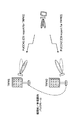
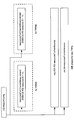
- FIG. 1 shows Rel. 15 It is a figure which shows an example of the CSI report setting in NR.
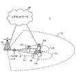
- FIG. 2 is a diagram showing an example of a multi-TRP scenario.
- FIG. 3 is a diagram showing an example of CSI report setting according to the first embodiment.
- FIG. 4 is a diagram showing an example of an RRC parameter indicating a CSI feedback type indication.
- FIG. 5 is a diagram showing an example of joint CSI setting.
- FIG. 6 is a diagram showing an example of CSI report setting according to the second embodiment.
- FIG. 7 is a diagram showing an example of CSI report setting according to the second embodiment.
- FIG. 8 is a diagram showing an example of CSI report setting according to the second embodiment.
- FIG. 9 is a diagram showing an example of CSI report setting according to the second embodiment.
- FIG. 10 is a diagram showing an example of a schematic configuration of a wireless communication system according to an embodiment.
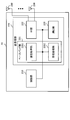
- FIG. 11 is a diagram showing an example of the configuration of the base station according to the embodiment.
- FIG. 12 is a diagram showing an example of the configuration of the user terminal according to the embodiment.
- FIG. 13 is a diagram showing an example of the hardware configuration of the base station and the user terminal according to the embodiment.
- the terminal also referred to as a user terminal, User Equipment (UE), etc.
- the terminal has Channel State Information (CSI) based on the reference signal (Reference Signal (RS)) (or resource for the RS).
- RS Reference Signal
- Is generated also referred to as determination, calculation, estimation, measurement, etc.
- the generated CSI is transmitted (also referred to as reporting, feedback, etc.) to the network (for example, a base station).
- the CSI may be transmitted to the base station using, for example, an uplink control channel (eg, Physical Uplink Control Channel (PUCCH)) or an uplink shared channel (eg, Physical Uplink Shared Channel (PUSCH)).
- PUCCH Physical Uplink Control Channel
- PUSCH Physical Uplink Shared Channel
- the RS used to generate the CSI is, for example, a channel state information reference signal (Channel State Information Reference Signal (CSI-RS)), a synchronization signal / broadcast channel (Synchronization Signal / Physical Broadcast Channel (SS / PBCH)) block, and synchronization. It may be at least one of a signal (Synchronization Signal (SS)), a reference signal for demodulation (DeModulation Reference Signal (DMRS)), and the like.
- CSI-RS Channel State Information Reference Signal
- SS Synchron Signal
- DMRS DeModulation Reference Signal
- CSI-RS may include at least one of Non Zero Power (NZP) CSI-RS and CSI-Interference Management (CSI-IM).
- the SS / PBCH block is a block containing SS and PBCH (and the corresponding DMRS), and may be referred to as an SS block (SSB) or the like.
- the SS may include at least one of a primary synchronization signal (Primary Synchronization Signal (PSS)) and a secondary synchronization signal (Secondary Synchronization Signal (SSS)).
- PSS Primary Synchronization Signal
- SSS Secondary Synchronization Signal
- the CSI includes a channel quality indicator (Channel Quality Indicator (CQI)), a precoding matrix indicator (Precoding Matrix Indicator (PMI)), a CSI-RS resource indicator (CSI-RS Resource Indicator (CRI)), and an SS.
- CQI Channel Quality Indicator
- PMI Precoding Matrix Indicator
- CRI CSI-RS Resource Indicator
- SS / PBCH block resource indicator (SS / PBCH Block Resource Indicator (SSBRI)), layer indicator (Layer Indicator (LI)), rank indicator (Rank Indicator (RI)), L1-RSRP (reference signal reception in layer 1)
- SSBRI SS / PBCH Block Resource Indicator
- LI Layer Indicator
- RI rank indicator
- L1-RSRP reference signal reception in layer 1
- Even if at least one of power (Layer 1 Reference Signal Received Power), L1-RSRQ (Reference Signal Received Quality), L1-SINR (Signal to Interference plus Noise Ratio), L1-SNR (Signal to Noise Ratio), etc. is included. good.
- the UE may receive information regarding the CSI report (report configuration information) and control the CSI report based on the report setting information.
- the report setting information may be, for example, "CSI-ReportConfig" of the information element (Information Element (IE)) of the radio resource control (Radio Resource Control (RRC)).
- IE Information Element
- RRC Radio Resource Control
- RRC IE may be read as RRC parameter, upper layer parameter, and the like.
- the report setting information may include at least one of the following, for example.
- -Information about the type of CSI report (report type information, eg "reportConfigType” in RRC IE)
- -Information on one or more quantities of CSI to be reported (one or more CSI parameters)
- CSI parameters eg, "report Quantity” of RRC IE
- -Information on RS resources used to generate the amount (the CSI parameter)
- source information for example, "CSI-ResourceConfigId” of RRC IE
- -Information about the frequency domain subject to CSI reporting (frequency domain information, for example, "reportFreqConfiguration" of RRC IE)
- the report type information can be a periodic CSI (Periodic CSI (P-CSI)) report, an aperiodic CSI (Aperiodic CSI (A-CSI)) report, or a semi-permanent (semi-persistent, semi-persistent) report.
- P-CSI Period CSI
- Aperiodic CSI Aperiodic CSI
- SP-CSI semi-permanent CSI report
- a stent (Semi-Persistent) CSI report (Semi-Persistent CSI (SP-CSI)) report may be indicated (indicate).
- the reported amount information may specify at least one combination of the above CSI parameters (for example, CRI, RI, PMI, CQI, LI, L1-RSRP, etc.).
- the resource information may be the ID of the resource for RS.
- the RS resource may include, for example, a non-zero power CSI-RS resource or SSB and a CSI-IM resource (for example, a zero power CSI-RS resource).
- the frequency domain information may indicate the frequency granularity of the CSI report.
- the frequency particle size may include, for example, wideband and subband.
- the wide band is the entire CSI reporting band (entire CSI reporting band).
- the wide band may be, for example, the entire carrier (component carrier (CC), cell, serving cell), or the entire bandwidth part (BWP) within a carrier. There may be.
- the wide band may be paraphrased as a CSI reporting band, an entire CSI reporting band (entire CSI reporting band), and the like.
- the sub-band is a part of the wide band, and may be composed of one or more resource blocks (Resource Block (RB) or Physical Resource Block (PRB)).
- the size of the subband may be determined according to the size of the BWP (number of PRBs).
- the frequency domain information may indicate whether to report a wideband or subband PMI (frequency domain information is used, for example, to determine either a wideband PMI report or a subband PMI report) RRC IE. May include "pmi-Format Indicator").
- the UE may determine the frequency particle size of the CSI report (ie, either the wideband PMI report or the subband PMI report) based on at least one of the reported amount information and the frequency domain information.
- wideband PMI reporting is set (determined)
- one wideband PMI may be reported for the entire CSI reporting band.
- subband PMI reporting is configured, a single wideband indication i 1 is reported for the entire CSI reporting band and each subband of one or more subbands within the entire CSI reporting.
- An indication (one subband indication) i 2 (eg, a subband indication of each subband) may be reported.
- the UE performs channel estimation using the received RS and estimates the channel matrix H.
- the UE feeds back an index (PMI) determined based on the estimated channel matrix.
- the PMI may indicate a precoder matrix (simply also referred to as a precoder) that the UE considers appropriate for use in downlink (DL) transmission to the UE.
- a precoder matrix (simply also referred to as a precoder) that the UE considers appropriate for use in downlink (DL) transmission to the UE.
- Each value of PMI may correspond to one precoder matrix.
- the set of PMI values may correspond to a different set of precoder matrices called a precoder codebook (also simply referred to as a codebook).
- a CSI report may include one or more types of CSI.
- the CSI may include at least one of a first type used for single beam selection (type 1 CSI) and a second type used for multi-beam selection (type 2 CSI).
- a single beam may be paraphrased as a single layer, and a multi-beam may be paraphrased as a plurality of beams.
- the type 1 CSI may assume a multi-user multiple input multiple outpiut (MIMO), and the type 2 CSI may assume a multi-user MIMO.
- MIMO multi-user multiple input multiple outpiut
- the above codebook may include a codebook for type 1 CSI (also referred to as a type 1 codebook or the like) and a codebook for type 2 CSI (also referred to as a type 2 codebook or the like).
- the type 1 CSI may include a type 1 single panel CSI and a type 1 multi-panel CSI, and different codebooks (type 1 single-panel codebook, type 1 multi-panel codebook) may be specified.
- type 1 and type I may be read as each other.
- type 2 and type II may be read interchangeably.
- the uplink control information (UCI) type may include at least one of Hybrid Automatic Repeat reQuest ACKnowledgement (HARQ-ACK), scheduling request (SR), and CSI.
- HARQ-ACK Hybrid Automatic Repeat reQuest ACKnowledgement
- SR scheduling request
- CSI CSI
- the UCI may be carried by PUCCH or by PUSCH.
- the UCI can include one CSI part for wideband PMI feedback.
- CSI report # n includes PMI wideband information if reported.
- the UCI can include two CSI parts for subband PMI feedback.
- CSI Part 1 contains wideband PMI information.
- CSI Part 2 includes one wideband PMI information and several subband PMI information.
- CSI Part 1 and CSI Part 2 are separated and encoded.
- the UE sets the report setting of N (N ⁇ 1) CSI report settings and the resource setting of M (M ⁇ 1) CSI resource settings by the upper layer.
- the CSI report settings include channel measurement resource settings (resourcesForChannelMeasurement), interference CSI-IM resource settings (csi-IM-ResourceForInterference), and interference NZP-CSI-RS. Includes settings (nzp-CSI-RS-ResourceForInterference), reportquantity, etc.
- the CSI resource setting includes a list of CSI-RS resource sets (csi-RS-ResourceSetList, eg, NZP-CSI-RS resource set or CSI-IM resource set).
- each CSI-RS resource for channel measurement is associated with CSI-IM resource for each resource in the order of CSI-RS resource and CSI-IM resource in the corresponding resource set. Be done.
- the number of CSI-RS resources for channel measurement is equal to the number of CSI-IM resources.
- the channel measurement resource (CMR) and the interference measurement resource (IMR) have a one-to-one mapping with respect to the interference measurement based on CSI-IM.
- the UE is'cri-RSRP','cri-RI-PMI-CQI','cri-RI-i1','cri-RI-i1-CQI','cri-RI-CQI',or'cri- CSI reporting settings with the reporting quantity (upper layer parameter reportQuantity) set in RI-LI-PMI-CQI'are set and K S (K S > 1) in the corresponding resource set for channel measurement.
- the UE derives CSI parameters other than CRI, subject to the reported CRI.
- CSI k (k ⁇ 0) is of the associated NZP-CSI-RS resource (nzp-CSI-RSResource) in the corresponding NZP-CSI-RS resource set (nzp-CSI-RS-ResourceSet) for channel measurement.
- CSI k corresponds to the set (k + 1) th CMR and the set (k + 1) th IMR.
- Multi TRP In NR, one or more transmission / reception points (Transmission / Reception Point (TRP)) (multi-TRP (multi TRP (MTRP))) use one or more panels (multi-panel) to the UE. It is being considered to perform DL transmission. It is also being considered that the UE transmits UL to one or more TRPs using one or more panels.
- TRP Transmission / Reception Point
- MTRP multi TRP
- the plurality of TRPs may correspond to the same cell identifier (cell Identifier (ID)) or may correspond to different cell IDs.
- the cell ID may be a physical cell ID or a virtual cell ID.
- FIG. 2 is a diagram showing an example of a multi-TRP scenario.
- each TRP and UE assumes that two different beams are available, but is not limited to this.
- Multi-TRPs (TRPs # 1 and # 2) are connected by ideal / non-ideal backhauls, and information, data, etc. may be exchanged.
- Different code words (Code Word (CW)) and different layers may be transmitted from each TRP of the multi-TRP.
- CW Code Word
- NJT non-coherent joint transmission
- TRP1 modulates and maps the first codeword, layer-maps it, and transmits the first PDSCH to the first number of layers (for example, two layers) using the first precoding.
- TRP2 modulates and maps the second codeword, layer-maps the second number of layers (for example, the second layer), and transmits the second PDSCH using the second precoding.
- the plurality of PDSCHs (multi-PDSCHs) to be NCJT may be defined as partially or completely overlapping with respect to at least one of the time and frequency domains. That is, at least one of the time and frequency resources of the first PDSCH from the first TRP and the second PDSCH from the second TRP may overlap.
- first PDSCH and second PDSCH may be assumed to be not quasi-co-located in a pseudo-collocation (Quasi-Co-Location (QCL)) relationship.
- the reception of the multi-PDSCH may be read as the simultaneous reception of PDSCHs that are not of a certain QCL type (for example, QCL type D).
- the UE receives a plurality of PDSCHs (may be referred to as multiple PDSCHs) from a multi-TRP based on one or a plurality of DCIs. Further, in this example, it is assumed that the UE transmits a separate CSI report (CSI report) for each TRP to different TRPs. Such CSI feedback may be referred to as separate feedback, separate CSI feedback, or the like. In the present disclosure, "separate” may be read as "independent" with each other.
- CSI feedback may be used to send CSI reports for both TRPs to one TRP.
- Such CSI feedback may be referred to as joint feedback, joint CSI feedback, or the like.
- the UE transmits a CSI report for TRP # 1 to TRP # 1 using a certain PUCCH (PUCCH1), and sends a CSI report for TRP # 2 to TRP # 2. It is set to transmit using another PUCCH (PUCCH2) (separate feedback). In the case of joint feedback, the UE sends a CSI report for TRP # 1 and a CSI report for TRP # 2 to TRP # 1 or # 2.
- PUCCH1 PUCCH
- PUCH2 PUCCH 2
- the CSI for multiple different TRPs is usually different, so it is not clear how to measure and report the CSI for multiple different TRPs.
- the channel / interference premise changes depending on the transmission decision (traffic) of the peripheral TRP.
- a CSI report for separate feedback (which may be called a separate CSI report) may be set using one CSI report setting (CSI-ReportConfig) associated with one TRP.
- CSI-ReportConfig one CSI report setting associated with one TRP.
- the CSI report setting may correspond to one interference premise for one TRP (that is, a different CSI report setting may be used for each TRP and each interference premise).
- the CSI reporting setting may correspond to the assumption of multiple interferences for one TRP (ie, different CSI reporting settings are used for each TRP, and one CSI reporting setting may have multiple interferences for a TRP). May be associated with the assumptions of).
- a CSI report for joint feedback (which may be called a joint CSI report) may be set using one CSI report setting (CSI-ReportConfig) associated with a plurality of TRPs.
- CSI-ReportConfig one CSI report setting associated with a plurality of TRPs.
- the CSI reporting setting may correspond to one interference premise for each of the plurality of TRPs (that is, the CSI of the interference premise # 1 for TRP # 1 and the CSI of the interference premise # 1 for TRP # 2).
- a CSI report that includes a CSI report is set using a CSI report setting, and a CSI report that includes the CSI of interference premise # 2 for TRP # 1 and the CSI of interference premise # 1 for TRP # 2 uses different CSI report settings. May be set).
- the CSI reporting setting may correspond to a plurality of interference assumptions for each of the plurality of TRPs (that is, two CSIs of interference assumptions # 1 and # 2 for TRP # 1 and interference assumptions # 3 for TRP # 2). , # 4 two CSIs, and a CSI report containing, may be set up using one CSI reporting setting).
- the CSI report setting for the joint CSI report may include resource settings for each TRP (at least one of channel measurement resource settings, interference CSI-IM resource settings, and interference NZP-CSI-RS settings). ..
- the resource setting of a certain TRP may be included in the resource setting group and set.
- the resource setting group may be identified by the resource setting group index to be set.
- the resource setting group may be read as the report group.
- a resource configuration group index (which may also be referred to simply as a group index) is a TRP-related CSI report (a CSI report (or CSI report configuration, CSI resource configuration, CSI-RS resource set, CSI-RS resource, TCI status). , QCL, etc.) may indicate which TRP corresponds to).
- the group index #i may correspond to TRP # i.
- the CSI report setting for the separate CSI report may be referred to as a separate CSI report setting, a separate CSI setting, or the like.
- CSI report settings for joint CSI reports may be referred to as joint CSI report settings, joint CSI settings, and the like.
- CSI single TRP
- CSI_A first TRP
- CSI_2 second TRP
- CSI_C CSI for TRP1
- CSI_D TRP / beam-to-beam interference from TRP1 assuming NCJT transmission of MTRP
- CSI_A and CSI_B may be subjected to separate feedback or joint feedback.
- CSI_C and CSI_D are separately fed back, the following problems may occur.
- the network is required to acquire appropriate RI and PMI to meet the UE capability for NCJT.
- UE operation for example, dropping PDSCH of some layers, not decoding, etc.
- the total rank from MTRP exceeds the above UE capability may be specified.
- the network is required to acquire a CSI for NCJT that is better suited to the channel state.
- the present inventors have conceived a suitable method for measuring and reporting CSI when using multi-panel / TRP.
- a / B and “at least one of A and B” may be read as each other.
- a panel an Uplink (UL) transmitting entity, a TRP, a spatial relationship, a control resource set (COntrol REsource SET (CORESET)), a PDSCH, a code word, a base station, and an antenna port of a certain signal (for example, a reference signal for demodulation).
- a certain signal for example, a reference signal for demodulation.
- DMRS DeModulation Reference Signal
- antenna port group of a certain signal for example, DMRS port group
- group for multiplexing for example, Code Division Multiplexing (CDM)) group, reference signal group,
- the CORESET group the CORESET pool, the CW, the redundant version (redundancy version (RV)), and the layers (MIMO layer, transmission layer, spatial layer
- the panel Identifier (ID) and the panel may be read as each other.
- TRP ID and TRP may be read as each other.
- NCJT, NCJT using multi-TRP, multi-PDSCH using NCJT, multi-PDSCH, a plurality of PDSCHs from multi-TRP, and the like may be read as each other.
- the multi-PDSCH may mean a plurality of PDSCHs in which at least a part (for example, one symbol) of the time resource overlaps, or a plurality of PDSCHs in which all of the time resources (for example, all symbols) overlap. It may mean multiple PDSCHs in which all of the time resources do not overlap, it may mean multiple PDSCHs carrying the same TB or the same CW, or different UE beams (spatial). It may mean a plurality of PDSCHs to which a domain reception filter (QCL parameter) is applied.
- QCL parameter domain reception filter
- the cell, CC, carrier, BWP, and band may be read as each other.
- indexes, IDs, indicators, resource IDs, etc. may be read as each other.
- the beam, TCI, TCI state, DL TCI state, UL TCI state, unified TCI state, QCL, QCL assumption, spatial relationship, spatial relationship information, precoder, etc. may be read as each other.
- lists, groups, sets, subsets, clusters, etc. may be read interchangeably.
- the TRP index, the CORESETPoolIndex, the pool index, the group index, the CSI report setting group index, the CSI report group index, the CSI report setting index, the CSI report setting group index, and the resource setting group index are interchangeably read. May be done.
- the resource setting for channel measurement, the resource for channel measurement, and resourcesForChannelMeasurement may be read as each other.
- the CSI-IM resource setting for interference, the CSI-IM based (CSI-IM based) interference measurement resource, the csi-IM-ResourceForInterference, and the interference measurement resource may be read as each other.
- the NZP-CSI-RS resource setting for interference, the NZP-CSI-RS based (NZP-CSI-RS based) interference measurement resource, the nzp-CSI-RS-ResourcesForInterference, and the interference measurement resource are read as interchangeable with each other. May be
- the CSI report, CSI report setting, CSI setting, resource setting, etc. may be read as each other.
- the first embodiment is an embodiment particularly corresponding to the above-mentioned problem 1.
- the UE may simultaneously set the CSI report setting for the separate CSI report (separate CSI report setting) and the CSI report setting for the joint CSI report (joint CSI report setting).
- the UE may be set only with the CSI report setting for the separate CSI report, or may be set with only the CSI report setting for the joint CSI report.
- the separate CSI report may be used to report at least one of the above-mentioned CSI_A and CSI_B.
- the joint CSI report may be used to report at least one of CSI_A and CSI_B described above.
- the joint CSI report may include a plurality of CSIs, including a first CSI for the first TRP and a second CSI for the second TRP.
- the UE satisfies at least one of the following (at least one constraint below) of the first rank indicated by the first CSI (RI) and the second rank indicated by the second CSI (RI).
- RI first rank indicated by the first CSI
- RI second rank indicated by the second CSI
- Each of the first rank and the second rank does not exceed the value obtained by dividing the maximum number of supported spatial multiplex layers by N (for example, N is the number of TRPs set, the number of CORESET pools, etc.). ), (3)
- Each of the first rank and the second rank does not exceed the value based on the upper layer signaling (for example, RRC, MAC CE, etc.).
- the UE capability in (1) above is described in Rel. 15 It may be the maximum number of supported spatial multiplexing layers for DL reception in NR (maxNumberMIMO-LayersPDSCH). Further, when the maximum number of supported spatial multiplexing layers for DL reception per TRP (for example, which may be represented by the RRC parameter "maxNumberMIMO-LayersPDSCHperTRP") is defined, the above (1) " The "rank indicated by UE capability" may be read as rank x N (N is the same as (2) above) indicated by the capability of the maximum number of supported spatial multiplexing layers for DL reception per TRP. ..
- the "maximum number of supported spatial multiplexing layers" in (1) above is divided by N.
- the value may be read as the maximum number of spatial multiplexing layers supported for DL reception per TRP.
- the value based on the upper layer signaling is one value of the maximum rank that is allowed to be reported, which is common to a plurality of CSIs (plurality of TRPs) in the CSI report (that is, the first rank and the first rank). It may be a set of maximum ranks (see different values for the first and second ranks) that can be reported for each of the multiple CSIs (TRPs). ) May be.
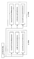
- FIG. 3 is a diagram showing an example of CSI report setting according to the first embodiment.
- the UE is simultaneously set with CSI report settings # 1 and # 2 for separate CSI reports and CSI report settings # 3 for joint CSI reports.
- CSI report setting # 1 may correspond to CSI_A for TRP1
- CSI report setting # 2 may correspond to CSI_B for TRP2.
- CSI reporting setting # 3 may correspond to CSI_C and CSI_D for MTRP. Note that CSI_C and CSI_D comply with at least one of the above (1)-(3) restrictions.
- FIG. 4 is a diagram showing an example of an RRC parameter indicating a CSI feedback type indication.
- the CSI-ReportConfig includes at least an RRC parameter that indicates a CSI feedback type indication.
- the UE may assume that the default feedback type will be used for that CSI reporting setting.
- the default feedback type may be a separate CSI setting, a joint CSI setting, or may be determined based on other parameters in the CSI reporting setting as described below.
- CSI report setting is a separate CSI setting or a joint CSI setting may be implicitly notified by other RRC parameters.
- the UE has up to one CMR (resourcesForChannelMeasurement), one ZP-IMR (csi-IM-ResourcesForInterference), and one NZP-IMR (nzp-CSI-RS-ResourcesForInterference).
- CMR resourcesForChannelMeasurement
- ZP-IMR csi-IM-ResourcesForInterference
- NZP-IMR nzp-CSI-RS-ResourcesForInterference
- the UE has at least one of a plurality of CMRs (resourcesForChannelMeasurement), a plurality of ZP-IMRs (csi-IM-ResourcesForInterference), and a plurality of NZP-IMRs (nzp-CSI-RS-ResourcesForInterference).
- the CSI reporting setting may be determined to be a joint CSI setting. The UE may assume that the CSI report based on the CSI report setting includes a plurality of CSIs.
- a set of CMR, ZP-IMR and NZP-IMR may be set for each TRP. Different sets may be set in association with different resource setting groups.
- the UE can report a plurality of RIs suitable for NCJT transmission by using the joint CSI report.
- the second embodiment is an embodiment particularly corresponding to the above-mentioned problem 2.
- the CMR for one CSI corresponds to the IMR for another CSI (TRP).
- TRP the CMR for one CSI
- TRP the IMR for another CSI
- the two CSIs included in the joint CSI report for NCJT transmission are expected to be well aligned with the actual inter-TRP interference (sufficiently accurate for direct scheduling). Also, network implementation does not require further CSI updates.
- the UE transfers the CMR (resource specified by resourcesForChannelMeasurement) of one resource setting group to the NZP-IMR (resource specified by nzp-CSI-RS-ResourcesForInterference) of another resource setting group. It may be assumed that it is included (or is the same).
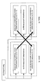
- FIG. 6 is a diagram showing an example of CSI report setting according to the second embodiment. Since FIG. 6 is similar to FIG. 5, no duplicate description will be given.
- TRP # 1 or resource setting group # 1
- TRP # 2 or resource setting group # 1
- ZP-IMR may be set individually for each TRP as shown in FIG.
- FIG. 7 is a diagram showing an example of CSI report setting according to the second embodiment. Since FIG. 7 is similar to FIG. 6, no duplicate description will be given. FIG. 7 is different from FIG. 6 in that the ZP-IMR is set in common (so that it is shared) between the two TRPs.
- a plurality of SSB / CSI-RS IDs are set as CMRs for TRP # 1 (# 2) (multiple CMRs are set), it is for TRP # 2 (# 1).
- NZP-IMR a plurality of SSB / CSI-RS IDs may be set in the same order. For example, the i-th list / ID / set for the CMR of one TRP may be mapped to each other with the i-th list / ID / set for the IMR of another TRP.
- the mapping (correspondence) between the list / ID / set for the CMR of one TRP and the i-th list / ID / set for the IMR of another TRP may be set by higher layer signaling. , May be predetermined by specifications.
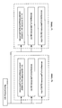
- the UE may assume that for some CSI reporting settings (joint CSI settings) there is no explicit IMR setting for inter-TRP interference. In this case, the specification may specify additional IMR assumptions when joint CSI settings are set.
- the CMR (resources specified by resourcesForChannelMeasurement) for one TRP is an additional NZP for another TRP.
- -It may be assumed that it is included (or is the same) in the IMR.
- the additional NZP-IMR for the other TRP is not explicitly set.
- Information about the additional NZP-IMR may be predetermined by specifications or may be notified to the UE using at least one of RRC, MAC CE and DCI.
- FIG. 8 is a diagram showing an example of CSI report setting according to the second embodiment. Since FIG. 8 is similar to FIG. 6, no duplicate description will be given.
- FIG. 9 is a diagram showing an example of CSI report setting according to the second embodiment. Since FIG. 9 is similar to FIG. 8, no duplicate description will be given. FIG. 9 is different from FIG. 8 in that ZP-IMR and NZP-IMR are set in common (so as to be shared) by the two TRPs.
- the UE can report the CSI for NCJT transmission in consideration of the interference between TRPs by using the joint CSI report.
- wireless communication system Wireless communication system
- communication is performed using any one of the wireless communication methods according to each of the above-described embodiments of the present disclosure or a combination thereof.
- FIG. 10 is a diagram showing an example of a schematic configuration of a wireless communication system according to an embodiment.
- the wireless communication system 1 may be a system that realizes communication using Long Term Evolution (LTE), 5th generation mobile communication system New Radio (5G NR), etc. specified by Third Generation Partnership Project (3GPP). ..
- the radio communication system 1 may support dual connectivity (Multi-RAT Dual Connectivity (MR-DC)) between a plurality of Radio Access Technologies (RATs).
- MR-DC is dual connectivity between LTE (Evolved Universal Terrestrial Radio Access (E-UTRA)) and NR (E-UTRA-NR Dual Connectivity (EN-DC)), and dual connectivity between NR and LTE (NR-E).
- E-UTRA Evolved Universal Terrestrial Radio Access
- EN-DC E-UTRA-NR Dual Connectivity
- NE-DC -UTRA Dual Connectivity
- the LTE (E-UTRA) base station (eNB) is the master node (Master Node (MN)), and the NR base station (gNB) is the secondary node (Secondary Node (SN)).
- the base station (gNB) of NR is MN
- the base station (eNB) of LTE (E-UTRA) is SN.
- the wireless communication system 1 has dual connectivity between a plurality of base stations in the same RAT (for example, dual connectivity (NR-NR Dual Connectivity (NN-DC)) in which both MN and SN are NR base stations (gNB). )) May be supported.
- a plurality of base stations in the same RAT for example, dual connectivity (NR-NR Dual Connectivity (NN-DC)) in which both MN and SN are NR base stations (gNB). )
- NR-NR Dual Connectivity NR-DC
- gNB NR base stations
- the wireless communication system 1 includes a base station 11 that forms a macro cell C1 having a relatively wide coverage, and a base station 12 (12a-12c) that is arranged in the macro cell C1 and forms a small cell C2 that is narrower than the macro cell C1. You may prepare.
- the user terminal 20 may be located in at least one cell. The arrangement, number, and the like of each cell and the user terminal 20 are not limited to the mode shown in the figure.
- the base stations 11 and 12 are not distinguished, they are collectively referred to as the base station 10.
- the user terminal 20 may be connected to at least one of the plurality of base stations 10.
- the user terminal 20 may use at least one of carrier aggregation (Carrier Aggregation (CA)) and dual connectivity (DC) using a plurality of component carriers (Component Carrier (CC)).
- CA Carrier Aggregation
- DC dual connectivity
- CC Component Carrier
- Each CC may be included in at least one of a first frequency band (Frequency Range 1 (FR1)) and a second frequency band (Frequency Range 2 (FR2)).
- the macro cell C1 may be included in FR1 and the small cell C2 may be included in FR2.
- FR1 may be in a frequency band of 6 GHz or less (sub 6 GHz (sub-6 GHz)), and FR2 may be in a frequency band higher than 24 GHz (above-24 GHz).
- the frequency bands and definitions of FR1 and FR2 are not limited to these, and for example, FR1 may correspond to a frequency band higher than FR2.
- the user terminal 20 may perform communication using at least one of Time Division Duplex (TDD) and Frequency Division Duplex (FDD) in each CC.
- TDD Time Division Duplex
- FDD Frequency Division Duplex
- the plurality of base stations 10 may be connected by wire (for example, optical fiber compliant with Common Public Radio Interface (CPRI), X2 interface, etc.) or wirelessly (for example, NR communication).
- wire for example, optical fiber compliant with Common Public Radio Interface (CPRI), X2 interface, etc.
- NR communication for example, when NR communication is used as a backhaul between base stations 11 and 12, the base station 11 corresponding to the higher-level station is an Integrated Access Backhaul (IAB) donor, and the base station 12 corresponding to a relay station (relay) is IAB. It may be called a node.
- IAB Integrated Access Backhaul
- relay station relay station
- the base station 10 may be connected to the core network 30 via another base station 10 or directly.
- the core network 30 may include at least one such as Evolved Packet Core (EPC), 5G Core Network (5GCN), and Next Generation Core (NGC).
- EPC Evolved Packet Core
- 5GCN 5G Core Network
- NGC Next Generation Core
- the user terminal 20 may be a terminal that supports at least one of communication methods such as LTE, LTE-A, and 5G.
- a wireless access method based on Orthogonal Frequency Division Multiplexing may be used.
- OFDM Orthogonal Frequency Division Multiplexing
- DL Downlink
- UL Uplink
- CP-OFDM Cyclic Prefix OFDM
- DFT-s-OFDM Discrete Fourier Transform Spread OFDM
- OFDMA Orthogonal Frequency Division Multiple. Access
- SC-FDMA Single Carrier Frequency Division Multiple Access
- the wireless access method may be called a waveform.
- another wireless access system for example, another single carrier transmission system, another multi-carrier transmission system
- the UL and DL wireless access systems may be used as the UL and DL wireless access systems.
- downlink shared channels Physical Downlink Shared Channel (PDSCH)
- broadcast channels Physical Broadcast Channel (PBCH)
- downlink control channels Physical Downlink Control
- Channel PDCCH
- the uplink shared channel Physical Uplink Shared Channel (PUSCH)
- the uplink control channel Physical Uplink Control Channel (PUCCH)
- the random access channel shared by each user terminal 20 are used.
- Physical Random Access Channel (PRACH) Physical Random Access Channel or the like may be used.
- User data, upper layer control information, System Information Block (SIB), etc. are transmitted by PDSCH.
- User data, upper layer control information, and the like may be transmitted by the PUSCH.
- the Master Information Block (MIB) may be transmitted by the PBCH.
- Lower layer control information may be transmitted by PDCCH.
- the lower layer control information may include, for example, downlink control information (Downlink Control Information (DCI)) including scheduling information of at least one of PDSCH and PUSCH.
- DCI Downlink Control Information
- the DCI that schedules PDSCH may be called DL assignment, DL DCI, etc.
- the DCI that schedules PUSCH may be called UL grant, UL DCI, etc.
- the PDSCH may be read as DL data
- the PUSCH may be read as UL data.
- a control resource set (COntrol REsource SET (CORESET)) and a search space (search space) may be used for PDCCH detection.
- CORESET corresponds to a resource that searches for DCI.
- the search space corresponds to the search area and search method of PDCCH candidates (PDCCH candidates).
- One CORESET may be associated with one or more search spaces. The UE may monitor the CORESET associated with a search space based on the search space settings.
- One search space may correspond to PDCCH candidates corresponding to one or more aggregation levels.
- One or more search spaces may be referred to as a search space set.
- the "search space”, “search space set”, “search space setting”, “search space set setting”, “CORESET”, “CORESET setting”, etc. of the present disclosure may be read as each other.
- channel state information (Channel State Information (CSI)
- delivery confirmation information for example, it may be called Hybrid Automatic Repeat reQuest ACKnowledgement (HARQ-ACK), ACK / NACK, etc.
- scheduling request (Scheduling Request ( Uplink Control Information (UCI) including at least one of SR))
- the PRACH may transmit a random access preamble to establish a connection with the cell.
- downlinks, uplinks, etc. may be expressed without “links”. Further, it may be expressed without adding "Physical" at the beginning of various channels.
- a synchronization signal (Synchronization Signal (SS)), a downlink reference signal (Downlink Reference Signal (DL-RS)), and the like may be transmitted.
- the DL-RS includes a cell-specific reference signal (Cell-specific Reference Signal (CRS)), a channel state information reference signal (Channel State Information Reference Signal (CSI-RS)), and a demodulation reference signal (DeModulation).
- CRS Cell-specific Reference Signal
- CSI-RS Channel State Information Reference Signal
- DeModulation Demodulation reference signal
- Reference Signal (DMRS)), positioning reference signal (Positioning Reference Signal (PRS)), phase tracking reference signal (Phase Tracking Reference Signal (PTRS)), and the like may be transmitted.
- PRS Positioning Reference Signal
- PTRS Phase Tracking Reference Signal
- the synchronization signal may be, for example, at least one of a primary synchronization signal (Primary Synchronization Signal (PSS)) and a secondary synchronization signal (Secondary Synchronization Signal (SSS)).
- PSS Primary Synchronization Signal
- SSS Secondary Synchronization Signal
- the signal block including SS (PSS, SSS) and PBCH (and DMRS for PBCH) may be referred to as SS / PBCH block, SS Block (SSB) and the like.
- SS, SSB and the like may also be called a reference signal.
- a measurement reference signal Sounding Reference Signal (SRS)
- a demodulation reference signal DMRS
- UL-RS Uplink Reference Signal
- UE-specific Reference Signal UE-specific Reference Signal
- FIG. 11 is a diagram showing an example of the configuration of the base station according to the embodiment.
- the base station 10 includes a control unit 110, a transmission / reception unit 120, a transmission / reception antenna 130, and a transmission line interface 140.
- the control unit 110, the transmission / reception unit 120, the transmission / reception antenna 130, and the transmission line interface 140 may each be provided with one or more.
- this example mainly shows the functional blocks of the feature portion in the present embodiment, and it may be assumed that the base station 10 also has other functional blocks necessary for wireless communication. A part of the processing of each part described below may be omitted.
- the control unit 110 controls the entire base station 10.
- the control unit 110 can be composed of a controller, a control circuit, and the like described based on the common recognition in the technical field according to the present disclosure.
- the control unit 110 may control signal generation, scheduling (for example, resource allocation, mapping) and the like.
- the control unit 110 may control transmission / reception, measurement, and the like using the transmission / reception unit 120, the transmission / reception antenna 130, and the transmission line interface 140.
- the control unit 110 may generate data to be transmitted as a signal, control information, a sequence, and the like, and transfer the data to the transmission / reception unit 120.
- the control unit 110 may perform call processing (setting, release, etc.) of the communication channel, state management of the base station 10, management of radio resources, and the like.
- the transmission / reception unit 120 may include a baseband unit 121, a Radio Frequency (RF) unit 122, and a measurement unit 123.
- the baseband unit 121 may include a transmission processing unit 1211 and a reception processing unit 1212.
- the transmitter / receiver 120 includes a transmitter / receiver, an RF circuit, a baseband circuit, a filter, a phase shifter, a measurement circuit, a transmitter / receiver circuit, and the like, which are described based on common recognition in the technical fields according to the present disclosure. be able to.
- the transmission / reception unit 120 may be configured as an integrated transmission / reception unit, or may be composed of a transmission unit and a reception unit.
- the transmission unit may be composed of a transmission processing unit 1211 and an RF unit 122.
- the receiving unit may be composed of a receiving processing unit 1212, an RF unit 122, and a measuring unit 123.
- the transmitting / receiving antenna 130 can be composed of an antenna described based on common recognition in the technical field according to the present disclosure, for example, an array antenna.
- the transmission / reception unit 120 may transmit the above-mentioned downlink channel, synchronization signal, downlink reference signal, and the like.
- the transmission / reception unit 120 may receive the above-mentioned uplink channel, uplink reference signal, and the like.
- the transmission / reception unit 120 may form at least one of a transmission beam and a reception beam by using digital beamforming (for example, precoding), analog beamforming (for example, phase rotation), and the like.
- digital beamforming for example, precoding
- analog beamforming for example, phase rotation
- the transmission / reception unit 120 processes, for example, Packet Data Convergence Protocol (PDCP) layer processing and Radio Link Control (RLC) layer processing (for example, RLC) for data, control information, etc. acquired from control unit 110.
- PDCP Packet Data Convergence Protocol
- RLC Radio Link Control
- MAC Medium Access Control
- HARQ retransmission control for example, HARQ retransmission control
- the transmission / reception unit 120 performs channel coding (may include error correction coding), modulation, mapping, filtering, and discrete Fourier transform (Discrete Fourier Transform (DFT)) for the bit string to be transmitted.
- the base band signal may be output by performing processing (if necessary), inverse fast Fourier transform (IFFT) processing, precoding, digital-analog conversion, and other transmission processing.
- IFFT inverse fast Fourier transform
- the transmission / reception unit 120 may perform modulation, filtering, amplification, etc. on the baseband signal to the radio frequency band, and transmit the signal in the radio frequency band via the transmission / reception antenna 130. ..
- the transmission / reception unit 120 may perform amplification, filtering, demodulation to a baseband signal, or the like on the signal in the radio frequency band received by the transmission / reception antenna 130.
- the transmission / reception unit 120 (reception processing unit 1212) performs analog-digital conversion, fast Fourier transform (FFT) processing, and inverse discrete Fourier transform (IDFT) on the acquired baseband signal. )) Processing (if necessary), filtering, decoding, demodulation, decoding (may include error correction decoding), MAC layer processing, RLC layer processing, PDCP layer processing, and other reception processing are applied. User data and the like may be acquired.
- FFT fast Fourier transform
- IDFT inverse discrete Fourier transform
- the transmission / reception unit 120 may perform measurement on the received signal.
- the measuring unit 123 may perform Radio Resource Management (RRM) measurement, Channel State Information (CSI) measurement, or the like based on the received signal.
- the measuring unit 123 has received power (for example, Reference Signal Received Power (RSRP)) and reception quality (for example, Reference Signal Received Quality (RSRQ), Signal to Interference plus Noise Ratio (SINR), Signal to Noise Ratio (SNR)).
- RSRP Reference Signal Received Power
- RSSQ Reference Signal Received Quality
- SINR Signal to Noise Ratio
- Signal strength for example, Received Signal Strength Indicator (RSSI)
- propagation path information for example, CSI
- the measurement result may be output to the control unit 110.
- the transmission line interface 140 transmits / receives signals (backhaul signaling) to / from a device included in the core network 30, another base station 10 and the like, and provides user data (user plane data) and control plane for the user terminal 20. Data or the like may be acquired or transmitted.
- the transmission unit and the reception unit of the base station 10 in the present disclosure may be composed of at least one of the transmission / reception unit 120, the transmission / reception antenna 130, and the transmission line interface 140.
- the transmission / reception unit 120 may transmit the setting information for the joint CSI report including the first channel state information (Channel State Information (CSI)) and the second CSI to the user terminal 20.
- CSI Channel State Information
- the control unit 110 prepares the joint CSI report created by the terminal on the assumption that the first rank indicated by the first CSI and the second rank indicated by the second CSI are subject to certain restrictions. May be received.
- FIG. 12 is a diagram showing an example of the configuration of the user terminal according to the embodiment.
- the user terminal 20 includes a control unit 210, a transmission / reception unit 220, and a transmission / reception antenna 230.
- the control unit 210, the transmission / reception unit 220, and the transmission / reception antenna 230 may each be provided with one or more.
- this example mainly shows the functional blocks of the feature portion in the present embodiment, and it may be assumed that the user terminal 20 also has other functional blocks necessary for wireless communication. A part of the processing of each part described below may be omitted.
- the control unit 210 controls the entire user terminal 20.
- the control unit 210 can be composed of a controller, a control circuit, and the like described based on the common recognition in the technical field according to the present disclosure.
- the control unit 210 may control signal generation, mapping, and the like.
- the control unit 210 may control transmission / reception, measurement, and the like using the transmission / reception unit 220 and the transmission / reception antenna 230.
- the control unit 210 may generate data to be transmitted as a signal, control information, a sequence, and the like, and transfer the data to the transmission / reception unit 220.
- the transmission / reception unit 220 may include a baseband unit 221 and an RF unit 222, and a measurement unit 223.
- the baseband unit 221 may include a transmission processing unit 2211 and a reception processing unit 2212.
- the transmitter / receiver 220 can be composed of a transmitter / receiver, an RF circuit, a baseband circuit, a filter, a phase shifter, a measurement circuit, a transmitter / receiver circuit, and the like, which are described based on the common recognition in the technical field according to the present disclosure.
- the transmission / reception unit 220 may be configured as an integrated transmission / reception unit, or may be composed of a transmission unit and a reception unit.
- the transmission unit may be composed of a transmission processing unit 2211 and an RF unit 222.
- the receiving unit may be composed of a receiving processing unit 2212, an RF unit 222, and a measuring unit 223.
- the transmitting / receiving antenna 230 can be composed of an antenna described based on common recognition in the technical field according to the present disclosure, for example, an array antenna.
- the transmission / reception unit 220 may receive the above-mentioned downlink channel, synchronization signal, downlink reference signal, and the like.
- the transmission / reception unit 220 may transmit the above-mentioned uplink channel, uplink reference signal, and the like.
- the transmission / reception unit 220 may form at least one of a transmission beam and a reception beam by using digital beamforming (for example, precoding), analog beamforming (for example, phase rotation), and the like.
- digital beamforming for example, precoding
- analog beamforming for example, phase rotation
- the transmission / reception unit 220 (transmission processing unit 2211) performs PDCP layer processing, RLC layer processing (for example, RLC retransmission control), and MAC layer processing (for example, for data, control information, etc. acquired from the control unit 210). , HARQ retransmission control), etc., to generate a bit string to be transmitted.
- RLC layer processing for example, RLC retransmission control
- MAC layer processing for example, for data, control information, etc. acquired from the control unit 210.
- HARQ retransmission control HARQ retransmission control
- the transmission / reception unit 220 (transmission processing unit 2211) performs channel coding (may include error correction coding), modulation, mapping, filtering processing, DFT processing (if necessary), and IFFT processing for the bit string to be transmitted. , Precoding, digital-to-analog conversion, and other transmission processing may be performed to output the baseband signal.
- Whether or not to apply the DFT process may be based on the transform precoding setting.
- the transmission / reception unit 220 transmits the channel using the DFT-s-OFDM waveform.
- the DFT process may be performed as the transmission process, and if not, the DFT process may not be performed as the transmission process.
- the transmission / reception unit 220 may perform modulation, filtering, amplification, etc. on the baseband signal to the radio frequency band, and transmit the signal in the radio frequency band via the transmission / reception antenna 230. ..
- the transmission / reception unit 220 may perform amplification, filtering, demodulation to a baseband signal, or the like on the signal in the radio frequency band received by the transmission / reception antenna 230.
- the transmission / reception unit 220 (reception processing unit 2212) performs analog-to-digital conversion, FFT processing, IDFT processing (if necessary), filtering processing, demapping, demodulation, and decoding (error correction) for the acquired baseband signal. Decoding may be included), MAC layer processing, RLC layer processing, PDCP layer processing, and other reception processing may be applied to acquire user data and the like.
- the transmission / reception unit 220 may perform measurement on the received signal.
- the measuring unit 223 may perform RRM measurement, CSI measurement, or the like based on the received signal.
- the measuring unit 223 may measure received power (for example, RSRP), reception quality (for example, RSRQ, SINR, SNR), signal strength (for example, RSSI), propagation path information (for example, CSI), and the like.
- the measurement result may be output to the control unit 210.
- the transmission unit and the reception unit of the user terminal 20 in the present disclosure may be composed of at least one of the transmission / reception unit 220, the transmission / reception antenna 230, and the transmission line interface 240.
- control unit 210 is subject to certain restrictions, that is, the first rank indicated by the first channel state information (Channel State Information (CSI)) and the second rank indicated by the second CSI.
- CSI Channel State Information
- the creation (generation) of a joint CSI report including the first CSI and the second CSI may be controlled.
- the transmission / reception unit 220 may transmit the joint CSI report.
- the control unit 210 may assume that the total rank of the first rank and the second rank does not exceed the rank indicated by the UE capability.
- control unit 210 sets a CSI report setting that includes information indicating a joint CSI report (CSI feedback type instruction indicating a joint CSI report) or a CSI report setting that does not indicate a separate CSI report, the control unit 210 of the joint CSI report You may control the creation.
- the channel measurement resource (CMR) for the first CSI corresponds to the interference measurement resource (IMR, for example, at least one of NZP-IMR and ZP-IMR) for the second CSI. Assuming that, the creation of the joint CSI report may be controlled.
- each functional block may be realized by using one device that is physically or logically connected, or directly or indirectly (for example, by two or more devices that are physically or logically separated). , Wired, wireless, etc.) and may be realized using these plurality of devices.
- the functional block may be realized by combining the software with the one device or the plurality of devices.
- the functions include judgment, decision, judgment, calculation, calculation, processing, derivation, investigation, search, confirmation, reception, transmission, output, access, solution, selection, selection, establishment, comparison, assumption, expectation, and deemed. , Broadcasting, notifying, communicating, forwarding, configuring, reconfiguring, allocating, mapping, assigning, etc.
- a functional block (constituent unit) for functioning transmission may be referred to as a transmitting unit (transmitting unit), a transmitter (transmitter), or the like.
- the method of realizing each of them is not particularly limited.
- the base station, user terminal, and the like in one embodiment of the present disclosure may function as a computer that processes the wireless communication method of the present disclosure.
- FIG. 13 is a diagram showing an example of the hardware configuration of the base station and the user terminal according to the embodiment.
- the base station 10 and the user terminal 20 described above may be physically configured as a computer device including a processor 1001, a memory 1002, a storage 1003, a communication device 1004, an input device 1005, an output device 1006, a bus 1007, and the like. ..
- the hardware configuration of the base station 10 and the user terminal 20 may be configured to include one or more of the devices shown in the figure, or may be configured not to include some of the devices.
- processor 1001 may be a plurality of processors. Further, the processing may be executed by one processor, or the processing may be executed simultaneously, sequentially, or by using other methods by two or more processors.
- the processor 1001 may be mounted by one or more chips.
- the processor 1001 For each function of the base station 10 and the user terminal 20, for example, by loading predetermined software (program) on hardware such as the processor 1001 and the memory 1002, the processor 1001 performs an operation and communicates via the communication device 1004. It is realized by controlling at least one of reading and writing of data in the memory 1002 and the storage 1003.
- predetermined software program
- Processor 1001 operates, for example, an operating system to control the entire computer.
- the processor 1001 may be configured by a central processing unit (CPU) including an interface with peripheral devices, a control device, an arithmetic unit, a register, and the like.
- CPU central processing unit
- control unit 110 210
- transmission / reception unit 120 220
- the like may be realized by the processor 1001.
- the processor 1001 reads a program (program code), a software module, data, etc. from at least one of the storage 1003 and the communication device 1004 into the memory 1002, and executes various processes according to these.
- a program program code
- the control unit 110 may be realized by a control program stored in the memory 1002 and operating in the processor 1001, and may be realized in the same manner for other functional blocks.
- the memory 1002 is a computer-readable recording medium, such as at least a Read Only Memory (ROM), an Erasable Programmable ROM (EPROM), an Electrically EPROM (EEPROM), a Random Access Memory (RAM), or any other suitable storage medium. It may be composed of one.
- the memory 1002 may be referred to as a register, a cache, a main memory (main storage device), or the like.
- the memory 1002 can store a program (program code), a software module, or the like that can be executed to implement the wireless communication method according to the embodiment of the present disclosure.
- the storage 1003 is a computer-readable recording medium, and is, for example, a flexible disk, a floppy (registered trademark) disk, an optical magnetic disk (for example, a compact disc (Compact Disc ROM (CD-ROM)), a digital versatile disk, etc.). At least one of Blu-ray® disks, removable disks, optical disc drives, smart cards, flash memory devices (eg cards, sticks, key drives), magnetic stripes, databases, servers, and other suitable storage media. It may be composed of.
- the storage 1003 may be referred to as an auxiliary storage device.
- the communication device 1004 is hardware (transmission / reception device) for communicating between computers via at least one of a wired network and a wireless network, and is also referred to as, for example, a network device, a network controller, a network card, a communication module, or the like.
- the communication device 1004 includes, for example, a high frequency switch, a duplexer, a filter, a frequency synthesizer, etc. in order to realize at least one of frequency division duplex (Frequency Division Duplex (FDD)) and time division duplex (Time Division Duplex (TDD)). May be configured to include.
- FDD Frequency Division Duplex
- TDD Time Division Duplex
- the transmission / reception unit 120 (220), the transmission / reception antenna 130 (230), and the like described above may be realized by the communication device 1004.
- the transmission / reception unit 120 (220) may be physically or logically separated from the transmission unit 120a (220a) and the reception unit 120b (220b).
- the input device 1005 is an input device (for example, a keyboard, a mouse, a microphone, a switch, a button, a sensor, etc.) that receives an input from the outside.
- the output device 1006 is an output device (for example, a display, a speaker, a Light Emitting Diode (LED) lamp, etc.) that outputs to the outside.
- the input device 1005 and the output device 1006 may have an integrated configuration (for example, a touch panel).
- each device such as the processor 1001 and the memory 1002 is connected by the bus 1007 for communicating information.
- the bus 1007 may be configured by using a single bus, or may be configured by using a different bus for each device.
- the base station 10 and the user terminal 20 include a microprocessor, a digital signal processor (Digital Signal Processor (DSP)), an Application Specific Integrated Circuit (ASIC), a Programmable Logic Device (PLD), a Field Programmable Gate Array (FPGA), and the like. It may be configured to include hardware, and a part or all of each functional block may be realized by using the hardware. For example, processor 1001 may be implemented using at least one of these hardware.
- DSP Digital Signal Processor
- ASIC Application Specific Integrated Circuit
- PLD Programmable Logic Device
- FPGA Field Programmable Gate Array
- the wireless frame may be composed of one or more periods (frames) in the time domain.
- Each of the one or more periods (frames) constituting the wireless frame may be referred to as a subframe.
- the subframe may be composed of one or more slots in the time domain.
- the subframe may have a fixed time length (eg, 1 ms) that is independent of numerology.
- the numerology may be a communication parameter applied to at least one of transmission and reception of a signal or channel.
- Numerology includes, for example, subcarrier spacing (SubCarrier Spacing (SCS)), bandwidth, symbol length, cyclic prefix length, transmission time interval (Transmission Time Interval (TTI)), number of symbols per TTI, and wireless frame configuration.
- SCS subcarrier Spacing
- TTI Transmission Time Interval
- a specific filtering process performed by the transmitter / receiver in the frequency domain, a specific windowing process performed by the transmitter / receiver in the time domain, and the like may be indicated.
- the slot may be composed of one or more symbols in the time domain (Orthogonal Frequency Division Multiple Access (OFDMA) symbol, Single Carrier Frequency Division Multiple Access (SC-FDMA) symbol, etc.).
- OFDMA Orthogonal Frequency Division Multiple Access
- SC-FDMA Single Carrier Frequency Division Multiple Access
- the slot may be a time unit based on numerology.
- the slot may include a plurality of mini slots. Each minislot may consist of one or more symbols in the time domain. Further, the mini slot may be referred to as a sub slot. A minislot may consist of a smaller number of symbols than the slot.
- a PDSCH (or PUSCH) transmitted in a time unit larger than the minislot may be referred to as a PDSCH (PUSCH) mapping type A.
- the PDSCH (or PUSCH) transmitted using the minislot may be referred to as PDSCH (PUSCH) mapping type B.
- the wireless frame, subframe, slot, minislot and symbol all represent the time unit when transmitting a signal.
- the radio frame, subframe, slot, minislot and symbol may have different names corresponding to each.
- the time units such as frames, subframes, slots, minislots, and symbols in the present disclosure may be read as each other.
- one subframe may be called TTI
- a plurality of consecutive subframes may be called TTI
- one slot or one minislot may be called TTI. That is, at least one of the subframe and TTI may be a subframe (1 ms) in existing LTE, a period shorter than 1 ms (eg, 1-13 symbols), or a period longer than 1 ms. It may be.
- the unit representing TTI may be called a slot, a mini slot, or the like instead of a subframe.
- TTI refers to, for example, the minimum time unit of scheduling in wireless communication.
- the base station schedules each user terminal to allocate radio resources (frequency bandwidth that can be used in each user terminal, transmission power, etc.) in TTI units.
- the definition of TTI is not limited to this.
- the TTI may be a transmission time unit such as a channel-encoded data packet (transport block), a code block, or a code word, or may be a processing unit such as scheduling or link adaptation.
- the time interval for example, the number of symbols
- the transport block, code block, code word, etc. may be shorter than the TTI.
- one or more TTIs may be the minimum time unit for scheduling. Further, the number of slots (number of mini-slots) constituting the minimum time unit of the scheduling may be controlled.
- a TTI having a time length of 1 ms may be referred to as a normal TTI (TTI in 3GPP Rel. 8-12), a normal TTI, a long TTI, a normal subframe, a normal subframe, a long subframe, a slot, or the like.
- a TTI shorter than a normal TTI may be referred to as a shortened TTI, a short TTI, a partial TTI (partial or fractional TTI), a shortened subframe, a short subframe, a minislot, a subslot, a slot, or the like.
- the long TTI (for example, normal TTI, subframe, etc.) may be read as a TTI having a time length of more than 1 ms, and the short TTI (for example, shortened TTI, etc.) is less than the TTI length of the long TTI and 1 ms. It may be read as a TTI having the above TTI length.
- a resource block is a resource allocation unit in the time domain and the frequency domain, and may include one or a plurality of continuous subcarriers in the frequency domain.
- the number of subcarriers contained in the RB may be the same regardless of the numerology, and may be, for example, 12.
- the number of subcarriers contained in the RB may be determined based on numerology.
- the RB may include one or more symbols in the time domain, and may have a length of 1 slot, 1 mini slot, 1 subframe or 1 TTI.
- Each 1TTI, 1 subframe, etc. may be composed of one or a plurality of resource blocks.
- One or more RBs are a physical resource block (Physical RB (PRB)), a sub-carrier group (Sub-Carrier Group (SCG)), a resource element group (Resource Element Group (REG)), a PRB pair, and an RB. It may be called a pair or the like.
- Physical RB Physical RB (PRB)
- SCG sub-carrier Group
- REG resource element group
- the resource block may be composed of one or a plurality of resource elements (Resource Element (RE)).
- RE Resource Element
- 1RE may be a radio resource area of 1 subcarrier and 1 symbol.
- Bandwidth Part (which may also be called partial bandwidth) represents a subset of consecutive common resource blocks (RBs) for a neurology in a carrier. May be good.
- the common RB may be specified by the index of the RB with respect to the common reference point of the carrier.
- PRBs may be defined in a BWP and numbered within that BWP.
- the BWP may include UL BWP (BWP for UL) and DL BWP (BWP for DL).
- BWP UL BWP
- BWP for DL DL BWP
- One or more BWPs may be set in one carrier for the UE.
- At least one of the configured BWPs may be active, and the UE may not expect to send or receive a given signal / channel outside the active BWP.
- “cell”, “carrier” and the like in this disclosure may be read as “BWP”.
- the above-mentioned structures such as wireless frames, subframes, slots, mini slots, and symbols are merely examples.
- the number of subframes contained in a wireless frame the number of slots per subframe or wireless frame, the number of minislots contained in a slot, the number of symbols and RBs contained in a slot or minislot, and included in the RB.
- the number of subcarriers, the number of symbols in the TTI, the symbol length, the cyclic prefix (CP) length, and other configurations can be changed in various ways.
- the information, parameters, etc. described in the present disclosure may be expressed using absolute values, relative values from predetermined values, or using other corresponding information. It may be represented. For example, radio resources may be indicated by a given index.
- the information, signals, etc. described in this disclosure may be represented using any of a variety of different techniques.
- data, instructions, commands, information, signals, bits, symbols, chips, etc. that may be referred to throughout the above description are voltages, currents, electromagnetic waves, magnetic fields or magnetic particles, light fields or photons, or any of these. It may be represented by a combination of.
- information, signals, etc. can be output from the upper layer to the lower layer and from the lower layer to at least one of the upper layers.
- Information, signals, etc. may be input / output via a plurality of network nodes.
- Input / output information, signals, etc. may be stored in a specific location (for example, memory) or may be managed using a management table. Input / output information, signals, etc. can be overwritten, updated, or added. The output information, signals, etc. may be deleted. The input information, signals, etc. may be transmitted to other devices.
- the notification of information is not limited to the mode / embodiment described in the present disclosure, and may be performed by using other methods.
- the notification of information in the present disclosure includes physical layer signaling (for example, downlink control information (DCI)), uplink control information (Uplink Control Information (UCI))), and higher layer signaling (for example, Radio Resource Control). (RRC) signaling, broadcast information (Master Information Block (MIB), System Information Block (SIB), etc.), Medium Access Control (MAC) signaling), other signals or combinations thereof May be carried out by.
- DCI downlink control information
- UCI Uplink Control Information
- RRC Radio Resource Control
- MIB Master Information Block
- SIB System Information Block
- MAC Medium Access Control
- the physical layer signaling may be referred to as Layer 1 / Layer 2 (L1 / L2) control information (L1 / L2 control signal), L1 control information (L1 control signal), and the like.
- the RRC signaling may be called an RRC message, and may be, for example, an RRC connection setup (RRC Connection Setup) message, an RRC connection reconfiguration (RRC Connection Reconfiguration) message, or the like.
- MAC signaling may be notified using, for example, a MAC control element (MAC Control Element (CE)).
- CE MAC Control Element
- the notification of predetermined information is not limited to the explicit notification, but implicitly (for example, by not notifying the predetermined information or another information). May be done (by notification of).
- the determination may be made by a value represented by 1 bit (0 or 1), or by a boolean value represented by true or false. , May be done by numerical comparison (eg, comparison with a given value).
- Software whether referred to as software, firmware, middleware, microcode, hardware description language, or other names, is an instruction, instruction set, code, code segment, program code, program, subprogram, software module.
- Applications, software applications, software packages, routines, subroutines, objects, executable files, execution threads, procedures, functions, etc. should be broadly interpreted.
- software, instructions, information, etc. may be transmitted and received via a transmission medium.
- a transmission medium For example, a website where software uses at least one of wired technology (coaxial cable, fiber optic cable, twisted pair, digital subscriber line (DSL), etc.) and wireless technology (infrared, microwave, etc.).
- wired technology coaxial cable, fiber optic cable, twisted pair, digital subscriber line (DSL), etc.
- wireless technology infrared, microwave, etc.
- the terms “system” and “network” used in this disclosure may be used interchangeably.
- the “network” may mean a device (eg, a base station) included in the network.
- precoding "precoding weight”
- QCL Quality of Co-Co-Location
- TCI state Transmission Configuration Indication state
- space "Spatial relation”, “spatial domain filter”, “transmission power”, “phase rotation”, "antenna port”, “antenna port group”, “layer”, “number of layers”
- Terms such as “rank”, “resource”, “resource set”, “resource group”, “beam”, “beam width”, “beam angle”, "antenna”, “antenna element", “panel” are compatible.
- Base station BS
- radio base station fixed station
- NodeB NodeB
- eNB eNodeB
- gNB gNodeB
- Access point "Transmission point (Transmission Point (TP))
- RP Reception point
- TRP Transmission / Reception Point
- Panel , "Cell”, “sector”, “cell group”, “carrier”, “component carrier” and the like
- Base stations are sometimes referred to by terms such as macrocells, small cells, femtocells, and picocells.
- the base station can accommodate one or more (for example, three) cells.
- a base station accommodates multiple cells, the entire coverage area of the base station can be divided into multiple smaller areas, each smaller area being a base station subsystem (eg, a small indoor base station (Remote Radio)).
- Communication services can also be provided by Head (RRH))).
- RRH Head
- the term "cell” or “sector” refers to part or all of the coverage area of at least one of the base stations and base station subsystems that provide communication services in this coverage.
- MS mobile station
- UE user equipment
- terminal terminal
- Mobile stations include subscriber stations, mobile units, subscriber units, wireless units, remote units, mobile devices, wireless devices, wireless communication devices, remote devices, mobile subscriber stations, access terminals, mobile terminals, wireless terminals, remote terminals. , Handset, user agent, mobile client, client or some other suitable term.
- At least one of the base station and the mobile station may be called a transmitting device, a receiving device, a wireless communication device, or the like.
- At least one of the base station and the mobile station may be a device mounted on the mobile body, the mobile body itself, or the like.
- the moving body may be a vehicle (for example, a car, an airplane, etc.), an unmanned moving body (for example, a drone, an autonomous vehicle, etc.), or a robot (manned or unmanned type). ) May be.
- at least one of the base station and the mobile station includes a device that does not necessarily move during communication operation.
- at least one of the base station and the mobile station may be an Internet of Things (IoT) device such as a sensor.
- IoT Internet of Things
- the base station in the present disclosure may be read by the user terminal.
- the communication between the base station and the user terminal is replaced with the communication between a plurality of user terminals (for example, it may be called Device-to-Device (D2D), Vehicle-to-Everything (V2X), etc.).
- D2D Device-to-Device
- V2X Vehicle-to-Everything
- Each aspect / embodiment of the present disclosure may be applied to the configuration.
- the user terminal 20 may have the function of the base station 10 described above.
- words such as "up” and “down” may be read as words corresponding to communication between terminals (for example, "side”).
- the upstream channel, the downstream channel, and the like may be read as a side channel.
- the user terminal in the present disclosure may be read as a base station.
- the base station 10 may have the functions of the user terminal 20 described above.
- the operation performed by the base station may be performed by its upper node (upper node) in some cases.
- various operations performed for communication with a terminal are performed by the base station and one or more network nodes other than the base station (for example,).
- Mobility Management Entity (MME), Serving-Gateway (S-GW), etc. can be considered, but it is not limited to these), or it is clear that it can be performed by a combination thereof.
- each aspect / embodiment described in the present disclosure may be used alone, in combination, or switched with execution. Further, the order of the processing procedures, sequences, flowcharts, etc. of each aspect / embodiment described in the present disclosure may be changed as long as there is no contradiction. For example, the methods described in the present disclosure present elements of various steps using exemplary order, and are not limited to the particular order presented.
- LTE Long Term Evolution
- LTE-A LTE-Advanced
- SUPER 3G IMT-Advanced
- 4G 4th generation mobile communication system
- 5G 5th generation mobile communication system
- 6G 6th generation mobile communication system
- xG xG (xG (x is, for example, integer, fraction)
- Future Radio Access FAA
- RAT New -Radio Access Technology
- NR New Radio
- NX New radio access
- FX Future generation radio access
- GSM registered trademark
- CDMA2000 Code Division Multiple Access
- UMB Ultra Mobile Broadband
- LTE 802.11 Wi-Fi®
- LTE 802.16 WiMAX®
- LTE 802.20 Ultra-WideBand (UWB), Bluetooth®, and other suitable radios. It may be applied to a system using a communication method, a next-generation system extended based on these, and the like.
- UMB Ultra-WideBand
- references to elements using designations such as “first” and “second” as used in this disclosure does not generally limit the quantity or order of those elements. These designations can be used in the present disclosure as a convenient way to distinguish between two or more elements. Thus, references to the first and second elements do not mean that only two elements can be adopted or that the first element must somehow precede the second element.
- determining used in this disclosure may include a wide variety of actions.
- judgment (decision) means judgment (judging), calculation (calculating), calculation (computing), processing (processing), derivation (deriving), investigation (investigating), search (looking up, search, inquiry) ( For example, searching in a table, database or another data structure), ascertaining, etc. may be considered to be "judgment”.
- judgment (decision) includes receiving (for example, receiving information), transmitting (for example, transmitting information), input (input), output (output), and access (for example). It may be regarded as “judgment (decision)” such as “accessing” (for example, accessing data in memory).
- judgment (decision) is regarded as “judgment (decision)” of solving, selecting, selecting, establishing, comparing, and the like. May be good. That is, “judgment (decision)” may be regarded as “judgment (decision)” of some action.
- the "maximum transmission power" described in the present disclosure may mean the maximum value of the transmission power, may mean the nominal UE maximum transmit power, or may mean the rated maximum transmission power (the). It may mean rated UE maximum transmit power).
- connection are any direct or indirect connection or connection between two or more elements. Means, and can include the presence of one or more intermediate elements between two elements that are “connected” or “joined” to each other.
- the connection or connection between the elements may be physical, logical, or a combination thereof. For example, "connection” may be read as "access”.
- the radio frequency domain microwaves. It can be considered to be “connected” or “coupled” to each other using frequency, electromagnetic energy having wavelengths in the light (both visible and invisible) regions, and the like.
- the term "A and B are different” may mean “A and B are different from each other”.
- the term may mean that "A and B are different from C”.
- Terms such as “separate” and “combined” may be interpreted in the same way as “different”.
Landscapes
- Engineering & Computer Science (AREA)
- Computer Networks & Wireless Communication (AREA)
- Signal Processing (AREA)
- Physics & Mathematics (AREA)
- Mathematical Physics (AREA)
- Mobile Radio Communication Systems (AREA)
Abstract
Priority Applications (5)
| Application Number | Priority Date | Filing Date | Title |
|---|---|---|---|
| CN202080101346.4A CN115699843B (zh) | 2020-04-03 | 2020-04-03 | 终端、无线通信方法、基站以及系统 |
| PCT/JP2020/015360 WO2021199436A1 (fr) | 2020-04-03 | 2020-04-03 | Terminal, procédé de communication radio et station de base |
| JP2022511487A JP7546043B2 (ja) | 2020-04-03 | 2020-04-03 | 端末、無線通信方法、基地局及びシステム |
| US17/995,233 US20230155654A1 (en) | 2020-04-03 | 2020-04-03 | Terminal, radio communication method, and base station |
| US18/744,169 US12267134B2 (en) | 2020-04-03 | 2024-06-14 | Terminal, radio communication method, base station, and system |
Applications Claiming Priority (1)
| Application Number | Priority Date | Filing Date | Title |
|---|---|---|---|
| PCT/JP2020/015360 WO2021199436A1 (fr) | 2020-04-03 | 2020-04-03 | Terminal, procédé de communication radio et station de base |
Related Child Applications (2)
| Application Number | Title | Priority Date | Filing Date |
|---|---|---|---|
| US17/995,233 A-371-Of-International US20230155654A1 (en) | 2020-04-03 | 2020-04-03 | Terminal, radio communication method, and base station |
| US18/744,169 Continuation US12267134B2 (en) | 2020-04-03 | 2024-06-14 | Terminal, radio communication method, base station, and system |
Publications (1)
| Publication Number | Publication Date |
|---|---|
| WO2021199436A1 true WO2021199436A1 (fr) | 2021-10-07 |
Family
ID=77928692
Family Applications (1)
| Application Number | Title | Priority Date | Filing Date |
|---|---|---|---|
| PCT/JP2020/015360 Ceased WO2021199436A1 (fr) | 2020-04-03 | 2020-04-03 | Terminal, procédé de communication radio et station de base |
Country Status (4)
| Country | Link |
|---|---|
| US (2) | US20230155654A1 (fr) |
| JP (1) | JP7546043B2 (fr) |
| CN (1) | CN115699843B (fr) |
| WO (1) | WO2021199436A1 (fr) |
Families Citing this family (3)
| Publication number | Priority date | Publication date | Assignee | Title |
|---|---|---|---|---|
| EP4238226A1 (fr) * | 2020-10-30 | 2023-09-06 | Lenovo (Singapore) Pte. Ltd. | Configuration d'un rapport d'informations d'état de canal |
| US20240154667A1 (en) * | 2021-03-10 | 2024-05-09 | Ntt Docomo, Inc. | Terminal, radio communication method, and base station |
| CN116830743A (zh) * | 2023-04-10 | 2023-09-29 | 北京小米移动软件有限公司 | 调度方法以及装置、通信设备及存储介质 |
Citations (2)
| Publication number | Priority date | Publication date | Assignee | Title |
|---|---|---|---|---|
| US20190109626A1 (en) * | 2017-09-29 | 2019-04-11 | Lg Electronics Inc. | Method and apparatus for reporting channel state information in a wireless communication system |
| US20190260448A1 (en) * | 2018-02-16 | 2019-08-22 | Samsung Electronics Co., Ltd. | Method and apparatus for resource-based csi acquisition in advanced wireless communication systems |
Family Cites Families (5)
| Publication number | Priority date | Publication date | Assignee | Title |
|---|---|---|---|---|
| US10103857B2 (en) * | 2015-09-16 | 2018-10-16 | Samsung Electronics Co., Ltd. | Signaling methods and apparatus for advanced MIMO communication systems |
| US10778293B2 (en) * | 2018-02-16 | 2020-09-15 | Nokia Technologies Oy | Methods and apparatuses for dynamic transmit diversity fallback |
| WO2020029176A1 (fr) * | 2018-08-09 | 2020-02-13 | Qualcomm Incorporated | Rétroaction d'informations d'état de canal pour des transmissions conjointes non cohérentes |
| US11350418B2 (en) * | 2019-01-24 | 2022-05-31 | Samsung Electronics Co., Ltd. | Method and apparatus for channel measurement and reporting in coreset basis |
| WO2021159433A1 (fr) * | 2020-02-14 | 2021-08-19 | Qualcomm Incorporated | Communication multicouche |
-
2020
- 2020-04-03 WO PCT/JP2020/015360 patent/WO2021199436A1/fr not_active Ceased
- 2020-04-03 CN CN202080101346.4A patent/CN115699843B/zh active Active
- 2020-04-03 JP JP2022511487A patent/JP7546043B2/ja active Active
- 2020-04-03 US US17/995,233 patent/US20230155654A1/en not_active Abandoned
-
2024
- 2024-06-14 US US18/744,169 patent/US12267134B2/en active Active
Patent Citations (2)
| Publication number | Priority date | Publication date | Assignee | Title |
|---|---|---|---|---|
| US20190109626A1 (en) * | 2017-09-29 | 2019-04-11 | Lg Electronics Inc. | Method and apparatus for reporting channel state information in a wireless communication system |
| US20190260448A1 (en) * | 2018-02-16 | 2019-08-22 | Samsung Electronics Co., Ltd. | Method and apparatus for resource-based csi acquisition in advanced wireless communication systems |
Non-Patent Citations (2)
| Title |
|---|
| HUAWEI, HISILICON: "CSI measurement enhancement for multi-TRP/panel transmission", 3GPP DRAFT; R1-1906038, 3RD GENERATION PARTNERSHIP PROJECT (3GPP), MOBILE COMPETENCE CENTRE ; 650, ROUTE DES LUCIOLES ; F-06921 SOPHIA-ANTIPOLIS CEDEX ; FRANCE, vol. RAN WG1, no. Reno, USA; 20190513 - 20190517, 3 May 2019 (2019-05-03), Mobile Competence Centre ; 650, route des Lucioles ; F-06921 Sophia-Antipolis Cedex ; France , XP051708080 * |
| NEC: "Discussion on feedback for multi-TRP transmission", 3GPP DRAFT; R1-1906401, 3RD GENERATION PARTNERSHIP PROJECT (3GPP), MOBILE COMPETENCE CENTRE ; 650, ROUTE DES LUCIOLES ; F-06921 SOPHIA-ANTIPOLIS CEDEX ; FRANCE, vol. RAN WG1, no. Reno, USA; 20190513 - 20190517, 3 May 2019 (2019-05-03), Mobile Competence Centre ; 650, route des Lucioles ; F-06921 Sophia-Antipolis Cedex ; France , XP051708436 * |
Also Published As
| Publication number | Publication date |
|---|---|
| JPWO2021199436A1 (fr) | 2021-10-07 |
| JP7546043B2 (ja) | 2024-09-05 |
| US20240333357A1 (en) | 2024-10-03 |
| CN115699843A (zh) | 2023-02-03 |
| US20230155654A1 (en) | 2023-05-18 |
| US12267134B2 (en) | 2025-04-01 |
| CN115699843B (zh) | 2025-07-18 |
Similar Documents
| Publication | Publication Date | Title |
|---|---|---|
| US20230046218A1 (en) | Terminal, radio communication method, and base station | |
| WO2021106092A1 (fr) | Terminal et procédé de communication sans fil | |
| WO2021220474A1 (fr) | Terminal, procédé de communication sans fil et station de base | |
| WO2021166244A1 (fr) | Terminal, procédé de communication sans fil et station de base | |
| WO2021106168A1 (fr) | Terminal et procédé de communication sans fil | |
| WO2022070361A1 (fr) | Terminal, procédé de communication radio et station de base | |
| WO2021229820A1 (fr) | Terminal, procédé de communication radio et station de base | |
| WO2022153458A1 (fr) | Terminal, procédé de communication sans fil et station de base | |
| WO2022070360A1 (fr) | Terminal, procédé de communication radio et station de base | |
| WO2021220856A1 (fr) | Terminal, procédé de communication sans fil et station de base | |
| WO2021161451A1 (fr) | Terminal, procédé de communication sans fil, et station de base | |
| WO2022029979A1 (fr) | Terminal, procédé de communication sans fil, et station de base | |
| WO2021205598A1 (fr) | Terminal, procédé de communication sans fil et station de base | |
| WO2021215379A1 (fr) | Terminal, procédé de communication sans fil, et station de base | |
| WO2021171566A1 (fr) | Terminal, procédé de communication sans fil et station de base | |
| WO2021210108A1 (fr) | Terminal, procédé de communication sans fil, et station de base | |
| JP7546043B2 (ja) | 端末、無線通信方法、基地局及びシステム | |
| WO2022208786A1 (fr) | Terminal, procédé de communication sans fil et station de base | |
| WO2021220475A1 (fr) | Terminal, procédé de communication sans fil et station de base | |
| WO2021205604A1 (fr) | Terminal, procédé de communication radio et station de base | |
| WO2021192310A1 (fr) | Terminal, procédé de communication sans fil et station de base | |
| JP7668879B2 (ja) | 端末、無線通信方法、基地局及びシステム | |
| WO2022224750A1 (fr) | Terminal, procédé de communication sans fil et station de base | |
| WO2021215377A1 (fr) | Terminal, procédé de communication sans fil, et station de base | |
| WO2021205608A1 (fr) | Terminal, procédé de communication radio et station de base |
Legal Events
| Date | Code | Title | Description |
|---|---|---|---|
| 121 | Ep: the epo has been informed by wipo that ep was designated in this application |
Ref document number: 20928922 Country of ref document: EP Kind code of ref document: A1 |
|
| ENP | Entry into the national phase |
Ref document number: 2022511487 Country of ref document: JP Kind code of ref document: A |
|
| NENP | Non-entry into the national phase |
Ref country code: DE |
|
| 122 | Ep: pct application non-entry in european phase |
Ref document number: 20928922 Country of ref document: EP Kind code of ref document: A1 |
|
| WWG | Wipo information: grant in national office |
Ref document number: 202080101346.4 Country of ref document: CN |