WO2021199493A1 - 電源装置及びこれを備える車両並びに蓄電装置 - Google Patents
電源装置及びこれを備える車両並びに蓄電装置 Download PDFInfo
- Publication number
- WO2021199493A1 WO2021199493A1 PCT/JP2020/043710 JP2020043710W WO2021199493A1 WO 2021199493 A1 WO2021199493 A1 WO 2021199493A1 JP 2020043710 W JP2020043710 W JP 2020043710W WO 2021199493 A1 WO2021199493 A1 WO 2021199493A1
- Authority
- WO
- WIPO (PCT)
- Prior art keywords
- power supply
- supply device
- end plate
- battery
- power
- Prior art date
- Legal status (The legal status is an assumption and is not a legal conclusion. Google has not performed a legal analysis and makes no representation as to the accuracy of the status listed.)
- Ceased
Links
Images







Classifications
-
- H—ELECTRICITY
- H01—ELECTRIC ELEMENTS
- H01M—PROCESSES OR MEANS, e.g. BATTERIES, FOR THE DIRECT CONVERSION OF CHEMICAL ENERGY INTO ELECTRICAL ENERGY
- H01M50/00—Constructional details or processes of manufacture of the non-active parts of electrochemical cells other than fuel cells, e.g. hybrid cells
- H01M50/20—Mountings; Secondary casings or frames; Racks, modules or packs; Suspension devices; Shock absorbers; Transport or carrying devices; Holders
- H01M50/262—Mountings; Secondary casings or frames; Racks, modules or packs; Suspension devices; Shock absorbers; Transport or carrying devices; Holders with fastening means, e.g. locks
- H01M50/264—Mountings; Secondary casings or frames; Racks, modules or packs; Suspension devices; Shock absorbers; Transport or carrying devices; Holders with fastening means, e.g. locks for cells or batteries, e.g. straps, tie rods or peripheral frames
-
- B—PERFORMING OPERATIONS; TRANSPORTING
- B60—VEHICLES IN GENERAL
- B60K—ARRANGEMENT OR MOUNTING OF PROPULSION UNITS OR OF TRANSMISSIONS IN VEHICLES; ARRANGEMENT OR MOUNTING OF PLURAL DIVERSE PRIME-MOVERS IN VEHICLES; AUXILIARY DRIVES FOR VEHICLES; INSTRUMENTATION OR DASHBOARDS FOR VEHICLES; ARRANGEMENTS IN CONNECTION WITH COOLING, AIR INTAKE, GAS EXHAUST OR FUEL SUPPLY OF PROPULSION UNITS IN VEHICLES
- B60K1/00—Arrangement or mounting of electrical propulsion units
- B60K1/04—Arrangement or mounting of electrical propulsion units of the electric storage means for propulsion
-
- B—PERFORMING OPERATIONS; TRANSPORTING
- B60—VEHICLES IN GENERAL
- B60L—PROPULSION OF ELECTRICALLY-PROPELLED VEHICLES; SUPPLYING ELECTRIC POWER FOR AUXILIARY EQUIPMENT OF ELECTRICALLY-PROPELLED VEHICLES; ELECTRODYNAMIC BRAKE SYSTEMS FOR VEHICLES IN GENERAL; MAGNETIC SUSPENSION OR LEVITATION FOR VEHICLES; MONITORING OPERATING VARIABLES OF ELECTRICALLY-PROPELLED VEHICLES; ELECTRIC SAFETY DEVICES FOR ELECTRICALLY-PROPELLED VEHICLES
- B60L58/00—Methods or circuit arrangements for monitoring or controlling batteries or fuel cells, specially adapted for electric vehicles
- B60L58/10—Methods or circuit arrangements for monitoring or controlling batteries or fuel cells, specially adapted for electric vehicles for monitoring or controlling batteries
-
- H—ELECTRICITY
- H01—ELECTRIC ELEMENTS
- H01M—PROCESSES OR MEANS, e.g. BATTERIES, FOR THE DIRECT CONVERSION OF CHEMICAL ENERGY INTO ELECTRICAL ENERGY
- H01M10/00—Secondary cells; Manufacture thereof
- H01M10/42—Methods or arrangements for servicing or maintenance of secondary cells or secondary half-cells
- H01M10/44—Methods for charging or discharging
- H01M10/441—Methods for charging or discharging for several batteries or cells simultaneously or sequentially
-
- H—ELECTRICITY
- H01—ELECTRIC ELEMENTS
- H01M—PROCESSES OR MEANS, e.g. BATTERIES, FOR THE DIRECT CONVERSION OF CHEMICAL ENERGY INTO ELECTRICAL ENERGY
- H01M50/00—Constructional details or processes of manufacture of the non-active parts of electrochemical cells other than fuel cells, e.g. hybrid cells
- H01M50/20—Mountings; Secondary casings or frames; Racks, modules or packs; Suspension devices; Shock absorbers; Transport or carrying devices; Holders
- H01M50/204—Racks, modules or packs for multiple batteries or multiple cells
- H01M50/207—Racks, modules or packs for multiple batteries or multiple cells characterised by their shape
- H01M50/209—Racks, modules or packs for multiple batteries or multiple cells characterised by their shape adapted for prismatic or rectangular cells
-
- H—ELECTRICITY
- H01—ELECTRIC ELEMENTS
- H01M—PROCESSES OR MEANS, e.g. BATTERIES, FOR THE DIRECT CONVERSION OF CHEMICAL ENERGY INTO ELECTRICAL ENERGY
- H01M50/00—Constructional details or processes of manufacture of the non-active parts of electrochemical cells other than fuel cells, e.g. hybrid cells
- H01M50/20—Mountings; Secondary casings or frames; Racks, modules or packs; Suspension devices; Shock absorbers; Transport or carrying devices; Holders
- H01M50/218—Mountings; Secondary casings or frames; Racks, modules or packs; Suspension devices; Shock absorbers; Transport or carrying devices; Holders characterised by the material
- H01M50/22—Mountings; Secondary casings or frames; Racks, modules or packs; Suspension devices; Shock absorbers; Transport or carrying devices; Holders characterised by the material of the casings or racks
- H01M50/222—Inorganic material
- H01M50/224—Metals
-
- H—ELECTRICITY
- H01—ELECTRIC ELEMENTS
- H01M—PROCESSES OR MEANS, e.g. BATTERIES, FOR THE DIRECT CONVERSION OF CHEMICAL ENERGY INTO ELECTRICAL ENERGY
- H01M50/00—Constructional details or processes of manufacture of the non-active parts of electrochemical cells other than fuel cells, e.g. hybrid cells
- H01M50/20—Mountings; Secondary casings or frames; Racks, modules or packs; Suspension devices; Shock absorbers; Transport or carrying devices; Holders
- H01M50/233—Mountings; Secondary casings or frames; Racks, modules or packs; Suspension devices; Shock absorbers; Transport or carrying devices; Holders characterised by physical properties of casings or racks, e.g. dimensions
-
- H—ELECTRICITY
- H01—ELECTRIC ELEMENTS
- H01M—PROCESSES OR MEANS, e.g. BATTERIES, FOR THE DIRECT CONVERSION OF CHEMICAL ENERGY INTO ELECTRICAL ENERGY
- H01M50/00—Constructional details or processes of manufacture of the non-active parts of electrochemical cells other than fuel cells, e.g. hybrid cells
- H01M50/20—Mountings; Secondary casings or frames; Racks, modules or packs; Suspension devices; Shock absorbers; Transport or carrying devices; Holders
- H01M50/249—Mountings; Secondary casings or frames; Racks, modules or packs; Suspension devices; Shock absorbers; Transport or carrying devices; Holders specially adapted for aircraft or vehicles, e.g. cars or trains
-
- H—ELECTRICITY
- H01—ELECTRIC ELEMENTS
- H01M—PROCESSES OR MEANS, e.g. BATTERIES, FOR THE DIRECT CONVERSION OF CHEMICAL ENERGY INTO ELECTRICAL ENERGY
- H01M2220/00—Batteries for particular applications
- H01M2220/20—Batteries in motive systems, e.g. vehicle, ship, plane
-
- H—ELECTRICITY
- H01—ELECTRIC ELEMENTS
- H01M—PROCESSES OR MEANS, e.g. BATTERIES, FOR THE DIRECT CONVERSION OF CHEMICAL ENERGY INTO ELECTRICAL ENERGY
- H01M2250/00—Fuel cells for particular applications; Specific features of fuel cell system
- H01M2250/20—Fuel cells in motive systems, e.g. vehicle, ship, plane
-
- H—ELECTRICITY
- H01—ELECTRIC ELEMENTS
- H01M—PROCESSES OR MEANS, e.g. BATTERIES, FOR THE DIRECT CONVERSION OF CHEMICAL ENERGY INTO ELECTRICAL ENERGY
- H01M50/00—Constructional details or processes of manufacture of the non-active parts of electrochemical cells other than fuel cells, e.g. hybrid cells
- H01M50/20—Mountings; Secondary casings or frames; Racks, modules or packs; Suspension devices; Shock absorbers; Transport or carrying devices; Holders
- H01M50/233—Mountings; Secondary casings or frames; Racks, modules or packs; Suspension devices; Shock absorbers; Transport or carrying devices; Holders characterised by physical properties of casings or racks, e.g. dimensions
- H01M50/242—Mountings; Secondary casings or frames; Racks, modules or packs; Suspension devices; Shock absorbers; Transport or carrying devices; Holders characterised by physical properties of casings or racks, e.g. dimensions adapted for protecting batteries against vibrations, collision impact or swelling
-
- H—ELECTRICITY
- H01—ELECTRIC ELEMENTS
- H01M—PROCESSES OR MEANS, e.g. BATTERIES, FOR THE DIRECT CONVERSION OF CHEMICAL ENERGY INTO ELECTRICAL ENERGY
- H01M50/00—Constructional details or processes of manufacture of the non-active parts of electrochemical cells other than fuel cells, e.g. hybrid cells
- H01M50/20—Mountings; Secondary casings or frames; Racks, modules or packs; Suspension devices; Shock absorbers; Transport or carrying devices; Holders
- H01M50/289—Mountings; Secondary casings or frames; Racks, modules or packs; Suspension devices; Shock absorbers; Transport or carrying devices; Holders characterised by spacing elements or positioning means within frames, racks or packs
- H01M50/291—Mountings; Secondary casings or frames; Racks, modules or packs; Suspension devices; Shock absorbers; Transport or carrying devices; Holders characterised by spacing elements or positioning means within frames, racks or packs characterised by their shape
-
- Y—GENERAL TAGGING OF NEW TECHNOLOGICAL DEVELOPMENTS; GENERAL TAGGING OF CROSS-SECTIONAL TECHNOLOGIES SPANNING OVER SEVERAL SECTIONS OF THE IPC; TECHNICAL SUBJECTS COVERED BY FORMER USPC CROSS-REFERENCE ART COLLECTIONS [XRACs] AND DIGESTS
- Y02—TECHNOLOGIES OR APPLICATIONS FOR MITIGATION OR ADAPTATION AGAINST CLIMATE CHANGE
- Y02E—REDUCTION OF GREENHOUSE GAS [GHG] EMISSIONS, RELATED TO ENERGY GENERATION, TRANSMISSION OR DISTRIBUTION
- Y02E60/00—Enabling technologies; Technologies with a potential or indirect contribution to GHG emissions mitigation
- Y02E60/10—Energy storage using batteries
Definitions
- the present disclosure relates to a power supply device, a vehicle equipped with the power supply device, and a power storage device.
- Power supplies such as battery modules and battery packs equipped with multiple battery cells are used as power sources for vehicles such as hybrid vehicles and electric vehicles, and power storage systems for factories and households.
- a plurality of rechargeable and dischargeable battery cells are stacked.
- end plates 903 are arranged on both end faces of the battery laminate 910 in which the battery cells 901 of the square outer can are laminated, and the end plates 903 are placed on each other. Is fastened with a bind bar 904.
- the square battery cell 901 is provided with positive and negative electrode terminals 902 separated from each other on the upper surface thereof. The electrode terminals 902 of the adjacent battery cells 901 are connected by a bus bar 940.
- One of the objects according to one aspect of the present invention is to provide a power supply device, a vehicle equipped with the power supply device, and a power storage device in which the strength of the end plate is maintained and the cost is reduced.
- a power supply device comprises a battery laminate in which a plurality of square battery cells are laminated, a plan-view rectangular end plate having a pressing surface covering an end surface of the battery laminate, and the battery laminate.
- the end plate includes a fastening member for fastening, and the end plate has a flat pressing region formed on the end edge side in the vertical direction and an intermediate side in the vertical direction of the pressing surface. It forms a bead region that is bent into a shape that protrudes toward the back side.
- the strength can be improved by changing the shape of forming a bead region in the middle while leaving a pressing region for pressing the battery laminate on the end plate, so that the strength is high.
- the end plate can be provided at low cost.
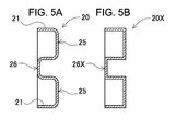
- FIG. 5A is a schematic vertical cross-sectional view of an end plate having a bead region formed in a curved surface
- FIG. 5B is a schematic cross-sectional view of an end plate having a bead region formed in a U shape
- 6A is a schematic vertical sectional view taken along the line VIA-VIA of FIG. 3, and FIG.
- FIG. 6B is a schematic vertical sectional view taken along the line VIB-VIB of FIG.
- FIG. 5 is a vertical cross-sectional view of an end plate portion of the power supply device according to the second embodiment.
- FIG. 5 is a vertical cross-sectional view of an end plate portion of the power supply device according to the third embodiment.
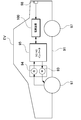
- It is a block diagram which shows an example which mounts a power supply device in a hybrid vehicle which runs by an engine and a motor.
- It is a block diagram which shows the example which mounts the power-source device on the electric vehicle which runs only by a motor.
- It is a block diagram which shows the example which applies to the power supply device for electricity storage.
- It is an exploded perspective view which shows the conventional power supply device.
- FIG. 5 is an exploded perspective view of an end plate portion of the power supply device according to the fourth embodiment.
- the embodiment of the present invention may be specified by the following configuration.
- the end plate forms side walls on both sides of the side surface of the pressing surface, and the side walls are on the edge side in the vertical direction.
- Each of the positions corresponding to the pressing region has a fixing region for fixing to the fastening member, and is connected to the protruding shape of the bead region at the central portion in the vertical direction.
- the end plate forms a curved surface with a protruding shape of the bead region.
- the side wall of the end plate is formed so as to be continuously connected to the bead region by a curved surface at a central portion. ..
- the central portion can be continuous with the protruding portion of the bead region to ensure strength.
- the end plate in addition to any of the above configurations, steeply protrudes the protruding shape of the bead region at the left and right central portions in a vertical cross-sectional view. It is gently tilted toward both sides.
- the central portion is brought closer to the ridge to improve the strength, and at the end portion, the side wall of the end plate secures the fixing portion with the fastening member.
- the end plate is formed by bending one metal plate by press working. With the above configuration, it is possible to reduce the cost and weight of the end plate.
- the end plate in addition to any of the above configurations, has a sum of the heights of the pressing regions formed at the top and bottom in a cross-sectional view. It is made equal to the height of the bead region formed in the middle.
- the end plate is fixed to the fastening member by welding or caulking.
- the electric vehicle includes any of the above power supply devices, a traveling motor to which power is supplied from the power supply device, the power supply device, and the motor. It includes a main body and wheels driven by the motor to drive the vehicle main body.
- the power storage device includes any of the above power supply devices and a power supply controller that controls charging / discharging to the power supply device, and the power supply controller is used to generate electric power from the outside. Allows the battery cell to be charged and controls the battery cell to be charged.
- each element constituting the present invention may be configured such that a plurality of elements are composed of the same member and the plurality of elements are combined with one member, or conversely, the function of one member is performed by the plurality of members. It can also be shared and realized.
- the contents described in some examples and embodiments can be used in other embodiments and embodiments.
- the power supply device is a power source mounted on an electric vehicle such as a hybrid vehicle or an electric vehicle to supply electric power to a traveling motor, a power source for storing electric power generated by natural energy such as solar power generation or wind power generation, or a power source for storing electric power generated by natural energy such as solar power generation and wind power generation. It is used for various purposes such as a power source for storing midnight power, and is particularly suitable as a power source suitable for high power and large current applications.
- a power source for storing midnight power and is particularly suitable as a power source suitable for high power and large current applications.
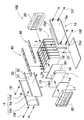
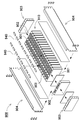
- FIGS. 1 to 2 show an exploded perspective view of the power supply device 100 shown in FIG.
- the power supply device 100 shown in these figures includes a battery laminate 10 in which a plurality of battery cells 1 are laminated via an insulating spacer 16, a pair of end plates 20 covering both end faces of the battery laminate 10, and an end plate 20. It includes a plurality of fastening members 15 for fastening each other, and a bus bar 40 provided on the upper surface of the battery laminate 10.
- the fastening member 15 is formed in a plate shape extending along the stacking direction of the plurality of battery cells 1.
- the fastening members 15 are arranged on opposite side surfaces of the battery laminate 10 to fasten the end plates 20 to each other. (Battery laminate 10)
- the battery laminate 10 is connected to a plurality of battery cells 1 having positive and negative electrode terminals 2 and electrode terminals 2 of the plurality of battery cells 1, and the plurality of battery cells 1 are arranged in parallel.
- a bus bar 40 connected in series is provided.
- a plurality of battery cells 1 are connected in parallel or in series via these bus bars 40.
- the battery cell 1 is a rechargeable secondary battery.
- a plurality of battery cells 1 are connected in parallel to form a parallel battery group, and a plurality of parallel battery groups are connected in series to connect a large number of battery cells 1 in parallel and in series.
- a plurality of battery cells 1 are laminated to form a battery laminate 10.
- a pair of end plates 20 are arranged on both end faces of the battery laminate 10. The ends of the fastening members 15 are fixed to the end plates 20, and the stacked battery cells 1 are fixed in a pressed state.
- the battery cell 1 is a square battery having a width wider than the thickness, in other words, a square battery thinner than the width, and is laminated in the thickness direction to form a battery laminate 10.
- the battery cell 1 can be, for example, a lithium ion secondary battery. Further, the battery cell can be any rechargeable secondary battery such as a nickel hydrogen battery or a nickel cadmium battery.
- positive and negative electrode plates are housed together with an electrolytic solution in an outer can 1a having a closed structure.
- a metal plate such as aluminum or an aluminum alloy is press-molded into a square shape, and the opening portion is airtightly sealed with a sealing plate 1b.
- the sealing plate 1b is made of the same aluminum or aluminum alloy as the square outer can 1a, and positive and negative electrode terminals 2 are fixed to both ends. Further, the sealing plate 1b is provided with a gas discharge valve 1c, which is a safety valve that opens according to a pressure change inside each of the battery cells 1, between the positive and negative electrode terminals 2.
- the plurality of battery cells 1 are laminated so that the thickness direction of each battery cell 1 is the stacking direction to form the battery laminate 10. At this time, the output of the battery laminate 10 can be increased by increasing the number of layers to be larger than usual. In such a case, the battery laminate 10 becomes a long one extended in the stacking direction.
- terminal surfaces 1X provided with positive and negative electrode terminals 2 are arranged on the same plane, and a plurality of battery cells 1 are laminated to form a battery laminate 10.
- the upper surface of the battery laminate 10 is a surface provided with gas discharge valves 1c of a plurality of battery cells 1. (Electrode terminal 2)
- the battery cell 1 has a sealing plate 1b, which is the top surface, as a terminal surface 1X, and positive and negative electrode terminals 2 are fixed to both ends of the terminal surface 1X.
- the electrode terminal 2 has a columnar protrusion.
- the protruding portion does not necessarily have to be cylindrical, and may be polygonal or elliptical.
- the positions of the positive and negative electrode terminals 2 fixed to the sealing plate 1b of the battery cell 1 are such that the positive electrode and the negative electrode are symmetrical.
- the battery cells 1 are flipped horizontally and stacked, and the electrode terminals 2 of the positive electrode and the negative electrode that are adjacent to each other are connected by the bus bar 40, whereby the adjacent battery cells 1 are connected in series. It is possible to connect to.
- the present invention does not specify the number of battery cells constituting the battery laminate and the connection state thereof.
- the number of battery cells constituting the battery laminate and the connection state thereof can be variously changed, including other embodiments described later.
- the plurality of battery cells 1 are laminated so that the thickness direction of each battery cell 1 is the stacking direction to form the battery laminate 10.
- a plurality of battery cells 1 are laminated so that the terminal surface 1X provided with the positive and negative electrode terminals 2 and the sealing plate 1b in FIG. 2 are flush with each other.
- adjacent electrode terminals 2 are connected by a metal plate bus bar 40, and battery cells 1 are connected in series. (Busbar 40)
- Both ends of the bus bar 40 are connected to positive and negative electrode terminals 2, and battery cells 1 are connected in series or in parallel.
- the battery cells 1 can be connected in series to increase the output voltage, and the battery cells 1 can be connected in parallel to increase the output voltage and output current.
- the battery laminate 10 has an insulating spacer 16 interposed between the battery cells 1 stacked adjacent to each other.
- the insulating spacer 16 is made of an insulating material such as resin in the form of a thin plate or sheet.
- the insulating spacer 16 has a plate shape having a size substantially equal to that of the facing surface of the battery cell 1.
- the insulating spacers 16 can be laminated between the battery cells 1 adjacent to each other to insulate the adjacent battery cells 1 from each other.
- a spacer having a shape in which a flow path of a cooling gas is formed between the battery cells and the spacer can also be used.
- the surface of the battery cell can be covered with an insulating material.
- the surface of the outer excluding the electrode terminal portion of the battery cell may be covered with a shrink film such as PET resin.
- end plates 20 are arranged on both end surfaces of the battery laminate 10.
- An end face spacer 17 may be interposed between the end plate 20 and the battery laminate 10 to insulate them.
- the end face spacer 17 can also be manufactured in the form of a thin plate or sheet with an insulating material such as resin.
- electrode terminals 2 of a plurality of battery cells 1 adjacent to each other are connected to each other by a bus bar 40 to form a plurality of batteries.
- the cells 1 are connected in parallel and in series.
- the end plates 20 are arranged at both ends of the battery laminate 10 and are fastened via a pair of left and right fastening members 15 arranged along both side surfaces of the battery laminate 10.
- the end plates 20 are both ends of the battery laminate 10 in the stacking direction of the battery cells 1, and are arranged outside the end face spacer 17 to sandwich the battery laminate 10 from both ends. (Fastening member 15)
- each fastening member 15 is made of metal having a predetermined width and a predetermined thickness along the side surface of the battery laminate 10, and is arranged so as to face both side surfaces of the battery laminate 10. There is.
- a metal plate such as iron, preferably a steel plate, can be used for the fastening member 15.
- the fastening member 15 made of a metal plate is bent by press molding or the like to form a predetermined shape.
- the fastening member 15 is formed by bending the upper and lower sides of the plate-shaped fastening main surface 15a in a U-shape to form a bent piece 15d.
- the upper and lower bent pieces 15d cover the upper and lower surfaces of the battery laminate 10 from the corners on the left and right side surfaces of the battery laminate 10.
- a plurality of battery cells 1 are connected by connecting end plates 20 arranged at both ends of a battery laminate 10 composed of the plurality of battery cells 1 with fastening members 15. Is configured to constrain. By restraining the plurality of battery cells 1 via the end plate 20 and the fastening member 15 having high rigidity, it is possible to suppress expansion, deformation, relative movement, malfunction due to vibration, etc. of the battery cells 1 due to charge / discharge and deterioration. .. (Insulation sheet 30)
- an insulating sheet 30 is interposed between the fastening member 15 and the battery laminate 10.
- the insulating sheet 30 is made of an insulating material such as resin, and insulates between the metal fastening member 15 and the battery cell 1.
- the insulating sheet 30 shown in FIG. 2 and the like is composed of a flat plate 31 that covers the side surface of the battery laminate 10 and bent covering portions 32 provided above and below the flat plate 31.
- the bent covering portion 32 is bent in a U shape from the flat plate 31 so as to cover the bent piece 15d of the fastening member 15, and then further folded back.
- the bent piece 15d can be covered with an insulating bent covering portion from the upper surface to the side surface and the lower surface, thereby avoiding unintended conduction between the battery cell 1 and the fastening member 15.
- each battery cell 1 presses the upper surface and the lower surface of the battery cell 1 of the battery laminate 10 via the bent covering portion 32.
- each battery cell 1 is pressed from the vertical direction by the bent piece 15d and held in the height direction, and even if vibration, impact, or the like is applied to the battery laminate 10, each battery cell 1 is positioned in the vertical direction. It can be maintained so that it does not shift.
- the battery cell When the surface of the battery laminate or the battery laminate is insulated, for example, the battery cell is housed in an insulating case, covered with a heat-shrinkable resin film, or the fastening member. If the surface is coated with an insulating paint or coating, or if the fastening member is made of an insulating material, the insulating sheet can be unnecessary. Further, the insulating sheet 30 may also have the bent covering portion 32 formed only on the upper end side when it is not necessary to consider the insulation of the fastening member 15 with the bent piece 15d on the lower surface side of the battery laminate 10. For example, the case where the battery cell is covered with a heat-shrinkable film is applicable. (End plate 20)
- FIG. 3 shows an enlarged perspective view of the end plate 20 portion of the power supply device 100 of FIG. 1
- FIG. 4 shows a vertical cross-sectional view of the end plate 20 portion of the power supply device 100 of FIG.
- the end plate 20 shown in these figures is formed in a frame shape 21 having a rectangular outer shape in a plan view and a protruding periphery. Further, the rectangular region surrounded by the frame shape 21 is used as a pressing surface covering the end surface of the battery laminate 10. By forming the box shape in which the frame shape 21 is formed around the pressing surface in this way, the strength of the pressing surface can be increased.
- screw holes or notches for connecting to other parts may be formed on the upper surface side of the frame-shaped 21.
- the end plate 20 forms a pressing region 25 on each of the vertical end edges of the pressing surface, and a bead region 26 is formed between the pressing regions 25. (Pressing area 25)
- the upper and lower pressing regions 25 each have a flat surface, and press the battery laminate 10.
- the widths of the upper and lower pressing regions 25 are substantially equal.
- the pressing region 25, including the bead region 26, is preferably formed line-symmetrically in the horizontal direction. (Bead area 26)
- the bead region 26 is formed in the middle of the pressing surface in the vertical direction, and is bent into a shape protruding toward the back surface side of the pressing surface.
- the strength can be improved by changing the shape of forming the bead region 26 in the middle while leaving the pressing region 25 for pressing the battery laminate 10 on the end plate 20, so that the high-strength end plate 20 can be improved.
- the end plate 20 When the end plate 20 is formed of sheet metal, the end plate 20 having a bead region 26 has a shape having a space on the battery cell 1 side. Therefore, it is preferable to arrange the end face spacer 17D arranged between the battery cell 1 and the end plate 20D as in the power supply device 400 according to the fourth embodiment shown in FIG. Specifically, as shown in FIG. 13, the end face spacer 17D has a convex portion 17d protruding toward a concave portion (back surface of the bead region 26D) of the end plate 20D, and the battery cell 1 and the end plate 20D. Allows the transfer of power on the entire surface. (Wall 22)
- the end plate 20 has a frame shape 21 around the pressing surface. Of the frame shape 21, both sides of the side surface of the pressing surface are side walls 22 respectively.
- the side wall 22 has a fixing region 23 for fixing to the fastening member 15 at a position corresponding to the pressing region 25 on the edge side in the vertical direction.
- the fixed region 23 is formed in the same plane at the top and bottom.
- the fixed region 23 is a flat surface.
- the end plate 20 is fixed to the fastening member 15 by the fixing region 23. Welding or caulking is preferable for fixing the end plate 20 and the fastening member 15. For example, spot welding, clinch, etc. can be used. Further, it may be screwed using a bolt or the like.
- the side wall 22 is connected to the protruding shape of the bead region 26 between these fixed regions 23, that is, at the central portion in the vertical direction.
- a fixed region 23 for connecting to the fastening member 15 is not provided in the middle of the side wall 22 in the height direction.
- the protruding shape of the bead region 26 is maintained and the reinforcing structure of the end plate 20 is exhibited.
- a fixing structure for fixing the end plate 20 to the fastening member 15 is also established by securing a fixing region 23 for fixing the fastening member 15 above and below the side wall 22.
- the protruding shape of the bead region 26 is preferably formed into a curved surface as shown in the schematic cross-sectional view of FIG. 5A.
- stress concentration can be avoided as compared with the end plate 20X having the bead region 26X bent in a U shape as shown in FIG. 5B, and the stress can be dispersed to increase the strength of the end plate 20. Can be improved.
- the side wall 22 of the end plate 20 is formed so as to be continuously connected to the bead region 26 by a curved surface at the center in the vertical direction.
- the central portion can be made continuous with the protruding portion of the bead region 26 to secure the strength.
- the protruding shape of the bead region 26 is projected relatively steeply in the central portions on the left and right as shown in FIG. 6A, but is gently inclined toward both sides as shown in FIG. 6B. It is preferable to form in. By doing so, in the middle of the pressing surface in the left-right direction where the strength is relatively weak, the protruding shape is made tight to increase the strength, and at the end of the pressing surface, the fastening member 15 is attached to the side wall 22 of the end plate 20. It can be deformed to secure a fixed area 23 for fixing the.
- the end plate 20 continuously forms the pressing region 25 and the bead region 26 on the pressing surface, but at the boundary with the side wall 22, the side wall 22 is slightly projected in the protruding direction, that is, pressed, as shown in FIG. It is preferable to incline in the direction toward the back surface side of the surface.
- Such an end plate 20 can be formed by bending one metal plate by press working. As a result, unlike the conventional end plate, it is possible to maintain the required strength while using only one sheet metal without using two sheets, and further realize cost reduction and weight reduction.
- the end plate 20 is preferably formed by processing a sheet metal such as SUS or a high-tensile steel plate.
- the size of the power supply device is increased in order to avoid interference between the equipment for fixing processing such as mechanical clinch and the power supply device as in the conventional case. There is no need.
- the end plate 20 is designed so that the sum of the heights of the pressing regions 25 formed at the top and bottom is substantially equal to the height of the bead region 26 formed in the middle in the cross-sectional view.
- the height of the upper pressing region 25 is b1
- the height of the bead region 26 is a
- the height of the lower pressing region 25 is b2.
- one bead region 26 is provided in the center of the end plate 20 in the vertical direction, but the present invention does not limit the number of bead regions to one, and a plurality of beads.
- a region may be provided.
- the power supply device 200 according to the second embodiment shown in the schematic cross-sectional view of FIG. 7 a configuration in which two bead regions 26B are provided on the end plate 20B is shown. By providing a plurality of bead regions 26B in this way, the strength of the end plate 20B can be further increased. Further, the pressing regions 25B are also dispersed and arranged in three, and the end faces of the battery laminate 10 can be pressed more uniformly.
- the fixing region 23B can be provided not only at the upper and lower edge edges but also in the middle, and the reliability of fixing the end plate 20B and the fastening member 15 can be improved.
- the same members as those in the first embodiment are designated by the same reference numerals, and detailed description thereof will be omitted as appropriate.
- the present invention is not limited to the example in which the bead region of the end plate is hollow, and can also be solid.
- Such an example is shown in the schematic cross-sectional view of FIG. 8 as the power supply device 300 according to the third embodiment.
- the same members as those in the first embodiment are designated by the same reference numerals, and detailed description thereof will be omitted as appropriate.
- the end plate 20C shown in FIG. 8 has a solid pressing surface without being hollow.
- the bead region 26 of the end plate 20C is filled with an insulating member 28 such as resin or rubber.
- the insulating member 28 may be configured to cover not only the bead region 26C but also the pressing region 25C.
- the pressing surface for pressing the battery laminate 10 can be made of a uniform material, the end surface of the battery laminate 10 can be pressed evenly, and heat can be dissipated evenly.
- the heat dissipation of the end face of the battery laminate 10 can be improved by eliminating the air layer as compared with the configuration shown in FIG. 4 in which the air layer is partially formed.
- the heat-bonded state with the end face of the battery laminate 10 can be made uniform to exhibit uniform heat dissipation performance.
- the power supply device 100 can be used as a power supply for a vehicle that supplies electric power to a motor that runs an electric vehicle.
- a vehicle equipped with the power supply device 100 an electric vehicle such as a hybrid vehicle or a plug-in hybrid vehicle that runs on both an engine and a motor, or an electric vehicle that runs only on a motor can be used, and is used as a power source for these vehicles. Will be done.
- a large number of the above-mentioned power supply devices 100 are connected in series or in parallel, and a large-capacity, high-output power supply device to which a necessary control circuit is added is constructed. do. (Power supply for hybrid vehicles)
- FIG. 9 shows an example in which the power supply device 100 is mounted on a hybrid vehicle traveling by both an engine and a motor.
- the vehicle HV equipped with the power supply device 100 shown in this figure is driven by a vehicle main body 91, an engine 96 for running the vehicle main body 91, a running motor 93, and these engines 96 and a running motor 93. It includes wheels 97, a power supply device 100 that supplies electric power to the motor 93, and a generator 94 that charges the batteries of the power supply device 100.
- the power supply device 100 is connected to the motor 93 and the generator 94 via the DC / AC inverter 95.
- the vehicle HV runs on both the motor 93 and the engine 96 while charging and discharging the battery of the power supply device 100.
- the motor 93 is driven to drive the vehicle in a region where the engine efficiency is low, for example, when accelerating or traveling at a low speed.
- the motor 93 is driven by being supplied with electric power from the power supply device 100.
- the generator 94 is driven by the engine 96 or by regenerative braking when braking the vehicle to charge the battery of the power supply device 100.
- the vehicle HV may be provided with a charging plug 98 for charging the power supply device 100. By connecting the charging plug 98 to an external power source, the power supply device 100 can be charged. (Power supply for electric vehicles)
- FIG. 10 shows an example in which the power supply device 100 is mounted on an electric vehicle traveling only by a motor.
- the vehicle EV equipped with the power supply device 100 shown in this figure supplies electric power to the vehicle main body 91, the traveling motor 93 for running the vehicle main body 91, the wheels 97 driven by the motor 93, and the motor 93.
- It includes a power supply device 100 for supplying power and a generator 94 for charging the battery of the power supply device 100.
- the power supply device 100 is connected to the motor 93 and the generator 94 via the DC / AC inverter 95.
- the motor 93 is driven by being supplied with electric power from the power supply device 100.
- the generator 94 is driven by the energy used for regenerative braking of the vehicle EV to charge the battery of the power supply device 100. Further, the vehicle EV is provided with a charging plug 98, and the charging plug 98 can be connected to an external power source to charge the power supply device 100. (Power supply device for power storage device)
- the present invention does not specify the use of the power supply device as the power supply of the motor that runs the vehicle.
- the power supply device according to the embodiment can also be used as a power source for a power storage device that charges and stores a battery with electric power generated by solar power generation, wind power generation, or the like.
- FIG. 11 shows a power storage device in which the battery of the power supply device 100 is charged by the solar cell 82 to store electricity.
- the power storage device shown in FIG. 11 charges the battery of the power supply device 100 with the electric power generated by the solar cell 82 arranged on the roof or roof of a building 81 such as a house or factory.
- This power storage device uses the solar cell 82 as a power source for charging, charges the battery of the power supply device 100 with the charging circuit 83, and then supplies power to the load 86 via the DC / AC inverter 85. Therefore, this power storage device has a charge mode and a discharge mode.
- the DC / AC inverter 85 and the charging circuit 83 are connected to the power supply device 100 via the discharge switch 87 and the charging switch 84, respectively.
- the ON / OFF of the discharge switch 87 and the charge switch 84 is switched by the power controller 88 of the power storage device.
- the power controller 88 switches the charging switch 84 to ON and the discharge switch 87 to OFF to allow the charging circuit 83 to charge the power supply device 100.
- the power controller 88 turns off the charging switch 84 and turns on the discharge switch 87 to switch to the discharge mode, and the power supply device 100 Allows discharge from to load 86.
- the charge switch 84 can be turned on and the discharge switch 87 can be turned on to supply power to the load 86 and charge the power supply device 100 at the same time.
- the power supply device can also be used as a power source for a power storage device that charges and stores batteries using midnight power at night.
- a power supply device charged with midnight power can be charged with midnight power, which is surplus power of a power plant, and output power in the daytime when the power load is large, so that the peak power in the daytime can be limited to a small value.
- the power supply can also be used as a power source for charging with both solar cell output and midnight power. This power supply device can effectively utilize both the power generated by the solar cell and the midnight power, and can efficiently store electricity while considering the weather and power consumption.
- the above-mentioned power storage system includes a backup power supply device that can be mounted in a computer server rack, a backup power supply device for a wireless base station such as a mobile phone, a power storage power supply for home or factory use, a power supply for street lights, and the like. It can be suitably used for power storage devices combined with solar cells, backup power sources for traffic lights and road traffic indicators, and the like.
- the power supply device is used as a power source for a large current used as a power source for a motor for driving an electric vehicle such as a hybrid vehicle, a fuel cell vehicle, an electric vehicle, or an electric motorcycle. It can be preferably used.
- a power supply device for a plug-in type hybrid electric vehicle, a hybrid type electric vehicle, an electric vehicle, or the like that can switch between an EV driving mode and a HEV driving mode can be mentioned.
- a backup power supply that can be mounted in a computer server rack, a backup power supply for wireless base stations such as mobile phones, a power storage device for home use and factories, a power supply for street lights, etc. , Can also be used as appropriate for backup power supplies such as traffic lights.
- Electrode terminal 10 ... Battery laminate 15 ... Fastening member; 15a ... Fastening Main surface; 15d ... Bent piece 15f ... Bolt 16 ... Insulating spacer 17, 17D ... End face spacer 17d ... Convex portion 20, 20B, 20C, 20D, 20X ... End plate 21 ... Frame shape 22 ... Side wall 23, 23B ... Fixed area 25, 25B, 25C ... Pressing area 26, 26B, 26C, 26D, 26X ... Bead area 28 ... Insulating member 30 ... Insulating sheet; 31 ...
Landscapes
- Chemical & Material Sciences (AREA)
- General Chemical & Material Sciences (AREA)
- Chemical Kinetics & Catalysis (AREA)
- Electrochemistry (AREA)
- Engineering & Computer Science (AREA)
- Mechanical Engineering (AREA)
- Transportation (AREA)
- Inorganic Chemistry (AREA)
- Aviation & Aerospace Engineering (AREA)
- Combustion & Propulsion (AREA)
- Manufacturing & Machinery (AREA)
- Life Sciences & Earth Sciences (AREA)
- Sustainable Development (AREA)
- Sustainable Energy (AREA)
- Power Engineering (AREA)
- Battery Mounting, Suspending (AREA)
- Electric Propulsion And Braking For Vehicles (AREA)
Abstract
電源装置(100)は、角形の電池セル(1)を複数積層した電池積層体(10)と、電池積層体(10)の端面を覆う押圧面を有する平面視矩形状のエンドプレート(20)と、電池積層体(10)を締結する締結部材(15)とを備える。エンドプレート(20)は、押圧面に、上下方向の端縁側にそれぞれ形成された、平坦な押圧領域(25)と、上下方向の中間側に形成された、該押圧面の背面側に突出する形状に折曲されたビード領域(26)とを形成している。これにより、エンドプレート(20)に電池積層体(10)を押圧する押圧領域(25)を残しつつも、中間にビード領域(26)を形成するという形状の変更によって強度を向上できるので、高強度のエンドプレート(20)を安価に提供できる。
Description
本開示は、電源装置及びこれを備える車両並びに蓄電装置に関する。
複数の電池セルを備える電池モジュールや電池パックなどの電源装置は、ハイブリッド自動車や電気自動車など車両用の電源や、工場用、家庭用などの蓄電システムの電源などに利用されている。
このような電源装置は、充放電可能な複数の電池セルを複数枚積層している。例えば図12の模式断面図に示すように、電源装置900は角型の外装缶の電池セル901を積層した電池積層体910の両側の端面に、それぞれエンドプレート903を配置し、エンドプレート903同士をバインドバー904で締結している。また角形の電池セル901は、その上面に正負の電極端子902を離間して設けている。隣接する電池セル901の電極端子902は、バスバー940で接続される。
このようにエンドプレートで電池積層体を押圧、締結する構造においては、エンドプレートに十分な強度を持たせる必要がある。一般にエンドプレートの強度を高めようとすると、コストが高くなる。例えば強度確保のために板金を2枚用いるエンドプレートは、高コストとなっていた。またエンドプレートとバインドバーの固定に際してメカニカルクリンチを用いる場合(特許文献1参照)、メカニカルクリンチは設備サイズが大きく、電源装置側で加工時の干渉を避ける必要が生じ、結果的に電源装置のサイズが大きくなるという問題もあった。
本発明の一態様に係る目的の一は、エンドプレートの強度を維持しつつも低コスト化を図った電源装置及びこれを備える車両並びに蓄電装置を提供することにある。
本発明のある態様に係る電源装置は、角形の電池セルを複数積層した電池積層体と、前記電池積層体の端面を覆う押圧面を有する平面視矩形状のエンドプレートと、前記電池積層体を締結する締結部材と、を備え、前記エンドプレートは、前記押圧面に、上下方向の端縁側にそれぞれ形成された、平坦な押圧領域と、上下方向の中間側に形成された、該押圧面の背面側に突出する形状に折曲されたビード領域とを形成している。
本発明のある態様に係る電源装置によれば、エンドプレートに電池積層体を押圧する押圧領域を残しつつも、中間にビード領域を形成するという形状の変更によって強度を向上できるので、高強度のエンドプレートを安価に提供できる。
本発明の実施形態は、以下の構成によって特定されてもよい。
本発明の一実施形態に係る電源装置は、上記構成に加えて、前記エンドプレートが、前記押圧面の側面の両側にそれぞれ側壁を形成しており、前記側壁は、上下方向の端縁側で、前記押圧領域と対応する位置にそれぞれ、前記締結部材と固定するための固定領域を有しており、上下方向の中央部分で、前記ビード領域の突出形状と接続している。上記構成により、エンドプレートを締結部材と連結させる固定領域をエンドプレート両側側面に確保しつつも、中央部分はビード領域の突出形状と連続させて強度を確保できる。
本発明の他の実施形態に係る電源装置は、上記いずれかの構成に加えて、前記エンドプレートが、前記ビード領域の突出形状を曲面状に形成している。上記構成により、ビード領域をコ字状に折曲させた構成と比べて応力の集中を避けることができ、応力の分散を図ってエンドプレートの強度を向上させることが可能となる。
また、本発明の他の実施形態に係る電源装置は、上記いずれかの構成に加えて、前記エンドプレートの側壁が、中央部分で前記ビード領域と連続的に曲面で連なるように形成されている。上記構成により、エンドプレートを締結部材と連結させる領域をエンドプレートの側壁に確保しつつも、中央部分はビード領域の突出部分と連続させて強度を確保できる。
さらに、本発明の他の実施形態に係る電源装置は、上記いずれかの構成に加えて、前記エンドプレートが、前記ビード領域の突出形状を、垂直断面視において、左右の中央部分で急峻に突出させて、両側に向かうにつれてなだらかに傾斜させている。上記構成により、中央部分は凸条に近付けて強度を向上させつつ、端部ではエンドプレートの側壁で締結部材との固定部分を確保している。
さらにまた、本発明の他の実施形態に係る電源装置は、上記いずれかの構成に加えて、前記エンドプレートが、1枚の金属板をプレス加工で折曲して形成されている。上記構成により、エンドプレートの低コスト化と軽量化を図ることが可能となる。
さらにまた、本発明の他の実施形態に係る電源装置は、上記いずれかの構成に加えて、前記エンドプレートは、断面視において、上下にそれぞれ形成された前記押圧領域の高さの和を、中間に形成されたビード領域の高さと同等にしている。上記構成により、エンドプレートの押圧力と剛性をバランスよく両立させることが可能となる。
さらにまた、本発明の他の実施形態に係る電源装置は、上記いずれかの構成に加えて、前記エンドプレートが、前記締結部材と溶接またはかしめにより固定されている。上記構成により、エンドプレートに締結部材との固定部分を確保しつつも強度アップを図ることが可能となる。
さらにまた、本発明の他の実施形態に係る電動車両は、上記何れかの電源装置と、該電源装置から電力供給される走行用のモータと、前記電源装置及び前記モータを搭載してなる車両本体と、前記モータで駆動されて前記車両本体を走行させる車輪とを備える。
さらにまた、本発明の他の実施形態に係る蓄電装置は、上記何れかの電源装置と、該電源装置への充放電を制御する電源コントローラと備えて、前記電源コントローラでもって、外部からの電力により前記電池セルへの充電を可能とすると共に、該電池セルに対し充電を行うよう制御する。
以下、本発明の実施形態を図面に基づいて説明する。ただし、以下に示す実施形態は、本発明の技術思想を具体化するための例示であって、本発明は以下のものに特定されない。また、本明細書は、特許請求の範囲に示される部材を、実施形態の部材に特定するものでは決してない。特に実施形態に記載されている構成部材の寸法、材質、形状、その相対的配置等は特に特定的な記載がない限りは、本発明の範囲をそれのみに限定する趣旨ではなく、単なる説明例にすぎない。なお、各図面が示す部材の大きさや位置関係等は、説明を明確にするため誇張していることがある。さらに以下の説明において、同一の名称、符号については同一もしくは同質の部材を示しており、詳細説明を適宜省略する。さらに、本発明を構成する各要素は、複数の要素を同一の部材で構成して一の部材で複数の要素を兼用する態様としてもよいし、逆に一の部材の機能を複数の部材で分担して実現することもできる。また、一部の実施例、実施形態において説明された内容は、他の実施例、実施形態等に利用可能なものもある。
実施形態に係る電源装置は、ハイブリッド車や電気自動車などの電動車両に搭載されて走行用モータに電力を供給する電源、太陽光発電や風力発電などの自然エネルギーの発電電力を蓄電する電源、あるいは深夜電力を蓄電する電源など、種々の用途に使用され、とくに大電力、大電流の用途に好適な電源として使用される。以下の例では、電動車両の駆動用の電源装置に適用した実施形態について、説明する。
[実施形態1]
[実施形態1]
本発明の実施形態1に係る電源装置100を、図1~図2にそれぞれ示す。これらの図において、図1は実施形態1に係る電源装置100の斜視図、図2は図1に示す電源装置100の分解斜視図を、それぞれ示している。これらの図に示す電源装置100は、複数の電池セル1を絶縁スペーサ16を介して積層した電池積層体10と、この電池積層体10の両側端面を覆う一対のエンドプレート20と、エンドプレート20同士を締結する複数の締結部材15と、電池積層体10の上面に設けられたバスバー40を備える。締結部材15は、複数の電池セル1の積層方向に沿って延長された板状に形成される。この締結部材15は、電池積層体10の対向する側面にそれぞれ配置されて、エンドプレート20同士を締結する。
(電池積層体10)
(電池積層体10)
電池積層体10は、図2に示すように、正負の電極端子2を備える複数の電池セル1と、これら複数の電池セル1の電極端子2に接続されて、複数の電池セル1を並列かつ直列に接続するバスバー40を備える。これらのバスバー40を介して複数の電池セル1を並列や直列に接続している。電池セル1は、充放電可能な二次電池である。電源装置100は、複数の電池セル1が並列に接続されて並列電池グループを構成すると共に、複数の並列電池グループが直列に接続されて、多数の電池セル1が並列かつ直列に接続される。図2に示す電源装置100は、複数の電池セル1を積層して電池積層体10を形成している。また電池積層体10の両端面には一対のエンドプレート20が配置される。このエンドプレート20同士に、締結部材15の端部を固定して、積層状態の電池セル1を押圧した状態に固定する。
(電池セル1)
(電池セル1)
電池セル1は、図2に示すように、厚さに比べて幅が広い、言い換えると幅よりも薄い角形電池で、厚さ方向に積層されて電池積層体10としている。電池セル1は、例えば、リチウムイオン二次電池とすることができる。また、電池セルは、ニッケル水素電池、ニッケルカドミウム電池等、充電できる全ての二次電池とすることもできる。電池セル1は、密閉構造の外装缶1aに正負の電極板を電解液と共に収容している。外装缶1aは、アルミニウムやアルミニウム合金等の金属板を角形にプレス成形され、開口部分を封口板1bで気密に密閉している。封口板1bは、角型の外装缶1aと同じアルミニウムやアルミニウム合金で、両端部に正負の電極端子2を固定している。さらに、封口板1bは、正負の電極端子2の間に、電池セル1のそれぞれ内部の圧力変化に応じて開弁する安全弁であるガス排出弁1cを設けている。
複数の電池セル1は、各電池セル1の厚み方向が積層方向となるように積層されて電池積層体10を構成している。この際、積層数を通常よりも多めにすることで、電池積層体10の高出力化を図ることができる。斯かる場合、電池積層体10は積層方向に延長された長尺のものとなる。電池セル1は、正負の電極端子2を設けている端子面1Xを同一平面に配置して、複数の電池セル1を積層して電池積層体10としている。そして、電池積層体10の上面を、複数の電池セル1のガス排出弁1cを設けた面としている。
(電極端子2)
(電極端子2)
電池セル1は、図2等に示すように天面である封口板1bを端子面1Xとして、この端子面1Xの両端部に正負の電極端子2を固定している。電極端子2は、突出部を円柱状としている。ただ、突出部は、必ずしも円柱状とする必要はなく、多角柱状又は楕円柱状とすることもできる。
電池セル1の封口板1bに固定される正負の電極端子2の位置は、正極と負極が左右対称となる位置としている。これにより、図2に示すように、電池セル1を左右反転させて積層し、隣接して接近する正極と負極の電極端子2をバスバー40で接続することで、隣接する電池セル1同士を直列に接続できるようにしている。なお、本発明は、電池積層体を構成する電池セルの個数とその接続状態を特定しない。後述する他の実施形態も含めて、電池積層体を構成する電池セルの個数、及びその接続状態を種々に変更することもできる。
複数の電池セル1は、各電池セル1の厚さ方向が積層方向となるように積層されて、電池積層体10を構成している。電池積層体10は、正負の電極端子2を設けている端子面1X、図2においては封口板1bが同一平面となるように、複数の電池セル1を積層している。また電池積層体10は、隣接する電極端子2を金属板のバスバー40で連結して、電池セル1を直列に接続している。
(バスバー40)
(バスバー40)
バスバー40は、その両端部を正負の電極端子2に接続して、電池セル1を直列に、あるいは並列に接続する。電源装置100は、電池セル1を直列に接続して出力電圧を高くし、電池セル1を直列と並列に接続して、出力電圧と出力電流を大きくできる。
(絶縁スペーサ16)
(絶縁スペーサ16)
電池積層体10は、隣接して積層される電池セル1同士の間に、絶縁スペーサ16を介在させている。絶縁スペーサ16は、樹脂等の絶縁材で薄いプレート状又はシート状に製作されている。絶縁スペーサ16は、電池セル1の対向面とほぼ等しい大きさのプレート状とする。この絶縁スペーサ16を互いに隣接する電池セル1の間に積層して、隣接する電池セル1同士を絶縁できる。なお、隣接する電池セル間に配置されるスペーサとしては、電池セルとスペーサの間に冷却気体の流路が形成される形状のスペーサを用いることもできる。また、電池セルの表面を絶縁材で被覆することもできる。例えばPET樹脂等のシュリンクフィルムで電池セルの電極端子部分を除く外装缶の表面を覆ってもよい。
さらに、図2に示す電源装置100は、電池積層体10の両端面にエンドプレート20を配置している。なおエンドプレート20と電池積層体10の間に端面スペーサ17を介在させて、これらを絶縁してもよい。端面スペーサ17も、樹脂等の絶縁材で薄いプレート状又はシート状に製作できる。
実施形態1に係る電源装置100は、複数の電池セル1が互いに積層される電池積層体10において、互いに隣接する複数の電池セル1の電極端子2同士をバスバー40で接続して、複数の電池セル1を並列かつ直列に接続する。
エンドプレート20は、図2に示すように、電池積層体10の両端に配置されると共に、電池積層体10の両側面に沿って配置される左右一対の締結部材15を介して締結される。エンドプレート20は、電池積層体10の電池セル1の積層方向における両端であって、端面スペーサ17の外側に配置されて電池積層体10を両端から挟着している。
(締結部材15)
(締結部材15)
締結部材15は、両端を電池積層体10の両端面に配置されたエンドプレート20に固定される。複数の締結部材15でもってエンドプレート20を固定し、もって電池積層体10を積層方向に締結している。各締結部材15は、図2等に示すように、電池積層体10の側面に沿う所定の幅と所定の厚さを有する金属製で、電池積層体10の両側面に対向して配置されている。この締結部材15には、鉄などの金属板、好ましくは、鋼板が使用できる。金属板からなる締結部材15は、プレス成形等により折曲加工されて所定の形状に形成される。
締結部材15は、板状の締結主面15aの上下をコ字状に折曲して、折曲片15dを形成している。上下の折曲片15dは、電池積層体10の左右側面において、電池積層体10の上下面を隅部から覆う。
多数の電池セル1を積層している電源装置100は、複数の電池セル1からなる電池積層体10の両端に配置されるエンドプレート20を締結部材15で連結することで、複数の電池セル1を拘束するように構成されている。複数の電池セル1を、高い剛性をもつエンドプレート20や締結部材15を介して拘束することで、充放電や劣化に伴う電池セル1の膨張、変形、相対移動、振動による誤動作などを抑制できる。
(絶縁シート30)
(絶縁シート30)
また締結部材15と電池積層体10の間には、絶縁シート30が介在される。絶縁シート30は絶縁性を備える材質、例えば樹脂などで構成され、金属製の締結部材15と電池セル1との間を絶縁している。図2等に示す絶縁シート30は、電池積層体10の側面を覆う平板31と、この平板31の上下にそれぞれ設けられた折曲被覆部32とで構成される。折曲被覆部32は、締結部材15の折曲片15dを覆うように、平板31からコ字状に折曲した後、さらに折り返している。これにより折曲片15dは、上面から側面及び下面にかけて絶縁性の折曲被覆部で覆うことにより、電池セル1と締結部材15の意図しない導通を回避することができる。
また折曲片15dは、折曲被覆部32を介して、電池積層体10の電池セル1の上面及び下面を押圧する。これにより、各電池セル1を上下方向から折曲片15dで押圧して高さ方向に保持し、振動や衝撃等が電池積層体10に印加されても、各電池セル1が上下方向に位置ずれしないように維持できる。
なお、電池積層体や電池積層体の表面が絶縁されている場合、例えば電池セルが絶縁性のケースに収納されていたり、樹脂製の熱収縮性フィルムで覆われている場合、又は締結部材の表面に絶縁性の塗料やコーティングが施されている場合、あるいは締結部材が絶縁性の材質で構成されている場合等は、絶縁シートを不要とできる。また絶縁シート30も、電池積層体10の下面側で締結部材15の折曲片15dとの絶縁を考慮しなくてよい場合は、折曲被覆部32を上端側にのみ形成してもよい。例えば電池セルを熱収縮性フィルムで被覆している場合等が該当する。
(エンドプレート20)
(エンドプレート20)
エンドプレート20の詳細を、図3~図4に基づいて説明する。これらの図において、図3は図1の電源装置100のエンドプレート20部分の拡大斜視図、図4は図1の電源装置100のエンドプレート20部分の垂直断面図を、それぞれ示している。これらの図に示すエンドプレート20は、平面視における外形を矩形状としつつ、周囲を突出させた枠状21に形成している。また枠状21で囲まれた矩形状の領域を、電池積層体10の端面を覆う押圧面としている。このように押圧面の周囲に枠状21を形成した箱形とすることで、押圧面の強度を増すことができる。枠状21の上面側には、必要に応じて他の部位と接続するためのネジ穴や切り欠きを形成してもよい。さらにエンドプレート20は、この押圧面の、上下方向の端縁側にそれぞれ押圧領域25を形成し、この押圧領域25の間にビード領域26を形成している。
(押圧領域25)
(押圧領域25)
上下の押圧領域25は、それぞれ平坦な面を有しており、電池積層体10を押圧する。好ましくは、上下の押圧領域25の幅はほぼ等しくする。また押圧領域25はビード領域26を含めて、水平方向に線対称に形成することが好ましい。
(ビード領域26)
(ビード領域26)
一方、ビード領域26は、押圧面の上下方向の中間に形成されており、この押圧面の背面側に突出する形状に折曲されている。このような構成により、エンドプレート20に電池積層体10を押圧する押圧領域25を残しつつも、中間にビード領域26を形成するという形状の変更によって強度を向上できるので、高強度のエンドプレート20を安価に提供できる。
エンドプレート20を板金で成形する場合、ビード領域26を有する形状のエンドプレート20は、電池セル1側に空間を有する形状となる。そのため、図13に示す実施形態4に係る電源装置400のように、電池セル1とエンドプレート20Dの間に配置される端面スペーサ17Dを配置することが好ましい。具体的には、図13に示すように、端面スペーサ17Dは、エンドプレート20Dの凹部(ビード領域26Dの裏面)に向かって突出する凸部17dを有しており、電池セル1とエンドプレート20Dが全面で力の受け渡しができるようにしている。
(側壁22)
(側壁22)
一方、エンドプレート20は、押圧面の周囲を枠状21に形成している。この枠状21の内、押圧面の側面の両側をそれぞれ側壁22としている。この側壁22は、上下方向の端縁側で、押圧領域25と対応する位置にそれぞれ、締結部材15と固定するための固定領域23を有している。固定領域23は、上下で同一平面状に形成される。また固定領域23は平坦面とする。このエンドプレート20は固定領域23でもって、締結部材15と固定される。エンドプレート20と締結部材15の固定には、溶接やかしめが好ましい。例えばスポット溶接やクリンチ等が利用できる。また、ボルト等を用いた螺合としてもよい。
また側壁22は、これら固定領域23の間、すなわち上下方向の中央部分で、ビード領域26の突出形状と接続している。いいかえると、側壁22の高さ方向の中間には、締結部材15と連結させる固定領域23を設けていない。このように、ビード領域26を図3等に示すように押圧面を水平方向に横切るように貫通させることで、ビード領域26の突出形状を維持して、エンドプレート20の補強構造を発揮させている。その一方で、側壁22の上下に、締結部材15と固定するための固定領域23を確保して、エンドプレート20を締結部材15に固定するための固定構造も確立している。
ビード領域26の突出形状は、図5Aの模式断面図に示すように、曲面状に形成することが好ましい。これにより、図5Bに示すようにビード領域26Xをコ字状に折曲させた構成のエンドプレート20Xと比べて応力の集中を避けることができ、応力の分散を図ってエンドプレート20の強度を向上させることができる。
またエンドプレート20の側壁22は、上下方向の中央でビード領域26と連続的に曲面で連なるように形成することが好ましい。これにより、エンドプレート20を締結部材15と連結させる領域をエンドプレート20の側壁22に確保しつつも、中央部分はビード領域26の突出部分と連続させて強度を確保できる。
さらにビード領域26の突出形状を、垂直断面視において、左右の中央部分では図6Aに示すように相対的に急峻に突出させつつも、図6Bに示すように両側に向かうにつれてなだらかに傾斜させるように形成することが好ましい。このようにすることで、相対的に強度が弱くなる押圧面の左右方向の中間において、突出形状をきつくして強度を高めつつ、押圧面の端部ではエンドプレート20の側壁22に締結部材15の固定するための固定領域23を確保するために変形させることができる。
加えてエンドプレート20は、押圧面においてこれら押圧領域25とビード領域26を連続的に形成しつつも、側壁22との境界においては、図3に示すように若干、側壁22の突出方向すなわち押圧面の背面側に向かう方向に傾斜させることが好ましい。このように加工することで、押圧面と側壁22との境界部分での応力集中も緩和することができ、押圧面と側壁22の境界部分が破損するリスクも低減できる。
このようなエンドプレート20は、1枚の金属板をプレス加工で折曲して形成できる。これにより、従来のエンドプレートのように板金を2枚用いることなく、1枚としながらも必要な強度を維持し、さらにコスト削減や軽量化も実現できる。エンドプレート20は、SUSやハイテン板などの板金を加工して構成することが好ましい。
またこの構成のエンドプレート20であれば、締結部材15に固定する際、従来のようにメカニカルクリンチ等の固定加工用の設備と電源装置との干渉を避けるために電源装置のサイズを大型化する必要もない。
さらにエンドプレート20は、断面視において、上下にそれぞれ形成された押圧領域25の高さの和を、中間に形成されたビード領域26の高さとほぼ等しく設計することが好ましい。例えばエンドプレート20の幅方向の中間における垂直断面図である図4において、上方の押圧領域25の高さをb1、ビード領域26の高さをa、下方の押圧領域25の高さをb2としたとき、a=b1+b2とすることが好ましい。このように設計することで、エンドプレート20の押圧力と剛性をバランスよく両立させることが可能となる。
[実施形態2]
[実施形態2]
以上の実施形態1では、エンドプレート20の上下方向の中央にビード領域26を一本設けた例を示したが、本発明はビード領域の数を一本に限定するものでなく、複数のビード領域を設けてもよい。一例として、図7の模式断面図に示す実施形態2に係る電源装置200では、エンドプレート20Bに2つのビード領域26Bを設けた構成を示している。このようにビード領域26Bを複数設けることで、さらにエンドプレート20Bの強度を増すことができる。また押圧領域25Bも3つに分散して配置され、より均一に電池積層体10の端面を押圧できる。さらにエンドプレート20Bの側壁22においても、固定領域23Bを上下の端縁のみならず中間にも設けることが可能となって、エンドプレート20Bと締結部材15の固定の信頼性も向上できる。なお実施形態2に係る電源装置200においては、上述した実施形態1と同様の部材については、同じ符号を付して詳細説明を適宜省略する。
[実施形態3]
[実施形態3]
また以上の例では、エンドプレートを折曲してビード領域を設けた状態で、その押圧面を電池積層体に押圧して締結する例を説明した。ただ本発明は、エンドプレートのビード領域を空洞とする例に限らず、中実とすることもできる。このような例を実施形態3に係る電源装置300として、図8の模式断面図に示す。なお実施形態3に係る電源装置300においても、上述した実施形態1と同様の部材については、同じ符号を付して詳細説明を適宜省略する。
図8に示すエンドプレート20Cは、押圧面を空洞とせず、中実としている。例えばエンドプレート20Cのビード領域26に、樹脂やゴム等の絶縁部材28を充填している。絶縁部材28は、ビード領域26Cのみならず、押圧領域25Cも被覆するように構成してもよい。これにより、電池積層体10を押圧する押圧面を均一な材質で構成して、電池積層体10の端面を均等に押圧し、また放熱も均等に行うことができる。また絶縁部材28を充填することで、部分的に空気層が形成される図4等の構成と比べ、空気層をなくして電池積層体10の端面の放熱性を向上できる。また電池積層体10の端面との熱結合状態を均一して、均等な放熱性能を発揮させることもできる。
以上のようにして、エンドプレートの低コスト化と軽量化を図ることが可能となる。また電源装置100は、電動車両を走行させるモータに電力を供給する車両用の電源として利用できる。電源装置100を搭載する電動車両としては、エンジンとモータの両方で走行するハイブリッド自動車やプラグインハイブリッド自動車、あるいはモータのみで走行する電気自動車等の電動車両が利用でき、これらの車両の電源として使用される。なお、電動車両を駆動する電力を得るために、上述した電源装置100を直列や並列に多数接続して、さらに必要な制御回路を付加した大容量、高出力の電源装置を構築した例として説明する。
(ハイブリッド車用電源装置)
(ハイブリッド車用電源装置)
図9は、エンジンとモータの両方で走行するハイブリッド自動車に電源装置100を搭載する例を示す。この図に示す電源装置100を搭載した車両HVは、車両本体91と、この車両本体91を走行させるエンジン96及び走行用のモータ93と、これらのエンジン96及び走行用のモータ93で駆動される車輪97と、モータ93に電力を供給する電源装置100と、電源装置100の電池を充電する発電機94とを備えている。電源装置100は、DC/ACインバータ95を介してモータ93と発電機94に接続している。車両HVは、電源装置100の電池を充放電しながらモータ93とエンジン96の両方で走行する。モータ93は、エンジン効率の悪い領域、例えば加速時や低速走行時に駆動されて車両を走行させる。モータ93は、電源装置100から電力が供給されて駆動する。発電機94は、エンジン96で駆動され、あるいは車両にブレーキをかけるときの回生制動で駆動されて、電源装置100の電池を充電する。なお、車両HVは、図9に示すように、電源装置100を充電するための充電プラグ98を備えてもよい。この充電プラグ98を外部電源と接続することで、電源装置100を充電できる。
(電気自動車用電源装置)
(電気自動車用電源装置)
また、図10は、モータのみで走行する電気自動車に電源装置100を搭載する例を示す。この図に示す電源装置100を搭載した車両EVは、車両本体91と、この車両本体91を走行させる走行用のモータ93と、このモータ93で駆動される車輪97と、このモータ93に電力を供給する電源装置100と、この電源装置100の電池を充電する発電機94とを備えている。電源装置100は、DC/ACインバータ95を介してモータ93と発電機94に接続している。モータ93は、電源装置100から電力が供給されて駆動する。発電機94は、車両EVを回生制動する時のエネルギーで駆動されて、電源装置100の電池を充電する。また車両EVは充電プラグ98を備えており、この充電プラグ98を外部電源と接続して電源装置100を充電できる。
(蓄電装置用の電源装置)
(蓄電装置用の電源装置)
さらに、本発明は、電源装置の用途を、車両を走行させるモータの電源には特定しない。実施形態に係る電源装置は、太陽光発電や風力発電等で発電された電力で電池を充電して蓄電する蓄電装置の電源として使用することもできる。図11は、電源装置100の電池を太陽電池82で充電して蓄電する蓄電装置を示す。
図11に示す蓄電装置は、家屋や工場等の建物81の屋根や屋上等に配置された太陽電池82で発電される電力で電源装置100の電池を充電する。この蓄電装置は、太陽電池82を充電用電源として充電回路83で電源装置100の電池を充電した後、DC/ACインバータ85を介して負荷86に電力を供給する。このため、この蓄電装置は、充電モードと放電モードを備えている。図に示す蓄電装置は、DC/ACインバータ85と充電回路83を、それぞれ放電スイッチ87と充電スイッチ84を介して電源装置100と接続している。放電スイッチ87と充電スイッチ84のON/OFFは、蓄電装置の電源コントローラ88によって切り替えられる。充電モードにおいては、電源コントローラ88は充電スイッチ84をONに、放電スイッチ87をOFFに切り替えて、充電回路83から電源装置100への充電を許可する。また、充電が完了し満充電になると、あるいは所定値以上の容量が充電された状態で、電源コントローラ88は充電スイッチ84をOFFに、放電スイッチ87をONにして放電モードに切り替え、電源装置100から負荷86への放電を許可する。また、必要に応じて、充電スイッチ84をONに、放電スイッチ87をONにして、負荷86への電力供給と、電源装置100への充電を同時に行うこともできる。
さらに、電源装置は、図示しないが、夜間の深夜電力を利用して電池を充電して蓄電する蓄電装置の電源として使用することもできる。深夜電力で充電される電源装置は、発電所の余剰電力である深夜電力で充電して、電力負荷の大きくなる昼間に電力を出力して、昼間のピーク電力を小さく制限することができる。さらに、電源装置は、太陽電池の出力と深夜電力の両方で充電する電源としても使用できる。この電源装置は、太陽電池で発電される電力と深夜電力の両方を有効に利用して、天候や消費電力を考慮しながら効率よく蓄電できる。
以上のような蓄電システムは、コンピュータサーバのラックに搭載可能なバックアップ電源装置、携帯電話等の無線基地局用のバックアップ電源装置、家庭内用または工場用の蓄電用電源、街路灯の電源等、太陽電池と組み合わせた蓄電装置、信号機や道路用の交通表示器などのバックアップ電源用などの用途に好適に利用できる。
本発明に係る電源装置及びこれを備える車両並びに蓄電装置は、ハイブリッド車、燃料電池自動車、電気自動車、電動オートバイ等の電動車両を駆動するモータの電源用等に使用される大電流用の電源として好適に利用できる。例えばEV走行モードとHEV走行モードとを切り替え可能なプラグイン式ハイブリッド電気自動車やハイブリッド式電気自動車、電気自動車等の電源装置が挙げられる。またコンピュータサーバのラックに搭載可能なバックアップ電源装置、携帯電話等の無線基地局用のバックアップ電源装置、家庭内用、工場用の蓄電用電源、街路灯の電源等、太陽電池と組み合わせた蓄電装置、信号機等のバックアップ電源用等の用途にも適宜利用できる。
100、200、300、400、900…電源装置
1…電池セル
1X…端子面
1a…外装缶
1b…封口板
1c…ガス排出弁
2…電極端子
10…電池積層体
15…締結部材;15a…締結主面;15d…折曲片
15f…ボルト
16…絶縁スペーサ
17、17D…端面スペーサ
17d…凸部
20、20B、20C、20D、20X…エンドプレート
21…枠状
22…側壁
23、23B…固定領域
25、25B、25C…押圧領域
26、26B、26C、26D、26X…ビード領域
28…絶縁部材
30…絶縁シート;31…平板;32…折曲被覆部
40…バスバー
81…建物
82…太陽電池
83…充電回路
84…充電スイッチ
85…DC/ACインバータ
86…負荷
87…放電スイッチ
88…電源コントローラ
91…車両本体
93…モータ
94…発電機
95…DC/ACインバータ
96…エンジン
97…車輪
98…充電プラグ
901…電池セル
902…電極端子
903…エンドプレート
904…バインドバー
910…電池積層体
940…バスバー
HV、EV…車両
1…電池セル
1X…端子面
1a…外装缶
1b…封口板
1c…ガス排出弁
2…電極端子
10…電池積層体
15…締結部材;15a…締結主面;15d…折曲片
15f…ボルト
16…絶縁スペーサ
17、17D…端面スペーサ
17d…凸部
20、20B、20C、20D、20X…エンドプレート
21…枠状
22…側壁
23、23B…固定領域
25、25B、25C…押圧領域
26、26B、26C、26D、26X…ビード領域
28…絶縁部材
30…絶縁シート;31…平板;32…折曲被覆部
40…バスバー
81…建物
82…太陽電池
83…充電回路
84…充電スイッチ
85…DC/ACインバータ
86…負荷
87…放電スイッチ
88…電源コントローラ
91…車両本体
93…モータ
94…発電機
95…DC/ACインバータ
96…エンジン
97…車輪
98…充電プラグ
901…電池セル
902…電極端子
903…エンドプレート
904…バインドバー
910…電池積層体
940…バスバー
HV、EV…車両
Claims (10)
- 角形の電池セルを複数積層した電池積層体と、
前記電池積層体の端面を覆う押圧面を有する平面視矩形状のエンドプレートと、
前記電池積層体を締結する締結部材と、
を備え、
前記エンドプレートは、前記押圧面に、
上下方向の端縁側にそれぞれ形成された、平坦な押圧領域と、
上下方向の中間側に形成された、該押圧面の背面側に突出する形状に折曲されたビード領域と、
を形成してなる電源装置。 - 請求項1に記載の電源装置であって、
前記エンドプレートが、前記押圧面の側面の両側にそれぞれ側壁を形成しており、
前記側壁は、
上下方向の端縁側で、前記押圧領域と対応する位置にそれぞれ、前記締結部材と固定するための固定領域を有しており、
上下方向の中央部分で、前記ビード領域の突出形状と接続してなる電源装置。 - 請求項1又は2に記載の電源装置であって、
前記エンドプレートが、前記ビード領域の突出形状を曲面状に形成してなる電源装置。 - 請求項3に記載の電源装置であって、
前記エンドプレートの側壁が、中央部分で前記ビード領域と連続的に曲面で連なるように形成されてなる電源装置。 - 請求項4に記載の電源装置であって、
前記エンドプレートが、前記ビード領域の突出形状を、垂直断面視において、左右の中央部分で急峻に突出させて、両側に向かうにつれてなだらかに傾斜させてなる電源装置。 - 請求項1~5のいずれか一項に記載の電源装置であって、
前記エンドプレートが、1枚の金属板をプレス加工で折曲して形成されてなる電源装置。 - 請求項1~6のいずれか一項に記載の電源装置であって、
前記エンドプレートは、断面視において、上下にそれぞれ形成された前記押圧領域の高さの和を、中間に形成されたビード領域の高さと同等にしてなる電源装置。 - 請求項1~7のいずれか一項に記載の電源装置であって、
前記エンドプレートが、前記締結部材と溶接またはかしめにより固定されてなる電源装置。 - 請求項1~8のいずれか一に記載の電源装置を備える車両であって、
前記電源装置と、該電源装置から電力供給される走行用のモータと、前記電源装置及び前記モータを搭載してなる車両本体と、前記モータで駆動されて前記車両本体を走行させる車輪とを備える車両。 - 請求項1~9のいずれか一に記載の電源装置を備える蓄電装置であって、
前記電源装置と、該電源装置への充放電を制御する電源コントローラとを備えており、前記電源コントローラでもって、外部からの電力により前記電池セルへの充電を可能とすると共に、該電池セルに対し充電を行うよう制御する蓄電装置。
Priority Applications (4)
| Application Number | Priority Date | Filing Date | Title |
|---|---|---|---|
| CN202080099005.8A CN115380423A (zh) | 2020-03-31 | 2020-11-25 | 电源装置和具备该电源装置的车辆以及蓄电装置 |
| US17/906,291 US20230098629A1 (en) | 2020-03-31 | 2020-11-25 | Power supply device, vehicle provided with same, and power storage device |
| JP2022511518A JP7649294B2 (ja) | 2020-03-31 | 2020-11-25 | 電源装置及びこれを備える車両並びに蓄電装置 |
| EP20928244.1A EP4131561A4 (en) | 2020-03-31 | 2020-11-25 | POWER SUPPLY DEVICE, VEHICLE INCLUDING SAME, AND ENERGY STORAGE DEVICE |
Applications Claiming Priority (2)
| Application Number | Priority Date | Filing Date | Title |
|---|---|---|---|
| JP2020064059 | 2020-03-31 | ||
| JP2020-064059 | 2020-03-31 |
Publications (1)
| Publication Number | Publication Date |
|---|---|
| WO2021199493A1 true WO2021199493A1 (ja) | 2021-10-07 |
Family
ID=77928889
Family Applications (1)
| Application Number | Title | Priority Date | Filing Date |
|---|---|---|---|
| PCT/JP2020/043710 Ceased WO2021199493A1 (ja) | 2020-03-31 | 2020-11-25 | 電源装置及びこれを備える車両並びに蓄電装置 |
Country Status (5)
| Country | Link |
|---|---|
| US (1) | US20230098629A1 (ja) |
| EP (1) | EP4131561A4 (ja) |
| JP (1) | JP7649294B2 (ja) |
| CN (1) | CN115380423A (ja) |
| WO (1) | WO2021199493A1 (ja) |
Cited By (4)
| Publication number | Priority date | Publication date | Assignee | Title |
|---|---|---|---|---|
| JP2023507303A (ja) * | 2020-03-12 | 2023-02-22 | エルジー エナジー ソリューション リミテッド | エネルギー密度の向上した電池モジュールおよびこれを含む電池パック |
| EP4224599A3 (en) * | 2022-01-17 | 2023-11-01 | Aurora Flight Sciences Corporation, a subsidiary of The Boeing Company | Batteries, battery components, and related methods and apparatus for mitigating a thermal runaway event of a battery |
| EP4358251A1 (en) * | 2022-10-20 | 2024-04-24 | Prime Planet Energy & Solutions, Inc. | Battery module |
| EP4358250A1 (en) * | 2022-10-20 | 2024-04-24 | Prime Planet Energy & Solutions, Inc. | Battery module |
Families Citing this family (2)
| Publication number | Priority date | Publication date | Assignee | Title |
|---|---|---|---|---|
| US11133534B2 (en) | 2019-02-22 | 2021-09-28 | Aurora Flight Sciences Corporation | Programmable battery pack |
| DE102024110229A1 (de) * | 2024-04-12 | 2025-10-16 | Audi Aktiengesellschaft | Traktionsbatterie für ein Kraftfahrzeug |
Citations (6)
| Publication number | Priority date | Publication date | Assignee | Title |
|---|---|---|---|---|
| JPH09120808A (ja) * | 1995-10-24 | 1997-05-06 | Matsushita Electric Ind Co Ltd | 積層密閉形アルカリ蓄電池 |
| JP2009026703A (ja) * | 2007-07-23 | 2009-02-05 | Toyota Motor Corp | 組電池の製造方法 |
| JP2010176997A (ja) * | 2009-01-28 | 2010-08-12 | Sanyo Electric Co Ltd | 組電池及び組電池用セパレータ |
| JP2013069657A (ja) | 2011-08-02 | 2013-04-18 | Toyota Motor Corp | 蓄電装置 |
| US20170062783A1 (en) * | 2015-08-28 | 2017-03-02 | Samsung Sdi Co., Ltd. | Rechargeable battery pack |
| JP2018029017A (ja) * | 2016-08-18 | 2018-02-22 | 旭化成株式会社 | 耐衝撃蓄電モジュール |
Family Cites Families (11)
| Publication number | Priority date | Publication date | Assignee | Title |
|---|---|---|---|---|
| JP6174388B2 (ja) * | 2013-06-19 | 2017-08-02 | 日立オートモティブシステムズ株式会社 | 電池モジュール |
| KR101794265B1 (ko) * | 2013-07-18 | 2017-11-07 | 삼성에스디아이 주식회사 | 보강 비드부를 포함하는 배터리 팩 |
| JP6161199B2 (ja) * | 2013-09-02 | 2017-07-12 | 株式会社Gsユアサ | 蓄電装置 |
| US20180019454A1 (en) * | 2015-03-31 | 2018-01-18 | Sanyo Electric Co., Ltd. | Power supply device and vehicle provided with power supply device |
| CN107851757B (zh) * | 2015-07-30 | 2020-11-13 | 三洋电机株式会社 | 电源装置与包括该电源装置的电源系统及电池单元用分隔件 |
| JP6878279B2 (ja) * | 2015-07-30 | 2021-05-26 | 三洋電機株式会社 | 電源装置及びこれを用いた車両 |
| CN105206786A (zh) * | 2015-09-25 | 2015-12-30 | 江苏峰谷源储能技术研究院有限公司 | 一种三元电池组 |
| US20200388801A1 (en) * | 2016-07-12 | 2020-12-10 | Panasonic Intellectual Property Management Co., Ltd. | Battery module |
| CN205790141U (zh) * | 2016-07-13 | 2016-12-07 | 宁德时代新能源科技股份有限公司 | 电池模组 |
| JP6990072B2 (ja) * | 2017-09-12 | 2022-01-12 | 株式会社ブルーエナジー | 蓄電装置 |
| JP7172111B2 (ja) * | 2018-04-20 | 2022-11-16 | 株式会社Gsユアサ | 蓄電装置 |
-
2020
- 2020-11-25 JP JP2022511518A patent/JP7649294B2/ja active Active
- 2020-11-25 CN CN202080099005.8A patent/CN115380423A/zh active Pending
- 2020-11-25 EP EP20928244.1A patent/EP4131561A4/en active Pending
- 2020-11-25 US US17/906,291 patent/US20230098629A1/en active Pending
- 2020-11-25 WO PCT/JP2020/043710 patent/WO2021199493A1/ja not_active Ceased
Patent Citations (6)
| Publication number | Priority date | Publication date | Assignee | Title |
|---|---|---|---|---|
| JPH09120808A (ja) * | 1995-10-24 | 1997-05-06 | Matsushita Electric Ind Co Ltd | 積層密閉形アルカリ蓄電池 |
| JP2009026703A (ja) * | 2007-07-23 | 2009-02-05 | Toyota Motor Corp | 組電池の製造方法 |
| JP2010176997A (ja) * | 2009-01-28 | 2010-08-12 | Sanyo Electric Co Ltd | 組電池及び組電池用セパレータ |
| JP2013069657A (ja) | 2011-08-02 | 2013-04-18 | Toyota Motor Corp | 蓄電装置 |
| US20170062783A1 (en) * | 2015-08-28 | 2017-03-02 | Samsung Sdi Co., Ltd. | Rechargeable battery pack |
| JP2018029017A (ja) * | 2016-08-18 | 2018-02-22 | 旭化成株式会社 | 耐衝撃蓄電モジュール |
Non-Patent Citations (1)
| Title |
|---|
| See also references of EP4131561A4 |
Cited By (8)
| Publication number | Priority date | Publication date | Assignee | Title |
|---|---|---|---|---|
| JP2023507303A (ja) * | 2020-03-12 | 2023-02-22 | エルジー エナジー ソリューション リミテッド | エネルギー密度の向上した電池モジュールおよびこれを含む電池パック |
| JP7436117B2 (ja) | 2020-03-12 | 2024-02-21 | エルジー エナジー ソリューション リミテッド | エネルギー密度の向上した電池モジュールおよびこれを含む電池パック |
| US12418066B2 (en) | 2020-03-12 | 2025-09-16 | Lg Energy Solution, Ltd. | Battery module having improved energy density and battery pack including the same |
| EP4224599A3 (en) * | 2022-01-17 | 2023-11-01 | Aurora Flight Sciences Corporation, a subsidiary of The Boeing Company | Batteries, battery components, and related methods and apparatus for mitigating a thermal runaway event of a battery |
| EP4358251A1 (en) * | 2022-10-20 | 2024-04-24 | Prime Planet Energy & Solutions, Inc. | Battery module |
| EP4358250A1 (en) * | 2022-10-20 | 2024-04-24 | Prime Planet Energy & Solutions, Inc. | Battery module |
| KR20240055658A (ko) * | 2022-10-20 | 2024-04-29 | 프라임 플래닛 에너지 앤드 솔루션즈 가부시키가이샤 | 전지 모듈 |
| KR102861319B1 (ko) | 2022-10-20 | 2025-09-19 | 프라임 플래닛 에너지 앤드 솔루션즈 가부시키가이샤 | 전지 모듈 |
Also Published As
| Publication number | Publication date |
|---|---|
| EP4131561A1 (en) | 2023-02-08 |
| EP4131561A4 (en) | 2024-01-24 |
| CN115380423A (zh) | 2022-11-22 |
| JP7649294B2 (ja) | 2025-03-19 |
| US20230098629A1 (en) | 2023-03-30 |
| JPWO2021199493A1 (ja) | 2021-10-07 |
Similar Documents
| Publication | Publication Date | Title |
|---|---|---|
| JP7649294B2 (ja) | 電源装置及びこれを備える車両並びに蓄電装置 | |
| JP7680428B2 (ja) | 電源装置及びこれを備える車両並びに蓄電装置 | |
| JP7225257B2 (ja) | 電源装置及び電源装置を備える車両並びに蓄電装置 | |
| US12531306B2 (en) | Power supply device, electric vehicle using same, and power storage device | |
| WO2020194937A1 (ja) | 電源装置及びこれを用いた電動車両並びに蓄電装置 | |
| WO2021199594A1 (ja) | 電源装置及びこれを備える車両並びに蓄電装置 | |
| CN113632300B (zh) | 电源装置和使用该电源装置的电动车辆以及蓄电装置 | |
| CN115053386B (zh) | 电源装置和具备该电源装置的车辆以及蓄电装置 | |
| US11605859B2 (en) | Battery module and vehicle equipped with same | |
| WO2019187314A1 (ja) | 電源装置及びこれを備える車両 | |
| WO2021033476A1 (ja) | 電源装置及びこれを用いた電動車両並びに蓄電装置 | |
| WO2021024772A1 (ja) | 電源装置及びこれを用いた電動車両並びに蓄電装置 | |
| JPWO2020026964A1 (ja) | 電源装置及びこれを備える車両並びに緩衝体 | |
| CN114467215B (zh) | 电源装置和使用该电源装置的电动车辆以及蓄电装置 | |
| WO2020202671A1 (ja) | 電源装置及びこれを用いた電動車両並びに蓄電装置、電源装置用締結部材、電源装置の製造方法、電源装置用締結部材の製造方法 | |
| JP7532066B2 (ja) | 電源装置及びこれを備える車両並びに蓄電装置 | |
| WO2021199535A1 (ja) | 電源装置及びこれを備える車両並びに蓄電装置 | |
| WO2020194930A1 (ja) | 電源装置及びこれを用いた電動車両並びに蓄電装置 | |
| US12489177B2 (en) | Power supply device, electric vehicle using same, and power storage device | |
| US20230246274A1 (en) | Power source device, and vehicle and power storage device each equipped with same |
Legal Events
| Date | Code | Title | Description |
|---|---|---|---|
| 121 | Ep: the epo has been informed by wipo that ep was designated in this application |
Ref document number: 20928244 Country of ref document: EP Kind code of ref document: A1 |
|
| ENP | Entry into the national phase |
Ref document number: 2022511518 Country of ref document: JP Kind code of ref document: A |
|
| NENP | Non-entry into the national phase |
Ref country code: DE |
|
| ENP | Entry into the national phase |
Ref document number: 2020928244 Country of ref document: EP Effective date: 20221031 |