WO2021199530A1 - Structure de montage de corps d'étrier pour frein à disque de véhicule - Google Patents
Structure de montage de corps d'étrier pour frein à disque de véhicule Download PDFInfo
- Publication number
- WO2021199530A1 WO2021199530A1 PCT/JP2020/047728 JP2020047728W WO2021199530A1 WO 2021199530 A1 WO2021199530 A1 WO 2021199530A1 JP 2020047728 W JP2020047728 W JP 2020047728W WO 2021199530 A1 WO2021199530 A1 WO 2021199530A1
- Authority
- WO
- WIPO (PCT)
- Prior art keywords
- caliper
- mounting
- bracket
- disc
- vehicle
- Prior art date
- Legal status (The legal status is an assumption and is not a legal conclusion. Google has not performed a legal analysis and makes no representation as to the accuracy of the status listed.)
- Ceased
Links
Images




Classifications
-
- F—MECHANICAL ENGINEERING; LIGHTING; HEATING; WEAPONS; BLASTING
- F16—ENGINEERING ELEMENTS AND UNITS; GENERAL MEASURES FOR PRODUCING AND MAINTAINING EFFECTIVE FUNCTIONING OF MACHINES OR INSTALLATIONS; THERMAL INSULATION IN GENERAL
- F16D—COUPLINGS FOR TRANSMITTING ROTATION; CLUTCHES; BRAKES
- F16D55/00—Brakes with substantially-radial braking surfaces pressed together in axial direction, e.g. disc brakes
- F16D55/02—Brakes with substantially-radial braking surfaces pressed together in axial direction, e.g. disc brakes with axially-movable discs or pads pressed against axially-located rotating members
- F16D55/22—Brakes with substantially-radial braking surfaces pressed together in axial direction, e.g. disc brakes with axially-movable discs or pads pressed against axially-located rotating members by clamping an axially-located rotating disc between movable braking members, e.g. movable brake discs or brake pads
- F16D55/228—Brakes with substantially-radial braking surfaces pressed together in axial direction, e.g. disc brakes with axially-movable discs or pads pressed against axially-located rotating members by clamping an axially-located rotating disc between movable braking members, e.g. movable brake discs or brake pads with a separate actuating member for each side
-
- F—MECHANICAL ENGINEERING; LIGHTING; HEATING; WEAPONS; BLASTING
- F16—ENGINEERING ELEMENTS AND UNITS; GENERAL MEASURES FOR PRODUCING AND MAINTAINING EFFECTIVE FUNCTIONING OF MACHINES OR INSTALLATIONS; THERMAL INSULATION IN GENERAL
- F16D—COUPLINGS FOR TRANSMITTING ROTATION; CLUTCHES; BRAKES
- F16D65/00—Parts or details
- F16D65/02—Braking members; Mounting thereof
Definitions
- the present invention relates to a caliper body mounting structure for a vehicle disc brake, and more particularly to a vehicle disc brake caliper body mounting structure for mounting a radial mount type vehicle disc brake to a vehicle body via a bracket.
- bolt insertion holes in the direction orthogonal to the disk axis are formed on both sides of the disk circumferential direction in the working portion provided with the piston of the caliper body, and the caliper mounting bolts inserted through the bolt insertion holes are fastened to the vehicle body side.
- Some of the radial mount type caliper bodies that can be attached are attached by fastening the male screw portion of the caliper mounting bolt inserted into the bolt insertion hole to the caliper mounting portion that is integrally projected from the wheel suspension device (for example, Patent Document). See 1.).
- a bolt insertion hole in the disc axial direction is formed on the disc feeding side and the disc inner peripheral side in the working portion of the caliper body provided with the piston, and the caliper mounting bolt inserted through the bolt insertion hole is fastened to the vehicle body side.
- Some of the axial mount type caliper bodies that are mounted in this way are mounted by fastening the male screw portion of the caliper mounting bolt inserted into the bolt insertion hole to the caliper mounting portion that is integrally projected from the wheel suspension device (for example,). See Patent Document 2).
- the radial mount type caliper body of Patent Document 1 described above has an advantage that the mounting rigidity is high, but the caliper body does not behave even if it receives a rotational moment generated in the disc rotation direction during braking. It was necessary to secure a sufficient coupling area between the caliper mounting portion and the caliper mounting portion, and the caliper mounting portion was enlarged. Further, the radial mount type caliper body could not be directly attached to the caliper attachment portion of the wheel suspension device.
- an object of the present invention is to provide a caliper body mounting structure for a vehicle disc brake that can be mounted on a wide range of wheel suspension devices while ensuring mounting rigidity of a radial mount type caliper body.
- the caliper body mounting structure of the vehicle disc brake of the present invention has a bolt in a direction orthogonal to the disc axis at an action portion provided with a piston of the caliper body arranged so as to straddle the outer periphery of the disc rotor.
- a caliper body mounting structure for vehicle disc brakes in which insertion holes are formed on both sides in the circumferential direction of the disc and the caliper body is attached to the caliper mounting portion provided in the wheel suspension device by using caliper mounting bolts that are inserted into the bolt insertion holes.
- a caliper bracket having a caliper mounting hole in a direction orthogonal to the disc axis to which the caliper body is mounted and a vehicle body mounting hole in the disc axis direction to be mounted on the caliper mounting portion is formed, and a disc is formed in the caliper mounting portion.
- An axial bracket mounting hole is formed, a vehicle body mounting bolt is fastened over the vehicle body mounting hole and the bracket mounting hole, and the caliper mounting bolt is fastened over the bolt insertion hole and the caliper mounting hole.
- the caliper bracket is arranged on the outside of the vehicle body of the caliper mounting portion, and is a female screw screwed into the male screw portion of the vehicle body mounting bolt at a position corresponding to the bracket mounting hole on the inside of the vehicle body of the caliper mounting portion.
- the caliper bracket is attached to the caliper bracket by arranging a plate-shaped fastening member provided with a portion and fastening the male screw portion of the vehicle body mounting bolt inserted through the vehicle body mounting hole and the bracket mounting hole to the female screw portion. It is preferable to attach it to the caliper mounting part.
- bracket mounting holes are formed, and the fastening member is integrally formed with female screw portions arranged at positions corresponding to the plurality of bracket mounting holes via the connecting portion.
- the caliper mounting portion can be miniaturized while ensuring the mounting rigidity of the radial mount type caliper body. Furthermore, it is possible to attach the radial mount type caliper body to the caliper mounting part of the wheel suspension device that attaches the axial mount type caliper body, and the radial mount type caliper body can be attached to the caliper mounting part of the axial mount type wheel suspension device. It can be attached to a wider range of wheel suspension devices, including parts. Furthermore, by changing the shape of the caliper bracket, the mounting position of the caliper body can be adjusted according to the size of the outer diameter of the disc rotor and the dimension of the wheel suspension device, improving the layout. be able to.
- the caliper bracket is arranged on the outside of the vehicle body of the caliper mounting portion, and is provided with a female screw portion screwed into the male screw portion of the vehicle body mounting bolt at a position corresponding to the bracket mounting hole on the inside of the vehicle body of the caliper mounting portion.
- the mounting rigidity of the caliper bracket can be increased, even if the caliper body receives a rotational moment generated in the disc rotation direction during braking, the rotational moment can be reliably received by the caliper body and the caliper bracket. It is possible to suppress the behavior of the body.
- a plurality of bracket mounting holes are formed, and the fastening member is integrally formed with female screw portions arranged at positions corresponding to the plurality of bracket mounting holes via the connecting portion, whereby the caliper bracket assembly work is performed.
- the caliper bracket can be assembled to the caliper mounting portion with high accuracy.
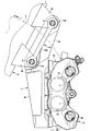
- FIG. 1 is a sectional view taken along line IV-IV of FIG. It is a front view which shows one form example of the caliper body mounting structure of this invention.
- FIG. 1 to 5 are views showing an example of a caliper body mounting structure of the vehicle disc brake of the present invention.
- the arrow A indicates the rotation direction of the disc rotor that rotates integrally with the wheel when the vehicle is moving forward, and the disc feeding side and the disc turning side described below are assumed to be when the vehicle is moving forward.
- a radial mount type caliper body 2 is attached to a pair of caliper mounting portions 3a and 3a provided on the lower end side of a front fork 3 (wheel suspension device) via a caliper bracket 4. Is installed.
- the caliper body 2 has a pair of action portions 2a and 2a supported on the lower end of the front fork 3 and arranged to face each other on both side portions of the disc rotor 5 which rotates integrally with the wheels, and these are straddled over the outer periphery of the disc rotor 5. Cylinder holes 2c and 2c are formed in the working portions 2a and 2a, respectively, which are provided with a bridge portion 2b for connecting and accommodate the pistons 7 and 7 for pressing the friction pad 6 on the disc rotor 5.
- mounting boss portions 2d and 2d are formed in the action portion 2a on the vehicle body mounting side arranged on one side portion of the disc rotor 5, and bolt insertion holes formed in the mounting boss portions 2d and 2d. It is attached to the caliper bracket 4 by using the caliper mounting bolts 8 and 8 that are inserted into the 2e and 2e.
- the mounting boss portions 2d and 2d are the disc shafts connecting the disc rotor 5 rotation center and the caliper body 2 pad pressing center in the direction orthogonal to the disc shaft on the disc insertion side and the disc exit side of the action portion 2a.
- the bolt insertion holes 2e and 2e having a diameter slightly larger than that of the caliper mounting bolts 8 and 8 are formed in the mounting boss portions 2d and 2d by overlaying them in the direction parallel to the virtual line L1 in the orthogonal direction to the disc. It is formed through in a direction parallel to the above-mentioned virtual line L1 orthogonal to the axis.
- the caliper mounting portions 3a and 3a formed on the front fork 3 are projected from the outside of the front fork 3 in the radial direction of the disc and the inside of the radial direction of the disc on the rear side of the vehicle body, and the caliper bracket 4 uses the vehicle body mounting bolt 9. It is attached via a plate-shaped fastening member 10. Bracket mounting holes 3b and 3b having a diameter slightly larger than that of the vehicle body mounting bolts 9 and 9 are formed through the caliper mounting portions 3a and 3a in the disk axial direction.
- the caliper bracket 4 is provided from the vehicle body mounting arm 4a attached to the caliper mounting portions 3a and 3a and the inner end of the vehicle body mounting arm 4a in the radial direction of the disk in a direction substantially orthogonal to the virtual line L1 orthogonal to the disk axis. It is equipped with a caliper body mounting arm 4b that extends.
- the caliper body mounting arm 4b is coaxial with the bolt insertion holes 2e and 2e, and is internally provided with female screw holes 4c and 4c (caliper mounting holes) screwed into the male screw portions 8a and 8a of the caliper mounting bolts 8 and 8. It is provided with boss portions 4d and 4d.
- the vehicle body mounting arm 4a is coaxial with the bracket mounting holes 3b and 3b, and the vehicle body mounting holes 4e and 4e having a diameter slightly larger than that of the vehicle body mounting bolts 9 and 9 are formed through.
- the fastening member 10 is formed in a plate shape in which female threaded portions 10a and 10a arranged at positions corresponding to the bracket mounting holes 3b and 3b and a connecting portion 10b connecting the female threaded portions 10a and 10a are integrally provided.
- the female threaded portions 10a and 10a are formed so as to be screwed into the male threaded portions 9a and 9a of the vehicle body mounting bolts 9 and 9.
- the body mounting arm 4a of the caliper bracket 4 is arranged on the outside of the vehicle body of the caliper mounting portions 3a and 3a of the front fork 3, and the bracket mounting holes on the inside of the vehicle body of the caliper mounting portions 3a and 3a are arranged.
- the female threaded portions 10a and 10a of the fastening member 10 are arranged at positions corresponding to 3b and 3b, and the male threaded portions of the vehicle body mounting bolts 9 and 9 inserted through the vehicle body mounting holes 4e and 4e and the bracket mounting holes 3b and 3b.
- the outer peripheral side surfaces of the discs of the boss portions 4d and 4d of the caliper body mounting arm 4b of the caliper bracket 4 and the inner peripheral side surfaces of the discs of the mounting boss portions 2d and 2d of the caliper body 2 are aligned with each other in the bolt insertion holes 2e and 2e.
- the caliper body 2 is attached to the caliper bracket 4 by inserting the caliper mounting bolts 8 and 8 and fastening the male screw portions 8a and 8a to the female screw holes 4c and 4c.
- the caliper mounting portions 3a and 3a can be made smaller than before while ensuring the mounting rigidity of the radial mount type caliper body 2.
- the radial mount type caliper body 2 can be attached to the caliper mounting portion of the wheel suspension device for attaching the axial mount type caliper body 2, and the radial mount type caliper body can be attached to the axial mount type wheel suspension device. It can be mounted on a wider range of wheel suspension devices, including the caliper mount.
- the shape of the caliper bracket 4 the mounting position of the caliper body 2 can be adjusted according to the size of the outer peripheral diameter of the disc rotor 5 and the dimension of the wheel suspension device, and the layout can be improved. It can be improved.
- the caliper bracket 4 is arranged on the outside of the vehicle body of the caliper mounting portions 3a and 3a, and the fastening member 10 is arranged on the inside of the vehicle body of the caliper mounting portions 3a and 3a.
- the mounting rigidity of the caliper bracket can be increased, even if the caliper body 2 receives a rotational moment generated in the disc rotation direction during braking, the rotational moment can be reliably received by the caliper body and the caliper bracket. It is possible to suppress the behavior of the caliper body 2.
- the fastening member 10 is integrally formed with two female threaded portions 10a and 10a arranged at positions corresponding to the bracket mounting holes 3b and 3b and a connecting portion 10b connecting these female threaded portions 10a and 10a.
- the caliper bracket 4 can be easily assembled, and the caliper bracket 4 can be accurately assembled to the caliper mounting portions 3a and 3a.
- the present invention is not limited to the above-mentioned embodiment, and the number of cylinder holes formed in the caliper body is arbitrary. Further, the shapes of the body mounting arm and the caliper body mounting arm of the caliper bracket may be formed in any shape according to the size and shape of the caliper body. Further, the fastening member may not have the female threaded portion connected by the connecting portion.
Landscapes
- Engineering & Computer Science (AREA)
- General Engineering & Computer Science (AREA)
- Mechanical Engineering (AREA)
- Braking Arrangements (AREA)
Abstract
L'invention concerne une structure de montage de corps d'étrier pour un frein à disque de véhicule, qui peut être montée sur une large gamme de dispositifs de suspension de roue tout en assurant la rigidité de montage d'un corps d'étrier à montage radial. Dans la partie de travail d'un corps d'étrier (2), des trous d'insertion de boulon (2e, 2e) dans une direction orthogonale à un axe de disque sont formés sur les deux côtés dans la direction circonférentielle du disque. Un support d'étrier (4) est formé avec : des trous filetés intérieurement (4c, 4c) (trous de montage d'étrier) dans la direction orthogonale à l'axe de disque, pour monter le corps d'étrier (2) ; et des trous de montage de corps de véhicule (4e, 4e) dans la direction d'axe de disque, pour monter le corps d'étrier (2) sur des parties de montage d'étrier (3a, 3a) qui sont formées sur une fourche avant (3). Le corps d'étrier (2) est monté sur les parties de montage d'étrier (3a, 3a) avec le support d'étrier (4) interposé entre eux.
Priority Applications (1)
| Application Number | Priority Date | Filing Date | Title |
|---|---|---|---|
| JP2022511532A JP7675312B2 (ja) | 2020-03-30 | 2020-12-21 | 車両用ディスクブレーキのキャリパボディ取付け構造 |
Applications Claiming Priority (2)
| Application Number | Priority Date | Filing Date | Title |
|---|---|---|---|
| JP2020059291 | 2020-03-30 | ||
| JP2020-059291 | 2020-03-30 |
Publications (1)
| Publication Number | Publication Date |
|---|---|
| WO2021199530A1 true WO2021199530A1 (fr) | 2021-10-07 |
Family
ID=77927068
Family Applications (1)
| Application Number | Title | Priority Date | Filing Date |
|---|---|---|---|
| PCT/JP2020/047728 Ceased WO2021199530A1 (fr) | 2020-03-30 | 2020-12-21 | Structure de montage de corps d'étrier pour frein à disque de véhicule |
Country Status (3)
| Country | Link |
|---|---|
| JP (1) | JP7675312B2 (fr) |
| TW (1) | TWI879861B (fr) |
| WO (1) | WO2021199530A1 (fr) |
Family Cites Families (4)
| Publication number | Priority date | Publication date | Assignee | Title |
|---|---|---|---|---|
| JP4892571B2 (ja) * | 2009-02-12 | 2012-03-07 | 日信工業株式会社 | 車両用ディスクブレーキのキャリパボディ |
| TWI679356B (zh) * | 2015-06-12 | 2019-12-11 | 日商日信工業股份有限公司 | 車輛用碟式煞車 |
| BR112018070868B1 (pt) * | 2016-05-06 | 2022-07-05 | Hitachi Astemo, Ltd | Freio a disco para veículo. |
| ES2895117T3 (es) * | 2016-06-20 | 2022-02-17 | Hitachi Astemo Ltd | Cuerpo de pinza para freno de disco de vehículo |
-
2020
- 2020-12-21 JP JP2022511532A patent/JP7675312B2/ja active Active
- 2020-12-21 WO PCT/JP2020/047728 patent/WO2021199530A1/fr not_active Ceased
- 2020-12-28 TW TW109146394A patent/TWI879861B/zh active
Non-Patent Citations (4)
| Title |
|---|
| "American Dragers, Maxam Blast Mania radial mount billet chrome caliper set", SET, AMAZON.COM, 5 September 2017 (2017-09-05), Retrieved from the Internet <URL:https://www.amazon.co.jp/%E3%83%96%E3%83%A9%E3%82%B9%E3%83%88%E3%83%9E%E3%83%8B%E3%82%A2-%E3%83%A9%E3%82%B8%E3%82%A2%E3%83%AB%E3%83%9E%E3%82%A6%E3%83%B3%E3%83%88-%E3%82%AF%E3%83%AD%E3%83%BC%E3%83%AO%E3%82%AD%E3%83%A3%E3%83%AA%E3%83%91%E3%83%BC-%E3%80%8CK159-D036G0841/dp/B075CWP3WT> [retrieved on 20210218] * |
| "Caliper support radial mount for upright fork", WEBIKE SHOPPING (ONLINE), 18 January 2008 (2008-01-18), Retrieved from the Internet <URL:https://www.webike.net/sd/1651995> [retrieved on 20210218] * |
| "Ichikoku Cycle Works, 9 1/2 Brake kit (polished rotor)", WEBIKE SHOPPING, 31 August 2011 (2011-08-31), Retrieved from the Internet <URL:https://www.webike.net/sd/20048861> * |
| ANONYMOUS: "9 1/2 (Nine Half) Brake Kit ", ICHIKOKU CYCLE WORKS, 18 February 2021 (2021-02-18), XP055935864, Retrieved from the Internet <URL:http://www.ichikoku.com/harley_davidson/parts/brembo9_5/brembo9_5.html> [retrieved on 20220627] * |
Also Published As
| Publication number | Publication date |
|---|---|
| JP7675312B2 (ja) | 2025-05-14 |
| JPWO2021199530A1 (fr) | 2021-10-07 |
| TW202136660A (zh) | 2021-10-01 |
| TWI879861B (zh) | 2025-04-11 |
Similar Documents
| Publication | Publication Date | Title |
|---|---|---|
| US9291224B2 (en) | Caliper bodies for disc brakes | |
| JP4067689B2 (ja) | 対向ピストン型ディスクブレーキ | |
| JP5267743B1 (ja) | ディスクブレーキ装置及びキャリパ | |
| EP3087291B1 (fr) | Corps d'étrier de frein à disque et étrier de frein à disque | |
| JP2005121174A (ja) | 対向ピストン型ディスクブレーキ | |
| JP2007064296A (ja) | ディスクブレーキ装置及び該ディスクブレーキ装置を備えた自動二輪車 | |
| WO2021199530A1 (fr) | Structure de montage de corps d'étrier pour frein à disque de véhicule | |
| US6305509B1 (en) | Method and apparatus for enhancing vehicle braking efficiency | |
| JP5297341B2 (ja) | 車両用ディスクブレーキのキャリパボディ | |
| US20240280151A1 (en) | Caliper brake | |
| JP4718422B2 (ja) | ディスクブレーキ | |
| JP2009216205A (ja) | ブレーキディスクおよび車両 | |
| US4884663A (en) | Device for supporting and attaching a disk brake caliper | |
| JP2006193148A (ja) | 車両用のコーナ部組立体 | |
| WO2015151210A1 (fr) | Suspension à barres de torsion et parties de plaque utilisées pour cette dernière | |
| JP5357823B2 (ja) | ブレーキ配管構造 | |
| US20230341016A1 (en) | Caliper for opposed piston type disc brake | |
| US20250277513A1 (en) | Axle assembly and off-road vehicle | |
| JP7136027B2 (ja) | ディスクブレーキ | |
| JP2023182435A (ja) | 対向ピストン型ディスクブレーキ用キャリパ | |
| JP4258899B2 (ja) | ディスクブレーキ | |
| US4265339A (en) | Disc brake | |
| KR20060108280A (ko) | 브레이크 디스크 및 그 조립방법 | |
| JP6027834B2 (ja) | ディスクブレーキ | |
| JP2020131821A (ja) | 車輪用ハブ装置 |
Legal Events
| Date | Code | Title | Description |
|---|---|---|---|
| 121 | Ep: the epo has been informed by wipo that ep was designated in this application |
Ref document number: 20928587 Country of ref document: EP Kind code of ref document: A1 |
|
| ENP | Entry into the national phase |
Ref document number: 2022511532 Country of ref document: JP Kind code of ref document: A |
|
| NENP | Non-entry into the national phase |
Ref country code: DE |
|
| 122 | Ep: pct application non-entry in european phase |
Ref document number: 20928587 Country of ref document: EP Kind code of ref document: A1 |