WO2021199746A1 - リードブロックおよび回転コネクタ装置 - Google Patents
リードブロックおよび回転コネクタ装置 Download PDFInfo
- Publication number
- WO2021199746A1 WO2021199746A1 PCT/JP2021/005772 JP2021005772W WO2021199746A1 WO 2021199746 A1 WO2021199746 A1 WO 2021199746A1 JP 2021005772 W JP2021005772 W JP 2021005772W WO 2021199746 A1 WO2021199746 A1 WO 2021199746A1
- Authority
- WO
- WIPO (PCT)
- Prior art keywords
- lead block
- additional
- exposed
- cut surface
- cut
- Prior art date
- Legal status (The legal status is an assumption and is not a legal conclusion. Google has not performed a legal analysis and makes no representation as to the accuracy of the status listed.)
- Ceased
Links
Images









Classifications
-
- H—ELECTRICITY
- H01—ELECTRIC ELEMENTS
- H01R—ELECTRICALLY-CONDUCTIVE CONNECTIONS; STRUCTURAL ASSOCIATIONS OF A PLURALITY OF MUTUALLY-INSULATED ELECTRICAL CONNECTING ELEMENTS; COUPLING DEVICES; CURRENT COLLECTORS
- H01R35/00—Flexible or turnable line connectors, i.e. the rotation angle being limited
- H01R35/04—Turnable line connectors with limited rotation angle with frictional contact members
-
- H—ELECTRICITY
- H01—ELECTRIC ELEMENTS
- H01R—ELECTRICALLY-CONDUCTIVE CONNECTIONS; STRUCTURAL ASSOCIATIONS OF A PLURALITY OF MUTUALLY-INSULATED ELECTRICAL CONNECTING ELEMENTS; COUPLING DEVICES; CURRENT COLLECTORS
- H01R35/00—Flexible or turnable line connectors, i.e. the rotation angle being limited
- H01R35/02—Flexible line connectors without frictional contact members
- H01R35/025—Flexible line connectors without frictional contact members having a flexible conductor wound around a rotation axis
-
- B—PERFORMING OPERATIONS; TRANSPORTING
- B29—WORKING OF PLASTICS; WORKING OF SUBSTANCES IN A PLASTIC STATE IN GENERAL
- B29C—SHAPING OR JOINING OF PLASTICS; SHAPING OF MATERIAL IN A PLASTIC STATE, NOT OTHERWISE PROVIDED FOR; AFTER-TREATMENT OF THE SHAPED PRODUCTS, e.g. REPAIRING
- B29C45/00—Injection moulding, i.e. forcing the required volume of moulding material through a nozzle into a closed mould; Apparatus therefor
- B29C45/14—Injection moulding, i.e. forcing the required volume of moulding material through a nozzle into a closed mould; Apparatus therefor incorporating preformed parts or layers, e.g. injection moulding around inserts or for coating articles
- B29C45/14639—Injection moulding, i.e. forcing the required volume of moulding material through a nozzle into a closed mould; Apparatus therefor incorporating preformed parts or layers, e.g. injection moulding around inserts or for coating articles for obtaining an insulating effect, e.g. for electrical components
-
- B—PERFORMING OPERATIONS; TRANSPORTING
- B60—VEHICLES IN GENERAL
- B60R—VEHICLES, VEHICLE FITTINGS, OR VEHICLE PARTS, NOT OTHERWISE PROVIDED FOR
- B60R16/00—Electric or fluid circuits specially adapted for vehicles and not otherwise provided for; Arrangement of elements of electric or fluid circuits specially adapted for vehicles and not otherwise provided for
- B60R16/02—Electric or fluid circuits specially adapted for vehicles and not otherwise provided for; Arrangement of elements of electric or fluid circuits specially adapted for vehicles and not otherwise provided for electric constitutive elements
- B60R16/023—Electric or fluid circuits specially adapted for vehicles and not otherwise provided for; Arrangement of elements of electric or fluid circuits specially adapted for vehicles and not otherwise provided for electric constitutive elements for transmission of signals between vehicle parts or subsystems
- B60R16/027—Electric or fluid circuits specially adapted for vehicles and not otherwise provided for; Arrangement of elements of electric or fluid circuits specially adapted for vehicles and not otherwise provided for electric constitutive elements for transmission of signals between vehicle parts or subsystems between relatively movable parts of the vehicle, e.g. between steering wheel and column
-
- H—ELECTRICITY
- H01—ELECTRIC ELEMENTS
- H01R—ELECTRICALLY-CONDUCTIVE CONNECTIONS; STRUCTURAL ASSOCIATIONS OF A PLURALITY OF MUTUALLY-INSULATED ELECTRICAL CONNECTING ELEMENTS; COUPLING DEVICES; CURRENT COLLECTORS
- H01R13/00—Details of coupling devices of the kinds covered by groups H01R12/70 or H01R24/00 - H01R33/00
- H01R13/40—Securing contact members in or to a base or case; Insulating of contact members
- H01R13/405—Securing in non-demountable manner, e.g. moulding, riveting
-
- H—ELECTRICITY
- H01—ELECTRIC ELEMENTS
- H01R—ELECTRICALLY-CONDUCTIVE CONNECTIONS; STRUCTURAL ASSOCIATIONS OF A PLURALITY OF MUTUALLY-INSULATED ELECTRICAL CONNECTING ELEMENTS; COUPLING DEVICES; CURRENT COLLECTORS
- H01R43/00—Apparatus or processes specially adapted for manufacturing, assembling, maintaining, or repairing of line connectors or current collectors or for joining electric conductors
-
- H—ELECTRICITY
- H01—ELECTRIC ELEMENTS
- H01R—ELECTRICALLY-CONDUCTIVE CONNECTIONS; STRUCTURAL ASSOCIATIONS OF A PLURALITY OF MUTUALLY-INSULATED ELECTRICAL CONNECTING ELEMENTS; COUPLING DEVICES; CURRENT COLLECTORS
- H01R43/00—Apparatus or processes specially adapted for manufacturing, assembling, maintaining, or repairing of line connectors or current collectors or for joining electric conductors
- H01R43/20—Apparatus or processes specially adapted for manufacturing, assembling, maintaining, or repairing of line connectors or current collectors or for joining electric conductors for assembling or disassembling contact members with insulating base, case or sleeve
- H01R43/24—Assembling by moulding on contact members
-
- H—ELECTRICITY
- H01—ELECTRIC ELEMENTS
- H01R—ELECTRICALLY-CONDUCTIVE CONNECTIONS; STRUCTURAL ASSOCIATIONS OF A PLURALITY OF MUTUALLY-INSULATED ELECTRICAL CONNECTING ELEMENTS; COUPLING DEVICES; CURRENT COLLECTORS
- H01R9/00—Structural associations of a plurality of mutually-insulated electrical connecting elements, e.g. terminal strips or terminal blocks; Terminals or binding posts mounted upon a base or in a case; Bases therefor
- H01R9/22—Bases, e.g. strip, block, panel
- H01R9/24—Terminal blocks
Definitions
- the technology disclosed in the present application relates to a lead block and a rotary connector device.
- Patent Documents 1 to 4 describe a rotary connector device having a lead block.
- the technical issue disclosed in the present application is to reduce the manufacturing cost of the lead block.
- the lead block according to the first feature includes a lead block main body including an electrically insulating material, and a plurality of bus bars partially embedded in the lead block main body and containing a conductive material.
- the plurality of bus bars include a plurality of exposed portions exposed from the lead block main body and corresponding to the plurality of bus bars.
- the plurality of exposed portions extend in the longitudinal direction and are arranged at intervals in the arrangement direction orthogonal to the longitudinal direction.
- the plurality of exposed parts includes at least one first exposed part.
- At least one first exposed portion includes a first surface and a first additional surface arranged behind the first surface in the arrangement direction.
- the first surface includes a first cut surface having an area smaller than the area of the first surface.
- the first additional surface includes a first additional cut surface having an area smaller than the area of the first additional surface.
- the first cut surface having an area smaller than the area of the first surface is arranged on the first surface, and the first additional cut surface has an area smaller than the area of the first additional surface. Is arranged on the first additional surface, so that the amount of material cut from the plurality of bus bars and discarded during manufacturing can be reduced. As a result, the manufacturing cost of the lead block can be reduced.
- the first surface includes the first adjacent surface adjacent to the first cut surface.
- the first additional plane includes a first additional adjacent plane adjacent to the first additional cut plane.
- the appearance of the first cut surface is different from the appearance of the first adjacent surface.
- the appearance of the first additional cut surface is different from the appearance of the first additional adjacent surface.
- the surface finishing steps of the first cut surface and the first additional cut surface can be omitted.
- the manufacturing cost of the lead block can be further reduced as compared with the case where the surface finish of the first cut surface and the first additional cut surface is performed.
- the first cut surface is deviated from the first adjacent surface in the arrangement direction.
- the first additional cut surface is deviated from the first additional adjacent surface in the arrangement direction.
- the first additional cut surface is arranged behind the first cut surface in the arrangement direction. ..
- the lead block according to the fifth feature for example, when a connecting bar connecting a plurality of exposed parts is cut from the plurality of exposed parts at the time of manufacturing, deformation of the plurality of exposed parts can be suppressed.
- the length of the first cut surface in the arrangement direction is the length of the first surface in the arrangement direction. Shorter than that. The length of the first additional cut surface in the arrangement direction is shorter than the length of the first additional cut surface in the arrangement direction.
- the length of the first cut surface is equal to the length of the first surface and / or the length of the first additional cut surface is equal to the length of the first additional surface.
- Less material can be cut and discarded from multiple busbars. As a result, the manufacturing cost of the lead block can be further reduced.
- the plurality of exposed parts include the second exposed part.
- the second exposed portion includes a second surface facing at least one first exposed portion in the arrangement direction and a second additional surface arranged behind the second surface in the arrangement direction.
- the second surface includes a second cut surface having an area smaller than the area of the second surface.
- the material is cut from a plurality of bus bars and discarded at the time of manufacturing. Can be reduced. As a result, the manufacturing cost of the lead block can be further reduced.
- one of the plurality of bus bars has a first protruding portion protruding from the second additional surface of the second exposed portion in the arrangement direction. include.
- the first protrusion is at least partially embedded in the lead block body.
- the connection strength between the second exposed portion and the lead block main body can be improved while reducing the manufacturing cost of the lead block. Can be enhanced.
- the connecting bar that connects a plurality of exposed portions includes the first protruding portion at the time of manufacturing, a part of the connecting bar can be used to improve the connecting strength, and the connecting strength between the second exposed portion and the lead block main body can be increased. Effective utilization of lead block material can be promoted while increasing.
- the plurality of exposed portions include the third exposed portion.
- the third exposed portion includes a third surface facing at least one first exposed portion in the arrangement direction and a third additional surface arranged behind the third surface in the arrangement direction.
- the third surface includes a third cut surface having an area smaller than the area of the third surface.
- the material is cut from a plurality of bus bars and discarded at the time of manufacturing. Can be reduced. As a result, the manufacturing cost of the lead block can be further reduced.
- one of the plurality of bus bars has a second protruding portion protruding from the third additional surface of the third exposed portion in the arrangement direction. include.
- the second protrusion is at least partially embedded in the lead block body.
- the connection strength between the third exposed portion and the lead block main body can be improved while reducing the manufacturing cost of the lead block. Can be enhanced.
- the connecting bar that connects a plurality of exposed portions includes the second protruding portion at the time of manufacturing, a part of the connecting bar can be used to improve the connecting strength, and the connecting strength between the third exposed portion and the lead block main body can be increased. Effective utilization of lead block material can be promoted while increasing.
- the plurality of bus bars are at least one first bus bar including at least one first exposed portion.
- At least one first bus bar includes a first end and a first additional end.
- the first cut plane and the first additional cut plane are arranged between the first end and the first additional end.
- a plurality of bus bars can be manufactured with less material. Is easy to hold integrally.
- the first end portion is exposed from the lead block main body.
- the first additional end is arranged inside the contour of the lead block body when viewed from the orthogonal direction orthogonal to the longitudinal direction and the arrangement direction.
- the first additional end is a cable or the like, as compared with the case where the first additional end is arranged on the contour of the lead block body or outside the contour of the lead block body. It is possible to suppress contact with the member of.
- the first additional end portion is at least partially embedded in the lead block main body.
- the lead block according to the thirteenth feature it is possible to reliably prevent the first additional end from coming into contact with another member such as a cable.
- the lead block main body includes an opening.
- the first cut surface and the first additional cut surface are arranged in the opening.
- the connecting bar connecting the plurality of exposed portions can be cut from the plurality of connecting portions through the openings at the time of manufacturing.
- the rotary connector device includes a stator, a rotating body rotatably provided about the stator about the rotation axis, and a lead block according to any one of the first to fourteenth features. Be prepared.
- the manufacturing cost of the lead block can be reduced, so that the manufacturing cost of the rotary connector device can be reduced.
- the method for manufacturing a lead block according to the sixteenth feature is such that a plurality of exposed portions expose a bus bar plate including a plurality of bus bars and a connecting bar for connecting the plurality of exposed portions of the plurality of bus bars to each other from the lead block main body.
- a molding step of embedding in the lead block main body by insert molding and a cutting step of cutting the connecting bar from a plurality of exposed portions are provided.
- the lead block manufacturing method according to the sixteenth feature it is possible to reduce the amount of material that is cut and discarded from a plurality of bus bars. As a result, the manufacturing cost of the lead block can be reduced.
- the method for manufacturing the lead block according to the seventeenth feature is the method for manufacturing the lead block according to the sixteenth feature. Includes a step of embedding the busbar plate in the lead block body by insert molding so that it is arranged.
- the peripheral portions of a plurality of exposed portions can be held by the lead block main body.
- the cutting step cuts the connecting bar from the plurality of exposed portions through the openings of the lead block main body. Including the process.
- the connecting bar can be cut from the plurality of exposed portions while the peripheral portions of the plurality of exposed portions are held by the lead block main body. This stabilizes the cutting work.
- a part of the connecting bar is inside the lead block main body. Including the step of embedding the bus bar plate in the lead block body by insert molding so as to be embedded in the lead block.
- connection strength between the plurality of exposed portions and the lead block main body can be increased.
- the method for manufacturing the lead block according to any one of the sixteenth to nineteenth features is a press working step of forming a bus bar plate from a plate containing a conductive material by press working. Further prepare.
- the remaining portion separated from the bus bar plate by press working can be reduced.
- the manufacturing cost of the lead block can be reduced.
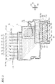
- FIG. 1 is a plan view of the rotary connector device according to the present embodiment.
- FIG. 2 is a cross-sectional view of the rotary connector device shown in FIG.
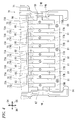
- FIG. 3 is a side view of the lead block of the rotary connector device shown in FIG.
- FIG. 4 is a partial side view of the lead block shown in FIG.
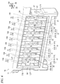
- FIG. 5 is a partial perspective view of the lead block shown in FIG.
- FIG. 6 is a partial perspective view of the lead block shown in FIG.
- FIG. 7 is a cross-sectional view of the lead block in lines VII-VII of FIG.
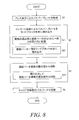
- FIG. 8 is a flowchart showing a method of manufacturing the lead block shown in FIG.
- FIG. 9 is a plan view showing a press working process of the lead block shown in FIG. FIG.
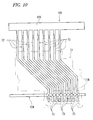
- FIG. 10 is a plan view showing a molding process of the lead block shown in FIG.
- FIG. 11 is a plan view showing a lead block cutting step and a carrier cutting step shown in FIG.
- FIG. 12 is a diagram showing the surface state of the first surface of the lead block shown in FIG.
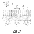
- FIG. 13 is a diagram showing the surface state of the first additional surface of the lead block shown in FIG.
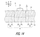
- FIG. 14 is a diagram showing the surface state of the second surface of the lead block shown in FIG.
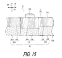
- FIG. 15 is a diagram showing the surface state of the third surface of the lead block shown in FIG.
- FIG. 16 is a diagram showing the surface state of the first surface of the lead block according to the modified example.
- FIG. 17 is a diagram showing the surface state of the first surface of the lead block according to the modified example.
- FIG. 18 shows the positional relationship between the first cut surface and the first adjacent surface of the lead block and the positional relationship between the first additional cut surface and the first additional adjacent surface according to the modified example.
- FIG. 19 shows the positional relationship between the first cut surface and the first adjacent surface of the lead block and the positional relationship between the first additional cut surface and the first additional adjacent surface according to the modified example.
- the rotary connector device 1 includes a stator 10 and a rotating body 20.
- the stator 10 is configured to be attached to the vehicle body.
- the rotating body 20 is rotatably provided around the rotation axis A1 with respect to the stator 10.
- the rotating body 20 is configured to be fixed to the steering wheel.
- the rotary connector device 1 includes a first connector 30 and a second connector 40.
- the first connector 30 is provided on the stator 10.
- the second connector 40 is provided on the rotating body 20.
- the first connector 30 is configured so that the vehicle body side connector is detachably attached.
- the first connector 30 includes a first connector accommodating portion 31 into which a vehicle body side connector is inserted.
- the vehicle body side connector is electrically connected to an electric circuit such as a control device.
- the second connector 40 is configured so that the steering side connector is detachably mounted.
- the second connector 40 includes a second connector accommodating portion 41 into which the steering side connector is inserted.
- the steering side connector is electrically connected to electric circuits such as steering wheel switches and airbag devices.
- the stator 10 and the rotating body 20 define a cable accommodating space 50 provided so as to surround the rotating axis A1 between the stator 10 and the rotating body 20.
- the cable accommodating space 50 has an annular shape and extends in the circumferential direction D2 with respect to the rotation axis A1.
- the rotary connector device 1 includes an electric cable 60.
- the electric cable 60 electrically connects the first connector 30 to the second connector 40.
- the electric cable 60 is arranged in the cable accommodating space 50.
- the electric cable 60 is flexible and has a flat shape.
- the electric cable 60 may also be referred to as a flexible flat cable.
- the rotary connector device 1 includes a lead block 70.
- the rotary connector device 1 includes a plurality of lead blocks 70.
- the lead blocks 70A and 70B of the plurality of lead blocks 70 are attached to the stator 10.
- the lead blocks 70A and 70B are arranged in the first connector accommodating portion 31.
- the lead blocks 70C and 70D of the plurality of lead blocks 70 are attached to the rotating body 20.
- the lead blocks 70C and 70D are arranged in the second connector accommodating portion 41.
- the first connector 30 includes lead blocks 70A and 70B.
- the second connector 40 includes lead blocks 70C and 70D.
- the total number of lead blocks 70 is not limited to this embodiment.
- the lead block 70 includes a lead block main body 71 and a plurality of bus bars 72.
- the lead block body 71 contains an electrically insulating material.
- the plurality of bus bars 72 are partially embedded in the lead block body 71 and include a conductive material.
- the electrically insulating material includes, for example, a resin material.
- the conductive material includes a metallic material such as copper.
- the plurality of bus bars 72 are electrically insulated from each other by the lead block main body 71.
- the plurality of bus bars 72 are electrically connected to each of the plurality of wires included in the electric cable 60 (see FIG. 2).
- the plurality of bus bars 72 include a plurality of exposed portions 73 exposed from the lead block main body 71 and corresponding to the plurality of bus bars 72, respectively.
- the bus bar 72 includes an exposed portion 73.
- the plurality of exposed portions 73 extend in the longitudinal direction D4 and are arranged at intervals in the arrangement direction D5 orthogonal to the longitudinal direction D4.
- the plurality of exposed portions 73 include at least one first exposed portion 74.
- the plurality of exposed portions 73 include a plurality of first exposed portions 74.
- the total number of the first exposed portions 74 is not limited to this embodiment.
- the plurality of exposed portions 73 include the second exposed portion 75.
- the plurality of exposed portions 73 include a third exposed portion 76.
- At least one first exposed portion 74 is arranged between the second exposed portion 75 and the third exposed portion 76 in the arrangement direction D5.
- the plurality of first exposed portions 74 are arranged between the second exposed portion 75 and the third exposed portion 76 in the arrangement direction D5.
- the plurality of first exposed portions 74, the second exposed portion 75, and the third exposed portion 76 are arranged at intervals in the arrangement direction D5.
- the plurality of bus bars 72 includes at least one first bus bar 77 including at least one first exposed portion 74. At least one first bus bar 77 includes a first end 77A and a first additional end 77B. In this embodiment, the plurality of bus bars 72 includes a plurality of first bus bars 77 including a plurality of first exposed portions 74. The plurality of bus bars 72 include a first end portion 77A and a first additional end portion 77B. However, the total number of the first bus bars 77 is not limited to this embodiment.
- the plurality of bus bars 72 include a second bus bar 78 including a second exposed portion 75.
- the plurality of bus bars 72 include a third bus bar 79 including a third exposed portion 76.
- the second bus bar 78 includes a second end 78A and a second additional end 78B.
- the third bus bar 79 includes a third end 79A and a third additional end 79B. At least one of the second bus bar 78 and the third bus bar 79 may be omitted from the plurality of bus bars 72.
- the first end 77A is exposed from the lead block main body 71.
- the first bus bar 77 includes a first pin terminal 77C exposed from the lead block main body 71.
- the first pin terminal 77C projects from the lead block main body 71 in the longitudinal direction D4.
- the first pin terminal 77C includes a first end portion 77A. When viewed from the orthogonal direction D6 orthogonal to the longitudinal direction D4 and the arrangement direction D5, the first end portion 77A is arranged outside the contour 71A of the lead block main body 71.
- the first additional end portion 77B is arranged inside the contour of the lead block main body 71.
- the first additional end 77B is at least partially embedded in the lead block body 71.
- the first additional end portion 77B is partially embedded in the lead block main body 71, but a part of the surface of the first additional end portion 77B is exposed from the lead block main body 71.
- the entire first additional end portion 77B may be embedded in the lead block main body 71.
- At least one first exposed portion 74 includes a first surface 80 and a first additional surface 81.
- the first additional surface 81 is arranged on the back side of the first surface 80 in the arrangement direction D5.
- Each of the plurality of first exposed portions 74 includes a first surface 80 and a first additional surface 81.
- the second exposed portion 75 includes a second surface 83 and a second additional surface 84.
- the second surface 83 faces at least one first exposed portion 74 in the arrangement direction D5.
- the second additional surface 84 is arranged on the back side of the second surface 83 in the arrangement direction D5.
- the third exposed portion 76 includes the third surface 85 and the third additional surface 86.
- the third surface 85 faces at least one first exposed portion 74 in the arrangement direction D5.
- the third additional surface 86 is arranged on the back side of the third surface 85 in the arrangement direction D5.
- One of the plurality of bus bars 72 includes a first protruding portion 87 projecting from the second additional surface 84 of the second exposed portion 75 in the arrangement direction D5.
- the second bus bar 78 includes the first protrusion 87.
- the first protrusion 87 is at least partially embedded in the lead block body 71.
- the first protruding portion 87 is partially embedded in the lead block main body 71.
- the entire first protruding portion 87 may be embedded in the lead block main body 71.
- the first protruding portion 87 may be omitted from the plurality of bus bars 72.
- One of the plurality of bus bars 72 includes a second protruding portion 88 projecting from the third additional surface 86 of the third exposed portion 76 in the arrangement direction D5.
- the third bus bar 79 includes a second protrusion 88.
- the second protrusion 88 is at least partially embedded in the lead block body 71.
- the second protruding portion 88 is partially embedded in the lead block main body 71.
- the entire second protrusion 88 may be embedded in the lead block main body 71.
- the second protruding portion 88 may be omitted from the plurality of bus bars 72.
- the lead block main body 71 includes an opening 71B.
- the plurality of exposed portions 73 are arranged at least partially in the opening 71B when viewed from the orthogonal direction D6.
- the plurality of first exposed portions 74, the second exposed portion 75, and the third exposed portion 76 are arranged at least partially in the opening 71B when viewed from the orthogonal direction D6.
- the first surface 80 includes a first cut surface 90 having an area smaller than the area of the first surface 80.
- the first cut surface 90 is arranged in the opening 71B.
- the length L11 of the first cut surface 90 in the longitudinal direction D4 is shorter than the length L12 of the first surface 80 in the longitudinal direction D4.
- the first surface 80 includes a first adjacent surface 80A adjacent to the first cut surface 90.
- the first surface 80 includes a first adjacent surface 80B adjacent to the first cut surface 90.
- the appearance of the first cut surface 90 is different from the appearance of the first adjacent surface 80A.
- the appearance of the first cut surface 90 is different from the appearance of the first adjacent surface 80B.
- the appearance of the first adjacent surface 80A is the same as the appearance of the first adjacent surface 80B.
- the first cut surface 90 is a surface formed when the connecting bar 104 (see FIGS. 9 to 11) is cut from the plurality of first exposed portions 74 at the time of manufacturing the lead block 70.
- the first adjacent surfaces 80A and 80B are surfaces formed by, for example, pressing (for example, shearing), whereas the first cut surface 90 is first after the first adjacent surfaces 80A and 80B. It is a surface formed by a process different from that of the adjacent surfaces 80A and 80B.
- the first cut surface 90 is, for example, a surface formed by press working (for example, shearing) in the same manner as the first adjacent surfaces 80A and 80B.
- the first adjacent surface 80A includes a shear section 80C and a fracture surface 80D.
- the fracture surface 80D is adjacent to the shear surface 80C in the orthogonal direction D6.
- the shear plane 80C is a surface formed by shearing a material by a punch and a die during shearing, and includes a plurality of streaks extending in one direction (for example, orthogonal direction D6).
- the fracture surface 80D is a surface formed by breaking after a part of the material is sheared by a punch and a die during shearing, and includes fine irregularities. Therefore, the appearance of the shear section 80C is different from the appearance of the fracture surface 80D.
- the first adjacent surface 80B includes a shear section 80E and a fracture surface 80F.
- the fracture surface 80F is adjacent to the shear surface 80E in the orthogonal direction D6.
- the shear plane 80E is a surface formed by shearing a material by a punch and a die during shearing, and includes a plurality of streaks extending in one direction (for example, orthogonal direction D6).
- the fracture surface 80F is a surface formed by breaking after a part of the material is sheared by a punch and a die during shearing, and includes fine irregularities. Therefore, the appearance of the shear section 80E is different from the appearance of the fracture surface 80F.
- the first cut surface 90 includes a first shear section 90A and a first fracture surface 90B.
- the first fracture surface 90B is adjacent to the first shear section 90A in the orthogonal direction D6.
- the first shear section 90A is a surface formed by shearing a material by a punch and a die during shearing, and includes a plurality of streaks extending in one direction (for example, orthogonal direction D6).
- the first fracture surface 90B is a surface formed by breaking after a part of the material is sheared by a punch and a die during shearing, and includes fine irregularities. Therefore, the appearance of the first shear section 90A is different from the appearance of the first fracture surface 90B.
- the length of the first shear section 90A in the orthogonal direction D6 is different from the length of the shear sections 80C and 80E in the orthogonal direction D6.
- the length of the first fracture surface 90B in the orthogonal direction D6 is different from the length of the fracture surfaces 80D and 80F in the orthogonal direction D6. Therefore, the appearance of the first cut surface 90 is different from the appearance of the first adjacent surfaces 80A and 80B.
- the first cut surface 90 may be a surface that has been surface-finished after the connecting bar 104 has been cut from the plurality of first exposed portions 74.
- the first adjacent surfaces 80A and 80B may be surface-finished surfaces.
- the first shear section 90A and the first fracture surface 90B are at least partially replaced by the finished surface.
- the shear section 80C and fracture surface 80D are at least partially replaced by the finished surface.
- the shear section 80E and fracture surface 80F are at least partially replaced by the finished surface. Therefore, the appearance of the first cut surface 90 may be the same as the appearance of the first adjacent surfaces 80A and 80B.
- the first additional surface 81 includes a first additional cut surface 91 having an area smaller than the area of the first additional surface 81.
- the first additional cut surface 91 is arranged in the opening 71B.
- the length L13 of the first additional cut surface 91 in the longitudinal direction D4 is shorter than the length L14 of the first additional surface 81 in the longitudinal direction D4.
- the first additional surface 81 includes a first additional adjacent surface 81A adjacent to the first additional cut surface 91.
- the first additional surface 81 includes a first additional adjacent surface 81B adjacent to the first additional cut surface 91.
- the appearance of the first additional cut surface 91 is different from the appearance of the first additional adjacent surface 81A.
- the appearance of the first additional cut surface 91 is different from the appearance of the first additional adjacent surface 81B.
- the appearance of the first additional adjacent surface 81A is the same as the appearance of the first additional adjacent surface 81B.
- the first additional cut surface 91 is arranged on the back side of the first cut surface 90 (see FIG. 5) in the arrangement direction D5.
- the first additional cut surface 91 is arranged at the same position as the first cut surface 90 (see FIG. 5) in the longitudinal direction D4.
- the first additional cut surface 91 may not be arranged on the back side of the first cut surface 90 (see FIG. 5) in the arrangement direction D5.
- the first additional cut surface 91 may deviate from the first cut surface 90 (see FIG. 5) in the longitudinal direction D4.
- the first additional cut surface 91 is a surface formed when the connecting bar 104 (see FIGS. 9 to 11) is cut from the plurality of first exposed portions 74 at the time of manufacturing the lead block 70.
- the first additional adjacent surfaces 81A and 81B are surfaces formed by, for example, pressing (for example, shearing), whereas the first additional cut surface 91 is more than the first additional adjacent surfaces 81A and 81B. It is a surface formed later in a process different from that of the first additional adjacent surfaces 81A and 81B.
- the first additional cut surface 91 is, for example, a surface formed by press working (for example, shearing) in the same manner as the first additional adjacent surfaces 81A and 81B.
- the first additional adjacent surface 81A includes an additional shear section 81C and an additional fracture surface 81D.
- the additional fracture surface 81D is adjacent to the additional shear section 81C in the orthogonal direction D6.
- the additional shear section 81C is a surface formed by shearing the material by a punch and a die during shearing, and includes a plurality of streaks extending in one direction (eg, orthogonal direction D6).
- the additional fracture surface 81D is a surface formed by breaking after a part of the material is sheared by a punch and a die during shearing, and includes fine irregularities. Therefore, the appearance of the additional shear section 81C is different from the appearance of the additional fracture surface 81D.
- the first additional adjacent surface 81B includes an additional shear section 81E and an additional fracture surface 81F.
- the additional fracture surface 81F is adjacent to the additional shear section 81E in the orthogonal direction D6.
- the additional shear section 81E is a surface formed by shearing the material by a punch and a die during shearing, and includes a plurality of streaks extending in one direction (eg, orthogonal direction D6).
- the additional fracture surface 81F is a surface formed by breaking after a part of the material is sheared by a punch and a die during shearing, and includes fine irregularities. Therefore, the appearance of the additional shear section 81E is different from the appearance of the additional fracture surface 81F.
- the first additional cut surface 91 includes a first additional shear section 91A and a first additional fracture surface 91B.
- the first additional fracture surface 91B is adjacent to the first additional shear section 91A in the orthogonal direction D6.
- the first additional shear section 91A is a surface formed by shearing a material by a punch and a die during shearing, and includes a plurality of streaks extending in one direction (for example, orthogonal direction D6).
- the first additional fracture surface 91B is a surface formed by breaking after a part of the material is sheared by a punch and a die during shearing, and includes fine irregularities. Therefore, the appearance of the first additional shear section 91A is different from the appearance of the first additional shear section 91B.
- the length of the first additional shear section 91A in the orthogonal direction D6 is different from the length of the additional shear sections 81C and 81E in the orthogonal direction D6.
- the length of the first additional fracture surface 91B in the orthogonal direction D6 is different from the length of the additional fracture surfaces 81D and 81F in the orthogonal direction D6. Therefore, the appearance of the first additional cut surface 91 is different from the appearance of the first additional adjacent surfaces 81A and 81B.
- the first additional cut surface 91 may be a surface that has been surface-finished after the connecting bar 104 has been cut from the plurality of first exposed portions 74.
- the first additional adjacent surfaces 81A and 81B may be surface-finished surfaces.
- the appearance of the first additional cut surface 91 may be the same as the appearance of the first additional adjacent surfaces 81A and 81B.
- the second surface 83 includes a second cut surface 93 having an area smaller than the area of the second surface 83.
- the second cut surface 93 is arranged in the opening 71B.
- the length L21 of the second cut surface 93 in the longitudinal direction D4 is shorter than the length L22 of the second surface 83 in the longitudinal direction D4.
- the second surface 83 includes second adjacent surfaces 83A and 83B adjacent to the second cut surface 93.
- the appearance of the second cut surface 93 is different from the appearance of each of the second adjacent surfaces 83A and 83B.
- the appearance of the second adjacent surface 83A is the same as the appearance of the second adjacent surface 83B.
- the second cut surface 93 is a surface formed when the connecting bar 104 (see FIGS. 9 to 11) is cut from the plurality of first exposed portions 74 at the time of manufacturing the lead block 70.
- the second adjacent surfaces 83A and 83B are surfaces formed by, for example, pressing (for example, shearing), whereas the second cut surface 93 is a second surface after the second adjacent surfaces 83A and 83B. It is a surface formed by a process different from that of the adjacent surfaces 83A and 83B.
- the second cut surface 93 is, for example, a surface formed by press working (for example, shearing) in the same manner as the second adjacent surfaces 83A and 83B.
- the second adjacent surface 83A includes a shear section 83C and a fracture surface 83D.
- the fracture surface 83D is adjacent to the shear surface 83C in the orthogonal direction D6.
- the shear plane 83C is a surface formed by shearing a material by a punch and a die during shearing, and includes a plurality of streaks extending in one direction (for example, orthogonal direction D6).
- the fracture surface 83D is a surface formed by breaking after a part of the material is sheared by a punch and a die during shearing, and includes fine irregularities. Therefore, the appearance of the shear section 83C is different from the appearance of the fracture surface 83D.
- the second adjacent surface 83B includes a shear section 83E and a fracture surface 83F.
- the fracture surface 83F is adjacent to the shear surface 83E in the orthogonal direction D6.
- the shear plane 83E is a surface formed by shearing a material by a punch and a die during shearing, and includes a plurality of streaks extending in one direction (for example, orthogonal direction D6).
- the fracture surface 83F is a surface formed by breaking after a part of the material is sheared by a punch and a die during shearing, and includes fine irregularities. Therefore, the appearance of the shear section 83E is different from the appearance of the fracture surface 83F.
- the second cut surface 93 includes a second shear section 93A and a second fracture surface 93B.
- the second fracture surface 93B is adjacent to the second shear section 93A in the orthogonal direction D6.
- the second shear section 93A is a surface formed by shearing the material by a punch and a die during shearing, and includes a plurality of streaks extending in one direction (for example, the orthogonal direction D6).
- the second fracture surface 93B is a surface formed by breaking after a part of the material is sheared by a punch and a die during shearing, and includes fine irregularities. Therefore, the appearance of the second shear section 93A is different from the appearance of the second fracture surface 93B.
- the length of the second shear section 93A in the orthogonal direction D6 is different from the length of the shear sections 83C and 83E in the orthogonal direction D6.
- the length of the second fracture surface 93B in the orthogonal direction D6 is different from the length of the fracture surfaces 83D and 83F in the orthogonal direction D6. Therefore, the appearance of the second cut surface 93 is different from the appearance of the second adjacent surfaces 83A and 83B.
- the second cut surface 93 may be a surface that has been surface-finished after the connecting bar 104 has been cut from the plurality of first exposed portions 74.
- the second adjacent surfaces 83A and 80B may be surface-finished surfaces.
- the second shear section 93A and the second fracture surface 93B are at least partially replaced by the finished surface.
- the shear section 83C and fracture surface 83D are at least partially replaced by the finished surface.
- the shear section 83E and the fracture surface 83F are at least partially replaced by the finished surface. Therefore, the appearance of the second cut surface 93 may be the same as the appearance of the second adjacent surfaces 83A and 83B.
- the third surface 85 includes a third cut surface 95 having an area smaller than the area of the third surface 85.
- the third cut surface 95 is arranged in the opening 71B.
- the length L31 of the third cut surface 95 in the longitudinal direction D4 is shorter than the length L32 of the third surface 85 in the longitudinal direction D4.
- the third surface 85 includes third adjacent surfaces 85A and 85B adjacent to the third cut surface 95.
- the appearance of the third cut surface 95 is different from the appearance of each of the third adjacent surfaces 85A and 85B.
- the appearance of the third adjacent surface 85A is the same as the appearance of the third adjacent surface 85B.
- the third cut surface 95 is a surface formed when the connecting bar 104 (see FIGS. 9 to 11) is cut from the plurality of first exposed portions 74 at the time of manufacturing the lead block 70.
- the third adjacent surfaces 85A and 85B are surfaces formed by, for example, pressing (for example, shearing), whereas the third cut surface 95 is a third after the third adjacent surfaces 85A and 85B. It is a surface formed by a process different from that of the adjacent surfaces 85A and 85B.
- the third cut surface 95 is, for example, a surface formed by press working (for example, shearing) in the same manner as the third adjacent surfaces 85A and 85B.
- the third adjacent surface 85A includes a shear section 85C and a fracture surface 85D.
- the fracture surface 85D is adjacent to the shear surface 85C in the orthogonal direction D6.
- the shear plane 85C is a surface formed by shearing the material by a punch and a die during shearing, and includes a plurality of streaks extending in one direction (for example, orthogonal direction D6).
- the fracture surface 85D is a surface formed by breaking after a part of the material is sheared by a punch and a die during shearing, and includes fine irregularities. Therefore, the appearance of the shear section 85C is different from the appearance of the fracture surface 85D.
- the third adjacent surface 85B includes a shear section 85E and a fracture surface 85F.
- the fracture surface 85F is adjacent to the shear surface 85E in the orthogonal direction D6.
- the shear section 85E is a surface formed by shearing the material by a punch and a die during shearing, and includes a plurality of streaks extending in one direction (for example, orthogonal direction D6).
- the fracture surface 85F is a surface formed by breaking after a part of the material is sheared by a punch and a die during shearing, and includes fine irregularities. Therefore, the appearance of the shear section 85E is different from the appearance of the fracture surface 85F.
- the third cut surface 95 includes a third shear section 95A and a third fracture surface 95B.
- the third fracture surface 95B is adjacent to the third shear section 95A in the orthogonal direction D6.
- the third shear section 95A is a surface formed by shearing the material by a punch and a die during shearing, and includes a plurality of streaks extending in one direction (for example, orthogonal direction D6).
- the third fracture surface 95B is a surface formed by breaking after a part of the material is sheared by a punch and a die during shearing, and includes fine irregularities. Therefore, the appearance of the third shear section 95A is different from the appearance of the third fracture surface 95B.
- the length of the third shear section 95A in the orthogonal direction D6 is different from the length of the shear sections 85C and 85E in the orthogonal direction D6.
- the length of the third fracture surface 95B in the orthogonal direction D6 is different from the lengths of the fracture surfaces 85D and 85F in the orthogonal direction D6. Therefore, the appearance of the third cut surface 95 is different from the appearance of the third adjacent surfaces 85A and 85B.
- the third cut surface 95 may be a surface that has been surface-finished after the connecting bar 104 has been cut from the plurality of first exposed portions 74.
- the third adjacent surfaces 85A and 80B may be surface-finished surfaces.
- the third shear section 95A and the third fracture surface 95B are at least partially replaced by the finished surface.
- the third adjacent surface 85A is surface-finished, the shear section 85C and fracture surface 85D are at least partially replaced by the finished surface.
- the third adjacent surface 85B is surface-finished, the shear section 85E and fracture surface 85F are at least partially replaced by the finished surface. Therefore, the appearance of the third cut surface 95 may be the same as the appearance of the third adjacent surfaces 85A and 85B.
- the first exposed portion 74 is arranged between the first end portion 77A and the first additional end portion 77B.
- the first cut surface 90 and the first additional cut surface 91 are arranged between the first end portion 77A and the first additional end portion 77B.
- the second cut surface 93 is arranged between the second end 78A and the second additional end 78B.
- the third cut surface 95 is arranged between the third end 79A and the third additional end 79B.
- the first protrusion 87 includes the second additional cut surface 97.
- the second additional cut surface 97 is an end surface of the first protruding portion 87 and is exposed from the lead block main body 71.
- the second additional cutting surface 97 is a surface formed when the connecting bar 104 (see FIGS. 9 to 11) is cut from the first protruding portion 87 at the time of manufacturing the lead block 70. ..
- the second protrusion 88 includes the third additional cut surface 98.
- the third additional cut surface 98 is an end surface of the second protruding portion 88 and is exposed from the lead block main body 71.
- the third additional cut surface 98 is a surface formed when the connecting bar 104 (see FIGS. 9 to 11) is cut from the second protrusion 88 at the time of manufacturing the lead block 70. ..
- the plurality of exposed portions 73 include a plurality of cable mounting surfaces 73A, respectively.
- the cable mounting surface 73A is arranged so as to face the orthogonal direction D6.
- the plurality of cable mounting surfaces 73A face the electric cable 60 in a state where the electric cable 60 (see FIG. 2) is connected to the plurality of bus bars 72.
- the plurality of exposed portions 73 include a plurality of back surface 73Bs, respectively.
- the back surface 73B is arranged on the back side of the cable mounting surface 73A in the orthogonal direction D6.
- the back surface 73B is arranged so as to face the orthogonal direction D6.
- the plurality of exposed portions 73 include the plurality of convex portions 73C, respectively.
- the convex portion 73C projects from the cable mounting surface 73A in the orthogonal direction D6.
- the plurality of convex portions 73C are electrically connected to each of the plurality of wirings included in the electric cable 60 (see FIG. 2).
- the plurality of convex portions 73C are connected to a plurality of wirings included in the electric cable 60 (see FIG. 2) by a connection method such as ultrasonic bonding or resistance welding.
- the plurality of exposed portions 73 include a plurality of recesses 73D, respectively.
- the recess 73D is arranged on the back surface 73B of the plurality of exposed portions 73.
- the concave portion 73D is arranged on the back side of the convex portion 73C in the orthogonal direction D6.
- the convex portion 73C and the concave portion 73D are formed by, for example, pressing. At least one of the convex portion 73C and the concave portion 73D may be omitted from the exposed portion 73.
- the method for manufacturing the lead block 70 includes a press working step S1 in which a bus bar plate 102 is formed by pressing from a plate 100 containing a conductive material.
- the bus bar plate 102 includes a plurality of bus bars 72, a connecting bar 104 that connects a plurality of exposed portions 73 of the plurality of bus bars 72 to each other, and a carrier 106 that connects the plurality of bus bars 72 to each other.
- the plurality of first end portions 77A, second end portion 78A, and third end portion 79A are connected to the carrier 106.
- a method of manufacturing the lead block 70 includes a plurality of bus bar plates 102 including a plurality of bus bars 72 and a connecting bar 104 for connecting a plurality of exposed portions 73 of the plurality of bus bars 72 to each other.
- a molding step S2 is provided in which the exposed portion 73 is embedded in the lead block main body 71 by insert molding so that the exposed portion 73 is exposed from the lead block main body 71.
- the molding step S2 is a step of embedding the bus bar plate 102 in the lead block main body 71 by insert molding so that the plurality of exposed portions 73 and at least a part of the connecting bar 104 are arranged in the opening 71B of the lead block main body 71. Includes S21.
- the molding step S2 includes a step S22 of embedding the bus bar plate 102 in the lead block main body 71 by insert molding so that a part of the connecting bar 104 is embedded in the lead block main body 71. Steps S21 and S22 are usually performed by one insert molding, but may be performed by separate insert molding. Further, one of the steps S21 and S22 may be omitted from the molding step S2.
- the method for manufacturing the lead block 70 includes a cutting step S3 for cutting the connecting bar 104 from the plurality of exposed portions 73.
- the cutting step S3 includes a step S31 of cutting the connecting bar 104 from the plurality of exposed portions 73 through the opening 71B of the lead block main body 71.
- the connecting bar 104 is cut from the plurality of exposed portions 73 by press working.
- the connecting bar 104 includes a plurality of first connecting portions 104A, a second connecting portion 104B, and a third connecting portion 104C.
- the plurality of first connecting portions 104A are cut from the plurality of exposed portions 73, the plurality of first cut surfaces 90 (see FIG. 5), the plurality of first additional cut surfaces 91 (see FIG. 6), and the second cut.
- a surface 93 (see FIG. 5) and a third cut surface 95 (see FIG. 6) are formed.
- the second connecting portion 104B is cut from the first protruding portion 87, a second additional cut surface 97 (see FIG. 6) is formed.
- the third connecting portion 104C is cut from the second protruding portion 88, a third additional cut surface 98 (see FIG. 5) is formed.
- the method for manufacturing the lead block 70 includes a carrier cutting step S4 for cutting the carrier 106 from a plurality of bus bars 72.
- a carrier cutting step S4 for cutting the carrier 106 from a plurality of bus bars 72.
- the carrier cutting step S4 may be omitted.
- the cutting step S3 and the carrier cutting step S4 may be executed at the same time as one step, or may be executed at different timings as another step.
- the lead block 70 includes a lead block main body 71 including an electrically insulating material, and a plurality of bus bars 72 partially embedded in the lead block main body 71 and containing a conductive material.
- the plurality of bus bars 72 include a plurality of exposed portions 73 that are exposed from the lead block main body 71 and correspond to the plurality of bus bars 72, respectively.
- the plurality of exposed portions 73 extend in the longitudinal direction D4 and are arranged at intervals in the arrangement direction D5 orthogonal to the longitudinal direction D4.
- the plurality of exposed portions 73 include at least one first exposed portion 74.
- At least one first exposed portion 74 includes a first surface 80 and a first additional surface 81 arranged behind the first surface 80 in the arrangement direction D5.
- the first surface 80 includes a first cut surface 90 having an area smaller than the area of the first surface 80.
- the first additional surface 81 includes a first additional cut surface 91 having an area smaller than the area of the first additional surface 81.
- the first cut surface 90 having an area smaller than the area of the first surface 80 is arranged on the first surface 80, and the first additional cut surface 91 having an area smaller than the area of the first additional surface 81. Is arranged on the first additional surface 81, so that the amount of material cut from the plurality of bus bars 72 and discarded at the time of manufacturing can be reduced. As a result, the manufacturing cost of the lead block 70 can be reduced.
- the first surface 80 includes a first adjacent surface 80A adjacent to the first cut surface 90.
- the first additional surface 81 includes a first additional adjacent surface 81A adjacent to the first additional cut surface 91.
- the appearance of the first cut surface 90 is different from the appearance of the first adjacent surface 80A.
- the appearance of the first additional cut surface 91 is different from the appearance of the first additional adjacent surface 81A. Therefore, the surface finishing step of the first cut surface 90 and the first additional cut surface 91 can be omitted. As a result, the manufacturing cost of the lead block 70 can be further reduced as compared with the case where the surface finish of the first cut surface 90 and the first additional cut surface 91 is performed.
- the first additional cut surface 91 is arranged on the back side of the first cut surface 90 in the arrangement direction D5.
- the length of the first cut surface 90 in the arrangement direction D5 is shorter than the length of the first surface 80 in the arrangement direction D5.
- the length of the first additional cut surface 91 in the arrangement direction D5 is shorter than the length of the first additional surface 81 in the arrangement direction D5.
- a plurality of cut surfaces 90 are equal to the length of the first surface 80 and / or the length of the first additional cut surface 91 is equal to the length of the first additional surface 81.
- Less material can be cut and discarded from the bus bar 72.
- the manufacturing cost of the lead block 70 can be further reduced.
- the plurality of exposed portions 73 include a second exposed portion 75.
- the second exposed portion 75 includes a second surface 83 facing at least one first exposed portion 74 in the arrangement direction D5, and a second additional surface 84 arranged behind the second surface 83 in the arrangement direction D5. including.
- the second surface 83 includes a second cut surface 93 having an area smaller than the area of the second surface 83. Since the second cut surface 93 having an area smaller than the area of the second surface 83 is arranged on the second surface 83, it is possible to reduce the amount of material that is cut from the plurality of bus bars 72 and discarded during manufacturing. .. As a result, the manufacturing cost of the lead block 70 can be further reduced.
- One of the plurality of bus bars 72 includes a first protruding portion 87 projecting from the second additional surface 84 of the second exposed portion 75 in the arrangement direction D5.
- the first protrusion 87 is at least partially embedded in the lead block body 71.
- the connecting bar connecting the plurality of exposed portions 73 includes the first protruding portion 87 at the time of manufacturing, a part of the connecting bar can be used for improving the connecting strength, and the second exposed portion 75 and the lead block main body 71 can be used. It is possible to promote the effective use of the material of the lead block 70 while increasing the connection strength of the lead block 70.
- the plurality of exposed portions 73 include a third exposed portion 76.
- the third exposed portion 76 includes a third surface 85 facing at least one first exposed portion 74 in the arrangement direction D5, and a third additional surface 86 arranged behind the third surface 85 in the arrangement direction D5. including.
- the third surface 85 includes a third cut surface 95 having an area smaller than the area of the third surface 85. Since the third cut surface 95 having an area smaller than the area of the third surface 85 is arranged on the third surface 85, it is possible to reduce the amount of material that is cut from the plurality of bus bars 72 and discarded during manufacturing. .. As a result, the manufacturing cost of the lead block 70 can be further reduced.
- a second protruding portion 88 projecting from the third additional surface 86 of the third exposed portion 76 in the arrangement direction D5 is included.
- the second protrusion 88 is at least partially embedded in the lead block body 71.
- the connection strength between the third exposed portion 76 and the lead block main body 71 can be increased while reducing the manufacturing cost of the lead block 70.
- the connecting bar connecting the plurality of exposed portions 73 includes the second protruding portion 88 at the time of manufacturing, a part of the connecting bar can be used for improving the connecting strength, and the third exposed portion 76 and the lead block main body 71 can be used. It is possible to promote the effective use of the material of the lead block 70 while increasing the connection strength of the lead block 70.
- the plurality of bus bars 72 include at least one first bus bar 77 including at least one first exposed portion 74. At least one first bus bar 77 includes a first end 77A and a first additional end 77B. In at least one first bus bar 77, the first cut surface 90 and the first additional cut surface 91 are arranged between the first end portion 77A and the first additional end portion 77B. By providing the first cut surface 90 and the first additional cut surface 91 in the portions other than the first end portion 77A and the first additional end portion 77B, a plurality of bus bars 72 can be integrally held with less material during manufacturing. It will be easier to do. (10) The first end portion 77A is exposed from the lead block main body 71.
- the first additional end portion 77B When viewed from the orthogonal direction D6 orthogonal to the longitudinal direction D4 and the arrangement direction D5, the first additional end portion 77B is arranged inside the contour of the lead block main body 71. As a result, the first additional end portion 77B is attached to another member such as a cable as compared with the case where the first additional end portion 77B is arranged on the contour of the lead block main body 71 or outside the contour of the lead block main body 71. It is possible to suppress contact. (11) The first additional end portion 77B is at least partially embedded in the lead block main body 71. As a result, it is possible to reliably prevent the first additional end portion 77B from coming into contact with another member such as a cable. (12) The lead block main body 71 includes an opening.
- the first cut surface 90 and the first additional cut surface 91 are arranged in the opening.
- the connecting bar connecting the plurality of exposed portions 73 can be cut from the plurality of connecting portions through the openings at the time of manufacturing.
- the rotary connector device 1 includes a stator 10, a rotating body 20 rotatably provided around the rotation axis A1 with respect to the stator 10, and a lead block 70. Since the manufacturing cost of the lead block 70 can be reduced, the manufacturing cost of the rotary connector device 1 can be reduced.
- a bus bar plate 102 including a plurality of bus bars 72 and a connecting bar 104 for connecting a plurality of exposed portions 73 of the plurality of bus bars 72 to each other is provided, and the plurality of exposed portions 73 are the lead block main body.
- a molding step S2 for embedding in the lead block main body 71 by insert molding so as to be exposed from 71, and a cutting step S3 for cutting the connecting bar 104 from a plurality of exposed portions 73 are provided.
- this manufacturing method it is possible to reduce the amount of material that is cut and discarded from the plurality of bus bars 72. As a result, the manufacturing cost of the lead block 70 can be reduced.
- the bus bar plate 102 is embedded in the lead block main body 71 by insert molding so that the plurality of exposed portions 73 and at least a part of the connecting bar are arranged in the opening of the lead block main body 71.
- the step S21 is included.
- the lead block main body 71 can hold the peripheral portions of the plurality of exposed portions 73.
- the cutting step S3 includes a step S31 of cutting the connecting bar 104 from the plurality of exposed portions 73 through the opening 71B of the lead block main body 71.
- the connecting bar can be cut from the plurality of exposed portions 73 while the peripheral portions of the plurality of exposed portions 73 are held by the lead block main body 71. This stabilizes the cutting work.
- the molding step S2 includes a step of embedding the bus bar plate 102 in the lead block main body 71 by insert molding so that a part of the connecting bar 104 is embedded in the lead block main body 71. As a result, the connection strength between the plurality of exposed portions 73 and the lead block main body 71 can be increased.
- the method for manufacturing the lead block 70 further includes a press working step S1 in which the bus bar plate 102 is formed by pressing from the plate 100 containing the conductive material. The remaining portion separated from the bus bar plate 102 by press working can be reduced.
- the length of the first shear section 90A in the orthogonal direction D6 is shorter than the lengths of the shear sections 80C and 80D in the orthogonal direction D6.
- the length of the first shear section 90A in the orthogonal direction D6 may be longer than the lengths of the shear sections 80C and 80D in the orthogonal direction D6.
- the length of the first shear section 90A in the orthogonal direction D6 may be equal to the length of the shear sections 80C and 80E in the orthogonal direction D6.
- the above dimensional relationships include the dimensional relationship of the first additional shear sections 91A and the additional shear sections 81C and 81E, the dimensional relationship of the second shear sections 93A and the shear sections 83C and 83E, and the third shear sections 95A and the shear sections 85C. It can be applied to the dimensional relationship of 85E.
- the first shear sections 90A and the shear sections 80C and 80E are arranged closer to the cable mounting surface 73A than the first fracture surface 90B and fracture surfaces 80D and 80F.
- the first fracture surface 90B may be arranged near the cable mounting surface 73A.
- the first cut surface 90 is arranged on the same plane as the first adjacent surfaces 80A and 80B in the arrangement direction D5.
- the first additional cut surface 91 may not be arranged on the same plane as the first additional adjacent surfaces 81A and 81B.
- the first cut surface 90 may deviate from the first adjacent surfaces 80A and 80B in the arrangement direction D5.
- the first additional cut surface 91 may deviate from the first additional adjacent surfaces 81A and 81B in the arrangement direction D5.
- the material is cut by press working (specifically, shearing), but other cutting methods can also be applied.
- ordinal numbers such as “first” and “second” are merely terms for identifying the composition and have no other meaning (for example, a specific order). For example, the existence of the “first element” does not imply that the “second element” exists, and the existence of the “second element” does not imply the existence of the “first element”. It does not imply that "elements" exist.
- the expression "at least one of A and B” in the present disclosure includes, for example, any of (1) A only, (2) B only, and (3) both A and B. ..
- the expression "at least one of A, B and C” is, for example, (1) A only, (2) B only, (3) C only, (4) A and B, (5) B and C, All of (6) A and C and (7) A, B and C are included.
- the expression "at least one of A and B" is not construed as "at least one of A and at least one of B".
- Rotating connector device 10 Stator 20: Rotating body 70: Lead block 71: Lead block main body 71A: Contour 71B: Opening 72: Bus bar 73: Exposed part 74: First exposed part 75: Second exposed part 76: Third Exposed part 77: 1st bus bar 77A: 1st end 77B: 1st additional end 78: 2nd bus bar 79: 3rd bus bar 80: 1st surface 80A: 1st adjacent surface 80B: 1st adjacent surface 81: 1st 1 additional surface 81A: 1st additional adjacent surface 81B: 1st additional adjacent surface 83: 2nd surface 84: 2nd additional surface 85: 3rd surface 86: 3rd additional surface 87: 1st protrusion 88: 2nd protrusion Part 90: First cut surface 91: First additional cut surface 93: Second cut surface 95: Third cut surface 97: Second additional cut surface 98: Third additional cut surface 100: Plate 102: Bus bar plate 104: Connected Bar A
Landscapes
- Engineering & Computer Science (AREA)
- Manufacturing & Machinery (AREA)
- Mechanical Engineering (AREA)
- Connection Of Batteries Or Terminals (AREA)
- Connections Arranged To Contact A Plurality Of Conductors (AREA)
- Connection Or Junction Boxes (AREA)
- Connector Housings Or Holding Contact Members (AREA)
Abstract
Description
(1)リードブロック70は、電気絶縁材料を含むリードブロック本体71と、リードブロック本体71内に部分的に埋め込まれ導電材料を含む複数のバスバー72と、を備える。複数のバスバー72は、リードブロック本体71から露出し複数のバスバー72にそれぞれ対応する複数の露出部73を含む。複数の露出部73は、それぞれが長手方向D4に延び、長手方向D4に直交する配置方向D5において間隔を空けて配置される。複数の露出部73は、少なくとも1つの第1露出部74を含む。少なくとも1つの第1露出部74は、第1面80と、配置方向D5において第1面80の裏側に配置される第1追加面81と、を含む。第1面80は、第1面80の面積よりも小さい面積を有する第1切断面90を含む。第1追加面81は、第1追加面81の面積よりも小さい面積を有する第1追加切断面91を含む。
(2)第1面80は、第1切断面90に隣接する第1隣接面80Aを含む。第1追加面81は、第1追加切断面91に隣接する第1追加隣接面81Aを含む。第1切断面90の外観は、第1隣接面80Aの外観と異なる。第1追加切断面91の外観は、第1追加隣接面81Aの外観と異なる。したがって、第1切断面90および第1追加切断面91の表面仕上げ工程を省略できる。これにより、第1切断面90および第1追加切断面91の表面仕上げを行う場合に比べて、リードブロック70の製造コストをさらに低減できる。
(3)第1追加切断面91は、配置方向D5において第1切断面90の裏側に配置される。これにより、例えば、製造時において複数の露出部73を連結する連結バーを複数の露出部73から切断する際に、複数の露出部73の変形を抑制できる。
(4)配置方向D5における第1切断面90の長さは、配置方向D5における第1面80の長さよりも短い。配置方向D5における第1追加切断面91の長さは、配置方向D5における第1追加面81の長さよりも短い。これにより、第1切断面90の長さが第1面80の長さと等しい場合および/または第1追加切断面91の長さが第1追加面81の長さと等しい場合に比べて、複数のバスバー72から切断されて廃棄される材料をより少なくすることができる。これにより、リードブロック70の製造コストをさらに低減できる。
(5)複数の露出部73は、第2露出部75を含む。第2露出部75は、配置方向D5において少なくとも1つの第1露出部74の方を向く第2面83と、配置方向D5において第2面83の裏側に配置される第2追加面84と、を含む。第2面83は、第2面83の面積よりも小さい面積を有する第2切断面93を含む。第2面83の面積よりも小さい面積を有する第2切断面93が第2面83に配置されるので、製造時において、複数のバスバー72から切断されて廃棄される材料を少なくすることができる。これにより、リードブロック70の製造コストをさらに低減できる。
(6)複数のバスバー72の1つは、第2露出部75の第2追加面84から配置方向D5に突出する第1突出部87を含む。第1突出部87は、少なくとも部分的にリードブロック本体71内に埋め込まれる。これにより、リードブロック70の製造コストを低減しつつ第2露出部75とリードブロック本体71との連結強度を高めることができる。製造時において複数の露出部73を連結する連結バーが第1突出部87を含む場合、連結バーの一部を連結強度の向上のために利用でき、第2露出部75とリードブロック本体71との連結強度を高めつつリードブロック70の材料の有効利用を促進できる。
(7)複数の露出部73は、第3露出部76を含む。第3露出部76は、配置方向D5において少なくとも1つの第1露出部74の方を向く第3面85と、配置方向D5において第3面85の裏側に配置される第3追加面86と、を含む。第3面85は、第3面85の面積よりも小さい面積を有する第3切断面95を含む。第3面85の面積よりも小さい面積を有する第3切断面95が第3面85に配置されるので、製造時において、複数のバスバー72から切断されて廃棄される材料を少なくすることができる。これにより、リードブロック70の製造コストをさらに低減できる。
(8)第3露出部76の第3追加面86から配置方向D5に突出する第2突出部88を含む。第2突出部88は、少なくとも部分的にリードブロック本体71内に埋め込まれる。これにより、リードブロック70の製造コストを低減しつつ第3露出部76とリードブロック本体71との連結強度を高めることができる。製造時において複数の露出部73を連結する連結バーが第2突出部88を含む場合、連結バーの一部を連結強度の向上のために利用でき、第3露出部76とリードブロック本体71との連結強度を高めつつリードブロック70の材料の有効利用を促進できる。
(9)複数のバスバー72は、少なくとも1つの第1露出部74を含む少なくとも1つの第1バスバー77を含む。少なくとも1つの第1バスバー77は、第1端部77Aと、第1追加端部77Bと、を含む。少なくとも1つの第1バスバー77において、第1切断面90および第1追加切断面91は、第1端部77Aおよび第1追加端部77Bの間に配置される。第1端部77Aおよび第1追加端部77B以外の部分に第1切断面90および第1追加切断面91を設けることで、製造時において、より少ない材料で複数のバスバー72を一体的に保持しやすくなる。
(10)第1端部77Aは、リードブロック本体71から露出する。長手方向D4および配置方向D5に直交する直交方向D6から見た場合に、第1追加端部77Bは、リードブロック本体71の輪郭よりも内側に配置される。これにより、第1追加端部77Bがリードブロック本体71の輪郭上またはリードブロック本体71の輪郭よりも外側に配置される場合に比べて、第1追加端部77Bがケーブル等の他の部材に接触するのを抑制できる。
(11)第1追加端部77Bは、少なくとも部分的にリードブロック本体71内に埋め込まれる。これにより、第1追加端部77Bがケーブル等の他の部材に接触するのを確実に抑制できる。
(12)リードブロック本体71は、開口を含む。第1切断面90および第1追加切断面91は、開口内に配置される。これにより、製造時において複数の露出部73を連結する連結バーを複数の連結部から開口を介して切断できる。
(13)回転コネクタ装置1は、ステータ10と、ステータ10に対して回転軸線A1回りに回転可能に設けられる回転体20と、リードブロック70と、を備える。リードブロック70の製造コストを低減できるので、回転コネクタ装置1の製造コストを低減できる。
(14)リードブロック70の製造方法は、複数のバスバー72と複数のバスバー72の複数の露出部73を互いに連結する連結バー104とを含むバスバープレート102を、複数の露出部73がリードブロック本体71から露出するように、インサート成形によりリードブロック本体71内に埋め込むモールド工程S2と、連結バー104を複数の露出部73から切断する切断工程S3と、を備える。この製造方法では、複数のバスバー72から切断されて廃棄される材料を少なくすることができる。これにより、リードブロック70の製造コストを低減できる。
(15)モールド工程S2は、複数の露出部73と連結バーの少なくとも一部とがリードブロック本体71の開口内に配置されるように、インサート成形によりバスバープレート102をリードブロック本体71内に埋め込む工程S21を含む。これにより、リードブロック本体71により複数の露出部73の周辺部を保持できる。
(16)切断工程S3は、リードブロック本体71の開口71Bを介して連結バー104を複数の露出部73から切断する工程S31を含む。これにより、リードブロック本体71により複数の露出部73の周辺部を保持した状態で、連結バーを複数の露出部73から切断できる。これにより、切断作業が安定する。
(17)モールド工程S2は、連結バー104の一部がリードブロック本体71内に埋め込まれるように、インサート成形によりバスバープレート102をリードブロック本体71内に埋め込む工程を含む。これにより、複数の露出部73とリードブロック本体71との連結強度を高めることができる。
(18)リードブロック70の製造方法は、導電材料を含むプレート100からバスバープレート102をプレス加工により形成するプレス加工工程S1をさらに備える。プレス加工によりバスバープレート102から切り離される残りの部分を少なくできる。
10 :ステータ
20 :回転体
70 :リードブロック
71 :リードブロック本体
71A :輪郭
71B :開口
72 :バスバー
73 :露出部
74 :第1露出部
75 :第2露出部
76 :第3露出部
77 :第1バスバー
77A :第1端部
77B :第1追加端部
78 :第2バスバー
79 :第3バスバー
80 :第1面
80A :第1隣接面
80B :第1隣接面
81 :第1追加面
81A :第1追加隣接面
81B :第1追加隣接面
83 :第2面
84 :第2追加面
85 :第3面
86 :第3追加面
87 :第1突出部
88 :第2突出部
90 :第1切断面
91 :第1追加切断面
93 :第2切断面
95 :第3切断面
97 :第2追加切断面
98 :第3追加切断面
100 :プレート
102 :バスバープレート
104 :連結バー
A1 :回転軸線
D4 :長手方向
D5 :配置方向
D6 :直交方向
S1 :プレス加工工程
S2 :モールド工程
S3 :切断工程
S4 :キャリア切断工程
Claims (20)
- 電気絶縁材料を含むリードブロック本体と、
前記リードブロック本体内に部分的に埋め込まれ導電材料を含む複数のバスバーと、を備え、
前記複数のバスバーは、前記リードブロック本体から露出し前記複数のバスバーにそれぞれ対応する複数の露出部を含み、
前記複数の露出部は、それぞれが長手方向に延び、前記長手方向に直交する配置方向において間隔を空けて配置され、
前記複数の露出部は、少なくとも1つの第1露出部を含み、
前記少なくとも1つの第1露出部は、第1面と、前記配置方向において前記第1面の裏側に配置される第1追加面と、を含み、
前記第1面は、前記第1面の面積よりも小さい面積を有する第1切断面を含み、
前記第1追加面は、前記第1追加面の面積よりも小さい面積を有する第1追加切断面を含む、
リードブロック。 - 前記第1面は、前記第1切断面に隣接する第1隣接面を含み、
前記第1追加面は、前記第1追加切断面に隣接する第1追加隣接面を含み、
前記第1切断面の外観は、前記第1隣接面の外観と異なり、
前記第1追加切断面の外観は、前記第1追加隣接面の外観と異なる、
請求項1に記載のリードブロック。 - 前記第1切断面は、前記配置方向において前記第1隣接面からずれている、
請求項2に記載のリードブロック。 - 前記第1追加切断面は、前記配置方向において前記第1追加隣接面からずれている、
請求項2または3に記載のリードブロック。 - 前記第1追加切断面は、前記配置方向において前記第1切断面の裏側に配置される、
請求項1~4のいずれか1項に記載のリードブロック。 - 前記長手方向における前記第1切断面の長さは、前記長手方向における前記第1面の長さよりも短く、
前記長手方向における前記第1追加切断面の長さは、前記長手方向における前記第1追加面の長さよりも短い、
請求項1~5のいずれか1項に記載のリードブロック。 - 前記複数の露出部は、第2露出部を含み、
前記第2露出部は、前記配置方向において前記少なくとも1つの第1露出部の方を向く第2面と、前記配置方向において前記第2面の裏側に配置される第2追加面と、を含み、
前記第2面は、前記第2面の面積よりも小さい面積を有する第2切断面を含む、
請求項1~6のいずれか1項に記載のリードブロック。 - 前記複数のバスバーの1つは、前記第2露出部の前記第2追加面から前記配置方向に突出する第1突出部を含み、
前記第1突出部は、少なくとも部分的に前記リードブロック本体内に埋め込まれる、
請求項7に記載のリードブロック。 - 前記複数の露出部は、第3露出部を含み、
前記第3露出部は、前記配置方向において前記少なくとも1つの第1露出部の方を向く第3面と、前記配置方向において前記第3面の裏側に配置される第3追加面と、を含み、
前記第3面は、前記第3面の面積よりも小さい面積を有する第3切断面を含む、
請求項7または8に記載のリードブロック。 - 前記複数のバスバーの1つは、前記第3露出部の前記第3追加面から前記配置方向に突出する第2突出部を含み、
前記第2突出部は、少なくとも部分的に前記リードブロック本体内に埋め込まれる、
請求項9に記載のリードブロック。 - 前記複数のバスバーは、前記少なくとも1つの第1露出部を含む少なくとも1つの第1バスバーを含み、
前記少なくとも1つの第1バスバーは、第1端部と、第1追加端部と、を含み、
前記少なくとも1つの第1バスバーにおいて、前記第1切断面および前記第1追加切断面は、前記第1端部および前記第1追加端部の間に配置される、
請求項1~10のいずれか1項に記載のリードブロック。 - 前記第1端部は、前記リードブロック本体から露出し、
前記長手方向および前記配置方向に直交する直交方向から見た場合に、前記第1追加端部は、前記リードブロック本体の輪郭よりも内側に配置される、
請求項11に記載のリードブロック。 - 前記第1追加端部は、少なくとも部分的に前記リードブロック本体内に埋め込まれる、
請求項11または12に記載のリードブロック。 - 前記リードブロック本体は、開口を含み、
前記第1切断面および前記第1追加切断面は、前記開口内に配置される、
請求項1~13のいずれか1項に記載のリードブロック。 - ステータと、
前記ステータに対して回転軸線回りに回転可能に設けられる回転体と、
請求項1~14のいずれか1項に記載の前記リードブロックと、
を備える回転コネクタ装置。 - 複数のバスバーと前記複数のバスバーの複数の露出部を互いに連結する連結バーとを含むバスバープレートを、前記複数の露出部がリードブロック本体から露出するように、インサート成形により前記リードブロック本体内に埋め込むモールド工程と、
前記連結バーを前記複数の露出部から切断する切断工程と、
を備えるリードブロックの製造方法。 - 前記モールド工程は、前記複数の露出部と前記連結バーの少なくとも一部とが前記リードブロック本体の開口内に配置されるように、前記インサート成形により前記バスバープレートを前記リードブロック本体内に埋め込む工程を含む、
請求項16に記載のリードブロックの製造方法。 - 前記切断工程は、前記リードブロック本体の前記開口を介して前記連結バーを前記複数の露出部から切断する工程を含む、
請求項17に記載のリードブロックの製造方法。 - 前記モールド工程は、前記連結バーの一部が前記リードブロック本体内に埋め込まれるように、前記インサート成形により前記バスバープレートを前記リードブロック本体内に埋め込む工程を含む、
請求項16~18のいずれか1項に記載のリードブロックの製造方法。 - 導電材料を含むプレートから前記バスバープレートをプレス加工により形成するプレス加工工程をさらに備える、
請求項16~19のいずれか1項に記載のリードブロックの製造方法。
Priority Applications (5)
| Application Number | Priority Date | Filing Date | Title |
|---|---|---|---|
| KR1020227037872A KR102874801B1 (ko) | 2020-03-31 | 2021-02-16 | 리드 블록 및 회전 커넥터 장치 |
| JP2022511642A JP7688018B2 (ja) | 2020-03-31 | 2021-02-16 | リードブロックおよび回転コネクタ装置 |
| EP21781578.6A EP4131673A4 (en) | 2020-03-31 | 2021-02-16 | CONNECTOR BLOCK AND ROTARY CONNECTOR DEVICE |
| CN202180025420.3A CN115362604B (zh) | 2020-03-31 | 2021-02-16 | 引线块以及旋转连接器装置 |
| US17/952,330 US12388226B2 (en) | 2020-03-31 | 2022-09-26 | Lead block and rotary connector device |
Applications Claiming Priority (2)
| Application Number | Priority Date | Filing Date | Title |
|---|---|---|---|
| JP2020-063104 | 2020-03-31 | ||
| JP2020063104 | 2020-03-31 |
Related Child Applications (1)
| Application Number | Title | Priority Date | Filing Date |
|---|---|---|---|
| US17/952,330 Continuation US12388226B2 (en) | 2020-03-31 | 2022-09-26 | Lead block and rotary connector device |
Publications (1)
| Publication Number | Publication Date |
|---|---|
| WO2021199746A1 true WO2021199746A1 (ja) | 2021-10-07 |
Family
ID=77930241
Family Applications (1)
| Application Number | Title | Priority Date | Filing Date |
|---|---|---|---|
| PCT/JP2021/005772 Ceased WO2021199746A1 (ja) | 2020-03-31 | 2021-02-16 | リードブロックおよび回転コネクタ装置 |
Country Status (6)
| Country | Link |
|---|---|
| US (1) | US12388226B2 (ja) |
| EP (1) | EP4131673A4 (ja) |
| JP (1) | JP7688018B2 (ja) |
| KR (1) | KR102874801B1 (ja) |
| CN (1) | CN115362604B (ja) |
| WO (1) | WO2021199746A1 (ja) |
Cited By (1)
| Publication number | Priority date | Publication date | Assignee | Title |
|---|---|---|---|---|
| WO2024190834A1 (ja) * | 2023-03-15 | 2024-09-19 | 古河電気工業株式会社 | リードブロック、回転コネクタ装置、及び、リードブロックの製造方法 |
Families Citing this family (1)
| Publication number | Priority date | Publication date | Assignee | Title |
|---|---|---|---|---|
| EP4354676A4 (en) * | 2021-06-11 | 2024-10-09 | Furukawa Electric Co., Ltd. | CONNECTION BLOCK AND ROTARY CONNECTOR DEVICE |
Citations (8)
| Publication number | Priority date | Publication date | Assignee | Title |
|---|---|---|---|---|
| JPH10144371A (ja) | 1996-11-13 | 1998-05-29 | Alps Electric Co Ltd | フラットケーブルの接続構造 |
| JP2000323253A (ja) * | 1999-05-11 | 2000-11-24 | Alps Electric Co Ltd | 回転コネクタ |
| JP2003022879A (ja) | 2001-07-05 | 2003-01-24 | Alps Electric Co Ltd | 回転コネクタ |
| JP2003045598A (ja) | 2001-07-27 | 2003-02-14 | Alps Electric Co Ltd | 回転コネクタ |
| JP2006502549A (ja) * | 2002-10-07 | 2006-01-19 | タイコ・エレクトロニクス・コーポレイション | 大電流容量を有するループバッククロックスプリングコネクタ |
| JP2009158169A (ja) * | 2007-12-25 | 2009-07-16 | Alps Electric Co Ltd | 回転コネクタ用リードブロックの製造方法 |
| JP2017199594A (ja) * | 2016-04-28 | 2017-11-02 | アルプス電気株式会社 | 回転コネクタ |
| WO2018047581A1 (ja) | 2016-09-12 | 2018-03-15 | 古河電気工業株式会社 | 回転コネクタ装置 |
Family Cites Families (11)
| Publication number | Priority date | Publication date | Assignee | Title |
|---|---|---|---|---|
| US5645441A (en) * | 1995-05-18 | 1997-07-08 | Niles Parts Co., Ltd. | Rotary connector device |
| JP3170188B2 (ja) * | 1995-10-30 | 2001-05-28 | 矢崎総業株式会社 | ケーブル接続構造及びその製造方法 |
| JP2005026170A (ja) * | 2003-07-01 | 2005-01-27 | Yazaki Corp | フラット回路体とジョイント端子との接続方法 |
| JP4845685B2 (ja) * | 2006-11-15 | 2011-12-28 | 日立オートモティブシステムズ株式会社 | 端子の接続構造及び端子の接続方法、並びに制御装置 |
| JP5244576B2 (ja) | 2008-12-17 | 2013-07-24 | システム計測株式会社 | 基礎構造 |
| JP2011113676A (ja) * | 2009-11-24 | 2011-06-09 | Yazaki Corp | フレキシブルフラットケーブルに対する端子の接続方法および端子 |
| JP5570016B2 (ja) * | 2009-11-26 | 2014-08-13 | 日本圧着端子製造株式会社 | フラットケーブル用コネクタ、ハーネス、及びハーネスの製造方法 |
| JP6490465B2 (ja) | 2015-03-23 | 2019-03-27 | 古河電気工業株式会社 | ケーブル接続構造及びその製造方法 |
| JP6406206B2 (ja) * | 2015-10-20 | 2018-10-17 | トヨタ自動車株式会社 | 回転電機の端子台接続構造 |
| KR102813336B1 (ko) | 2016-10-31 | 2025-05-26 | 엘지이노텍 주식회사 | 카메라 장치 |
| US11152833B2 (en) * | 2018-07-23 | 2021-10-19 | Borgwarner Inc. | Electrical device having compact connector assembly suited for high power applications |
-
2021
- 2021-02-16 WO PCT/JP2021/005772 patent/WO2021199746A1/ja not_active Ceased
- 2021-02-16 KR KR1020227037872A patent/KR102874801B1/ko active Active
- 2021-02-16 CN CN202180025420.3A patent/CN115362604B/zh active Active
- 2021-02-16 EP EP21781578.6A patent/EP4131673A4/en active Pending
- 2021-02-16 JP JP2022511642A patent/JP7688018B2/ja active Active
-
2022
- 2022-09-26 US US17/952,330 patent/US12388226B2/en active Active
Patent Citations (8)
| Publication number | Priority date | Publication date | Assignee | Title |
|---|---|---|---|---|
| JPH10144371A (ja) | 1996-11-13 | 1998-05-29 | Alps Electric Co Ltd | フラットケーブルの接続構造 |
| JP2000323253A (ja) * | 1999-05-11 | 2000-11-24 | Alps Electric Co Ltd | 回転コネクタ |
| JP2003022879A (ja) | 2001-07-05 | 2003-01-24 | Alps Electric Co Ltd | 回転コネクタ |
| JP2003045598A (ja) | 2001-07-27 | 2003-02-14 | Alps Electric Co Ltd | 回転コネクタ |
| JP2006502549A (ja) * | 2002-10-07 | 2006-01-19 | タイコ・エレクトロニクス・コーポレイション | 大電流容量を有するループバッククロックスプリングコネクタ |
| JP2009158169A (ja) * | 2007-12-25 | 2009-07-16 | Alps Electric Co Ltd | 回転コネクタ用リードブロックの製造方法 |
| JP2017199594A (ja) * | 2016-04-28 | 2017-11-02 | アルプス電気株式会社 | 回転コネクタ |
| WO2018047581A1 (ja) | 2016-09-12 | 2018-03-15 | 古河電気工業株式会社 | 回転コネクタ装置 |
Non-Patent Citations (1)
| Title |
|---|
| See also references of EP4131673A4 |
Cited By (1)
| Publication number | Priority date | Publication date | Assignee | Title |
|---|---|---|---|---|
| WO2024190834A1 (ja) * | 2023-03-15 | 2024-09-19 | 古河電気工業株式会社 | リードブロック、回転コネクタ装置、及び、リードブロックの製造方法 |
Also Published As
| Publication number | Publication date |
|---|---|
| CN115362604A (zh) | 2022-11-18 |
| KR102874801B1 (ko) | 2025-10-23 |
| CN115362604B (zh) | 2026-04-24 |
| EP4131673A1 (en) | 2023-02-08 |
| KR20220161558A (ko) | 2022-12-06 |
| EP4131673A4 (en) | 2023-08-30 |
| US20230012432A1 (en) | 2023-01-12 |
| JPWO2021199746A1 (ja) | 2021-10-07 |
| JP7688018B2 (ja) | 2025-06-03 |
| US12388226B2 (en) | 2025-08-12 |
Similar Documents
| Publication | Publication Date | Title |
|---|---|---|
| JP7688018B2 (ja) | リードブロックおよび回転コネクタ装置 | |
| EP2290748A1 (en) | Terminal fitting and cable provided with terminal | |
| CN111868919B (zh) | 半导体装置、及半导体装置的安装结构 | |
| US20210083540A1 (en) | Stator for an electrical machine and method for producing said stator | |
| CN109285633B (zh) | 利用金属芯线制造汇流排的方法以及汇流排 | |
| US6177635B1 (en) | Wiring substrate and manufacturing method thereof | |
| JP2020166944A (ja) | バスバー及びバスバーの製造方法 | |
| JP3609801B2 (ja) | プリント配線板および回路モジュール | |
| US20240097361A1 (en) | Lead block and rotary connector device | |
| US20260011937A1 (en) | Lead block, rotary connector device, and lead block manufacturing method | |
| JP2024130854A (ja) | リードブロック、回転コネクタ装置、及び、リードブロックの製造方法 | |
| JP7178309B2 (ja) | 被覆電線ユニット | |
| JP4025588B2 (ja) | 電線クランプ | |
| JP7052434B2 (ja) | プレスフィット端子の製造方法 | |
| JP2024130853A (ja) | リードブロック、回転コネクタ装置、及び、リードブロックの製造方法 | |
| JP7726751B2 (ja) | 端子、電気接続装置及び電気接続箱 | |
| KR102711103B1 (ko) | 버스바 모듈 | |
| JP7477472B2 (ja) | 電気接続端子 | |
| JP4010203B2 (ja) | 自動車用制御モジュールおよびその製造方法 | |
| JP2000260294A (ja) | 圧接ヒューズおよび、その製造方法 | |
| US20230044839A1 (en) | Bus bar | |
| WO2026014419A1 (ja) | フラットケーブルコネクタおよび回転コネクタ装置 | |
| JP2012216457A (ja) | 回転コネクタ用の接続具 | |
| JP2005175343A (ja) | フレキシブルプリント配線板 | |
| JP2764039B2 (ja) | 分岐接続箱及びその製造方法 |
Legal Events
| Date | Code | Title | Description |
|---|---|---|---|
| 121 | Ep: the epo has been informed by wipo that ep was designated in this application |
Ref document number: 21781578 Country of ref document: EP Kind code of ref document: A1 |
|
| ENP | Entry into the national phase |
Ref document number: 2022511642 Country of ref document: JP Kind code of ref document: A |
|
| ENP | Entry into the national phase |
Ref document number: 20227037872 Country of ref document: KR Kind code of ref document: A Ref document number: 2021781578 Country of ref document: EP Effective date: 20221026 |
|
| NENP | Non-entry into the national phase |
Ref country code: DE |