WO2024190834A1 - リードブロック、回転コネクタ装置、及び、リードブロックの製造方法 - Google Patents
リードブロック、回転コネクタ装置、及び、リードブロックの製造方法 Download PDFInfo
- Publication number
- WO2024190834A1 WO2024190834A1 PCT/JP2024/009827 JP2024009827W WO2024190834A1 WO 2024190834 A1 WO2024190834 A1 WO 2024190834A1 JP 2024009827 W JP2024009827 W JP 2024009827W WO 2024190834 A1 WO2024190834 A1 WO 2024190834A1
- Authority
- WO
- WIPO (PCT)
- Prior art keywords
- lead block
- connection portion
- conductor connection
- conductor
- exposed
- Prior art date
- Legal status (The legal status is an assumption and is not a legal conclusion. Google has not performed a legal analysis and makes no representation as to the accuracy of the status listed.)
- Ceased
Links
Images



Classifications
-
- H—ELECTRICITY
- H01—ELECTRIC ELEMENTS
- H01R—ELECTRICALLY-CONDUCTIVE CONNECTIONS; STRUCTURAL ASSOCIATIONS OF A PLURALITY OF MUTUALLY-INSULATED ELECTRICAL CONNECTING ELEMENTS; COUPLING DEVICES; CURRENT COLLECTORS
- H01R9/00—Structural associations of a plurality of mutually-insulated electrical connecting elements, e.g. terminal strips or terminal blocks; Terminals or binding posts mounted upon a base or in a case; Bases therefor
- H01R9/22—Bases, e.g. strip, block, panel
- H01R9/24—Terminal blocks
-
- B—PERFORMING OPERATIONS; TRANSPORTING
- B60—VEHICLES IN GENERAL
- B60R—VEHICLES, VEHICLE FITTINGS, OR VEHICLE PARTS, NOT OTHERWISE PROVIDED FOR
- B60R16/00—Electric or fluid circuits specially adapted for vehicles and not otherwise provided for; Arrangement of elements of electric or fluid circuits specially adapted for vehicles and not otherwise provided for
- B60R16/02—Electric or fluid circuits specially adapted for vehicles and not otherwise provided for; Arrangement of elements of electric or fluid circuits specially adapted for vehicles and not otherwise provided for electric constitutive elements
- B60R16/023—Electric or fluid circuits specially adapted for vehicles and not otherwise provided for; Arrangement of elements of electric or fluid circuits specially adapted for vehicles and not otherwise provided for electric constitutive elements for transmission of signals between vehicle parts or subsystems
- B60R16/027—Electric or fluid circuits specially adapted for vehicles and not otherwise provided for; Arrangement of elements of electric or fluid circuits specially adapted for vehicles and not otherwise provided for electric constitutive elements for transmission of signals between vehicle parts or subsystems between relatively movable parts of the vehicle, e.g. between steering wheel and column
-
- H—ELECTRICITY
- H01—ELECTRIC ELEMENTS
- H01R—ELECTRICALLY-CONDUCTIVE CONNECTIONS; STRUCTURAL ASSOCIATIONS OF A PLURALITY OF MUTUALLY-INSULATED ELECTRICAL CONNECTING ELEMENTS; COUPLING DEVICES; CURRENT COLLECTORS
- H01R35/00—Flexible or turnable line connectors, i.e. the rotation angle being limited
- H01R35/02—Flexible line connectors without frictional contact members
-
- H—ELECTRICITY
- H01—ELECTRIC ELEMENTS
- H01R—ELECTRICALLY-CONDUCTIVE CONNECTIONS; STRUCTURAL ASSOCIATIONS OF A PLURALITY OF MUTUALLY-INSULATED ELECTRICAL CONNECTING ELEMENTS; COUPLING DEVICES; CURRENT COLLECTORS
- H01R43/00—Apparatus or processes specially adapted for manufacturing, assembling, maintaining, or repairing of line connectors or current collectors or for joining electric conductors
- H01R43/16—Apparatus or processes specially adapted for manufacturing, assembling, maintaining, or repairing of line connectors or current collectors or for joining electric conductors for manufacturing contact members, e.g. by punching and by bending
-
- H—ELECTRICITY
- H01—ELECTRIC ELEMENTS
- H01R—ELECTRICALLY-CONDUCTIVE CONNECTIONS; STRUCTURAL ASSOCIATIONS OF A PLURALITY OF MUTUALLY-INSULATED ELECTRICAL CONNECTING ELEMENTS; COUPLING DEVICES; CURRENT COLLECTORS
- H01R43/00—Apparatus or processes specially adapted for manufacturing, assembling, maintaining, or repairing of line connectors or current collectors or for joining electric conductors
- H01R43/20—Apparatus or processes specially adapted for manufacturing, assembling, maintaining, or repairing of line connectors or current collectors or for joining electric conductors for assembling or disassembling contact members with insulating base, case or sleeve
- H01R43/24—Assembling by moulding on contact members
-
- H—ELECTRICITY
- H01—ELECTRIC ELEMENTS
- H01R—ELECTRICALLY-CONDUCTIVE CONNECTIONS; STRUCTURAL ASSOCIATIONS OF A PLURALITY OF MUTUALLY-INSULATED ELECTRICAL CONNECTING ELEMENTS; COUPLING DEVICES; CURRENT COLLECTORS
- H01R2201/00—Connectors or connections adapted for particular applications
- H01R2201/26—Connectors or connections adapted for particular applications for vehicles
-
- H—ELECTRICITY
- H01—ELECTRIC ELEMENTS
- H01R—ELECTRICALLY-CONDUCTIVE CONNECTIONS; STRUCTURAL ASSOCIATIONS OF A PLURALITY OF MUTUALLY-INSULATED ELECTRICAL CONNECTING ELEMENTS; COUPLING DEVICES; CURRENT COLLECTORS
- H01R35/00—Flexible or turnable line connectors, i.e. the rotation angle being limited
- H01R35/04—Turnable line connectors with limited rotation angle with frictional contact members
-
- H—ELECTRICITY
- H01—ELECTRIC ELEMENTS
- H01R—ELECTRICALLY-CONDUCTIVE CONNECTIONS; STRUCTURAL ASSOCIATIONS OF A PLURALITY OF MUTUALLY-INSULATED ELECTRICAL CONNECTING ELEMENTS; COUPLING DEVICES; CURRENT COLLECTORS
- H01R4/00—Electrically-conductive connections between two or more conductive members in direct contact, i.e. touching one another; Means for effecting or maintaining such contact; Electrically-conductive connections having two or more spaced connecting locations for conductors and using contact members penetrating insulation
- H01R4/58—Electrically-conductive connections between two or more conductive members in direct contact, i.e. touching one another; Means for effecting or maintaining such contact; Electrically-conductive connections having two or more spaced connecting locations for conductors and using contact members penetrating insulation characterised by the form or material of the contacting members
Definitions
- the technology disclosed in this application relates to a lead block, a rotary connector device, and a method for manufacturing a lead block.
- Patent Document 1 and Patent Document 2 describe a rotary connector device having a lead block in which multiple bus bars and multiple conductor connection parts are on the same plane.
- the objective of the technology disclosed in this application is to provide a lead block that is easy to assemble, even when multiple bus bars and multiple conductor connection parts are not on the same plane, and a method for manufacturing such a lead block.
- the lead block includes a lead block body, a first bus bar, and a second bus bar.
- the lead block body includes an electrically insulating material.
- the first bus bar and the second bus bar are partially provided within the lead block body and include a conductive material.
- the first bus bar includes a first connection pin exposed from the lead block body and electrically connectable to a connector of an external electric cable, and a first conductor connection portion exposed from the lead block body so as to be electrically connected to a first conductor of the electric cable.
- the second bus bar includes a second connection pin exposed from the lead block body and electrically connectable to a connector of an external electric cable, and a second conductor connection portion exposed from the lead block body so as to be electrically connected to a second conductor of the electric cable.
- the first connection pin and the second connection pin are aligned in a first direction.
- the first conductor connection portion includes a first exposed surface facing the first direction, and a first connection portion provided on the first exposed surface and configured to be electrically connected to the first conductor of the electric cable.
- the second conductor connection portion includes a second exposed surface facing the first direction and a second connection portion provided on the second exposed surface and configured to electrically connect the second conductor of the electric cable.
- the first conductor connection portion and the second conductor connection portion are exposed in the same direction as the arrangement direction of the first connection pin and the second connection pin, and the first connection pin and the second connection pin are not located on the same plane. Therefore, the first bus bar is bent between the first conductor connection portion and the first connection pin, but since the first conductor connection portion and the second conductor connection portion are on the same plane, the first bus bar and the second bus bar can be easily positioned relative to the lead block body based on the first conductor connection portion and the second conductor connection portion. Therefore, it is possible to provide a lead block that is easy to assemble.
- the first conductor connection portion and the second conductor connection portion are spaced apart in a second direction perpendicular to the first direction.
- the first conductor connection portion and the second conductor connection portion can be electrically insulated by cutting them from each other in the second direction.
- the lead block has a first body portion including a first exposed surface, and a first protrusion protruding from the first body portion in a second direction toward the second conductor connection portion.
- the second conductor connection portion has a second body portion including a second exposed surface, and a second protrusion protruding from the second body portion in the second direction toward the first conductor connection portion.
- the lead block according to the third feature can facilitate disconnection of the first conductor connection portion and the second conductor connection portion by the first protrusion and the second protrusion.
- the first protrusion has a width narrower than the width of the first body in a third direction perpendicular to the first and second directions.
- the second protrusion has a width narrower than the width of the second body in the third direction.
- the lead block according to the fourth feature can be easily cut by reducing the cutting width when cutting the first conductor connection part and the second conductor connection part with the first protrusion and the second protrusion.
- the first protrusion has a first cut surface
- the second protrusion has a second cut surface
- the first conductor connection portion and the second conductor connection portion are separated by the first protrusion and the second protrusion.
- the first conductor connection portion includes a first cut surface facing the second conductor connection portion, and the second conductor connection portion further includes a second cut surface facing the first cut surface and spaced apart from the first cut surface.
- the lead block according to the sixth feature has a first cut surface and a second cut surface that cut the first conductor connection portion and the second conductor connection portion.
- the first connection pin and the second connection pin protrude from the lead block body in a second direction.
- the seventh feature of the lead block is that the connector of the external electrical cable can be connected in a manner that minimizes interference between the electrical cable and the connector.
- the first conductor connection portion has a third protrusion protruding from the first body portion in a third direction
- the second conductor connection portion has a fourth protrusion protruding from the second body portion in the third direction.
- the third and fourth protrusions are engaged with the lead block body, thereby allowing the first and second conductor connection parts to be firmly secured to the lead block body.
- the third and fourth protrusions can be used as runners during punching.
- the first bus bar is arranged to at least partially overlap the second bus bar when viewed from the first direction.
- the alignment between the first bus bar and the second bus bar can be efficiently performed by the member between the first bus bar and the second bus bar.
- the lead block body has a through hole that is disposed between the first cut surface and the second cut surface when viewed from the first direction and penetrates in the first direction.
- the through hole can be used to facilitate disconnection of the first conductor connection portion and the second conductor connection portion.
- the first conductor connection portion has a third exposed surface provided on the rear side of the first exposed surface in the first direction.
- the second conductor connection portion has a fourth exposed surface provided on the rear side of the second exposed surface in the first direction.
- the lead block body has a third opening and a fourth opening. The first exposed surface and the second exposed surface are exposed from the lead block body when viewed from the first direction.
- the third exposed surface is exposed from the third opening when viewed from the first direction.
- the fourth exposed surface is exposed from the fourth opening when viewed from the first direction.
- the lead block according to the eleventh feature has the effect of dissipating heat by utilizing the third and fourth openings when welding the conductor to the first conductor connection portion and the second conductor connection portion.
- the first bus bar is connected to the first conductor connection portion and includes a bent portion bent from the first conductor connection portion in the first direction.
- the lead block according to the twelfth feature not only simplifies the manufacturing process by using bending, but also reduces waste of conductive material because it is made by punching from the same conductive material.
- the first bus bar further includes a first intermediate portion that connects the first connection pin and the first conductor connection portion.
- the second bus bar further includes a second intermediate portion that connects the second connection pin and the second conductor connection portion.
- the lead block body has a first opening. At least one of the first intermediate portion and the second intermediate portion is at least partially exposed from the first opening when viewed from the first direction.
- a jig for fixing at least one of the first intermediate portion and the second intermediate portion can be attached to the first opening, thereby improving the alignment accuracy.
- the lead block according to the thirteenth feature has a first surface facing a first direction and a second surface facing the first direction.
- the second surface is provided on the rear side of the first surface in the first direction.
- the first opening is provided on the first surface.
- the lead block body has a second opening provided on the second surface. At least one of the first intermediate portion and the second intermediate portion is at least partially exposed from the second opening when viewed from the first direction.
- the lead blocks according to the fourteenth and fifteenth features can fix at least one of the first intermediate portion and the second intermediate portion so that it is sandwiched from both sides by the first opening and the second opening, thereby further improving the alignment accuracy.
- the first intermediate portion and the second intermediate portion are at least partially exposed from the first opening when viewed from the first direction.
- both at least a portion of the first intermediate portion and at least a portion of the second intermediate portion can be fixed, thereby further reducing the amount of work required for alignment.
- the first intermediate portion is at least partially exposed from the second opening when viewed from the first direction.
- the second intermediate portion is not exposed from the second opening when viewed from the first direction.
- the amount of electrically insulating material can be reduced compared to when both at least a portion of the first intermediate portion and at least a portion of the second intermediate portion are fixed, as in the case of the first opening, so the lead block can be manufactured at low cost.
- the first conductor connection portion and the second conductor connection portion are spaced apart in a second direction perpendicular to the first direction.
- the first conductor connection portion and the second conductor connection portion in the second direction can be electrically insulated by cutting them from each other.
- the first intermediate portion has a first width defined in a third direction perpendicular to the first and second directions.
- the first connection pin has a first pin width defined in the third direction. The first width is greater than the first pin width.
- the first width is larger than the first pin width, making it easier to fix the first bus bar and improving the alignment accuracy of the first bus bar.
- the second intermediate portion has a second width defined in a third direction perpendicular to the first direction and the second direction.
- the second connection pin has a second pin width defined in the third direction. The second width is greater than the second pin width.
- the second width is larger than the second pin width, making it easier to fix the second bus bar and improving the alignment accuracy of the second bus bar.
- the first connection pin and the second connection pin protrude from the lead block body in the second direction.
- the lead block according to the 21st feature allows the connector of the external electrical cable to be connected in a manner that is less likely to interfere with the electrical cable.
- the first bus bar is arranged to at least partially overlap the second bus bar when viewed from the first direction.
- the alignment between the first bus bar and the second bus bar can be efficiently performed by the member between the first bus bar and the second bus bar.
- the first intermediate portion exposed from the first opening is positioned so as to at least partially overlap the second intermediate portion when viewed from the first direction.
- the lead block according to the twenty-third feature by molding an electrically insulating material in the overlapping portion of the first intermediate portion and the second intermediate portion and in the area visible from the first opening, the first bus bar and the second bus bar are more firmly fixed together, thereby further improving the alignment of the first bus bar and the second bus bar.
- a method for manufacturing a lead block includes preparing a flat plate made of a conductive material and having vertical, horizontal and thickness directions that are perpendicular to each other.
- the manufacturing method includes preparing a first bus bar including a first connection pin extending in the vertical direction and electrically connectable to a connector of an external electric cable, a first conductor connection portion configured to electrically connect to a first conductor of the electric cable, a bent portion extending in the horizontal direction from the first conductor connection portion, and a first intermediate portion extending in the vertical direction from the bent portion and connecting the first connection pin and the first conductor connection portion, a second connection pin extending in the vertical direction and electrically connectable to a connector of the external electric cable, and a first intermediate portion configured to electrically connect to a second conductor of the electric cable.
- the method includes punching out a bar assembly from a flat plate, the bar assembly having a second conductor connection portion configured to connect the first conductor connection portion to the second conductor connection portion, a second intermediate portion connecting the second connection pin and the second conductor connection portion and extending in the vertical direction, and a connecting portion connecting the first conductor connection portion to the second conductor connection portion and having a horizontal width shorter than the horizontal width of the first conductor connection portion and the horizontal width of the second conductor connection portion, the first connection pin and the second connection pin being arranged in the horizontal direction, and the first conductor connection portion, the connecting portion, and the second conductor connection portion being arranged in the vertical direction.
- the manufacturing method includes forming a bar bent body by bending the bent portion of the bar assembly in the thickness direction.
- the manufacturing method includes placing the bar bent body in a mold that exposes at least a part of the connecting portion to the outside, and molding the lead block body with a resin containing an electrically insulating material.
- the manufacturing method includes cutting the connecting portion to electrically insulate the first bus bar from the second bus bar.
- the connecting portion is cut after molding the lead block body, making it easy to mold and enabling precise alignment of the first bus bar and the second bus bar.
- the bar assembly is formed so that the horizontal distance between the first connection pin and the second connection pin, the horizontal distance between the first intermediate portion and the second intermediate portion, and the vertical distance between the bent portion and the second conductor connection portion are all less than the vertical distance to the connecting portion.
- the manufacturing method for the lead block according to the 25th feature makes it possible to narrow the distance between the bus bars before punching, resulting in a low loss of conductive material.
- the bar bending body is formed such that the first intermediate portion and the second intermediate portion overlap each other at a portion thereof when viewed in a first direction in which the first connecting pin and the second connecting pin are aligned.
- the mold further exposes to the outside a first overlapping portion that overlaps the second intermediate portion of the first intermediate portion in the first direction, a first non-overlapping portion of the first intermediate portion adjacent to the first overlapping portion, and a portion of the second intermediate portion.
- the manufacturing method further includes fixing the portion of the second intermediate portion and the first non-overlapping portion with a first pressure member.
- the manufacturing method further includes fixing the first overlapping portion and the first non-overlapping portion with a second pressure member on the opposite side of the first pressure member in the first direction.
- the manufacturing method further includes pouring resin into the mold and molding the lead block body by removing the mold, the first pressure member, and the second pressure member.
- the first bus bar and the second bus bar are fixed by two clamps when molding the lead block body, and are removed after molding, making it easy to mold the lead block body and enabling precise alignment of the first bus bar and the second bus bar.
- the rotary connector device includes a stator, a rotator, a lead block according to any one of the first to twenty-third features, and an electrical cable.
- the rotator is rotatably provided around a rotation axis relative to the stator.
- the electrical cable is electrically connected to the first connection portion and the second connection portion of the lead block.
- the rotary connector device according to the twenty-seventh feature is provided with a lead block according to any one of the first to twenty-seventh features, thereby providing a rotary connector device that is easy to assemble.
- a rotary connector device includes a stator, a rotator, a lead block manufactured by the manufacturing method according to any one of the twenty-fourth to sixteenth features, and an electrical cable.
- the rotator is rotatably provided around the rotation axis relative to the stator.
- the electrical cable is electrically connected to the first connection portion and the second connection portion of the lead block.
- the rotary connector device according to the twenty-eighth feature includes a lead block manufactured by the manufacturing method according to the twelfth or thirteenth feature, and therefore provides a rotary connector device that is easy to assemble.
- the technology disclosed in this application can provide a lead block that is easy to assemble and a method for manufacturing a lead block that is easy to assemble.
- FIG. 1 is a top view of a rotary connector device according to an embodiment.
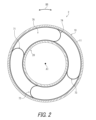
- FIG. 2 is a cross-sectional view of the rotary connector device shown in FIG.
- FIG. 3 is a perspective view of the lead block.
- FIG. 4 is a front view of the lead block.
- FIG. 5 is a rear view of the lead block.
- FIG. 6 is a perspective view of the first bus bar and the second bus bar excluding the lead block body.
- FIG. 7 is a rear view of the first bus bar and the second bus bar excluding the lead block body.
- FIG. 8 is a side view of the first bus bar and the second bus bar excluding the lead block body.
- FIG. 9 is an enlarged view of the side surface of the first conductor connection portion and the first cut surface as viewed from the second direction.
- FIG. 9 is an enlarged view of the side surface of the first conductor connection portion and the first cut surface as viewed from the second direction.
- FIG. 10 is an enlarged view of a side surface of the second conductor connection portion as viewed from a second direction and a second cut surface.
- FIG. 11 is a cross-sectional view of the lead block taken along line IX-IX in FIGS.
- FIG. 12 is a flowchart showing a method for manufacturing the lead block shown in FIG.
- FIG. 13 is a plan view showing the cutting step shown in FIG.
- FIG. 14 is a diagram for explaining the fixing step by the first and second clamps in FIG.
- the rotary connector device 2 includes a stator 10 and a rotator 20.
- the rotator 20 is rotatable about a rotation axis A1 relative to the stator 10.
- the stator 10 is configured to be attached to a vehicle body.
- the rotator 20 is configured to be connected to a steering wheel.
- the rotary connector device 2 includes a lead block 30. At least one of the stator 10 and the rotator 20 includes a connector holder 50. The lead block 30 can be attached to the connector holder 50.
- the connector holder 50 includes a first connector holder 51 and a second connector holder 52 that is different from the first connector holder 51.
- the second connector holder 52 is positioned away from the first connector holder 51.
- the stator 10 includes the first connector holder 51.
- the rotator 20 includes the second connector holder 52.
- the rotary connector device 2 includes a third electrical connector 60.
- the rotary connector device 2 includes a plurality of third electrical connectors 60.
- the third electrical connector 60 attached to the stator 10 may also be referred to as the third electrical connector 60A.
- the third electrical connector 60 attached to the rotator 20 may also be referred to as the third electrical connector 60B.
- the total number of third electrical connectors 60 is not limited to two.
- the third electrical connector 60 may be omitted from the rotary connector device 2. At least one of the third electrical connectors 60A and 60B may be omitted from the rotary connector device 2.
- the rotating connector device 2 includes a fourth electrical connector 62.
- the rotating connector device 2 includes a plurality of fourth electrical connectors 62.
- the fourth electrical connector 62 attached to the stator 10 may also be referred to as the fourth electrical connector 62A.
- the fourth electrical connector 62 attached to the rotator 20 may also be referred to as the fourth electrical connector 62B.
- the total number of fourth electrical connectors 62 is not limited to two.
- the fourth electrical connector 62 may be omitted from the rotating connector device 2. At least one of the fourth electrical connectors 62A and 62B may be omitted from the rotating connector device 2.
- the stator 10 includes a third connector holder 53.
- the third electrical connector 60A is attachable to the third connector holder 53.
- the fourth electrical connector 62A is attachable to the third connector holder 53.
- the stator 10 and the rotator 20 form a cable accommodating space 70 that is arranged to surround the rotation axis A1.
- the cable accommodating space 70 is annular and extends in the circumferential direction D5 with respect to the rotation axis A1.
- the rotating connector device 2 includes electrical cables 71, 72, 73, and 74.
- the electrical cables 71, 72, 73, and 74 are flexible. Examples of the electrical cables 71, 72, 73, and 74 include flexible flat cables.
- a first end of the electrical cable 71 is electrically connected to the first electrical connector 29A (see FIG. 1).
- a second end of the electrical cable 71 (first conductor 71A described below) is electrically connected to the lead block 30 (see FIG. 1).
- the electrical cable 71 electrically connects the first electrical connector 29A and the lead block 30 (see FIG. 1).
- the first electrical connector 29A can be attached to the first connector holder 51.
- a first end of the electrical cable 72 is electrically connected to the second electrical connector 49A (see FIG. 1).
- a second end of the electrical cable 72 (a second conductor 72A described below) is electrically connected to the lead block 30 (see FIG. 1).
- the electrical cable 72 electrically connects the second electrical connector 49A and the lead block 30 (see FIG. 1).
- the second electrical connector 49A can be attached to the first connector holder 51.
- a first end of the electrical cable 73 is electrically connected to the third electrical connector 60A (see FIG. 1).
- a second end of the electrical cable 73 is electrically connected to the third electrical connector 60B (see FIG. 1).
- the electrical cable 73 electrically connects the third electrical connectors 60A and 60B (see FIG. 1).
- a first end of the electrical cable 74 is electrically connected to the fourth electrical connector 62A (see FIG. 1).
- a second end of the electrical cable 74 is electrically connected to the fourth electrical connector 62B (see FIG. 1).
- the electrical cable 74 electrically connects the fourth electrical connectors 62A and 62B (see FIG. 1).
- the lead block 30 includes a lead block body 31, a first bus bar 32A, and a second bus bar 32B.
- the lead block body 31 includes an electrically insulating material.
- the first bus bar 32A and the second bus bar 32B are partially provided within the lead block body 31 and include a conductive material.
- the first bus bar 32A includes a first connection pin 33A, a first conductor connection portion 34A, and a first intermediate portion 35A.
- the second bus bar 32B includes a second connection pin 33B, a second conductor connection portion 34B, and a second intermediate portion 35B.
- the first connection pin 33A is exposed from the lead block body 31 and can be electrically connected to the connector CNT (see FIG. 3) of the external electric cable EXT.
- the second connection pin 33B is exposed from the lead block body 31 and can be electrically connected to the connector CNT (see FIG. 3) of the external electric cable EXT.
- the first connection pin 33A and the second connection pin 33B are aligned in the first direction D1.
- the first connection pin 33A and the second connection pin 33B protrude from the lead block body 31 in the second direction D2 perpendicular to the first direction D1.
- the first conductor connection portion 34A is exposed from the lead block body 31 so as to be electrically connected to the first conductor 71A of the electric cable 71.
- the second conductor connection portion 34B is exposed from the lead block body 31 so as to be electrically connected to the second conductor 72A of the electric cable 72.
- the first conductor connection portion 34A and the second conductor connection portion 34B are arranged spaced apart in the second direction D2.
- the first conductor connection portion 34A includes a first main body portion 36A, a first connection portion 37A, a first cut surface 38A, a first protrusion 39A, and a third protrusion 40A.
- the second conductor connection portion 34B includes a second main body portion 36B, a second connection portion 37B, a second cut surface 38B, a second protrusion 39B, and a fourth protrusion 40B.
- the first body portion 36A includes a first exposed surface 36AP and a third exposed surface 36AQ.
- the second body portion 36B includes a second exposed surface 36BP and a fourth exposed surface 36BQ.
- the first exposed surface 36AP, the second exposed surface 36BP, the third exposed surface 36AQ, and the fourth exposed surface 36BQ face the first direction D1.
- the first exposed surface 36AP, the second exposed surface 36BP, the third exposed surface 36AQ, and the fourth exposed surface 36BQ are each substantially flat, and the normal direction thereof is substantially the first direction D1.
- the third exposed surface 36AQ is provided on the back side of the first exposed surface 36AP in the first direction D1.
- the fourth exposed surface 36BQ is provided on the back side of the second exposed surface 36BP in the first direction D1.
- the first exposed surface 36AP and the second exposed surface 36BP are exposed from the lead block body 31 when viewed from the first direction D1.
- the first connection portion 37A is provided on the first exposed surface 36A and configured to be electrically connected to the first conductor 71A of the electric cable 71.
- the first connection portion 37A may also be provided on the third exposed surface 36AQ.
- the second connection portion 37B is provided on the second exposed surface 36B and configured to be electrically connected to the second conductor 72A of the electric cable 72.
- the second connection portion 37B may also be provided on the fourth exposed surface 36BQ.
- the first protrusion 39A protrudes in the second direction D2 from the first body portion 36A toward the second conductor connection portion 34B.
- the second protrusion 39B protrudes in the second direction D2 from the second body portion 36B toward the first conductor connection portion 34A.
- the first protrusion 39A has a width W3 narrower than the width W1 of the first body portion 36A in a third direction D3 perpendicular to the first direction D1 and the second direction D2.
- the second protrusion 39B has a width W3 narrower than the width W2 of the second body portion 36B in the third direction D3.
- the first protrusion 39A has a first cut surface 38A.
- the second protrusion 39B has a second cut surface 38B.
- the first cut surface 38A faces toward the second conductor connection portion 34B. More specifically, the first cut surface 38A faces toward the second cut surface 38B in the second direction D2.
- the second cutting surface 38B faces the first cutting surface 38A and is spaced apart from the first cutting surface 38A.
- the third protrusion 40A protrudes in the third direction D3 from the first body 36A.
- the length L3 in the second direction D2 of the third protrusion 40A is shorter than the length L1 in the second direction D2 of the first body 36A.
- the fourth protrusion 40B protrudes in the third direction D3 from the second body 36B.
- the length L4 in the second direction D2 of the fourth protrusion 40B is shorter than the length L2 in the second direction D2 of the second body 36B. Since the third protrusion 40A and the fourth protrusion are gripped by the lead block body 31, the first conductor connection portion 34A and the second conductor connection portion 34B are firmly held by the lead block body 31.
- the third protrusion 40A and the fourth protrusion 40B can be used as a runner when punching.
- FIGS. 6 to 8 show the first bus bar 32A and the second bus bar 32B excluding the lead block body 31.
- the first intermediate portion 35A connects the first connection pin 33A to the first conductor connection portion 34A.
- the second intermediate portion 35B connects the second connection pin 33B to the second conductor connection portion 34B.
- the first bus bar 32A is disposed so as to at least partially overlap with the second bus bar 32B when viewed from the first direction D1.
- the overlapping portion is indicated by hatching.
- the first connection pin 33A overlaps with the second connection pin 33B when viewed from the first direction D1.
- the first intermediate portion 35A partially overlaps with the second body portion 36B when viewed from the first direction D1.
- the first intermediate portion 35A has a first width WM1 defined in a third direction D3 perpendicular to the first direction D1 and the second direction D2.
- the first connection pin 33A has a first pin width WP1 defined in the third direction D3.
- the first width WM1 is greater than the first pin width WP1.
- the second intermediate portion 35B has a second width WM2 defined in a third direction D3 perpendicular to the first direction D1 and the second direction D2.
- the second connection pin 33B has a second pin width WP2 defined in the third direction D3.
- the second width WM2 is greater than the second pin width WP2.
- the first bus bar 32A includes a bent portion 41 that is connected to the first conductor connection portion 34A and is bent from the first conductor connection portion 34A in the first direction D1.
- the bent portion 41 is provided between the first conductor connection portion 34A and the first intermediate portion 35A.
- the bent portion 41 is bent approximately 90 degrees at a portion adjacent to the first conductor connection portion 34A, and is bent approximately 90 degrees at a portion adjacent to the first intermediate portion 35A.
- the first conductor connection portion 34A includes a first conductor connection portion side surface 34AS.
- the first conductor connection portion side surface 34AS connects the first exposed surface 36AP and the third exposed surface 36AQ.
- the second conductor connection portion 34B includes a second conductor connection portion side surface 34BS.
- the second conductor connection portion side surface 34BS connects the second exposed surface 36BP and the fourth exposed surface 36BQ.
- the first cut surface 38A is a surface formed when a cut piece 43 (see FIG. 13) of the connecting portion 39 is cut from the bent bar body 32 during the manufacture of the lead block 30.
- the first conductor connection portion side surface 34AS is a surface formed by, for example, pressing (e.g., shearing), whereas the first cut surface 38A is a surface formed by a process different from that of the first conductor connection portion side surface 34AS.
- the first cut surface 38A is a surface formed by, for example, pressing (e.g., shearing) in the same manner as the first conductor connection portion side surface 34AS.
- first conductor connection portion side surface 34AS includes shear surface 34AC and fracture surface 34AD.
- Fracture surface 34AD is adjacent to shear surface 34AC in first direction D1.
- Shear surface 34AC is a surface formed when material is sheared by the punch and die during shearing, and includes multiple streaks extending in one direction (e.g., first direction D1).
- Fracture surface 34AD is a surface formed when part of the material is sheared by the punch and die during shearing, and then fractured, and includes fine irregularities.
- the appearance of shear surface 34AC differs from the appearance of fracture surface 34AD.
- the first cut surface 38A includes a first shear surface 38AC and a first fracture surface 38AD.
- the first shear surface 38AC is adjacent to the first shear surface 38AC in the first direction D1.
- the first shear surface 38AC is a surface formed by shearing the material with the punch and die during shearing, and includes multiple streaks extending in one direction (e.g., the first direction D1).
- the first fracture surface 38AD is a surface formed by breaking after a portion of the material is sheared with the punch and die during shearing, and includes fine irregularities. Therefore, the appearance of the first shear surface 38AC is different from the appearance of the first fracture surface 38AD.
- the length of the first shear surface 38AC in the first direction D1 is different from the length of the shear surface 34AC in the first direction D1.
- the length of the first fracture surface 38AD in the first direction D1 is different from the length of the fracture surface 34AD in the first direction D1. Therefore, the appearance of the first cut surface 38A is different from the appearance of the first conductor connection portion side surface 34AS.
- the first cut surface 38A may be a surface that has been surface-finished after the connecting portion 39 has been cut from the bar bent body 32.
- the first conductor connection portion side surface 34AS may be a surface that has been surface-finished.
- the appearance of the first cut surface 38A may be the same as the appearance of the first conductor connection portion side surface 34AS.
- the second cut surface 38B is a surface formed when a cut piece 43 (see FIG. 13, shown by dotted lines in FIGS. 6 to 8) of the connecting portion 39 is cut from the bent bar body 32 during the manufacture of the lead block 30.
- the second conductor connection portion side surface 34BS is a surface formed, for example, by pressing (e.g., shearing), whereas the second cut surface 38B is a surface formed in a process different from that of the second conductor connection portion side surface 34BS.
- the second cut surface 38B is a surface formed, for example, by pressing (e.g., shearing) in the same manner as the second conductor connection portion side surface 34BS.
- second conductor connection portion side surface 34BS includes shear surface 34BC and fracture surface 34BD.
- Fracture surface 34BD is adjacent to shear surface 34BC in first direction D1.
- Shear surface 34BC is a surface formed by shearing a material with a punch and die during shearing, and includes multiple streaks extending in one direction (e.g., first direction D1).
- Fracture surface 34BD is a surface formed by breaking a part of the material after it is sheared with a punch and die during shearing, and includes fine irregularities.
- the appearance of shear surface 34BC differs from the appearance of fracture surface 34BD.
- the second cut surface 38B includes a second shear surface 38BC and a second fracture surface 38BD.
- the second shear surface 38BC is adjacent to the second shear surface 38BC in the first direction D1.
- the second shear surface 38BC is a surface formed by shearing the material with the punch and die during shearing, and includes multiple streaks extending in one direction (e.g., the first direction D1).
- the second fracture surface 38BD is a surface formed by breaking after a portion of the material is sheared with the punch and die during shearing, and includes fine irregularities. Therefore, the appearance of the second shear surface 38BC is different from the appearance of the second fracture surface 38BD.
- the length of the second shear surface 38BC in the first direction D1 is different from the length of the shear surface 34BC in the first direction D1.
- the length of the second fracture surface 38BD in the first direction D1 is different from the length of the fracture surface 34BD in the first direction D1. Therefore, the appearance of the second cut surface 38B is different from the appearance of the second conductor connection portion side surface 34BS.
- the second cut surface 38B may be a surface that has been surface-finished after the connecting portion 39 has been cut from the bar bent body 32.
- the second conductor connection portion side surface 34BS may be a surface that has been surface-finished.
- the second cut surface 38B When the second cut surface 38B is surface-finished, the second shear surface 38BC and the second fracture surface 38BD are at least partially replaced by a finished surface.
- the shear surface 34BC and the fracture surface 34BD are at least partially replaced by a finished surface. Therefore, the appearance of the second cut surface 38B may be the same as the appearance of the second conductor connection portion side surface 34BS.
- the lead block body 31 has a first surface 31S1 facing the first direction D1 and a second surface 31S2 facing the first direction D1.
- the second surface 31S2 is provided on the rear side of the first surface 31S1 in the first direction D1.
- the lead block body 31 has a first opening 31H1 provided on the first surface 31S1.
- the lead block body 31 has two first openings 31H1.
- the two first openings 31H1 are shown as symbols 31H11 and 31H12 to distinguish them from each other.
- the first opening 31H11 and the first opening 31H12 have substantially the same shape.
- the lead block body 31 has a second opening 31H2 provided on the second surface 31S2.
- the lead block body 31 has two second openings 31H2.
- the two second openings 31H2 are distinguished from each other by the reference numerals 31H21 and 31H22.
- the second openings 31H21 and 31H22 have substantially the same shape.
- At least one of the first intermediate portion 35A and the second intermediate portion 35B is at least partially exposed from the first opening 31H1 when viewed from the first direction D1.
- the first intermediate portion 35A and the second intermediate portion 35B are at least partially exposed from the first opening 31H1 when viewed from the first direction D1.
- the first intermediate portion 35A and the second intermediate portion 35B are partially exposed from the first opening 31H1 when viewed from the first direction D1.
- the first intermediate portion 35A exposed from the first opening is disposed so as to at least partially overlap with the second intermediate portion 35B when viewed from the first direction D1.
- the first intermediate portion 35A exposed from the first opening is disposed so as to partially overlap with the second intermediate portion 35B when viewed from the first direction D1.
- At least one of the first intermediate portion 35A and the second intermediate portion 35B is at least partially exposed from the second opening 31H2 when viewed from the first direction D1.
- the first intermediate portion 35A is at least partially exposed from the second opening 31H2 when viewed from the first direction D1.
- the first intermediate portion 35A is partially exposed from the second opening 31H2 when viewed from the first direction D1.
- the second intermediate portion 35B is not exposed from the second opening 31H2 when viewed from the first direction D1.
- the lead block body 31 has a through hole TH that is disposed between the first cut surface 38A and the second cut surface 38B when viewed from the first direction D1 and that penetrates to the second cut surface 38B.
- the through hole TH is defined by a substantially O-shaped rib 42.
- the lead block body 31 has a third opening 31H3 and a fourth opening 31H4.
- the third opening 31H3 and the fourth opening 31H4 sandwich the rib 42 when viewed from the first direction D1 and penetrate the lead block body 31 in the first direction D1.
- the third exposed surface 36AQ is exposed from the third opening 31H3 when viewed from the first direction D1.
- the fourth exposed surface 36BQ is exposed from the fourth opening 31H4 when viewed from the first direction D1.
- the manufacturing method of the lead block 30 includes a step S1 of preparing a flat plate 100 that contains a conductive material and has a vertical direction DL, a horizontal direction DW, and a thickness direction DT that are perpendicular to each other.
- the manufacturing method further includes a cutting step S2 of punching out a bar assembly 110 from the flat plate 100.
- the bar assembly 110 has a first bus bar 32A including a first connection pin 33A, a first conductor connection portion 34A, a first intermediate portion 35A, and a bent portion 41, a second bus bar 32B including a second connection pin 33B, a second conductor connection portion 34B, and a second intermediate portion 35B, and a connecting portion 39.
- the first connection pin 33A extends in the vertical direction DL.
- the bent portion 41 extends in the horizontal direction DW from the first conductor connection portion 34A.
- the first intermediate portion 35A extends in the vertical direction DL from the bent portion 41 and connects to the first connection pin 33A.
- the second connection pin 33B extends in the vertical direction DL.
- the second intermediate portion 35B connects the second connection pin 33B and the second conductor connection portion 34B, and extends in the vertical direction DL.
- the connecting portion 39 connects the first conductor connection portion 34A and the second conductor connection portion 34B, and has a width in the horizontal direction DW that is shorter than the width in the horizontal direction DW of the first conductor connection portion 34A and the width in the horizontal direction DW of the second conductor connection portion 34B.
- the first connection pin 33A and the second connection pin 33B are arranged in the horizontal direction DW, and the first conductor connection portion 34A, the connecting portion 39, and the second conductor connection portion 34B are arranged in the vertical direction DL.
- the bar assembly 110 is formed so that the distance in the horizontal direction DW between the first connection pin 33A and the second connection pin 33B, the distance in the horizontal direction DW between the first intermediate portion 35A and the second intermediate portion 35B, and the distance in the vertical direction DL between the bent portion 41 and the second conductor connection portion 34B are all less than the distance in the vertical direction DL of the connecting portion 39.
- the manufacturing method of the lead block 30 includes a bending process S3 in which the bent portion 41 of the bar assembly 110 is bent in the thickness direction DT to form the bar bent body 32 (see Figures 6 to 8).
- the first intermediate portion 35A and the second intermediate portion 35B overlap in part when viewed in the first direction D1 in which the first connection pin 33A and the second connection pin 33B are aligned.
- the manufacturing method of the lead block 30 includes a molding step S4 of embedding the bar bent body 32 in the lead block main body 31 by insert molding.
- the molding step S4 includes a step S41 of placing the bar bent body 32 in a mold that exposes to the outside at least a part of the connecting portion 39, a first overlapping portion (hatched portion in FIG. 7) of the first intermediate portion 35A that overlaps with the second intermediate portion 35B in the first direction D1, a first non-overlapping portion of the first intermediate portion 35A adjacent to the first overlapping portion (portion not hatched by the first intermediate portion 35A in FIG. 7), and a part of the second intermediate portion 35B.
- the molding step S4 includes a step S41 of placing the bar bent body 32 in a mold that exposes to the outside at least a part of the connecting portion 39.
- molding process S4 includes a step S42 of fixing a part of second intermediate portion 35B and first non-overlapping portion 35A1 with first presser 45. Molding process S4 includes a step S43 of fixing first overlapping portion 35A2 and first non-overlapping portion 35A1 with second presser 46.
- First presser 45 occupies the area where first opening 31H1 will be formed after molding.
- Second presser 46 occupies the area where second opening 31H2 will be formed after molding.
- First bus bar 32A is bent and therefore requires significant adjustment of positioning and posture, whereas second bus bar 32B is not bent and therefore does not require as much adjustment of positioning and posture.
- the alignment of the first bus bar 32A is adjusted by sandwiching the first intermediate portion 35A between the first presser 45 and the second presser 46, while the second intermediate portion 35B is supported by the first presser 45, reducing the amount of resin used in molding and making the lead block 30 more compact.
- the molding process S4 includes a process S44 of pouring a resin containing an electrically insulating material into a mold, and a process S45 of molding the lead block body 31 by removing the mold, the first pressure member 45, and the second pressure member 46.
- the manufacturing method of the lead block 30 includes a step S5 of cutting the connecting portion 39 to electrically insulate the first bus bar 32A from the second bus bar 32B. More specifically, in step S5, a cut piece 43 (see FIG. 13) of the connecting portion 39 is cut, and the remaining connecting portion 39 forms the first protruding portion 39A and the second protruding portion 39B. In this manner, the lead block 30 is manufactured.
- the lead block 30 includes a lead block body 31, a first bus bar 32A, and a second bus bar 32B.
- the lead block body 31 includes an electrically insulating material.
- the first bus bar 32A and the second bus bar 32B are partially provided within the lead block body 31 and include a conductive material.
- the first bus bar 32A includes a first connection pin 33A exposed from the lead block body 31 and electrically connectable to the connector CNT of the external electric cable EXT, and a first conductor connection portion 34A exposed from the lead block body 31 so as to be electrically connected to the first conductor 71A of the electric cable 71.
- the second bus bar 32B includes a second connection pin 33B exposed from the lead block body 31 and electrically connectable to the connector CNT of the external electric cable EXT, and a second conductor connection portion 34B exposed from the lead block body 31 so as to be electrically connected to the second conductor 72A of the electric cable 72.
- the first connection pin 33A and the second connection pin 33B are aligned in the first direction D1.
- the first conductor connection portion 34A includes a first exposed surface 36AP facing the first direction D1, a first connection portion 37A provided on the first exposed surface 36AP and configured to be electrically connected to the first conductor 71A of the electric cable 71, and a first cut surface 38A facing the second conductor connection portion 34B.
- the second conductor connection portion 34B includes a second exposed surface 36BP facing the first direction D1, a second connection portion 37B provided on the second exposed surface 36BP and configured to be electrically connected to the second conductor 72A of the electric cable 72, and a second cut surface 38B facing the first cut surface 38A and spaced apart from the first cut surface 38A.
- the first conductor connection portion 34A and the second conductor connection portion 34B are exposed in the same direction as the arrangement direction of the first connection pin 33A and the second connection pin 33B, and the first connection pin 33A and the second connection pin 33B are not located on the same plane. Therefore, the first bus bar 32A is bent between the first conductor connection portion 34A and the first connection pin 33A, but since the first conductor connection portion 34A and the second conductor connection portion 34B are on the same plane, the first bus bar 32A and the second bus bar 32B can be easily positioned relative to the lead block body 31 based on the first conductor connection portion 34A and the second conductor connection portion 34B.
- the manufacturing method of the lead block 30 includes preparing a flat plate 100 made of a conductive material and having a vertical direction DL, a horizontal direction DW, and a thickness direction DT that are perpendicular to each other.
- the manufacturing method includes preparing a first bus bar 32A including a first connection pin 33A extending in the vertical direction DL and electrically connectable to a connector CNT of the external electric cable EXT, a first conductor connection portion 34A configured to electrically connect to a first conductor 71A of the electric cable 71, a bent portion 41 extending in the horizontal direction DW from the first conductor connection portion 34A, and a first intermediate portion 35A extending from the bent portion 41 in the vertical direction DL and connecting the first connection pin 33A and the first conductor connection portion 34A, a second connection pin 33B extending in the vertical direction DL and electrically connectable to a connector CNT of the external electric cable EXT, and a first intermediate portion 35A electrically connectable to a second conductor 72A
- the method includes punching out from the flat plate 100 a bar assembly 110 having a second conductor connection portion 34B configured to connect the second connection pin 33B and the second conductor connection portion 34B to each other, a second bus bar 32B including a second intermediate portion 35B connecting the second connection pin 33B and the second conductor connection portion 34B and extending in the vertical direction DL, and a connecting portion 39 connecting the first conductor connection portion 34A and the second conductor connection portion 34B and having a width in the horizontal direction DW shorter than the width in the horizontal direction DW of the first conductor connection portion 34A and the width in the horizontal direction DW of the second conductor connection portion 34B, the first connection pin 33A and the second connection pin 33B being arranged in the horizontal direction DW, and the first conductor connection portion 34A, the connecting portion 39, and the second conductor connection portion 34B being arranged in the vertical direction DL.
- the manufacturing method includes bending the bent portion 41 of the bar assembly 110 in the thickness direction DT to form a bar folded body 32.
- the manufacturing method includes placing the bent bar body 32 in a mold that exposes at least a portion of the connecting portion 39 to the outside, and molding the lead block body 31 with a resin that contains an electrically insulating material.
- the manufacturing method also includes cutting the connecting portion 39 to electrically insulate the first bus bar 32A and the second bus bar 32B.
- the connecting portion 39 is cut after the lead block body 31 is molded, making it easy to mold and allowing for precise alignment of the first bus bar 32A and the second bus bar 32B.
- the lead block 30 includes a lead block main body 31, a first bus bar 32A, and a second bus bar 32B.
- the lead block main body 31 includes an electrically insulating material.
- the first bus bar 32A and the second bus bar 32B are partially provided within the lead block main body 31 and include a conductive material.
- the first bus bar 32A includes a first connection pin 33A exposed from the lead block main body 31 and electrically connectable to the connector CNT of the external electrical cable EXT, a first conductor connection portion 34A exposed from the lead block main body so as to be electrically connected to the first conductor 71A of the electrical cable 71, and a first intermediate portion 35A connecting the first connection pin 33A and the first conductor connection portion 34A.
- the second bus bar 32B includes a second connection pin 33B exposed from the lead block body 31 and electrically connectable to the connector CNT of the external electric cable EXT, a second conductor connection portion 34B exposed from the lead block body 31 to be electrically connected to the second conductor 72A of the electric cable 72, and a second intermediate portion 35B connecting the second connection pin 33B and the second conductor connection portion 34B.
- the first connection pin 33A and the second connection pin 33B are aligned in the first direction D1.
- the first conductor connection portion 34A includes a first exposed surface 34AP facing the first direction D1, and a first connection portion 37A provided on the first exposed surface 34AP and configured to be electrically connected to the first conductor 71A of the electric cable 71.
- the second conductor connection portion 34B includes a second exposed surface 34BP facing the first direction D1, and a second connection portion 37B provided on the second exposed surface 34BP and configured to electrically connect the second conductor 72A of the electric cable 72.
- the lead block body 31 has a first opening 31H1. At least one of the first intermediate portion 35A and the second intermediate portion 35B is at least partially exposed from the first opening 31H1 when viewed from the first direction D1.
- a jig can be attached to the first opening 31H1 to fix at least one of the first intermediate portion 35A and the second intermediate portion 35B, improving the alignment accuracy.
- the manufacturing method of the lead block 30 includes preparing a flat plate 100 made of a conductive material and having a vertical direction DL, a horizontal direction DW, and a thickness direction DT that are perpendicular to each other.
- the manufacturing method includes preparing a first bus bar 32A including a first connection pin 33A extending in the vertical direction DL and electrically connectable to a connector CNT of the external electric cable EXT, a first conductor connection portion 34A electrically connecting to a first conductor 71A of the electric cable 71, a bent portion 41 extending in the horizontal direction DW from the first conductor connection portion 34A, and a first intermediate portion 35A extending from the bent portion 41 in the vertical direction DL and connecting to the first connection pin 33A, a second connection pin 33B extending in the vertical direction DL and electrically connectable to the connector CNT of the external electric cable EXT, and a second conductor connection portion 34A electrically connecting to a second conductor 72A of the electric cable 72.
- the second bus bar 32B including a connecting portion 34B, a second intermediate portion 35B connecting the second connection pin 33B and the second conductor connection portion 34B and extending in the vertical direction DL, and a connecting portion 39 connecting the first conductor connection portion 34A and the second conductor connection portion 34B and having a width in the horizontal direction DW shorter than the width in the horizontal direction DW of the first conductor connection portion 34A and the width in the horizontal direction DW of the second conductor connection portion 34B, wherein the first connection pin 33A and the second connection pin 33B are aligned in the horizontal direction DW, and the first conductor connection portion 34A, the connecting portion 39, and the second conductor connection portion 34B are aligned in the vertical direction DL, from the flat plate 100.
- the manufacturing method includes bending the bent portion 41 of the bar assembly 110 in the thickness direction DT to form a bent bar body 32 in which the first intermediate portion 35A and the second intermediate portion 35B are overlapped in part when viewed in a first direction D1 in which the first connection pin 33A and the second connection pin 33B are aligned.
- the manufacturing method includes placing the bent bar body 32 in a mold that exposes to the outside at least a part of the connecting portion 39, a first overlapping portion 35A2 that overlaps the second intermediate portion 35B of the first intermediate portion 35A in the first direction D1, a first non-overlapping portion 35A1 of the first intermediate portion 35A adjacent to the first overlapping portion 35A2, and a part of the second intermediate portion 35B.
- the manufacturing method includes fixing a part of the second intermediate portion and the first non-overlapping portion 35A1 with a first presser 45.
- the manufacturing method includes fixing the first overlapping portion 35A2 and the first non-overlapping portion 35A1 by the second presser 46 on the opposite side of the first presser 45 in the first direction D1.
- the manufacturing method includes pouring a resin containing an electrically insulating material into a mold, and molding the lead block body 31 by removing the mold, the first presser 45, and the second presser 46.
- the manufacturing method includes cutting the connecting portion 39 to electrically insulate the first bus bar 32A and the second bus bar 32B.
- the first bus bar 32A and the second bus bar 32B are fixed by two clamps 45, 46 when the lead block body 31 is molded, and are removed after molding, making it easy to mold the lead block body 31 and enabling precise alignment of the first bus bar 32A and the second bus bar 32B.
- ordinal numbers such as “first” and “second” are simply terms for identifying configurations and have no other meaning (such as a particular order). For example, the presence of a “first element” does not imply the presence of a “second element,” and the presence of a “second element” does not imply the presence of a "first element.”
- the expression "at least one of A and B” in this disclosure includes, for example, any of (1) A only, (2) B only, and (3) both A and B.
- the expression "at least one of A, B, and C” includes, for example, any of (1) A only, (2) B only, (3) C only, (4) A and B, (5) B and C, (6) A and C, and (7) all of A, B, and C.
- the expression "at least one of A and B" is not to be interpreted as "at least one of A and at least one of B.”
- Rotary connector device 10 Stator 20: Rotator 30: Lead block 31: Lead block body 31H1: First opening 31H2: Second opening 31H3: Third opening 31H4: Fourth opening 31S1: First surface 31S2: Second surface 32: Bar bent body 32A: First bus bar 32B: Second bus bar 33A: First connection pin 33B: Second connection pin 34A: First conductor connection portion 34B: Second conductor connection portion 34BP: Second exposed surface 35A: First intermediate portion 35A1: First non-overlapping portion 35A2: First overlapping portion 35B: Second intermediate portion 36A: First main body portion 36AP: First exposed surface 36AQ: Third exposed surface 36B: Second main body portion 36BP : second exposed surface 36BQ : fourth exposed surface 37A : first connecting portion 37B : second connecting portion 38A : first cut surface 38B : second cut surface 39 : coupling portion 39A : first protruding portion 39B : second protruding portion 40A : third protruding portion 40B : fourth protruding portion 41
Landscapes
- Engineering & Computer Science (AREA)
- Manufacturing & Machinery (AREA)
- Mechanical Engineering (AREA)
- Coupling Device And Connection With Printed Circuit (AREA)
Abstract
Description
このようにして、リードブロック30が製造される。
10 :ステータ
20 :ロテータ
30 :リードブロック
31 :リードブロック本体
31H1 :第1開口
31H2 :第2開口
31H3 :第3開口
31H4 :第4開口
31S1 :第1面
31S2 :第2面
32 :バー折り曲げ体
32A :第1バスバー
32B :第2バスバー
33A :第1接続ピン
33B :第2接続ピン
34A :第1導体接続部
34B :第2導体接続部
34BP :第2露出面
35A :第1中間部
35A1 :第1非重畳部分
35A2 :第1重畳部分
35B :第2中間部
36A :第1本体部
36AP :第1露出面
36AQ :第3露出面
36B :第2本体部
36BP :第2露出面
36BQ :第4露出面
37A :第1接続部
37B :第2接続部
38A :第1切断面
38B :第2切断面
39 :連結部
39A :第1突出部
39B :第2突出部
40A :第3突出部
40B :第4突出部
41 :折り曲げ部
45 :第1押さえ
46 :第2押さえ
71 :電気ケーブル
71A :第1導体
72 :電気ケーブル
72A :第2導体
100 :平板
110 :バー集合体
A1 :回転軸線
CNT :コネクタ
D1 :第1方向
D2 :第2方向
D3 :第3方向
DL :縦方向
DT :厚さ方向
DW :横方向
EXT :外部電気ケーブル
WM1 :第1幅
WM2 :第2幅
WP1 :第1ピン幅
WP2 :第2ピン幅
Claims (27)
- 電気絶縁材料を含むリードブロック本体と、
部分的に前記リードブロック本体内に設けられ導電材料を含む第1バスバー及び第2バスバーと、を備え、
前記第1バスバーは、前記リードブロック本体から露出し外部電気ケーブルのコネクタと電気的に接続可能な第1接続ピンと、電気ケーブルの第1導体に電気的に接続されるように前記リードブロック本体から露出する第1導体接続部と、を含み、
前記第2バスバーは、前記リードブロック本体から露出し前記外部電気ケーブルの前記コネクタと電気的に接続可能な第2接続ピンと、前記電気ケーブルの第2導体に電気的に接続されるように前記リードブロック本体から露出する第2導体接続部と、を含み、
前記第1接続ピンと前記第2接続ピンとは、第1方向に並び、
前記第1導体接続部は、前記第1方向を向く第1露出面と、前記第1露出面上に設けられ前記電気ケーブルの前記第1導体に電気的に接続されるように構成される第1接続部と、を含み、
前記第2導体接続部は、前記第1方向を向く第2露出面と、前記第2露出面上に設けられ前記電気ケーブルの前記第2導体が電気的に接続されるように構成される第2接続部と、を含む、
リードブロック。
- 前記第1導体接続部と前記第2導体接続部とは、前記第1方向に垂直な第2方向に離間して配置される、
請求項1に記載のリードブロック。
- 前記第1導体接続部は、前記第1露出面を含む第1本体部と、前記第1本体部から前記第2導体接続部に向けて前記第2方向に突出する第1突出部と、を有し、
前記第2導体接続部は、前記第2露出面を含む第2本体部と、前記第2本体部から前記第1導体接続部に向けて前記第2方向に突出する第2突出部と、を有する、
請求項2に記載のリードブロック。
- 前記第1突出部は、前記第1方向且つ前記第2方向に垂直な第3方向において前記第1本体部の幅よりも狭い幅を有し、
前記第2突出部は、前記第3方向において前記第2本体部の幅よりも狭い幅を有する、
請求項3に記載のリードブロック。
- 前記第1突出部は、第1切断面を有し、
前記第2突出部は、第2切断面を有する、
請求項4に記載のリードブロック。
- 前記第1導体接続部は、前記第2導体接続部の方を向く第1切断面をさらに含み、
前記第2導体接続部は、前記第1切断面の方を向き前記第1切断面と離間して配置される第2切断面をさらに含む、
請求項1に記載のリードブロック。
- 前記第1接続ピンおよび前記第2接続ピンは、前記リードブロック本体から前記第2方向に突出する、
請求項1から6のいずれか1項に記載のリードブロック。
- 前記第1バスバーは、前記第1方向から見た場合に前記第2バスバーと少なくとも部分的に重畳するように配置される、
請求項1から6のいずれか1項に記載のリードブロック。
- 前記リードブロック本体は、前記第1方向から見た場合に前記第1切断面と前記第2切断面との間に配置され前記第1方向に貫通する貫通孔を有する、
請求項1から6のいずれか1項に記載のリードブロック。
- 前記第1導体接続部は、前記第1方向において前記第1露出面の裏側に設けられる第3露出面を有し、
前記第2導体接続部は、前記第1方向において前記第2露出面の裏側に設けられる第4露出面を有し、
前記リードブロック本体は、第3開口及び第4開口を有し、
前記第1露出面と前記第2露出面は、前記第1方向から見た場合に前記リードブロック本体から露出し、
前記第3露出面は、前記第1方向から見た場合に第3開口から露出し、
前記第4露出面は、前記第1方向から見た場合に第4開口から露出する、
請求項1から6のいずれか1項に記載のリードブロック。
- 前記第1バスバーは、前記第1導体接続部に連結され前記第1導体接続部から前記第1方向に向けて折り曲げられた折り曲げ部をさらに含む、
請求項1から6のいずれか1項に記載のリードブロック。
- 前記第1バスバーは、前記第1接続ピンと前記第1導体接続部とを連結する第1中間部をさらに含み、
前記第2バスバーは、前記第2接続ピンと前記第2導体接続部とを連結する第2中間部をさらに含み、
前記リードブロック本体は、第1開口を有し、
前記第1中間部および前記第2中間部の少なくとも1つは、前記第1方向から見た場合に少なくとも部分的に前記第1開口から露出する、
請求項1に記載のリードブロック。
- 前記リードブロック本体は、前記第1方向を向く第1面と、前記第1方向を向く第2面と、を有し、
前記第2面は、前記第1方向において前記第1面の裏側に設けられ、
前記第1開口は、前記第1面上に設けられる、
請求項12に記載のリードブロック。
- 前記リードブロック本体は、前記第2面上に設けられる第2開口を有し、
前記第1中間部および前記第2中間部の少なくとも1つは、前記第1方向から見た場合に少なくとも部分的に前記第2開口から露出する、
請求項13に記載のリードブロック。
- 前記第1中間部および前記第2中間部は、前記第1方向から見た場合に少なくとも部分的に前記第1開口から露出する、
請求項12に記載のリードブロック。
- 前記第1中間部は、前記第1方向から見た場合に少なくとも部分的に前記第2開口から露出し、
前記第2中間部は、前記第1方向から見た場合に前記第2開口から露出しない、
請求項14に記載のリードブロック。
- 前記第1導体接続部と前記第2導体接続部とは、前記第1方向に垂直な第2方向に離間して配置される、
請求項12に記載のリードブロック。
- 前記第1中間部は、前記第1方向および前記第2方向に垂直な第3方向に定義される第1幅を有し、
前記第1接続ピンは、前記第3方向に定義される第1ピン幅を有し、
前記第1幅は、前記第1ピン幅よりも大きい、
請求項17に記載のリードブロック。
- 前記第2中間部は、前記第1方向および前記第2方向に垂直な第3方向に定義される第2幅を有し、
前記第2接続ピンは、前記第3方向に定義される第2ピン幅を有し、
前記第2幅は、前記第2ピン幅よりも大きい、
請求項17に記載のリードブロック。
- 前記第1接続ピンおよび前記第2接続ピンは、前記リードブロック本体から前記第2方向に突出する、
請求項17に記載のリードブロック。
- 前記第1バスバーは、前記第1方向から見た場合に少なくとも部分的に前記第2バスバーと重畳するように配置される、
請求項12に記載のリードブロック。
- 前記第1開口から露出される前記第1中間部は、前記第1方向から見た場合に少なくとも部分的に前記第2中間部と重畳するように配置される、
請求項15に記載のリードブロック。
- 導電性材料から成り、互いに垂直な縦方向と横方向と厚さ方向とを有する平板を用意し、
前記縦方向に延び、外部電気ケーブルのコネクタと電気的に接続可能な第1接続ピンと、電気ケーブルの第1導体に電気的に接続するように構成される第1導体接続部と、前記第1導体接続部から前記横方向に延びる折り曲げ部と、前記折り曲げ部から縦方向に延び、前記第1接続ピンと前記第1導体接続部とを連結する第1中間部とを含む第1バスバーと、前記縦方向に延び、外部電気ケーブルのコネクタと電気的に接続可能な第2接続ピンと、電気ケーブルの第2導体に電気的に接続するように構成される第2導体接続部と、前記第2接続ピンと前記第2導体接続部とを連結し、前記縦方向に延びる第2中間部とを含む第2バスバーと、前記第1導体接続部と前記第2導体接続部とを連結し、前記第1導体接続部の前記横方向の幅及び前記第2導体接続部の前記横方向の幅よりも短い前記横方向の幅を有する連結部とを有し、前記第1接続ピンと前記第2接続ピンとが前記横方向に並び、前記第1導体接続部と前記連結部と前記第2導体接続部とが前記縦方向に並ぶように配置されたバー集合体を、前記平板から打ち抜き、
前記バー集合体を、前記折り曲げ部を前記厚さ方向に折り曲げてバー折り曲げ体を形成し、
前記連結部の少なくとも一部を外部に露出させる鋳型に前記バー折り曲げ体を入れて、電気絶縁材料を含む樹脂によってリードブロック本体を成型し、
前記連結部を切断して、前記第1バスバーと前記第2バスバーとを電気的に絶縁させる、
ことを含む、リードブロックの製造方法。
- 前記バー集合体は、
前記第1接続ピンと前記第2接続ピンとの前記横方向の距離、前記第1中間部と前記第2中間部との前記横方向の距離、及び、前記折り曲げ部と前記第2導体接続部との前記縦方向の距離は、いずれも、前記連結部の前記縦方向との距離以下となるように形成される、
ことを特徴とする、請求項23に記載の製造方法。
- 前記バー折り曲げ体は、前記第1接続ピンと前記第2接続ピンとが並ぶ第1方向に見て、前記第1中間部と前記第2中間部とがそれぞれの一部において重畳するように形成されており、
前記鋳型は、前記第1中間部の前記第2中間部と前記第1方向において重畳する第1重畳部分と、前記第1重畳部分と隣接する前記第1中間部の第1非重畳部分と、前記第2中間部の一部ともさらに外部に露出させ、
前記製造方法は、
前記第2中間部の一部と、前記第1非重畳部分を第1押さえによって固定し、
前記第1重畳部分と前記第1非重畳部分とを前記第1方向における前記第1押さえの反対側において第2押さえによって固定し、
前記鋳型に前記樹脂を流し込み、前記鋳型と前記第1押さえと前記第2押さえを除くことによって前記リードブロック本体を成型する、
ことをさらに含む、請求項23に記載のリードブロックの製造方法。
- ステータと、
前記ステータに対して回転軸線回りに回転可能に設けられるロテータと、
請求項1から6のいずれか1項または請求項12から22のいずれか1項に記載の前記リードブロックと、
前記リードブロックの前記第1接続部及び第2接続部に電気的に接続される前記電気ケーブルと、
を備える回転コネクタ装置。
- ステータと、
前記ステータに対して回転軸線回りに回転可能に設けられるロテータと、
請求項23から25のいずれか1項に記載の製造方法で製造された前記リードブロックと、
前記リードブロックの前記第1接続部及び第2接続部に電気的に接続される前記電気ケーブルと、
を備える回転コネクタ装置。
Priority Applications (4)
| Application Number | Priority Date | Filing Date | Title |
|---|---|---|---|
| KR1020257033753A KR20250163922A (ko) | 2023-03-15 | 2024-03-13 | 리드 블록, 회전 커넥터 장치 및 리드 블록의 제조 방법 |
| EP24770939.7A EP4683134A1 (en) | 2023-03-15 | 2024-03-13 | Lead block, rotary connector device, and method for manufacturing lead block |
| CN202480014938.0A CN120770101A (zh) | 2023-03-15 | 2024-03-13 | 引线块、旋转连接器装置以及引线块的制造方法 |
| US19/325,414 US20260011937A1 (en) | 2023-03-15 | 2025-09-10 | Lead block, rotary connector device, and lead block manufacturing method |
Applications Claiming Priority (4)
| Application Number | Priority Date | Filing Date | Title |
|---|---|---|---|
| JP2023-040784 | 2023-03-15 | ||
| JP2023040783A JP2024130853A (ja) | 2023-03-15 | 2023-03-15 | リードブロック、回転コネクタ装置、及び、リードブロックの製造方法 |
| JP2023-040783 | 2023-03-15 | ||
| JP2023040784A JP2024130854A (ja) | 2023-03-15 | 2023-03-15 | リードブロック、回転コネクタ装置、及び、リードブロックの製造方法 |
Related Child Applications (1)
| Application Number | Title | Priority Date | Filing Date |
|---|---|---|---|
| US19/325,414 Continuation US20260011937A1 (en) | 2023-03-15 | 2025-09-10 | Lead block, rotary connector device, and lead block manufacturing method |
Publications (1)
| Publication Number | Publication Date |
|---|---|
| WO2024190834A1 true WO2024190834A1 (ja) | 2024-09-19 |
Family
ID=92755315
Family Applications (1)
| Application Number | Title | Priority Date | Filing Date |
|---|---|---|---|
| PCT/JP2024/009827 Ceased WO2024190834A1 (ja) | 2023-03-15 | 2024-03-13 | リードブロック、回転コネクタ装置、及び、リードブロックの製造方法 |
Country Status (5)
| Country | Link |
|---|---|
| US (1) | US20260011937A1 (ja) |
| EP (1) | EP4683134A1 (ja) |
| KR (1) | KR20250163922A (ja) |
| CN (1) | CN120770101A (ja) |
| WO (1) | WO2024190834A1 (ja) |
Citations (5)
| Publication number | Priority date | Publication date | Assignee | Title |
|---|---|---|---|---|
| JP2000323253A (ja) | 1999-05-11 | 2000-11-24 | Alps Electric Co Ltd | 回転コネクタ |
| JP2009158169A (ja) * | 2007-12-25 | 2009-07-16 | Alps Electric Co Ltd | 回転コネクタ用リードブロックの製造方法 |
| JP2017147110A (ja) * | 2016-02-17 | 2017-08-24 | 古河電気工業株式会社 | 接続コネクタ、接続コネクタ付きフラットケーブル、及び回転コネクタ装置 |
| WO2021199746A1 (ja) * | 2020-03-31 | 2021-10-07 | 古河電気工業株式会社 | リードブロックおよび回転コネクタ装置 |
| WO2022260035A1 (ja) | 2021-06-11 | 2022-12-15 | 古河電気工業株式会社 | リードブロックおよび回転コネクタ装置 |
-
2024
- 2024-03-13 KR KR1020257033753A patent/KR20250163922A/ko active Pending
- 2024-03-13 EP EP24770939.7A patent/EP4683134A1/en active Pending
- 2024-03-13 CN CN202480014938.0A patent/CN120770101A/zh active Pending
- 2024-03-13 WO PCT/JP2024/009827 patent/WO2024190834A1/ja not_active Ceased
-
2025
- 2025-09-10 US US19/325,414 patent/US20260011937A1/en active Pending
Patent Citations (5)
| Publication number | Priority date | Publication date | Assignee | Title |
|---|---|---|---|---|
| JP2000323253A (ja) | 1999-05-11 | 2000-11-24 | Alps Electric Co Ltd | 回転コネクタ |
| JP2009158169A (ja) * | 2007-12-25 | 2009-07-16 | Alps Electric Co Ltd | 回転コネクタ用リードブロックの製造方法 |
| JP2017147110A (ja) * | 2016-02-17 | 2017-08-24 | 古河電気工業株式会社 | 接続コネクタ、接続コネクタ付きフラットケーブル、及び回転コネクタ装置 |
| WO2021199746A1 (ja) * | 2020-03-31 | 2021-10-07 | 古河電気工業株式会社 | リードブロックおよび回転コネクタ装置 |
| WO2022260035A1 (ja) | 2021-06-11 | 2022-12-15 | 古河電気工業株式会社 | リードブロックおよび回転コネクタ装置 |
Non-Patent Citations (1)
| Title |
|---|
| See also references of EP4683134A1 |
Also Published As
| Publication number | Publication date |
|---|---|
| EP4683134A1 (en) | 2026-01-21 |
| CN120770101A (zh) | 2025-10-10 |
| KR20250163922A (ko) | 2025-11-21 |
| US20260011937A1 (en) | 2026-01-08 |
Similar Documents
| Publication | Publication Date | Title |
|---|---|---|
| EP1157892B1 (en) | Wire harness joint | |
| US6844499B2 (en) | Recessed resin tips used in a connecting method | |
| CN107852843B (zh) | 电磁屏蔽部件以及带屏蔽部件的布线装置 | |
| JP6112795B2 (ja) | ワイヤ接続器 | |
| JP3378175B2 (ja) | 導線接続構造 | |
| JP2011119059A (ja) | 電線ホルダ | |
| US5762507A (en) | Connector for wire and flat cable and method of manufacturing the same | |
| CN113972545B (zh) | 带端子的电线制造方法以及带端子的电线 | |
| JPH11250956A (ja) | 被覆電線の接続構造 | |
| JP2008098034A (ja) | 極細同軸ケーブルの端末接続方法 | |
| CN109285633B (zh) | 利用金属芯线制造汇流排的方法以及汇流排 | |
| JP3935036B2 (ja) | フラットハーネス | |
| JP3473526B2 (ja) | 縦型バスバーを有する電気接続箱 | |
| JP2024130853A (ja) | リードブロック、回転コネクタ装置、及び、リードブロックの製造方法 | |
| JP2024130854A (ja) | リードブロック、回転コネクタ装置、及び、リードブロックの製造方法 | |
| TWI231630B (en) | A socket device and connecting method for lead thereof | |
| US10566705B2 (en) | Method for manufacturing electrical connection assembly | |
| JPH11329531A (ja) | フラットケーブル用接続コネクタ | |
| EP4683134A1 (en) | Lead block, rotary connector device, and method for manufacturing lead block | |
| WO2021199746A1 (ja) | リードブロックおよび回転コネクタ装置 | |
| US20240097361A1 (en) | Lead block and rotary connector device | |
| EP1168527B1 (en) | Rotary connector and connecting structure of flexible cable and lead block used therein | |
| JP4864340B2 (ja) | 同軸ケーブルの電気コネクタ | |
| JP2000139016A (ja) | 配線板の接続構造及び配線板組立体の製造方法 | |
| JP3562431B2 (ja) | 大型バスバーの製造方法 |
Legal Events
| Date | Code | Title | Description |
|---|---|---|---|
| 121 | Ep: the epo has been informed by wipo that ep was designated in this application |
Ref document number: 24770939 Country of ref document: EP Kind code of ref document: A1 |
|
| WWE | Wipo information: entry into national phase |
Ref document number: 202480014938.0 Country of ref document: CN |
|
| ENP | Entry into the national phase |
Ref document number: 1020257033753 Country of ref document: KR Free format text: ST27 STATUS EVENT CODE: A-0-1-A10-A15-NAP-PA0105 (AS PROVIDED BY THE NATIONAL OFFICE) |
|
| WWE | Wipo information: entry into national phase |
Ref document number: KR1020257033753 Country of ref document: KR Ref document number: 1020257033753 Country of ref document: KR |
|
| WWP | Wipo information: published in national office |
Ref document number: 202480014938.0 Country of ref document: CN |
|
| WWE | Wipo information: entry into national phase |
Ref document number: 2024770939 Country of ref document: EP |
|
| NENP | Non-entry into the national phase |
Ref country code: DE |
|
| ENP | Entry into the national phase |
Ref document number: 2024770939 Country of ref document: EP Effective date: 20251015 |
|
| ENP | Entry into the national phase |
Ref document number: 2024770939 Country of ref document: EP Effective date: 20251015 |
|
| ENP | Entry into the national phase |
Ref document number: 2024770939 Country of ref document: EP Effective date: 20251015 |
|
| ENP | Entry into the national phase |
Ref document number: 2024770939 Country of ref document: EP Effective date: 20251015 |
|
| ENP | Entry into the national phase |
Ref document number: 2024770939 Country of ref document: EP Effective date: 20251015 |