WO2021199961A1 - Programme informatique, procédé de traitement d'informations, et dispositif de traitement d'informations - Google Patents
Programme informatique, procédé de traitement d'informations, et dispositif de traitement d'informations Download PDFInfo
- Publication number
- WO2021199961A1 WO2021199961A1 PCT/JP2021/009304 JP2021009304W WO2021199961A1 WO 2021199961 A1 WO2021199961 A1 WO 2021199961A1 JP 2021009304 W JP2021009304 W JP 2021009304W WO 2021199961 A1 WO2021199961 A1 WO 2021199961A1
- Authority
- WO
- WIPO (PCT)
- Prior art keywords
- image
- medical image
- learning model
- estimated
- medical
- Prior art date
- Legal status (The legal status is an assumption and is not a legal conclusion. Google has not performed a legal analysis and makes no representation as to the accuracy of the status listed.)
- Ceased
Links
Images




Classifications
-
- G—PHYSICS
- G06—COMPUTING OR CALCULATING; COUNTING
- G06V—IMAGE OR VIDEO RECOGNITION OR UNDERSTANDING
- G06V40/00—Recognition of biometric, human-related or animal-related patterns in image or video data
- G06V40/10—Human or animal bodies, e.g. vehicle occupants or pedestrians; Body parts, e.g. hands
- G06V40/14—Vascular patterns
-
- G—PHYSICS
- G06—COMPUTING OR CALCULATING; COUNTING
- G06T—IMAGE DATA PROCESSING OR GENERATION, IN GENERAL
- G06T7/00—Image analysis
- G06T7/70—Determining position or orientation of objects or cameras
-
- A—HUMAN NECESSITIES
- A61—MEDICAL OR VETERINARY SCIENCE; HYGIENE
- A61B—DIAGNOSIS; SURGERY; IDENTIFICATION
- A61B8/00—Diagnosis using ultrasonic, sonic or infrasonic waves
- A61B8/08—Clinical applications
- A61B8/0891—Clinical applications for diagnosis of blood vessels
-
- A—HUMAN NECESSITIES
- A61—MEDICAL OR VETERINARY SCIENCE; HYGIENE
- A61B—DIAGNOSIS; SURGERY; IDENTIFICATION
- A61B8/00—Diagnosis using ultrasonic, sonic or infrasonic waves
- A61B8/12—Diagnosis using ultrasonic, sonic or infrasonic waves in body cavities or body tracts, e.g. by using catheters
-
- A—HUMAN NECESSITIES
- A61—MEDICAL OR VETERINARY SCIENCE; HYGIENE
- A61B—DIAGNOSIS; SURGERY; IDENTIFICATION
- A61B8/00—Diagnosis using ultrasonic, sonic or infrasonic waves
- A61B8/52—Devices using data or image processing specially adapted for diagnosis using ultrasonic, sonic or infrasonic waves
- A61B8/5215—Devices using data or image processing specially adapted for diagnosis using ultrasonic, sonic or infrasonic waves involving processing of medical diagnostic data
- A61B8/5223—Devices using data or image processing specially adapted for diagnosis using ultrasonic, sonic or infrasonic waves involving processing of medical diagnostic data for extracting a diagnostic or physiological parameter from medical diagnostic data
-
- G—PHYSICS
- G06—COMPUTING OR CALCULATING; COUNTING
- G06F—ELECTRIC DIGITAL DATA PROCESSING
- G06F18/00—Pattern recognition
- G06F18/20—Analysing
- G06F18/25—Fusion techniques
- G06F18/253—Fusion techniques of extracted features
-
- G—PHYSICS
- G06—COMPUTING OR CALCULATING; COUNTING
- G06T—IMAGE DATA PROCESSING OR GENERATION, IN GENERAL
- G06T7/00—Image analysis
- G06T7/0002—Inspection of images, e.g. flaw detection
- G06T7/0012—Biomedical image inspection
-
- G—PHYSICS
- G06—COMPUTING OR CALCULATING; COUNTING
- G06T—IMAGE DATA PROCESSING OR GENERATION, IN GENERAL
- G06T7/00—Image analysis
- G06T7/70—Determining position or orientation of objects or cameras
- G06T7/73—Determining position or orientation of objects or cameras using feature-based methods
-
- G—PHYSICS
- G06—COMPUTING OR CALCULATING; COUNTING
- G06V—IMAGE OR VIDEO RECOGNITION OR UNDERSTANDING
- G06V10/00—Arrangements for image or video recognition or understanding
- G06V10/20—Image preprocessing
- G06V10/22—Image preprocessing by selection of a specific region containing or referencing a pattern; Locating or processing of specific regions to guide the detection or recognition
-
- G—PHYSICS
- G06—COMPUTING OR CALCULATING; COUNTING
- G06V—IMAGE OR VIDEO RECOGNITION OR UNDERSTANDING
- G06V10/00—Arrangements for image or video recognition or understanding
- G06V10/20—Image preprocessing
- G06V10/25—Determination of region of interest [ROI] or a volume of interest [VOI]
-
- G—PHYSICS
- G06—COMPUTING OR CALCULATING; COUNTING
- G06V—IMAGE OR VIDEO RECOGNITION OR UNDERSTANDING
- G06V10/00—Arrangements for image or video recognition or understanding
- G06V10/70—Arrangements for image or video recognition or understanding using pattern recognition or machine learning
- G06V10/764—Arrangements for image or video recognition or understanding using pattern recognition or machine learning using classification, e.g. of video objects
-
- G—PHYSICS
- G06—COMPUTING OR CALCULATING; COUNTING
- G06V—IMAGE OR VIDEO RECOGNITION OR UNDERSTANDING
- G06V20/00—Scenes; Scene-specific elements
- G06V20/60—Type of objects
-
- A—HUMAN NECESSITIES
- A61—MEDICAL OR VETERINARY SCIENCE; HYGIENE
- A61B—DIAGNOSIS; SURGERY; IDENTIFICATION
- A61B5/00—Measuring for diagnostic purposes; Identification of persons
- A61B5/0059—Measuring for diagnostic purposes; Identification of persons using light, e.g. diagnosis by transillumination, diascopy, fluorescence
- A61B5/0062—Arrangements for scanning
- A61B5/0066—Optical coherence imaging
-
- A—HUMAN NECESSITIES
- A61—MEDICAL OR VETERINARY SCIENCE; HYGIENE
- A61B—DIAGNOSIS; SURGERY; IDENTIFICATION
- A61B8/00—Diagnosis using ultrasonic, sonic or infrasonic waves
- A61B8/13—Tomography
- A61B8/14—Echo-tomography
-
- A—HUMAN NECESSITIES
- A61—MEDICAL OR VETERINARY SCIENCE; HYGIENE
- A61M—DEVICES FOR INTRODUCING MEDIA INTO, OR ONTO, THE BODY; DEVICES FOR TRANSDUCING BODY MEDIA OR FOR TAKING MEDIA FROM THE BODY; DEVICES FOR PRODUCING OR ENDING SLEEP OR STUPOR
- A61M25/00—Catheters; Hollow probes
- A61M25/01—Introducing, guiding, advancing, emplacing or holding catheters
- A61M25/0105—Steering means as part of the catheter or advancing means; Markers for positioning
- A61M2025/0166—Sensors, electrodes or the like for guiding the catheter to a target zone, e.g. image guided or magnetically guided
-
- G—PHYSICS
- G06—COMPUTING OR CALCULATING; COUNTING
- G06T—IMAGE DATA PROCESSING OR GENERATION, IN GENERAL
- G06T2200/00—Indexing scheme for image data processing or generation, in general
- G06T2200/24—Indexing scheme for image data processing or generation, in general involving graphical user interfaces [GUIs]
-
- G—PHYSICS
- G06—COMPUTING OR CALCULATING; COUNTING
- G06T—IMAGE DATA PROCESSING OR GENERATION, IN GENERAL
- G06T2207/00—Indexing scheme for image analysis or image enhancement
- G06T2207/10—Image acquisition modality
- G06T2207/10016—Video; Image sequence
-
- G—PHYSICS
- G06—COMPUTING OR CALCULATING; COUNTING
- G06T—IMAGE DATA PROCESSING OR GENERATION, IN GENERAL
- G06T2207/00—Indexing scheme for image analysis or image enhancement
- G06T2207/10—Image acquisition modality
- G06T2207/10068—Endoscopic image
-
- G—PHYSICS
- G06—COMPUTING OR CALCULATING; COUNTING
- G06T—IMAGE DATA PROCESSING OR GENERATION, IN GENERAL
- G06T2207/00—Indexing scheme for image analysis or image enhancement
- G06T2207/10—Image acquisition modality
- G06T2207/10072—Tomographic images
-
- G—PHYSICS
- G06—COMPUTING OR CALCULATING; COUNTING
- G06T—IMAGE DATA PROCESSING OR GENERATION, IN GENERAL
- G06T2207/00—Indexing scheme for image analysis or image enhancement
- G06T2207/10—Image acquisition modality
- G06T2207/10132—Ultrasound image
-
- G—PHYSICS
- G06—COMPUTING OR CALCULATING; COUNTING
- G06T—IMAGE DATA PROCESSING OR GENERATION, IN GENERAL
- G06T2207/00—Indexing scheme for image analysis or image enhancement
- G06T2207/20—Special algorithmic details
- G06T2207/20081—Training; Learning
-
- G—PHYSICS
- G06—COMPUTING OR CALCULATING; COUNTING
- G06T—IMAGE DATA PROCESSING OR GENERATION, IN GENERAL
- G06T2207/00—Indexing scheme for image analysis or image enhancement
- G06T2207/20—Special algorithmic details
- G06T2207/20084—Artificial neural networks [ANN]
-
- G—PHYSICS
- G06—COMPUTING OR CALCULATING; COUNTING
- G06T—IMAGE DATA PROCESSING OR GENERATION, IN GENERAL
- G06T2207/00—Indexing scheme for image analysis or image enhancement
- G06T2207/20—Special algorithmic details
- G06T2207/20112—Image segmentation details
- G06T2207/20168—Radial search
-
- G—PHYSICS
- G06—COMPUTING OR CALCULATING; COUNTING
- G06T—IMAGE DATA PROCESSING OR GENERATION, IN GENERAL
- G06T2207/00—Indexing scheme for image analysis or image enhancement
- G06T2207/30—Subject of image; Context of image processing
- G06T2207/30004—Biomedical image processing
- G06T2207/30021—Catheter; Guide wire
-
- G—PHYSICS
- G06—COMPUTING OR CALCULATING; COUNTING
- G06T—IMAGE DATA PROCESSING OR GENERATION, IN GENERAL
- G06T2207/00—Indexing scheme for image analysis or image enhancement
- G06T2207/30—Subject of image; Context of image processing
- G06T2207/30004—Biomedical image processing
- G06T2207/30101—Blood vessel; Artery; Vein; Vascular
-
- G—PHYSICS
- G06—COMPUTING OR CALCULATING; COUNTING
- G06V—IMAGE OR VIDEO RECOGNITION OR UNDERSTANDING
- G06V2201/00—Indexing scheme relating to image or video recognition or understanding
- G06V2201/03—Recognition of patterns in medical or anatomical images
Definitions
- This disclosure relates to computer programs, information processing methods and information processing devices.
- IVUS Intra Vascular Ultra Sound
- an intravascular diagnostic catheter moves an ultrasonic sensor from the distal end to the proximal side of a blood vessel to scan the blood vessel and its surrounding tissues.
- an algorithm that can realize the analysis with limited computational resources is required.
- An object of the present disclosure is to provide a computer program, an information processing method, and an information processing apparatus capable of analyzing a medical image obtained by scanning a lumen organ and immediately recognizing an object related to diagnostic assistance. be.
- the computer program acquires a medical image generated based on a signal detected by a catheter inserted into a luminal organ, and at least uses a first learning model for estimating the position of an object included in the medical image.
- a first learning model for estimating the position of an object included in the medical image.
- the information processing method is a first learning model that acquires a medical image generated based on a signal detected by a catheter inserted into a luminal organ and at least estimates the position of an object included in the medical image. , By inputting the acquired medical image, the position of the object included in the medical image is estimated, the image part based on the estimated position of the object is extracted from the medical image, and the object included in the image part is recognized. By inputting the extracted image portion into the second learning model, the computer executes a process of recognizing the object included in the image portion.
- the information processing apparatus includes an acquisition unit that acquires a medical image generated based on a signal detected by a catheter inserted into a lumen organ, and when the acquired medical image is input, at least the medical image.
- the first learning model that outputs information indicating the estimated position of the included object
- the image part based on the estimated position of the object is extracted from the medical image, and the extracted image part are input.
- FIG. 1 is an explanatory diagram showing a configuration example of the diagnostic imaging apparatus 100.
- the diagnostic imaging apparatus 100 generates a medical image including an ultrasonic tomographic image of a blood vessel (luminal organ) by an intravascular ultrasound (IVUS: Intra Vascular Ultra Sound) method, and performs ultrasonic examination and diagnosis in the blood vessel. It is a device of.
- the diagnostic imaging apparatus 100 utilizes the continuity included in the medical image of the blood vessel to be observed, that is, the characteristic that the positions of the objects in the plurality of medical images are substantially the same. By recognizing the object included in the image portion of the areas of interest A1 and A2 (see FIGS. 5 and 6) on a pixel-by-pixel basis, the object is recognized immediately.
- the diagnostic imaging device 100 includes a catheter 1, an MDU (Motor Drive Unit) 2, an image processing device (information processing device) 3, a display device 4, and an input device 5.
- the diagnostic imaging apparatus 100 generates a medical image including an ultrasonic tomographic image of a blood vessel by the IVUS method using the catheter 1, and performs an ultrasonic examination in the blood vessel.
- Catheter 1 is a diagnostic imaging catheter for obtaining an ultrasonic tomographic image of a blood vessel by the IVUS method.
- the catheter 1 has an ultrasonic probe at the tip for obtaining an ultrasonic tomographic image of a blood vessel.
- An ultrasonic probe has an ultrasonic transducer that emits ultrasonic waves in a blood vessel and an ultrasonic sensor that receives a reflected wave (ultrasonic echo) reflected by a biological tissue of the blood vessel or a medical device.
- the ultrasonic probe is configured to be able to move forward and backward in the longitudinal direction of the blood vessel while rotating in the circumferential direction of the blood vessel.
- the MDU2 is a drive device to which the catheter 1 is detachably attached, and controls the operation of the catheter 1 inserted into the blood vessel by driving the built-in motor according to the operation of the medical staff.
- the MDU2 rotates the ultrasonic probe of the catheter 1 in the circumferential direction while moving it from the distal end (distal) side to the proximal end (proximal) side (see FIG. 4).
- the ultrasonic probe continuously scans the inside of the blood vessel at predetermined time intervals, and outputs the detected ultrasonic reflected wave data to the image processing device 3.
- the image processing device 3 generates a plurality of medical images in chronological order including tomographic images of blood vessels based on the reflected wave data output from the ultrasonic probe of the catheter 1 (see FIG. 4). Since the ultrasonic probe scans the inside of the blood vessel while moving in the blood vessel from the distal end (distal) side to the proximal end (proximal) side, a plurality of medical images in chronological order can be obtained from a plurality of images extending from the distal side to the proximal side. It is a tomographic image of the blood vessel observed at the location.
- the display device 4 is a liquid crystal display panel, an organic EL display panel, or the like, and displays a medical image generated by the image processing device 3.
- the input device 5 is an input interface such as a keyboard and a mouse that accepts input of various setting values at the time of inspection, operation of the image processing device 3, and the like.
- the input device 5 may be a touch panel, soft keys, hard keys, or the like provided on the display device 4.
- FIG. 2 is a block diagram showing a configuration example of the image processing device 3.
- the image processing device 3 is a computer and includes a control unit 31, a main storage unit 32, an input / output I / F 33, and an auxiliary storage unit 34.
- the control unit 31 includes one or more CPUs (Central Processing Unit), MPU (Micro-Processing Unit), GPU (Graphics Processing Unit), GPGPU (General-purpose computing on graphics processing units), TPU (Tensor Processing Unit), etc. It is configured by using the arithmetic processing unit of.
- CPUs Central Processing Unit
- MPU Micro-Processing Unit
- GPU Graphics Processing Unit
- GPGPU General-purpose computing on graphics processing units
- TPU Torsor Processing Unit
- the main storage unit 32 is a temporary storage area for SRAM (Static Random Access Memory), DRAM (Dynamic Random Access Memory), flash memory, etc., and temporarily stores data necessary for the control unit 31 to execute arithmetic processing.
- SRAM Static Random Access Memory
- DRAM Dynamic Random Access Memory
- flash memory etc.
- the input / output I / F 33 is an interface to which the catheter 1, the display device 4, and the input device 5 are connected.
- the control unit 31 acquires the reflected wave data output from the ultrasonic probe via the input / output I / F 33. Further, the control unit 31 outputs a medical image signal to the display device 4 via the input / output I / F 33. Further, the control unit 31 receives the information input to the input device 5 via the input / output I / F 33.
- the auxiliary storage unit 34 is a storage device such as a hard disk, EEPROM (Electrically Erasable Programmable ROM), and a flash memory.
- the auxiliary storage unit 34 stores various data required for processing of the computer program P executed by the control unit 31 and the control unit 31. Further, the auxiliary storage unit 34 stores the estimation learning model (first learning model) 341, the first recognition learning model (second learning model) 342, and the second recognition learning model (second learning model) 343.
- the estimation learning model 341 is a model for estimating the position and range of objects such as blood vessel walls and guide wires included in a medical image, and the type of the object.
- the blood vessel wall is, for example, EEM (External Elastic Membrane).
- the estimation learning model 341 estimates the type and position of an object by using an image recognition technique related to object detection using a model such as Faster R-CNN or MASK R-CNN (Region CNN).
- the estimation learning model 341 makes it possible to roughly specify the position and range of the object in the medical image. The details of the estimation learning model 341 will be described later.
- the first recognition learning model 342 and the second recognition learning model 343 are models that recognize a predetermined object included in the image portion based on the estimated position of the object.
- the first recognition learning model 342 will be described as a model for recognizing the blood vessel wall portion
- the second recognition learning model 343 will be described as a model for recognizing the guide wire. Details of the first cognitive learning model 342 and the second cognitive learning model 343 will be described later.
- the auxiliary storage unit 34 may be an external storage device connected to the image processing device 3.
- the computer program P may be written in the auxiliary storage unit 34 at the manufacturing stage of the image processing device 3, or the image processing device 3 acquires what is distributed by the remote server device by communication and writes it in the auxiliary storage unit 34. You may memorize it.
- the computer program P may be readable and recorded on a recording medium 3a such as a magnetic disk, an optical disk, or a semiconductor memory.
- the control unit 31 acquires a medical image generated by the diagnostic imaging apparatus 100 by reading and executing the computer program P stored in the auxiliary storage unit 34, and detects a predetermined object included in the medical image. To execute. Objects are, for example, blood vessel lumen boundaries, blood vessel walls, stents (medical instruments existing in blood vessels), guide wires, calcified parts in blood vessels, and the like, and the image processing device 3 recognizes these objects. .. Specifically, the control unit 31 uses the estimation learning model 341, the first recognition learning model 342, and the second recognition learning model 343 to detect the types of these objects in the medical image and the image region in which the objects exist. ..
- the image processing device 3 outputs the recognition result of the object to the diagnostic imaging device 100, and guide images G1 and G2 indicating the position and area of the object so that the medical staff can easily recognize the position and area of the object. (See FIG. 8) is displayed.
- the image processing device 3 outputs the recognition result of the object to the diagnostic imaging device 100, and guide images G1 and G2 indicating the position and area of the object so that the medical staff can easily recognize the position and area of the object. (See FIG. 8) is displayed.
- FIG. 8 See FIG. 8
- FIG. 3 is a flowchart showing the procedure of the information processing method.
- the control unit 31 acquires a plurality of medical images in chronological order from the diagnostic imaging apparatus 100 (step S11).
- the plurality of medical images obtained here in chronological order are, for example, images of tomographic images observed from the distal side to the proximal side of the blood vessel.
- the control unit 31 estimates the type and position of the object included in the medical image by inputting the acquired medical image into the estimation learning model 341 (step S12).
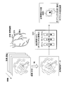
- FIG. 4 is an explanatory diagram showing an object position estimation processing method using the estimation learning model 341.
- the estimation learning model 341 is a model for outputting the position and range of an object such as a blood vessel wall portion and a guide wire included in a medical image, and the type of the object.
- the estimation learning model 341 is, for example, a convolutional neural network (CNN) that has been trained by deep learning.
- the estimation learning model 341 is, for example, an input layer 341a into which a medical image is input, an intermediate layer 341b for extracting a feature amount of an image, and an output layer 341c for outputting information indicating the position and type of an object included in the medical image. And have.
- the information is referred to as an object estimation result.
- the input layer 341a of the estimation learning model 341 has a plurality of neurons that receive the input of the pixel value of each pixel included in the medical image, and passes the input pixel value to the intermediate layer 341b.
- the intermediate layer 341b has a configuration in which a convolution layer that convolves the pixel values of each pixel input to the input layer 341a and a pooling layer that maps the pixel values convoluted by the convolution layer are alternately connected, and is a medical image.
- the feature amount of the image is extracted while compressing the pixel information of.
- the intermediate layer 341b passes the extracted features to the output layer 341c.
- the output layer 341c has one or a plurality of neurons that output an object estimation result indicating the position, range, type, and the like of the image region of the object included in the image.
- the estimation model is CNN, but the configuration of the model is not limited to CNN.
- the estimation model may be, for example, a trained model having a configuration such as a neural network other than CNN, an SVM (Support Vector Machine), a Bayesian network, or a regression tree.
- the estimation learning model 341 prepares training data in which a medical image including objects such as a blood vessel wall and a guide wire and a label indicating the position and type of each object are associated with each other, and untrained using the training data. It can be generated by machine learning the neural network of.
- the estimation learning model 341 configured in this way, by inputting the medical image into the estimation learning model 341 as shown in FIG. 4, information indicating the position and type of the object included in the medical image can be obtained. Can be done. Specifically, the estimation learning model 341 can recognize the annular region where the ultrasonic echo is small as a feature of the blood vessel wall portion, and can estimate the position and range of the blood vessel wall portion. Further, the estimation learning model 341 can estimate the position and range of the guide wire by using the region of the linear acoustic shadow and the portion where the ultrasonic echo at the tip thereof is large as a feature of the guide wire.
- Acoustic shading is a phenomenon in which when a hard object such as a guide wire is present in a blood vessel, a part of the image is blacked out because the reflected wave of ultrasonic waves does not reach the catheter 1.
- FIG. 4 for convenience of illustration, the region where the acoustic shadow is generated is shown by hatching.
- the object estimation result shown in FIG. 4 conceptually shows the information of the estimation result.
- control unit 31 that has completed the process of step S12 sets the areas of interest A1 and A2 according to the type and position of the object (step S13).
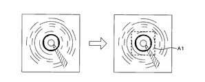
- FIGS. 5 and 6 are explanatory views showing an example of how to set the regions of interest A1 and A2.
- Areas of interest A1 and A2 are areas defined with reference to the position of the object estimated in the process of step S12, as shown in FIGS. 5 and 6.
- the control unit 31 sets the region including the entire estimated object as the region of interest A1 with the position of the object estimated by the estimation learning model 341 as the center. do.
- the region of interest A1 is, for example, a square, and the region of interest A1 is set by its apex position and its vertical and horizontal lengths.
- the area of interest A1 is a rectangular area including 10 pixels or more outside the object with reference to the center of the object.
- the size of the region of interest A1 may be a predetermined value.
- the control unit 31 When the object is a guide wire inserted into the blood vessel lumen, as shown in FIG. 6, the control unit 31 has a region of interest A2 whose top or end is the position of the object estimated by the estimation learning model 341. Set as. For example, the control unit 31 sets a rectangular area of interest A2 in which the position of the object is the apex and the line including the center of the catheter 1 and the position of the object is the diagonal line.
- control unit 31 can estimate the type of the object included in the medical image and its approximate position by the processing of steps S11 to S14, the other plurality of medical images are included in the areas of interest A1 and A2. All you have to do is detect a specific object.
- the control unit 31 extracts an image portion based on the position of the estimated object from the medical image according to the type of the estimated object (step S14).
- the control unit 31 standardizes the extracted medical image into an image portion of a predetermined size (step S15). For example, a medical image is converted into square image data of a predetermined size.
- the control unit 31 selects the recognition learning model to be used according to the type of the object included in the partial image (step S16). That is, when the partial image includes an object such as a blood vessel wall portion, the control unit 31 selects the first recognition learning model 342. When the partial image contains an object such as a guide wire, the control unit 31 selects the second recognition learning model 343. Then, the control unit 31 recognizes the object included in the image portion by inputting the extracted image portions of the interest regions A1 and A2 into the first recognition learning model 342 or the second recognition learning model 343 (step S17). ).
- FIG. 7 is an explanatory diagram showing an object recognition processing method.
- the first recognition learning model 342 is learned so that the region of the blood vessel wall portion in the image portion can be recognized on a pixel-by-pixel basis.
- the second recognition learning model 343 is learned so that the region of the guide wire in the image portion can be recognized on a pixel-by-pixel basis. Since the first cognitive learning model 342 and the second cognitive learning model 343 have the same configuration, the configuration of the first cognitive learning model 342 will be described.
- the first recognition learning model 342 is, for example, a convolutional neural network (CNN) that has been trained by deep learning.
- the first recognition learning model 342 recognizes an object on a pixel-by-pixel basis by an image recognition technique using so-called Semantic Segmentation.
- the first recognition learning model 342 outputs an input layer 342a into which an image portion is input, an intermediate layer 342b that extracts and restores an image feature amount, and a label image indicating an object included in the image portion in pixel units. It has a layer 342c and.
- the first recognition learning model 342 is, for example, U-Net.
- the input layer 342a of the estimation learning model 341 has a plurality of neurons that receive the input of the pixel value of each pixel included in the image portion, and passes the input pixel value to the intermediate layer 342b.
- the intermediate layer 342b has a convolutional layer (CONV layer) and a deconvolutional layer (DECONV layer).
- CONV layer convolutional layer
- DECONV layer deconvolutional layer
- the convolution layer is a layer that dimensionally compresses image data. Dimensional compression extracts the features of the object.
- the deconvolution layer undergoes a deconvolution process to restore it to its original dimension.
- the restoration process in the deconvolution layer produces a binarized label image indicating whether each pixel in the image is an object.
- the output layer 342c has one or more neurons that output a label image.
- the label image is, for example, an image in which the pixel corresponding to the blood vessel wall portion is the class “1” and the pixel corresponding to the
- the second recognition learning model 343 has the same configuration as the first recognition learning model 342, recognizes the guide wire included in the image portion on a pixel-by-pixel basis, and outputs the generated label image.
- the label image is, for example, an image in which the pixel corresponding to the guide wire is class "1" and the pixel corresponding to the other image is class "0".
- the first recognition learning model 342 prepares training data having a medical image including the blood vessel wall portion and a label image showing pixels of the blood vessel wall portion in the medical image, and uses the training data to create an unlearned neural network. It can be generated by machine learning.
- the second recognition learning model 343 can also be generated in the same manner.
- the image portion including the blood vessel wall portion is input to the first recognition learning model 342 to display the blood vessel wall portion in pixel units.
- the label image shown is obtained.
- the second recognition learning model 343 as shown in FIG. 7, when the image portion including the guide wire is input to the second recognition learning model 343, a label image showing the guide wire is obtained in pixel units. Be done.
- the learning model for recognizing the blood vessel wall and the learning model for recognizing the guide wire are separately configured, but one learning model is used to recognize the blood vessel wall and the guide wire. It may be configured as follows.
- the control unit 31 that has completed the process of step S17 changes the position of the object included in the image portion to the absolute coordinate position of the object in the original medical image based on the positions of the regions of interest A1 and A2 in the original medical image. Convert (step S18).
- control unit 31 accepts the selection of the type of object to be superimposed and displayed on the medical image by the input device 5 (step S19).
- the control unit 31 superimposes and displays the guide images G1 and G2 indicating the positions of the selected objects among the objects included in the medical image on the medical image (step S20).
- FIG. 8 is an explanatory diagram showing a display example of the guide images G1 and G2.
- the control unit 31 superimposes and displays the guide image G1 indicating the pixel position corresponding to the object on the blood vessel wall portion on the medical image.
- the control unit 31 superimposes and displays the guide image G2 indicating the pixel position corresponding to the object of the guide wire on the medical image.
- the control unit 31 uses the guide images G1 and G2 indicating the pixel positions corresponding to the objects of the blood vessel wall and the guide wire as medical images. Overlay display.
- the guide images G1 and G2 may be displayed in different modes depending on the type of object. For example, it is preferable to display guide images G1 and G2 having different line types and colors. Further, the original image in which the guide images G1 and G2 are not superimposed may be displayed side by side together with the image in which the guide images G1 and G2 are superimposed on the medical image. Further, the image on which the guide images G1 and G2 are superimposed and the original image on which the guide images G1 and G2 are not superimposed may be selectively switched and displayed.
- control unit 31 determines whether or not the inspection has been completed (step S21). If it is determined that the inspection has not been completed (step S21: NO), the control unit 31 returns the process to step S14. When it is determined that the inspection is completed (step S21: YES), the control unit 31 ends a series of processes.
- the image processing device 3 According to the computer program P, the image processing device 3, and the information processing method configured in this way, it is possible to analyze the medical image obtained by scanning the blood vessel and immediately recognize the object related to the diagnostic assistance. Then, for the purpose of assisting the diagnosis of the doctor, the guide images G1 and G2 showing the blood vessel wall portion, the guide wire, and the like can be superimposed and displayed on the medical image.
- the position of the object is approximately specified, and then the interest is obtained.
- the object By recognizing the object included in the image portion of the areas A1 and A2 on a pixel-by-pixel basis, the object can be recognized immediately.
- the image processing device 3, the computer program P, and the information processing method described in the first embodiment are examples, and are not limited to the configuration of the first embodiment.
- a blood vessel is exemplified as an observation or diagnosis target, but the present invention can also be applied when observing a luminal organ such as an intestine other than the blood vessel.
- the ultrasonic image was described as an example of the medical image, the medical image is not limited to the ultrasonic image.
- the medical image may be, for example, an OCT (Optical Coherence Tomography) image.
- OCT Optical Coherence Tomography
- the blood vessel wall and the guide wire are exemplified as the objects to be recognized, the positions of the objects such as the blood vessel lumen boundary, the medical instrument such as a stent, and the calcified part in the blood vessel are estimated and recognized, and each object is shown.
- a guide image may be displayed.
- the blood vessel wall is illustrated as an object when setting a rectangular area of interest A1 centered on the estimated position of the object, but the blood vessel lumen boundary, a stent, or the like is non-linear.
- the region of interest A1 may be set in the same manner.
- a guide wire is illustrated as an object when setting a rectangular area of interest A2 whose apex is the estimated position of the object.
- the area of interest A2 may be set in the same manner.
- the image recognition process is performed by setting the region of interest A2 including a linear object such as a guide wire
- the image is converted into a medical image centered on the circumferential direction ⁇ and the radial direction r of the blood vessel, and after conversion. It is advisable to extract the image portion of the region of interest A2 from the medical image of.
- FIG. 9 is an explanatory diagram showing a modified example of the extraction method of the image portion of the region of interest A2.
- the medical image shown in FIG. 9 is a medical image centered on the circumferential direction ⁇ and the radial direction r of the blood vessel.
- the thick line portion is the image portion corresponding to the region of interest A2.
- FIG. 10 is an explanatory diagram showing a configuration example of the diagnostic imaging system.
- the diagnostic imaging system according to the second embodiment is different in that the information processing device 6 which is a server executes the analysis process of the medical image. Therefore, the above differences will be mainly described below. Since other configurations and actions and effects are the same as those in the first embodiment, the corresponding parts are designated by the same reference numerals and detailed description thereof will be omitted.
- the diagnostic imaging system includes an information processing device 6 and a diagnostic imaging device 200.
- the information processing device 6 and the diagnostic imaging device 200 are communicated and connected via a network N such as a LAN (Local Area Network) or the Internet.
- the information processing device 6 and the diagnostic imaging device 200 are communicated and connected via a network N such as a LAN (Local Area Network) or the Internet.
- FIG. 11 is a block diagram showing a configuration example of the information processing device 6.
- the information processing device 6 is a computer and includes a control unit 61, a main storage unit 62, a communication unit 63, and an auxiliary storage unit 64.
- the communication unit 63 is a communication circuit for transmitting and receiving data to and from the image processing device 3 via the network N.
- the hardware configurations of the control unit 61, the main storage unit 62, the communication unit 63, and the auxiliary storage unit 64 are the same as those of the image processing device 3 described in the first embodiment.
- the computer program P, the estimation learning model 641, the first recognition learning model 642, the second recognition learning model 643, and the recording medium 6a stored in the auxiliary storage unit 64 are also the same as the various programs and models of the first embodiment.
- the information processing device 6 may be a multi-computer composed of a plurality of computers, or may be a virtual machine virtually constructed by software.
- the information processing device 6 may be a local server installed in the same facility (hospital or the like) as the diagnostic imaging device 200, or may be a cloud server communicatively connected to the diagnostic imaging device 200 via the Internet or the like.
- the information processing device 6 configured in this way acquires a medical image from the image processing device 3 via the network N, and executes the same processing as the image processing device 3 of the first embodiment based on the acquired medical image. Then, the recognition result of the object is transmitted to the image device.
- the image processing device 3 acquires the recognition result of the object transmitted from the information processing device 6, superimposes a guide image indicating the position of the object on the medical image, and displays it on the display device 4 as shown in FIG.
- the information processing device 6, the computer program P, and the information processing method according to the second embodiment can analyze the medical image obtained by scanning the blood vessel and immediately recognize the object related to the diagnostic assistance. can.
Landscapes
- Engineering & Computer Science (AREA)
- Health & Medical Sciences (AREA)
- Physics & Mathematics (AREA)
- Theoretical Computer Science (AREA)
- General Physics & Mathematics (AREA)
- Life Sciences & Earth Sciences (AREA)
- Computer Vision & Pattern Recognition (AREA)
- General Health & Medical Sciences (AREA)
- Multimedia (AREA)
- Medical Informatics (AREA)
- Radiology & Medical Imaging (AREA)
- Nuclear Medicine, Radiotherapy & Molecular Imaging (AREA)
- Veterinary Medicine (AREA)
- Animal Behavior & Ethology (AREA)
- Public Health (AREA)
- Surgery (AREA)
- Molecular Biology (AREA)
- Heart & Thoracic Surgery (AREA)
- Biomedical Technology (AREA)
- Biophysics (AREA)
- Pathology (AREA)
- Artificial Intelligence (AREA)
- Evolutionary Computation (AREA)
- Data Mining & Analysis (AREA)
- Vascular Medicine (AREA)
- Software Systems (AREA)
- Computing Systems (AREA)
- Databases & Information Systems (AREA)
- Quality & Reliability (AREA)
- Human Computer Interaction (AREA)
- Physiology (AREA)
- Bioinformatics & Cheminformatics (AREA)
- Bioinformatics & Computational Biology (AREA)
- Evolutionary Biology (AREA)
- General Engineering & Computer Science (AREA)
- Image Analysis (AREA)
- Ultra Sonic Daignosis Equipment (AREA)
Abstract
La présente invention amène un ordinateur à exécuter un processus d'acquisition d'une image médicale générée sur la base d'un signal détecté par un cathéter inséré dans un organe à lumière ; d'estimation de la position d'un objet inclus dans l'image médicale en entrant l'image médicale acquise dans un premier modèle d'apprentissage pour estimer la position de l'objet inclus dans au moins l'image médicale ; d'extraction depuis l'image médicale d'une partie d'image en utilisant la position estimée de l'objet en tant que référence ; et de reconnaissance de l'objet inclus dans la partie d'image en entrant la partie d'image extraite dans un second modèle d'apprentissage pour reconnaître l'objet inclus dans la partie d'image.
Priority Applications (2)
| Application Number | Priority Date | Filing Date | Title |
|---|---|---|---|
| JP2022511729A JP7561833B2 (ja) | 2020-03-30 | 2021-03-09 | コンピュータプログラム、情報処理方法及び情報処理装置 |
| US17/955,071 US12530793B2 (en) | 2020-03-30 | 2022-09-28 | Computer program, information processing method, and information processing device |
Applications Claiming Priority (2)
| Application Number | Priority Date | Filing Date | Title |
|---|---|---|---|
| JP2020-061512 | 2020-03-30 | ||
| JP2020061512 | 2020-03-30 |
Related Child Applications (1)
| Application Number | Title | Priority Date | Filing Date |
|---|---|---|---|
| US17/955,071 Continuation US12530793B2 (en) | 2020-03-30 | 2022-09-28 | Computer program, information processing method, and information processing device |
Publications (1)
| Publication Number | Publication Date |
|---|---|
| WO2021199961A1 true WO2021199961A1 (fr) | 2021-10-07 |
Family
ID=77929076
Family Applications (1)
| Application Number | Title | Priority Date | Filing Date |
|---|---|---|---|
| PCT/JP2021/009304 Ceased WO2021199961A1 (fr) | 2020-03-30 | 2021-03-09 | Programme informatique, procédé de traitement d'informations, et dispositif de traitement d'informations |
Country Status (3)
| Country | Link |
|---|---|
| US (1) | US12530793B2 (fr) |
| JP (1) | JP7561833B2 (fr) |
| WO (1) | WO2021199961A1 (fr) |
Cited By (1)
| Publication number | Priority date | Publication date | Assignee | Title |
|---|---|---|---|---|
| WO2025070351A1 (fr) * | 2023-09-25 | 2025-04-03 | テルモ株式会社 | Procédé de traitement d'informations, programme, dispositif de traitement d'informations, et procédé de génération de modèle |
Families Citing this family (2)
| Publication number | Priority date | Publication date | Assignee | Title |
|---|---|---|---|---|
| EP4538970A3 (fr) * | 2020-03-30 | 2025-08-27 | Terumo Kabushiki Kaisha | Programme informatique et dispositif de traitement d'informations |
| WO2022209657A1 (fr) * | 2021-03-30 | 2022-10-06 | テルモ株式会社 | Programme informatique, procédé de traitement d'informations et dispositif de traitement d'informations |
Citations (2)
| Publication number | Priority date | Publication date | Assignee | Title |
|---|---|---|---|---|
| JP2017503561A (ja) * | 2013-12-18 | 2017-02-02 | ハートフロー, インコーポレイテッド | 患者固有の解剖学的構造の画像データから冠動脈プラークの脆弱性を予測するシステム及び方法 |
| WO2020054543A1 (fr) * | 2018-09-11 | 2020-03-19 | 富士フイルム株式会社 | Dispositif et procédé de traitement d'image médicale, système d'endoscope, dispositif de processeur, dispositif d'aide au diagnostic et programme |
Family Cites Families (5)
| Publication number | Priority date | Publication date | Assignee | Title |
|---|---|---|---|---|
| EP2965263B1 (fr) | 2013-03-07 | 2022-07-20 | Bernhard Sturm | Segmentation multimodale dans des images intravasculaires |
| US10762637B2 (en) * | 2017-10-27 | 2020-09-01 | Siemens Healthcare Gmbh | Vascular segmentation using fully convolutional and recurrent neural networks |
| US11707242B2 (en) * | 2019-01-11 | 2023-07-25 | Pie Medical Imaging B.V. | Methods and systems for dynamic coronary roadmapping |
| US12020434B2 (en) * | 2019-04-02 | 2024-06-25 | Koninklijke Philips N.V. | Segmentation and view guidance in ultrasound imaging and associated devices, systems, and methods |
| US11710238B2 (en) * | 2019-10-24 | 2023-07-25 | Case Western Reserve University | Plaque segmentation in intravascular optical coherence tomography (OCT) images using deep learning |
-
2021
- 2021-03-09 JP JP2022511729A patent/JP7561833B2/ja active Active
- 2021-03-09 WO PCT/JP2021/009304 patent/WO2021199961A1/fr not_active Ceased
-
2022
- 2022-09-28 US US17/955,071 patent/US12530793B2/en active Active
Patent Citations (2)
| Publication number | Priority date | Publication date | Assignee | Title |
|---|---|---|---|---|
| JP2017503561A (ja) * | 2013-12-18 | 2017-02-02 | ハートフロー, インコーポレイテッド | 患者固有の解剖学的構造の画像データから冠動脈プラークの脆弱性を予測するシステム及び方法 |
| WO2020054543A1 (fr) * | 2018-09-11 | 2020-03-19 | 富士フイルム株式会社 | Dispositif et procédé de traitement d'image médicale, système d'endoscope, dispositif de processeur, dispositif d'aide au diagnostic et programme |
Cited By (1)
| Publication number | Priority date | Publication date | Assignee | Title |
|---|---|---|---|---|
| WO2025070351A1 (fr) * | 2023-09-25 | 2025-04-03 | テルモ株式会社 | Procédé de traitement d'informations, programme, dispositif de traitement d'informations, et procédé de génération de modèle |
Also Published As
| Publication number | Publication date |
|---|---|
| US20230017334A1 (en) | 2023-01-19 |
| US12530793B2 (en) | 2026-01-20 |
| JPWO2021199961A1 (fr) | 2021-10-07 |
| JP7561833B2 (ja) | 2024-10-04 |
Similar Documents
| Publication | Publication Date | Title |
|---|---|---|
| US12530793B2 (en) | Computer program, information processing method, and information processing device | |
| CN115334976B (zh) | 计算机程序、信息处理方法、信息处理装置以及模型生成方法 | |
| JP2022055170A (ja) | コンピュータプログラム、画像処理方法及び画像処理装置 | |
| US20240242351A1 (en) | Medical image processing apparatus, method, and medium | |
| WO2022071264A1 (fr) | Programme, procédé de génération de modèle, dispositif de traitement d'informations et procédé de traitement d'informations | |
| WO2022071265A1 (fr) | Programme, et dispositif et procédé de traitement d'informations | |
| JP2026012527A (ja) | コンピュータプログラム、情報処理方法及び情報処理装置 | |
| US20240013434A1 (en) | Program, information processing method, and information processing device | |
| US12518382B2 (en) | Medical system, method for processing medical image, and medical image processing apparatus | |
| JP7803928B2 (ja) | プログラム、画像処理方法及び画像処理装置 | |
| JP7686525B2 (ja) | コンピュータプログラム、情報処理方法、及び情報処理装置 | |
| JP2025100867A (ja) | コンピュータプログラム、情報処理方法、及び情報処理装置 | |
| US12283048B2 (en) | Diagnosis support device, diagnosis support system, and diagnosis support method | |
| US20250248664A1 (en) | Image diagnostic system and method | |
| JP7686523B2 (ja) | コンピュータプログラム、情報処理方法、及び情報処理装置 | |
| US20250221625A1 (en) | Image diagnostic system, image diagnostic method, and storage medium | |
| JP7813276B2 (ja) | コンピュータプログラム、情報処理方法及び情報処理装置 | |
| JP7680325B2 (ja) | コンピュータプログラム、情報処理装置及び情報処理方法 | |
| US20250221624A1 (en) | Image diagnostic system, image diagnostic method, and storage medium | |
| CN112990267B (zh) | 基于风格迁移模型的乳腺超声成像方法、装置及存储介质 | |
| JP2024050056A (ja) | コンピュータプログラム、学習モデル、情報処理方法、及び情報処理装置 | |
| JP2024139509A (ja) | プログラム、画像処理方法、画像処理装置及びモデル生成方法 | |
| JP2024142137A (ja) | プログラム、画像処理方法及び画像処理装置 | |
| JP2025052747A (ja) | 情報処理方法、プログラム及び情報処理装置 | |
| JP2023049952A (ja) | コンピュータプログラム、情報処理装置、情報処理方法及び学習モデル生成方法 |
Legal Events
| Date | Code | Title | Description |
|---|---|---|---|
| 121 | Ep: the epo has been informed by wipo that ep was designated in this application |
Ref document number: 21778775 Country of ref document: EP Kind code of ref document: A1 |
|
| ENP | Entry into the national phase |
Ref document number: 2022511729 Country of ref document: JP Kind code of ref document: A |
|
| NENP | Non-entry into the national phase |
Ref country code: DE |
|
| 122 | Ep: pct application non-entry in european phase |
Ref document number: 21778775 Country of ref document: EP Kind code of ref document: A1 |