WO2021200065A1 - 接合ストランド、及びその製造方法 - Google Patents
接合ストランド、及びその製造方法 Download PDFInfo
- Publication number
- WO2021200065A1 WO2021200065A1 PCT/JP2021/010318 JP2021010318W WO2021200065A1 WO 2021200065 A1 WO2021200065 A1 WO 2021200065A1 JP 2021010318 W JP2021010318 W JP 2021010318W WO 2021200065 A1 WO2021200065 A1 WO 2021200065A1
- Authority
- WO
- WIPO (PCT)
- Prior art keywords
- strand
- joint
- strands
- fibers
- joining
- Prior art date
- Legal status (The legal status is an assumption and is not a legal conclusion. Google has not performed a legal analysis and makes no representation as to the accuracy of the status listed.)
- Ceased
Links
Images


Classifications
-
- B—PERFORMING OPERATIONS; TRANSPORTING
- B65—CONVEYING; PACKING; STORING; HANDLING THIN OR FILAMENTARY MATERIAL
- B65H—HANDLING THIN OR FILAMENTARY MATERIAL, e.g. SHEETS, WEBS, CABLES
- B65H69/00—Methods of, or devices for, interconnecting successive lengths of material; Knot-tying devices ;Control of the correct working of the interconnecting device
- B65H69/06—Methods of, or devices for, interconnecting successive lengths of material; Knot-tying devices ;Control of the correct working of the interconnecting device by splicing
-
- D—TEXTILES; PAPER
- D02—YARNS; MECHANICAL FINISHING OF YARNS OR ROPES; WARPING OR BEAMING
- D02J—FINISHING OR DRESSING OF FILAMENTS, YARNS, THREADS, CORDS, ROPES OR THE LIKE
- D02J1/00—Modifying the structure or properties resulting from a particular structure; Modifying, retaining, or restoring the physical form or cross-sectional shape, e.g. by use of dies or squeeze rollers
- D02J1/18—Separating or spreading
-
- B—PERFORMING OPERATIONS; TRANSPORTING
- B65—CONVEYING; PACKING; STORING; HANDLING THIN OR FILAMENTARY MATERIAL
- B65H—HANDLING THIN OR FILAMENTARY MATERIAL, e.g. SHEETS, WEBS, CABLES
- B65H2701/00—Handled material; Storage means
- B65H2701/30—Handled filamentary material
- B65H2701/31—Textiles threads or artificial strands of filaments
- B65H2701/312—Fibreglass strands
-
- B—PERFORMING OPERATIONS; TRANSPORTING
- B65—CONVEYING; PACKING; STORING; HANDLING THIN OR FILAMENTARY MATERIAL
- B65H—HANDLING THIN OR FILAMENTARY MATERIAL, e.g. SHEETS, WEBS, CABLES
- B65H2701/00—Handled material; Storage means
- B65H2701/30—Handled filamentary material
- B65H2701/31—Textiles threads or artificial strands of filaments
- B65H2701/314—Carbon fibres
-
- B—PERFORMING OPERATIONS; TRANSPORTING
- B65—CONVEYING; PACKING; STORING; HANDLING THIN OR FILAMENTARY MATERIAL
- B65H—HANDLING THIN OR FILAMENTARY MATERIAL, e.g. SHEETS, WEBS, CABLES
- B65H2701/00—Handled material; Storage means
- B65H2701/30—Handled filamentary material
- B65H2701/38—Thread sheet, e.g. sheet of parallel yarns or wires
Definitions
- the present invention relates to a bonded strand obtained by joining strands composed of a plurality of monofilaments bundled together and a method for producing the same.
- strands carbon fiber strands and glass fiber strands
- SMC sheet molding compound
- the strength of the knot varies depending on the skill level of the operator, the strands may be cut, and the knot may not be cut in the cutting process. Long chopped strands can get mixed into the product. Further, even when the knot has passed through the cutting process, the knot may remain in the SMC or the stampable sheet, which may cause a defect when heat / pressure molding is performed.
- the joint becomes stronger by twisting. Therefore, it may not be cut in the cutting step, and the chopped strands after the cutting step may be sprayed as one chopped strand mass in a twisted state, which may cause uneven basis weight.
- Patent Document 1 discloses a method of joining a plurality of flat strands while maintaining the flat shape.
- Patent Document 2 shows that by implementing air splices at a plurality of locations in the fiber direction, the strand bonding strength is ensured even when the splice strength of each is weak.
- Patent Document 3 by dividing the strands into a plurality of strands and then twisting them together, it is difficult to form chopped strands having a large number of monofilaments on the chopped strands after cutting, and uneven basis weight is improved.
- the joint portion becomes rigid in order to maintain and handle the flat strand shape. Therefore, when the strands are cut into chopped strands, there is a problem in cutability, and even if the joint can be cut, the number of monofilaments constituting the chopped strands increases as compared with the chopped strands in other portions. In addition, the characteristics of the strands that have undergone partial defibration treatment with the aim of reducing the bundle width of the chopped strands may not be fully exhibited.
- Patent Document 2 it is possible to reduce the splice strength of each one, reduce the entanglement of monofilaments, and improve the cuttability while ensuring the strand joint strength of the joint portion as a whole.
- a joint is a chopped strand
- the number of monofilaments constituting the chopped strand increases.
- the characteristics of the flat strands that have been pre-spread to reduce the bundle thickness of the chopped strands and the characteristics of the strands that have been partially split to reduce the bundle width of the chopped strands are not fully exhibited. There is a risk.
- Patent Document 3 by twisting the strands, the joint portion becomes rigid and the cutability deteriorates, and when the twisted portion is wound tightly, the wall thickness becomes thick and the characteristics such as flat strands are easily lost. Further, since the entire overlapping portion of the strand ends is twisted and joined, the region affected by the twisting is large, and many chopped strands may be affected by the twisting when the chopped strand is used.
- the present invention exhibits good cutability in the case of chopped strands and good dispersibility after cutting by optimizing the bonding state of the strands, and the bundle width of the chopped strands. It is an object of the present invention to provide a bonded strand capable of controlling the above, and a method for producing the same.
- the present invention mainly employs any of the following means in order to solve such a problem.
- the overlapped portion includes a first strand end portion in which fibers are oriented in one direction and a second strand end portion in which fibers are oriented in one direction.
- a joint strand having a joint portion in which the fibers of the first strand and the fibers of the second strand are entangled with each other.
- the joint portion has slits extending in the fiber orientation direction at one location or a plurality of locations arranged in a direction orthogonal to the fiber orientation direction, and has a joint portion adjacent to the slit.
- a joining strand in which the monofilaments of the first strand and the second strand are entangled.
- a superposition portion is provided by superimposing a first strand end portion in which fibers are oriented in one direction and a second strand end portion in which fibers are oriented in one direction, and the superposition portion is divided.
- slits extending in the fiber orientation direction are provided at one place or at a plurality of places arranged in the direction orthogonal to the fiber orientation direction, and a joint portion adjacent to the slit is formed, and then at the joint portion.
- a superimposing portion is provided by superimposing a first strand end portion in which fibers are oriented in one direction and a second strand end portion in which fibers are oriented in one direction.
- a joint is formed by entwining the monofilaments of the first strand and the second strand, and by piercing the joint with a dividing means, one place or a plurality of places arranged in a direction orthogonal to the orientation direction of the fibers can be formed.
- a method for producing a bonding strand which comprises providing a slit extending in the fiber orientation direction and forming a bonding portion adjacent to the slit.
- a bonded strand showing good cutability can be obtained. Further, when the joint portion of the obtained joint strand is cut to obtain a chopped strand, unevenness in the number of monofilaments constituting the chopped strand and unevenness in the bundle width of the chopped strand can be reduced. Therefore, in a chopped strand mat or the like produced by using it, unevenness of basis weight can be improved and mechanical properties can be improved.
- the present invention has a superposed portion in which a first strand end portion in which fibers are oriented in one direction and a second strand end portion in which fibers are oriented in one direction are superposed. It is a joint strand having a joint portion in which the fibers of the first strand and the fibers of the second strand are entangled in the above.
- the joint portion has slits extending in the fiber orientation direction at one location or a plurality of locations aligned in the direction orthogonal to the fiber orientation direction, and has a junction portion adjacent to the slit. At the junction portion, a monofilament is formed. By entanglement, the fibers of the first strand and the second strand are entangled.
- joint portion and “joint portion” are used separately, and a portion in which a “joint portion” in which monofilaments are entangled and one or a plurality of slits adjacent thereto are combined. Is referred to as the "joint”.
- the strand used in the present invention is composed of a large number of monofilaments arranged in one direction converged, and is organic such as aramid fiber, polyethylene fiber, and polyparaphenylene benzoxador (PBO) fiber.
- organic fibers such as fibers, glass fibers, carbon fibers, silicon carbide fibers, alumina fibers, tyranno fibers, genbuiwa fibers, ceramics fibers, metal fibers such as stainless steel fibers and steel fibers, and other boron fibers, natural fibers, and modified natural fibers. Examples thereof include strands using the above as a monofilament.
- carbon fibers are the lightest of these reinforcing fibers, have particularly excellent properties in terms of specific strength and specific elastic modulus, and are also excellent in heat resistance and chemical resistance. Therefore, it is suitable as a fiber-reinforced composite material.
- joining means a state in which the monofilaments constituting the first strand and the second strand are entangled (entangled), and the fibers are entangled to the extent that they are not easily dissociated by frictional force.
- a method of joining for example, there is a method of entwining and joining monofilaments by blowing air or repeatedly piercing a piercing means. Compared with the case where a knot is formed and joined by entanglement joining, a cutting defect is less likely to occur in the case of forming a chopped strand.
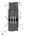
- FIG. 1 shows a top view of the joining strand according to the present invention.
- a joining portion 105 including a portion where the fibers are entangled.
- slits 103 and joint portions 104 are alternately arranged in a direction orthogonal to the fiber orientation direction.
- the monofilaments constituting the first strand 101 and the monofilaments constituting the second strand 102 are entangled with each other.
- the monofilament is not oriented in substantially one direction, so that the slit cannot be formed.
- the slit 103 is a crevice that penetrates the stacked first strand 101 and the second strand 102 in the stacking direction, and has a constant length in the fiber orientation direction. Therefore, the slit 103 divides the overlapping portion 106 of the first strand 101 and the second strand 102 in the direction orthogonal to the fiber orientation direction.
- One slit 103 may be provided at one joint portion, and when a plurality of slits 103 are provided, a plurality of slits 103 may be provided side by side in a direction orthogonal to the fiber orientation direction.
- the flexibility of the joint portion 105 is increased and the cuttability is improved. Further, the bundle width of the chopped strands obtained by cutting the joint portion 105 can be reduced, and the number of monofilaments constituting the chopped strands can be reduced. Further, the presence of the slit suppresses the entanglement of the monofilaments in the entangled portion and reduces the strand thickness, so that the bundle thickness of the chopped fiber bundle can be suppressed. As a result, the chopped strands are uniformly dispersed, so that the unevenness of the basis weight of the chopped strand mat or the like can be improved, and the mechanical properties can be improved.
- the spacing between the slits 103 is not particularly limited, but in order to obtain chopped strands with high homogeneity, it is preferable that the slits 103 are evenly spaced in the direction orthogonal to the fiber orientation direction.
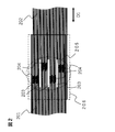
- the joining portions 104 and 204 in which the monofilaments are entangled may be provided in a state of being arranged in a state orthogonal to the fiber orientation direction D1 as shown in FIG. 1, and slightly fibers as shown in FIG. It may be provided in a state of being shifted in the orientation direction D1.
- the joint portion 104 is provided in a state of being arranged in a direction orthogonal to the fiber orientation direction D1
- the joint portion can be efficiently produced
- the joint portion 204 is provided in a state of being slightly shifted in the fiber orientation direction D1.
- the flexibility of the joint is increased and the cuttability is further improved.
- one overlapping portion is provided with 1 to 10 joint portions in the fiber orientation direction.
- the time required for joining can be shortened.
- the strand may be cut as a result of an excessive tension acting on the joint portion 104.
- FIG. 5D by providing the joint portions 505 at a plurality of locations in the fiber orientation direction D1, the tension acting on each of the joint portions can be dispersed, and the strands can be dispersed. Can be continuously supplied without cutting.
- the number of joints is preferably 1 or more and 10 or less in the fiber orientation direction with respect to one overlapping portion, and more preferably 2 or more and 5 or less.
- the spacing between the plurality of joints existing in the fiber orientation direction is not particularly limited, but when the joint strands are cut into chopped strands in the next step, it is preferably longer than the cut length of the chopped strands, and each joint is formed. Handleability is better when the intervals between the parts are equal.
- one joint portion is provided with 1 to 30 slits for dividing the joint portion into a plurality of portions.
- the number of slits may be one for one joint, but by providing a plurality of slits in the direction orthogonal to the fiber orientation direction, the flexibility of the joint is improved and the cuttability is further improved. Further, the bundle width of the chopped strands after cutting is reduced, and the number of monofilaments constituting the chopped strands is reduced, so that the chopped strands can be more uniformly dispersed. Therefore, it is possible to improve the unevenness of the basis weight of the chopped strand mat and the like, and improve the mechanical properties.
- the length of the joint portion in the fiber orientation direction is 0.2 mm or more and less than 20 mm.
- the length of the joint portion in the fiber orientation direction is preferably 0.2 mm or more and less than 20 mm, and more preferably 0.2 mm or more and less than 10 mm.
- the length of the overlapped portion in the fiber orientation direction is preferably 10 to 500 mm. If the overlapped portion is long, the amount of strands supplied to the manufacturing apparatus increases, and if a part of the overlapped portion is longer than the overlapped portion of the other portion, the chopped strand mat becomes uneven. In addition, it leads to deterioration of material yield. On the other hand, if the overlapped portion is short, it is not possible to provide a joint portion having a sufficient length in the overlapped portion, and the joining strength may decrease. Therefore, the length of the overlapped portion in the fiber orientation direction is preferably 10 to 500 mm.
- the length of the slit is preferably 10 to 200 mm. If the length of the slit is short, the length of the joint portion in the fiber orientation direction is also shortened as a result, and there is a risk that sufficient joint strength cannot be obtained. On the other hand, if the length of the slit is long, the monofilament may break more often. Further, if the length of the overlapped portion in the fiber orientation direction becomes longer, the amount of strands supplied to the manufacturing apparatus increases, and if a part of the overlapped portion is longer than the overlapped portion of the other portion, the chopped portion is chopped. In addition to causing unevenness in the appearance of the strand mat, it also leads to deterioration of the material yield.
- the length of the slit is 10 to 200 mm, which is shorter than the length in the fiber orientation direction of the overlapped portion and longer than the length in the fiber orientation direction of the joint portion.
- the strand is made of carbon fiber. Is preferable. Since carbon fibers have thin monofilaments, when they are joined by confounding, the monofilaments are well entangled and the joint becomes strong.
- the carbon fiber strand is not particularly limited, but it is preferable to use a carbon fiber strand in which the number of monofilaments constituting the strand is 12,000 or more and 60,000 or less. If the number of monofilaments is within this range, even if the slits described above are provided, the number of monofilaments required to form each joint portion can be secured, and breakage of the joint portion can be prevented.
- the present invention can be particularly preferably applied to the case where the strand is a strand which has been subjected to a partial defibration treatment.
- the partial defibration treatment is a treatment for intermittently performing the defibration treatment along the orientation direction of the monofilaments constituting the strand (that is, a treatment for intermittently repeatedly slitting the strand).
- the first strand end portion in which the fibers are oriented in one direction and the second strand end portion in which the fibers are oriented in one direction are overlapped to provide an overlapping portion, and the overlapping portion is provided.
- the fibers of the first strand and the fibers of the second strand are entangled to form a joint portion, and by piercing the joint portion with a dividing means, one place or a plurality of places arranged in a direction orthogonal to the orientation direction of the fibers can be formed.
- a method for producing a bonded strand which comprises providing a slit extending in the fiber orientation direction and forming a bonded portion adjacent to the slit.
- the means for entwining and joining the fibers of the first strand and the second strand is not particularly limited, but any means for entwining the monofilaments of the first strand and the second strand by ejecting a gas.
- any means for entwining the monofilaments of the first strand and the second strand by ejecting a gas For example, it is preferable because the bonding can be performed while reducing the breakage of the fibers.
- the strength of the joint portion of the strand may be set within a range in which the next step can be passed, and if the joint is excessively strengthened, the cuttability is deteriorated.
- the strength of the strand joint is preferably 1N or more and 500N or less, and 5N or more and 250N. The following is more preferable.
- the length of the joint portion in the fiber orientation direction is equal to or less than the length of the overlapped portion and is 1 to 90% of the length of the overlap portion in the fiber orientation direction, sufficient joint strength can be obtained and the joint portion is strong.
- the slit can be easily provided, and it is possible to avoid providing a joint portion not including the slit, which is connected in the direction orthogonal to the fiber orientation direction.
- the length of the joint can be controlled by controlling the length of the gas outlet in the fiber orientation direction.
- the direction orthogonal to the fiber and the thickness direction of the plate should be the same direction.
- a plurality of plates may be arranged and pierced at arbitrary intervals in the fiber orthogonal direction to divide the strands.
- FIG. 3 shows an example of the shape of the dividing means to be pierced when the slit is provided.
- the thickness of the dividing means in the orthogonal direction of the fibers is not particularly limited, but it is preferably as thin as long as the rigidity of the dividing means is maintained, and is preferably 0.1 to 2.0 mm.
- a blade may be formed on the edge of the dividing means, it may be left in a punched state, or it may be chamfered. Further, the material is not limited, and may be made of metal or plastic, for example.
- a blade such as a Thomson blade or a round blade may be pierced to divide the strand, and at that time, for example, a jig in which a plurality of blades are arranged at arbitrary intervals in the fiber orthogonal direction may be pierced to divide the strand. May be divided.
- the length of the dividing means in the fiber orientation direction is longer than the length of the joint portion where the fibers are entangled.
- the joints may be produced repeatedly (in order), or a means for producing a plurality of joints at once may be used.
- FIG. 4 shows a conceptual diagram in which the dividing means is pierced to provide a slit.
- the dividing means 401 is pierced in the strand thickness direction so as to be along the fiber orientation direction D1 of the strand and divided in the fiber orthogonal direction, the breakage of the monofilament can be suppressed and the slit can be provided.
- the strands may be widened before joining the strands, and by performing the widening treatment, the area where the dividing means can be pierced after the strands are joined becomes wider, and the strands are divided into desired division ratios with high accuracy. Will be possible.
- slits can be provided in the strands with high accuracy.
- the bonded strand can be produced by the following methods in addition to the above methods. That is, a first strand end portion in which the fibers are oriented in one direction and a second strand end portion in which the fibers are oriented in one direction are overlapped to provide an overlapping portion, and the overlapping portion is used as a dividing means.
- slits extending in the fiber orientation direction are provided at one location or at a plurality of locations aligned in the direction orthogonal to the fiber orientation direction, and a joint portion adjacent to the slit is formed, and then the first joint portion at the joint portion is formed.
- the fibers of the strand and the second strand are entangled to form a joint portion consisting of a slit and a joint portion.
- the means for entwining and joining the fibers of the first strand and the second strand is not particularly limited, but any means for entwining the monofilaments of the first strand and the second strand by ejecting a gas. , It is preferable because it can be joined while reducing the breakage of fibers. At this time, the strength of the joint portion of the strand may be set within a range in which the next step can be passed, and if the joint portion is excessively strengthened, the cuttability is deteriorated.
- the strength of the strand joint portion is preferably 1N or more and 500N or less, and 5N or more and 250N or less. It is even more preferable to have it.
- the length of the joint portion in the fiber orientation direction is equal to or less than the length of the slit and is 1 to 90% of the length of the slit in the fiber orientation direction, sufficient joint strength can be obtained and in the fiber orientation direction. It is possible to avoid providing a joint portion that is connected in the orthogonal direction and does not include a slit. At this time, for example, the length of the joint can be controlled by controlling the length of the gas outlet in the fiber orientation direction.
- the fibers of the first strand and the fibers of the second strand By superimposing the fibers of the first strand and the fibers of the second strand, providing slits, and then joining the joint sites by entanglement, it is possible to reduce the breakage of the monofilament.
- a method of providing a slit there is a method of piercing a strand with a plate.
- the direction orthogonal to the fiber and the thickness direction of the plate should be the same direction.
- a plurality of plates may be arranged and pierced at arbitrary intervals in the direction orthogonal to the fiber to divide the strands.
- FIG. 3 shows an example of the shape of the dividing means to be pierced when the slit is provided.
- the thickness of the dividing means in the orthogonal direction of the fibers is not particularly limited, but it is preferably as thin as long as the rigidity of the dividing means is maintained, and is preferably 0.1 to 2.0 mm.
- a blade may be formed on the edge of the dividing means, the blade may be left out, or a chamfering process may be performed. Further, the material is not limited and may be made of metal or plastic, for example.
- a blade such as a Thomson blade or a round blade may be pierced to divide the strand, and at that time, for example, a jig in which a plurality of blades are arranged at arbitrary intervals in the fiber orthogonal direction may be pierced to divide the strand. May be divided.
- the length of the dividing means in the fiber orientation direction is longer than the length of the joint portion where the fibers are entangled.
- the joints may be repeatedly produced, or a means for producing a plurality of joints at once may be used.
- FIG. 4 shows a conceptual diagram in which the dividing means is pierced to provide a slit.
- the dividing means 401 is pierced in the strand thickness direction so as to be along the fiber orientation direction D1 of the strand and divided in the fiber orthogonal direction, the breakage of the monofilament can be suppressed and the slit can be provided.
- the strands may be widened before joining the strands, and by performing the widening treatment, the area where the dividing means can be pierced after the strands are joined becomes wider, and the strands are divided into desired division ratios with high accuracy. Will be possible.
- At least one of the first strand and the second strand is a partially defibrated strand.
- Example 1 As the strand, a continuous carbon fiber strand having 50,000 filaments (manufactured by ZOLTEK, product name: "ZOLTEK (registered trademark)" PX35-50K) was used.
- Two strands were prepared, and the ends of the two strands were overlapped in the fiber orientation direction to provide a 50 mm superposition portion.
- Five slits with a length of 45 mm are provided by piercing the overlapped portion with a stainless flat plate having a plate thickness of 0.2 mm and a length of 100 mm so that the length direction of the flat plate and the fiber orientation direction of the strands are the same.
- an air splicer (MESDAN air splicer (product name: JOINTAIR (registered trademark), model: 116)) is used to form a joint site in which monofilaments are entangled in the overlapped portion partitioned by slits, and then joined. Obtained a strand.
- the length of the joint portion in the fiber orientation direction was 8 mm.
- the SMC manufacturing apparatus has a strand cutting machine 1300 mm above the first carrier sheet that is horizontally conveyed, and the chopped strands that have been cut are hit by a distributor that exists 700 mm below the strand cutting machine. It is a device to be sprayed.
- the distributor consists of a rotating shaft and wires arranged around the rotating shaft, and 12 wires are attached at equal intervals so as to form a circle when viewed in the axial direction, and the rotating shaft is attached to the transport direction of the first carrier sheet.
- the wire is mounted so as to be orthogonal and horizontal, and the wire has a speed of 4 m / sec so that the chopped strand that has been cut and dropped collides with the wire and is blown forward and scattered by free fall. Rotate the distributor so that it becomes.
- a polypropylene first carrier sheet is pulled out from the first raw fabric roll and supplied to the first conveyor, and the matrix resin [A] paste is spread on the first carrier sheet with a doctor blade to a predetermined thickness. It was applied to form a first resin sheet.
- the joined strand was made into a chopped strand using a strand cutting machine of the SMC manufacturing apparatus, and was cut so that the chopped strand length was 25.4 mm.
- the chopped strands were dropped onto the first resin sheet and sprayed to continuously form sheet-shaped chopped strands in which the chopped strands were randomly oriented.
- a polypropylene second carrier sheet is pulled out from the second raw fabric roll and supplied to the second conveyor, and the matrix resin [A] paste is spread on the second carrier sheet with a doctor blade to a predetermined thickness. It was coated to form a second resin sheet.
- the second resin sheet was laminated on the sheet-shaped chopped strand, and pressure was applied from both sides to impregnate the sheet-shaped chopped strand with the matrix resin [A] to prepare SMC.
- the basis weight of the obtained SMC was 2000 g / m 2 , and the fiber weight content was 57%.
- the SMC is cut out to 265 ⁇ 265 mm so that the transport direction (MD direction) of the SMC in the SMC manufacturing apparatus is aligned 3
- the temperature is about 140 ° C. ⁇ under a pressure of 10 MPa by a heating type press molding machine. It was cured under the condition of 5 minutes to obtain a flat molded product having a size of 300 mm ⁇ 300 mm ⁇ 3 mm. The molded product showed a good appearance, and it was visually confirmed that there were no defects due to the mixing of the strand joints.
- VE Vinyl ester resin
- tert-butyl peroxybenzoate manufactured by Nippon Oil & Fats Co., Ltd., “perbutyl Z” (registered trademark)
- zinc stearate manufactured by Sakai Chemical Industry Co., Ltd., SZ-2000
- magnesium oxide manufactured by
- Example 2 As a strand, a continuous carbon strand having 50,000 filaments (manufactured by ZOLTEK, product name: "ZOLTEK (registered trademark)" PX35-50K) was prepared and widened in advance.
- a defibration treatment means was prepared in which iron plates for defibration processing having a protruding shape having a thickness of 0.3 mm, a width of 3 mm, and a height of 20 mm were set in parallel at equal intervals of 5 mm with respect to the width direction of the strands, and the width was widened. Partial fiber bundles (strands) were prepared by intermittently inserting and removing the strands as shown in FIG.
- FIG. 5 (a) is a schematic view of an air blowing device 500 having an air ejection portion 501, and (b) shows a state in which the ends of two strands are overlapped on the air blowing device 500.
- FIG. 5 (a) is a schematic view of an air blowing device 500 having an air ejection portion 501, and (b) shows a state in which the ends of two strands are overlapped on the air blowing device 500.
- FIG. 6C is a diagram showing a state in which air is ejected in a state where the strand dividing blade 504 (dividing means) is pierced into the overlapping portion
- FIG. 3D is a schematic view of the obtained bonded strand.
- the length of each air ejection portion 501 shown in FIG. 5A in the fiber orientation direction was 5 mm, and the length of the joint portion 507 in the fiber orientation direction was 7 mm.
- the bonded portion was chopped strands divided into 6 parts, showing good cutability and dispersibility. It was confirmed visually.
- the number of filaments of the chopped strand was about 10,000 to 20,000. Even in the state where the chopped strands were sprayed, that is, in the form of the chopped strand mat, the basis weight due to the inclusion of the large chopped strands did not occur. Further, it was confirmed that the bundle width of the chopped strand was also the division width of the strand joint, and the bundle width could be controlled.
- Example 2 an SMC was prepared in the same manner as in Example 1 to obtain an SMC having a fiber weight content of 57% at a basis weight of 2000 g / m 2. After curing the produced SMC at a temperature of 25 ⁇ 5 ° C. for one week after production, a flat molded product was produced in the same manner as in Example 1. The molded product showed a good appearance, and the strand joint was formed. It was visually confirmed that there were no defects due to mixing.
- Example 3 In order to provide five joints in the fiber orientation direction in the overlapped portion, the air ejection portion is set to five, and the length of the air ejection portion in the fiber orientation direction is set to 4 mm, and the length of the joint portion in the fiber orientation direction is set.
- a bonded strand was produced in the same manner as in Example 2 except that the size was set to 5 mm.
- the bonded portion was chopped strands divided into 6 parts, showing good cutability and dispersibility. This was visually confirmed, and the number of filaments of the chopped strand was about 10,000 to 20,000. Even in the state where the chopped strands were sprayed, that is, in the form of the chopped strand mat, the basis weight due to the inclusion of the large chopped strands did not occur. Further, it was confirmed that the bundle width of the chopped strand was also the division width of the strand joint, and the bundle width could be controlled.
- Example 2 an SMC was prepared in the same manner as in Example 1 to obtain an SMC having a fiber weight content of 57% at a basis weight of 2000 g / m 2. After curing the produced SMC at a temperature of 25 ⁇ 5 ° C. for one week after production, a flat molded product was produced in the same manner as in Example 1. The molded product showed a good appearance, and the strand joint was formed. It was visually confirmed that there were no defects due to mixing.
- the number of monofilaments at the joint was 99000 to 101000, and the number of monofilaments was high. It was a large chopped strand with a large number of monofilaments, compared to the non-joint portion with 49000 to 51,000. Also, when the cutter tries to cut the joint, the strands are not cut and the chopped strand length becomes longer than 25.4 mm and becomes 50.8 mm, or when it is cut in a partially connected state. It was confirmed that there was a problem, the cut property was poor, and the dispersibility was also poor.
- the basis weight was locally deteriorated due to the inclusion of the large chopped strands. Furthermore, it was confirmed that the bundle width of the chopped strand was the bundle width of the strand.
- an SMC was prepared in the same manner as in Example 1 to obtain an SMC having a fiber weight content of 57% at a basis weight of 2000 g / m 2.
- a flat molded product was produced in the same manner as in Example 1, and a large chopped strand derived from the joint was confirmed on the surface of the molded product. As a result, the molded product swelled due to the mixing of the strand joints.
- a continuous carbon strand having 50,000 filaments (manufactured by ZOLTEK, product name: "ZOLTEK (registered trademark)" PX35-50K) was prepared and widened in advance.
- a defibration treatment means was prepared in which iron plates for defibration processing having a protruding shape having a thickness of 0.3 mm, a width of 3 mm, and a height of 20 mm were set in parallel at equal intervals of 5 mm with respect to the width direction of the strands, and the width was widened.
- Partial fiber bundles (strands) were prepared by intermittently inserting and removing the strands as shown in FIG.
- the number of monofilaments at the joint was 99000 to 101000, and the number of monofilaments was It was a large chopped strand with a large number of monofilaments, compared to the non-joint portion with 2000 to 4000 strands.
- the cutter tries to cut the joint the strands are not cut and the chopped strand length becomes longer than 25.4 mm and becomes 50.8 mm, or when it is cut in a partially connected state. It was confirmed that there was a problem, the cut property was poor, and the dispersibility was also poor.
- the basis weight was locally deteriorated due to the inclusion of the large chopped strands.
- the bundle width of the chopped strands not including the joint portion was 5 mm, which was the defibration treatment width, whereas the bundle width of the chopped strands including the joint portion was the bundle width of the strands.
- an SMC was prepared in the same manner as in Example 1 to obtain an SMC having a fiber weight content of 57% at a basis weight of 2000 g / m 2.
- a flat molded product was produced in the same manner as in Example 1, and a large chopped strand derived from the joint was confirmed on the surface of the molded product. As a result, the molded product swelled due to the mixing of the strand joints.
- each strand is aligned, and the strand bundle ends are divided into five groups (A1, A2, ... A5) and (B1, B2, ... B5), respectively, and (A1 and B1).
- (A2 and B2), ... (A5 and B5) are aligned to provide a 30 mm overlapping portion
- each aligned portion is inserted into a tubular passage, and 0.6 MPa of compressed air is ejected into the passage. Twisted together. At this time, compressed air was ejected without fixing the strand ends so that the strand ends could freely rotate and twist in the passage.
- the length of the twisted portion in the fiber orientation direction was 30 mm.
- the twisted portion is wound tight and thickened by being twisted, and is thicker than the thickness of two strands stacked on top of each other, which is thicker than that of Examples 1 and 2. .. Furthermore, no monofilament entanglement between the strands was observed at the twisted portion.
- the number of monofilaments at the joint was 99000 to 101000, and the number of monofilaments was It was a large chopped strand with a large number of monofilaments, compared to the non-joint portion with 49000 to 51,000.
- the cutter tries to cut the joint the strands are not cut and the chopped strand length becomes longer than 25.4 mm and becomes 50.8 mm, or when it is cut in a partially connected state. It was confirmed that there was a problem, the cut property was poor, and the dispersibility was also poor. Further, in the state where the chopped strands were sprayed, that is, in the form of the chopped strand mat, the basis weight was locally deteriorated due to the inclusion of the large chopped strands.
- an SMC was prepared in the same manner as in Example 1 to obtain an SMC having a fiber weight content of 57% at a basis weight of 2000 g / m 2.
- a flat molded product was produced in the same manner as in Example 1, and a large chopped strand derived from the joint was confirmed on the surface of the molded product. As a result, the molded product swelled due to the mixing of the strand joints.
- the bonded strands and the method for producing bonded strands according to the present invention can be preferably applied to the production of short fiber reinforced composite materials such as SMC and stampable sheets, which include a step of continuously cutting the strands into chopped strands.
Landscapes
- Engineering & Computer Science (AREA)
- Textile Engineering (AREA)
- Nonwoven Fabrics (AREA)
- Manufacture, Treatment Of Glass Fibers (AREA)
Abstract
Description
[1] 一方向に繊維を配向させた第1のストランド端部と、一方向に繊維を配向させた第2のストランド端部とを重ね合わせた重ね合わせ部を有し、前記重ね合わせ部において前記第1のストランドと前記第2のストランドの繊維を絡合させた接合部を有する接合ストランドであって、
前記接合部は、1ヶ所または繊維の配向方向と直交方向に並んだ複数ヶ所に、繊維配向方向に伸びるスリットを有するとともに、前記スリットと隣り合う接合部位を有し、
前記接合部位においては、前記第1のストランドと前記第2のストランドのモノフィラメントが絡合している接合ストランド。
[2] 一方向に繊維を配向させた第1のストランド端部と、一方向に繊維を配向させた第2のストランド端部とを重ね合わせて重ね合わせ部を設け、前記重ね合わせ部において分割手段を突き刺すことで、1ヶ所または繊維の配向方向と直交方向に並んだ複数カ所に、繊維配向方向に伸びるスリットを設けるとともに、前記スリットに隣り合う接合部位を形成し、次いで、前記接合部位における前記第1のストランドと前記第2のストランドを、モノフィラメントを絡み合わせることにより接合し、前記スリットと前記接合部位からなる接合部を形成する接合ストランドの製造方法。
[3] 一方向に繊維を配向させた第1のストランド端部と、一方向に繊維を配向させた第2のストランド端部とを重ね合わせて重ね合わせ部を設け、前記重ね合わせ部において前記第1のストランドと前記第2のストランドのモノフィラメントを絡み合わせることにより接合部を形成し、前記接合部に分割手段を突き刺すことで、1ヶ所または繊維の配向方向と直交方向に並んだ複数カ所に、繊維配向方向に伸びるスリットを設けるとともに、前記スリットに隣り合う接合部位を形成することを特徴とする接合ストランドの製造方法。
また、本発明では、ストランドが炭素繊維からなることが好ましい。炭素繊維はモノフィラメントが細いため、交絡により接合した場合、モノフィラメントがよく絡み合い接合部が強固になる。
・カット性:カット後のチョップドストランドが所望の繊維長になっているかを目視で確認した。
・分散性:SMC製造装置を用いて散布した後のチョップドストランドが1か所に集中して落下していないかを目視にて確認した。
・目付むら:大きな束が散布され、かさ高さが局所的に変化していないかを目視にて確認した。
・分割幅:繊維配向方向に引き揃えたストランド接合部をアクリル板で400Paの圧力で押し付けた後に、ノギスにて各スリット間の長さを測定した。
・フィラメント数:チョップドストランドのフィラメント数は以下の式を用いて断続的に算出した。
フィラメント数=チョップドストランド重量÷チョップドストランド長さ÷フィラメント繊度
・目付:長手方向に300mmとなるように、SMCを幅方向に切断した後、測定した重量からキャリアシート重量を除いた重量を、SMCの幅と長手方向長さ300mmから計算される面積で除して求めた。
・繊維重量含有率:長手方向に300mmとなるように、SMCを幅方向に切断した後、測定した重量からフィルム重量を除いた重量Wsを算出した。また、切り出したSMCに含まれるマトリクス樹脂を溶剤で溶融させたのちに電気炉中で550℃2時間半保持することにより溶剤を揮発させ、残った繊維重量Wfを測定した。そして、Wsに対するWfの割合を算出した。
・外観・欠陥有無:成形品に膨れやクラックがないかを目視にて確認した。
ストランドとして、フィラメント数50000本の連続した炭素繊維ストランド(ZOLTEK社製、製品名:“ZOLTEK(登録商標)”PX35-50K)を用いた。
マトリックス樹脂[A]:
ビニルエステル樹脂(VE)樹脂(ダウ・ケミカル(株)製、“デラケン790”(登録商標))100重量部、tert-ブチルパーオキシベンゾエート(日本油脂(株)製、“パーブチルZ”(登録商標))1重量部、ステアリン酸亜鉛(堺化学工業(株)製、SZ-2000)2重量部、酸化マグネシウム(協和化学工業(株)製、MgO#40)4重量部を混合した樹脂を用いた。
ストランドとして、フィラメント数50000本の連続した炭素ストランド(ZOLTEK社製、製品名:“ZOLTEK(登録商標)”PX35-50K)を用意し、あらかじめ拡幅した。厚み0.3mm、幅3mm、高さ20mmの突出形状を具備する分繊処理用鉄製プレートをストランドの幅方向に対して5mmの等間隔に並行にセットした分繊処理手段を準備し、拡幅したストランドに対して、図6に示す様に間欠式に抜き挿しし、部分分繊繊維束(ストランド)を作成した。
重ね合わせ部において繊維配向方向に5ヶ所の接合部を設けるためにエアー噴出部を5か所とするとともに、エアー噴出部の繊維配向方向長さを4mmにして前記接合部位の繊維配向方向の長さを5mmにしたこと以外は、実施例2と同様に接合ストランドを作製した。
ストランドとして、フィラメント数50000本の連続した炭素ストランド(ZOLTEK社製、製品名:“ZOLTEK(登録商標)”PX35-50K)を用いた。
ストランドとして、フィラメント数50000本の連続した炭素ストランド(ZOLTEK社製、製品名:“ZOLTEK(登録商標)”PX35-50K)を用意し、あらかじめ拡幅した。厚み0.3mm、幅3mm、高さ20mmの突出形状を具備する分繊処理用鉄製プレートをストランドの幅方向に対して5mmの等間隔に並行にセットした分繊処理手段を準備し、拡幅したストランドに対して、図6に示す様に間欠式に抜き挿しし、部分分繊繊維束(ストランド)を作成した。
ストランドとして、フィラメント数50000本の連続した炭素ストランド(ZOLTEK社製、製品名:“ZOLTEK(登録商標)”PX35-50K)を用いた。
102: 第2のストランド
103: スリット
104: 接合部位
105: 接合部
106: 重ね合わせ部
201: 第1のストランド
202: 第2のストランド
203: スリット
204: 接合部位
205: 接合部
206: 重ね合わせ部
401: 分割手段
500: エアー吹付装置
501: エアー噴出部
502: ストランド
502a: 第1のストランド
502b: 第2のストランド
503: 重ね合わせ部
504: ストランド分割刃
505: ストランド接合部
506: スリット
507: 接合部位
601: ストランド
602: 分繊処理用鉄製プレート
603: 接触部
604: 突出部
605: 絡合部
D1: 繊維配向方向
D2: 突き刺し方向
D3: ストランド走行方向
Claims (12)
- 一方向に繊維を配向させた第1のストランド端部と、一方向に繊維を配向させた第2のストランド端部とを重ね合わせた重ね合わせ部を有し、前記重ね合わせ部において前記第1のストランドと前記第2のストランドの繊維を絡合させた接合部を有する接合ストランドであって、
前記接合部は、1ヶ所または繊維の配向方向と直交方向に並んだ複数ヶ所に、繊維配向方向に伸びるスリットを有するとともに、前記スリットと隣り合う接合部位を有し、
前記接合部位においては、前記第1のストランドと前記第2のストランドのモノフィラメントが絡合している接合ストランド。 - 1つの前記重ね合わせ部に、前記接合部が繊維配向方向に1~10ヶ所設けられている、請求項1に記載の接合ストランド。
- 1つの前記接合部に、前記スリットが1~30ヶ所設けられている、請求項1または2に記載の接合ストランド。
- 前記接合部位の繊維配向方向の長さが0.2mm以上20mm未満である、請求項1~3のいずれかに記載の接合ストランド。
- 繊維配向方向における前記重ね合わせ部の長さが10~500mmである、請求項1~4のいずれかに記載の接合ストランド。
- 前記スリットの長さが10~200mmである、請求項1~5のいずれかに記載の接合ストランド。
- 前記繊維が炭素繊維である、請求項1~6のいずれかに記載の接合ストランド。
- 前記接合ストランドは部分分繊処理が施されている、請求項1~7のいずれかに記載の接合ストランド。
- 一方向に繊維を配向させた第1のストランド端部と、一方向に繊維を配向させた第2のストランド端部とを重ね合わせて重ね合わせ部を設け、前記重ね合わせ部において分割手段を突き刺すことで、1ヶ所または繊維の配向方向と直交方向に並んだ複数カ所に、繊維配向方向に伸びるスリットを設けるとともに、前記スリットに隣り合う接合部位を形成し、次いで、前記接合部位における前記第1のストランドと前記第2のストランドを、モノフィラメントを絡み合わせることにより接合し、前記スリットと前記接合部位からなる接合部を形成する接合ストランドの製造方法。
- 一方向に繊維を配向させた第1のストランド端部と、一方向に繊維を配向させた第2のストランド端部とを重ね合わせて重ね合わせ部を設け、前記重ね合わせ部において前記第1のストランドと前記第2のストランドのモノフィラメントを絡み合わせることにより接合部を形成し、前記接合部に分割手段を突き刺すことで、1ヶ所または繊維の配向方向と直交方向に並んだ複数カ所に、繊維配向方向に伸びるスリットを設けるとともに、前記スリットに隣り合う接合部位を形成することを特徴とする接合ストランドの製造方法。
- 気体を噴出させて前記第1のストランドと前記第2のストランドのモノフィラメントを絡ませる、請求項9または10に記載の接合ストランドの製造方法。
- 前記第1のストランドと前記第2のストランドの少なくとも一方のストランドが部分分繊処理されたストランドである、請求項9~11のいずれかに記載の接合ストランドの製造方法。
Priority Applications (4)
| Application Number | Priority Date | Filing Date | Title |
|---|---|---|---|
| EP21778915.5A EP4129878B1 (en) | 2020-03-31 | 2021-03-15 | Method for producing a jointed strand |
| MX2022011135A MX2022011135A (es) | 2020-03-31 | 2021-03-15 | Hilo de union y metodo para manufacturar el mismo. |
| JP2021514640A JP7409373B2 (ja) | 2020-03-31 | 2021-03-15 | 接合ストランド、及びその製造方法 |
| US17/909,349 US12534331B2 (en) | 2020-03-31 | 2021-03-15 | Jointed strand and method of producing the same |
Applications Claiming Priority (2)
| Application Number | Priority Date | Filing Date | Title |
|---|---|---|---|
| JP2020062655 | 2020-03-31 | ||
| JP2020-062655 | 2020-03-31 |
Publications (1)
| Publication Number | Publication Date |
|---|---|
| WO2021200065A1 true WO2021200065A1 (ja) | 2021-10-07 |
Family
ID=77929472
Family Applications (1)
| Application Number | Title | Priority Date | Filing Date |
|---|---|---|---|
| PCT/JP2021/010318 Ceased WO2021200065A1 (ja) | 2020-03-31 | 2021-03-15 | 接合ストランド、及びその製造方法 |
Country Status (5)
| Country | Link |
|---|---|
| US (1) | US12534331B2 (ja) |
| EP (1) | EP4129878B1 (ja) |
| JP (1) | JP7409373B2 (ja) |
| MX (1) | MX2022011135A (ja) |
| WO (1) | WO2021200065A1 (ja) |
Citations (4)
| Publication number | Priority date | Publication date | Assignee | Title |
|---|---|---|---|---|
| JPH0610260A (ja) | 1991-11-22 | 1994-01-18 | Asahi Fiber Glass Co Ltd | ストランド束の接合方法 |
| JP2001151418A (ja) | 1999-11-26 | 2001-06-05 | Toyota Autom Loom Works Ltd | 繊維束及び繊維束の製造方法、繊維束の接合方法並びに繊維束接合装置 |
| JP2003292247A (ja) * | 2002-03-29 | 2003-10-15 | Toyota Industries Corp | 繊維束、繊維束の接合端部処理方法及び接合端部処理装置並びにプロペラシャフト |
| JP2016222431A (ja) | 2015-06-01 | 2016-12-28 | 日本電気硝子株式会社 | ガラス繊維集束体およびその製造方法 |
Family Cites Families (5)
| Publication number | Priority date | Publication date | Assignee | Title |
|---|---|---|---|---|
| JP5097377B2 (ja) * | 2006-10-11 | 2012-12-12 | 三菱レイヨン株式会社 | 糸条支持装置及び糸条支持方法 |
| MX2011004878A (es) * | 2008-11-10 | 2011-06-24 | Toray Industries | Haz de fibras con parte unida, proceso para producir el mismo proceso para producir fibra de carbono. |
| KR102230414B1 (ko) | 2014-12-26 | 2021-03-23 | 도레이 카부시키가이샤 | 부분 분섬 섬유 다발의 제조 방법 및 제조 장치, 부분 분섬 섬유 다발 |
| CN110234805B (zh) * | 2017-02-02 | 2021-10-26 | 东丽株式会社 | 部分分纤纤维束及其制造方法、以及使用其的短切纤维束及纤维增强树脂成型材料 |
| RU2020127571A (ru) * | 2018-02-01 | 2022-03-01 | Торэй Индастриз, Инк. | Пучок частично расщепленных волокон, промежуточный основной материал, формованное изделие и способ для их производства |
-
2021
- 2021-03-15 JP JP2021514640A patent/JP7409373B2/ja active Active
- 2021-03-15 WO PCT/JP2021/010318 patent/WO2021200065A1/ja not_active Ceased
- 2021-03-15 US US17/909,349 patent/US12534331B2/en active Active
- 2021-03-15 EP EP21778915.5A patent/EP4129878B1/en active Active
- 2021-03-15 MX MX2022011135A patent/MX2022011135A/es unknown
Patent Citations (4)
| Publication number | Priority date | Publication date | Assignee | Title |
|---|---|---|---|---|
| JPH0610260A (ja) | 1991-11-22 | 1994-01-18 | Asahi Fiber Glass Co Ltd | ストランド束の接合方法 |
| JP2001151418A (ja) | 1999-11-26 | 2001-06-05 | Toyota Autom Loom Works Ltd | 繊維束及び繊維束の製造方法、繊維束の接合方法並びに繊維束接合装置 |
| JP2003292247A (ja) * | 2002-03-29 | 2003-10-15 | Toyota Industries Corp | 繊維束、繊維束の接合端部処理方法及び接合端部処理装置並びにプロペラシャフト |
| JP2016222431A (ja) | 2015-06-01 | 2016-12-28 | 日本電気硝子株式会社 | ガラス繊維集束体およびその製造方法 |
Non-Patent Citations (1)
| Title |
|---|
| See also references of EP4129878A4 |
Also Published As
| Publication number | Publication date |
|---|---|
| EP4129878A1 (en) | 2023-02-08 |
| JP7409373B2 (ja) | 2024-01-09 |
| US12534331B2 (en) | 2026-01-27 |
| MX2022011135A (es) | 2022-10-13 |
| EP4129878B1 (en) | 2026-02-18 |
| US20230091427A1 (en) | 2023-03-23 |
| EP4129878A4 (en) | 2024-04-17 |
| JPWO2021200065A1 (ja) | 2021-10-07 |
Similar Documents
| Publication | Publication Date | Title |
|---|---|---|
| TWI720150B (zh) | 纖維強化樹脂成形材料及其製造方法 | |
| CN105980139B (zh) | 单向增强体、制备单向增强体的方法及其用途 | |
| EP2813532A1 (en) | Carbon fiber composite material | |
| CA2967160C (en) | Tape-like dry fibrous reinforcement | |
| JP6944658B2 (ja) | 繊維強化樹脂成形品およびその圧縮成形方法 | |
| JP7400807B2 (ja) | 繊維強化樹脂成形材料成形品およびその製造方法 | |
| CN109312503A (zh) | 部分分纤纤维束及其制造方法、以及使用了部分分纤纤维束的纤维增强树脂成型材料及其制造方法 | |
| US11168190B2 (en) | Random mat and production method therefor, and fiber-reinforced resin molding material using random mat | |
| JP2011073436A (ja) | 中間製品および中間製品複合体 | |
| CN115461204A (zh) | Smc的制造方法 | |
| CN100379918C (zh) | 制造复合板材的工艺和设备 | |
| EP3546627B1 (en) | Glass fiber yarn connected body | |
| JP7409373B2 (ja) | 接合ストランド、及びその製造方法 | |
| CN112243449B (zh) | 超薄预浸料片材及其复合材料 | |
| JP6876267B2 (ja) | 繊維束の分割方法、長尺の繊維束、及び繊維強化樹脂材料の製造方法 | |
| JPH11333838A (ja) | 長繊維ガラス強化熱可塑性樹脂複合基材並びにその製造方法 | |
| JPH11156948A (ja) | 連続繊維強化熱可塑性シートの製造方法 | |
| JPH11291241A (ja) | 長繊維ガラス強化熱可塑性樹脂複合基材及びその製造方法 |
Legal Events
| Date | Code | Title | Description |
|---|---|---|---|
| ENP | Entry into the national phase |
Ref document number: 2021514640 Country of ref document: JP Kind code of ref document: A |
|
| 121 | Ep: the epo has been informed by wipo that ep was designated in this application |
Ref document number: 21778915 Country of ref document: EP Kind code of ref document: A1 |
|
| NENP | Non-entry into the national phase |
Ref country code: DE |
|
| ENP | Entry into the national phase |
Ref document number: 2021778915 Country of ref document: EP Effective date: 20221031 |
|
| WWG | Wipo information: grant in national office |
Ref document number: 17909349 Country of ref document: US |
|
| WWG | Wipo information: grant in national office |
Ref document number: 2021778915 Country of ref document: EP |