WO2021200536A1 - Microphone et système de microphone - Google Patents
Microphone et système de microphone Download PDFInfo
- Publication number
- WO2021200536A1 WO2021200536A1 PCT/JP2021/012528 JP2021012528W WO2021200536A1 WO 2021200536 A1 WO2021200536 A1 WO 2021200536A1 JP 2021012528 W JP2021012528 W JP 2021012528W WO 2021200536 A1 WO2021200536 A1 WO 2021200536A1
- Authority
- WO
- WIPO (PCT)
- Prior art keywords
- microphone
- unit
- cable
- mode
- power
- Prior art date
- Legal status (The legal status is an assumption and is not a legal conclusion. Google has not performed a legal analysis and makes no representation as to the accuracy of the status listed.)
- Ceased
Links
Images


Classifications
-
- H—ELECTRICITY
- H04—ELECTRIC COMMUNICATION TECHNIQUE
- H04R—LOUDSPEAKERS, MICROPHONES, GRAMOPHONE PICK-UPS OR LIKE ACOUSTIC ELECTROMECHANICAL TRANSDUCERS; ELECTRIC HEARING AIDS; PUBLIC ADDRESS SYSTEMS
- H04R3/00—Circuits for transducers
- H04R3/005—Circuits for transducers for combining the signals of two or more microphones
-
- H—ELECTRICITY
- H04—ELECTRIC COMMUNICATION TECHNIQUE
- H04R—LOUDSPEAKERS, MICROPHONES, GRAMOPHONE PICK-UPS OR LIKE ACOUSTIC ELECTROMECHANICAL TRANSDUCERS; ELECTRIC HEARING AIDS; PUBLIC ADDRESS SYSTEMS
- H04R5/00—Stereophonic arrangements
- H04R5/04—Circuit arrangements, e.g. for selective connection of amplifier inputs/outputs to loudspeakers, for loudspeaker detection, or for adaptation of settings to personal preferences or hearing impairments
-
- H—ELECTRICITY
- H04—ELECTRIC COMMUNICATION TECHNIQUE
- H04R—LOUDSPEAKERS, MICROPHONES, GRAMOPHONE PICK-UPS OR LIKE ACOUSTIC ELECTROMECHANICAL TRANSDUCERS; ELECTRIC HEARING AIDS; PUBLIC ADDRESS SYSTEMS
- H04R2420/00—Details of connection covered by H04R, not provided for in its groups
- H04R2420/09—Applications of special connectors, e.g. USB, XLR, in loudspeakers, microphones or headphones
Definitions
- the present invention relates to a microphone and a microphone system.
- USB Universal Serial Bus
- the user When connecting a plurality of microphones to one information device, the user must provide a device (for example, a mixer) for synthesizing the sound collected by the plurality of microphones between the information device and the microphone. .. As a result, there has been a problem that the connection between the information device and the microphone becomes complicated.
- a device for example, a mixer
- an object of the present invention is to make it possible to easily connect an information device and a plurality of microphones.
- the microphone according to the first aspect of the present invention is an external device capable of supplying electric power and a microphone that can be connected to another microphone, and has a first connection port for connecting to the external device and a cable.
- the cable is connected to the second connection port while power is being supplied from the external device through the second connection port for connecting to the other microphone and the first connection port. If so, it is determined that the other microphone connected via the cable is operated in the master unit mode in which power is supplied from the second connection port, and power is supplied from the external device via the first connection port.
- the cable is connected to the second connection port in a state where is not supplied, power is supplied from the other microphone connected via the cable via the second connection port. It has a determination unit that determines that it operates in the receiving slave unit mode.
- the second electric power supplied to the other microphone operating in the slave unit mode via the cable based on the first electric power supplied from the external device while operating in the master unit mode. May further have a power generating unit that generates the above.
- the determination unit further includes a mode determination voltage generating unit that generates different mode determination voltages depending on whether the power is supplied via the cable and the power is not supplied via the cable. May determine whether to operate in the master unit mode or the slave unit mode based on the mode determination voltage.
- connection determination voltage generating unit that generates different connection determination voltages depending on whether the cable is connected or not, and the determination unit is based on the connection determination voltage. It may be determined whether or not the cable is connected.
- the determination unit When the mode determination voltage indicates that power is not supplied via the cable and the connection determination voltage indicates that the cable is connected, the determination unit is the parent. When it is determined that the operation is performed in the machine mode, the mode determination voltage indicates that power is being supplied via the cable, and the connection determination voltage indicates that the cable is connected. It may be determined that the operation is performed in the slave unit mode.
- the determination unit may determine that it operates in a single mode used without being connected to the other microphone.
- the slave unit signal output unit that outputs the slave unit sound signal input via the electroacoustic conversion element to the other microphone operating in the master unit mode, and the master unit mode. After synthesizing and synthesizing the master unit sound signal input via the electroacoustic conversion element and the slave unit sound signal received from the other microphone operating in the slave unit mode. It may have a composite signal output unit that outputs the composite sound signal of the above to the external device.
- the slave unit sound signal When operating in the slave unit mode, the slave unit sound signal is output to the slave unit signal output unit, and when operating in the master unit mode, the master unit sound signal is output to the combined signal output unit. It may have a selection part.
- the combined signal output unit synthesizes the slave unit sound signal which is an analog signal and the master unit sound signal which is an analog signal, converts the combined sound signal into a digital synthesized sound signal, and digitally converts the synthesized sound signal into a digital synthesized sound signal.
- the synthetic sound signal may be output to the external device.
- the microphone system includes a first microphone, a second microphone that can be connected to the first microphone, and a cable for connecting the first microphone and the second microphone.
- Each of the first microphone and the second microphone includes a first connection port for connecting to an external device capable of supplying electric power, and one of the first microphone and the second microphone via the cable.
- Each of the first microphone and the second microphone further has a connection determination voltage generating unit that generates different connection determination voltages depending on whether the cable is connected or not.
- the terminals connected to the power supplies of the first microphone and the second microphone may be short-circuited with the terminals connected to the connection determination voltage generating unit.
- the first microphone operating in the master unit mode synthesizes a master unit sound signal input via an electroacoustic conversion element and a slave unit sound signal received from the second microphone operating in the slave unit mode.
- the second microphone which further has a composite signal output unit that outputs the composited sound signal after synthesis to an external device and operates in the slave unit mode, is the slave unit input via an electroacoustic conversion element.
- a slave unit signal output unit that outputs a sound signal to the first microphone may be further provided.
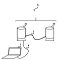
- FIG. 1 is a diagram showing a configuration of a microphone system S according to an embodiment of the present invention.
- the microphone system S includes an external device 1, a cable 2, a plurality of microphones 3 (microphones 3a, 3b), and a cable 4.
- the microphone system S is used, for example, in a state where the microphone 3a is connected to the external device 1 via the cable 4 and the microphone 3a and the microphone 3b are connected via the cable 2.
- the external device 1 is a computer such as a personal computer or a tablet.
- the external device 1 is connected to the microphone 3a via, for example, a USB interface and a cable 4.
- the external device 1 can supply power to the microphone 3a via the USB interface and the cable 4.
- the external device 1 acquires the sound signal output by the microphone 3a by executing application software that processes the sound signal acquired from the microphone 3a connected via the cable 4, for example.
- the sound signal is an electric signal having a waveform corresponding to the waveform of the sound collected by the microphone 3a.
- the cable 2 is used to connect the microphone 3a and the microphone 3b. At both ends of the cable 2, connectors that can be connected to the microphone 3a and the microphone 3b are provided.
- the shape of the connector provided on the cable 2 is arbitrary, and is, for example, a USB type C connector.
- the cable 2 transmits the electric power generated by the microphone 3a to the microphone 3b. Further, the cable 2 transmits a sound signal based on the sound collected by the microphone 3b to the microphone 3a.
- the microphone 3 is an audio device that collects sounds around the microphone 3 and converts the collected sounds into sound signals.
- the microphone 3 can be connected to the external device 1 and another microphone 3.
- Each of the plurality of microphones 3 has a plurality of operation modes that are switched depending on the connection state with the other microphone 3 and the external device 1. For example, in the case of the example shown in FIG. 1, the microphone 3a connected to the external device 1 operates in the master unit mode, and the microphone 3b connected to the microphone 3a via the cable 2 operates in the slave unit mode.
- the microphone 3a receives electric power from the external device 1 and supplies electric power to the microphone 3b via the cable 2.
- the microphone 3a synthesizes a sound signal based on the sound collected by the microphone 3a and a sound signal acquired from the microphone 3b.
- the microphone 3a outputs the synthesized sound signal to the external device 1.
- the microphone 3b is connected to the microphone 3a via a cable 2.
- the microphone 3b receives power from the microphone 3a via the cable 2.
- the microphone 3b outputs a sound signal based on the sound collected by the microphone 3b to the microphone 3a via the cable 2.
- the cable 4 connects the external device 1 and the microphone 3a.
- One end of the cable 4 is connected to the USB interface of the external device 1, and the other end is connected to the connector of the microphone 3a.
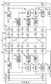
- FIG. 2 is a diagram showing an internal configuration of the microphone 3.
- FIG. 2 shows a state in which the microphone 3a is operating in the master unit mode connected to the external device 1 and the microphone 3b is operating in the slave unit mode connected to the microphone 3a, as in FIG. There is.
- the master unit mode is a mode in which power is supplied from the second connection port 32 to another microphone 3 connected via the cable 2.
- the slave unit mode is a mode in which power is supplied from another microphone 3 connected via the cable 2 via the second connection port 32.
- the solid arrow in FIG. 2 indicates that electric power is being supplied or an electric signal is being transmitted.
- the dashed arrow in FIG. 2 indicates that power is not being supplied and electrical signals are not being transmitted, even though both ends of the arrow can be electrically connected.
- the microphone 3a is connected to the external device 1 via the first connection port 31.
- the first connection port 31 is, for example, a USB connector.
- the microphone 3a receives power VBUS from the external device 1 via the first connection port 31.
- the microphone 3a and the microphone 3b are connected via a cable 2.
- the cable 2 connects the second connection port 32 of the microphone 3a and the second connection port 32 of the microphone 3b.
- a connector 2a is provided at one end of the cable 2, and a connector 2b is provided at the other end.
- the connector 2a has a terminal a1, a terminal a2, a terminal a3, a terminal a4, a terminal a5, a terminal a6, and a terminal a7.
- the connector 2b has a terminal b1, a terminal b2, a terminal b3, a terminal b4, a terminal b5, a terminal b6, and a terminal b7.
- the terminal a1 and the terminal a2 are short-circuited.
- the terminal b1 and the terminal b2 are short-circuited.
- the terminal a1 connected to the power supply of the microphone 3a and the terminal a2 connected to the connection determination voltage generation unit 34 described later are short-circuited. Further, in the cable 2, the terminal b1 connected to the power supply of the microphone 3b and the terminal b2 connected to the connection determination voltage generating unit 34 are short-circuited.
- the connector 2a and the connector 2b are connected by a conductive wire 2c.
- the terminal a1 of the connector 2a is connected to the terminal b3 of the connector 2b.
- the terminal a3 of the connector 2a is connected to the terminals b1 and b2 of the connector 2b.
- the terminal a4 of the connector 2a is connected to the terminal b5 of the connector 2b.
- the terminal a5 of the connector 2a is connected to the terminal b4 of the connector 2b.
- the terminal a6 of the connector 2a is connected to the terminal b7 of the connector 2b.
- the terminal a7 of the connector 2a is connected to the terminal b6 of the connector 2b.
- the microphone 3 includes a sound collecting unit 30, a first connection port 31, a second connection port 32, a power generation unit 33, a connection determination voltage generation unit 34, a mode determination voltage generation unit 35, and a determination unit 36. , A selection unit 37, a slave unit signal output unit 38, and a composite signal output unit 39.
- the sound collecting unit 30 collects the sound around the microphone 3.
- the sound collecting unit 30 includes an electroacoustic conversion element, and converts the collected sound into a sound signal.
- the sound collecting unit 30 outputs a sound signal to the selection unit 37.
- the first connection port 31 has a terminal D1 and a terminal D2.
- the terminal D1 is connected to the power supply terminal in the external device 1 via the cable 4.
- the terminal D2 is connected to the sound input terminal of the external device 1 via the cable 4.
- the terminal D1 of the microphone 3a is connected to the power generating unit 33 of the microphone 3a and the terminal A4 of the microphone 3a.
- the terminal D2 of the microphone 3a is connected to the composite signal output unit 39 of the microphone 3a.
- the terminals D1 and D2 of the microphone 3b are in an open state.
- the second connection port 32 has a terminal A1, a terminal A2, a terminal A3, a terminal A4, a terminal A5, a terminal A6, and a terminal A7. These terminals are used to connect to another microphone 3 via the cable 2.
- Terminal A1 is connected to the output side of the power VCS in the power generation unit 33.
- the electric power VCS is used as electric power for operating each part of the microphone 3.
- the terminal A1 of the microphone 3a is connected to the terminal A3 of the microphone 3b via the terminal a1 of the connector 2a and the terminal b3 of the connector 2b.
- the terminal A3 of the microphone 3b is connected to the connection determination voltage generating unit 34 of the microphone 3b.
- the electric power VCS input to the terminal A3 of the microphone 3b is used as electric power for operating each part of the microphone 3b.
- the terminal A1 of the microphone 3a is connected to the terminal A2 of the microphone 3a via the terminal a1 of the connector 2a and the terminal a2 of the connector 2a.
- the terminal A2 of the microphone 3a is connected to the connection determination voltage generation unit 34 of the microphone 3a.
- the power generation unit 33 of the microphone 3a supplies the generated power VCS to the connection determination voltage generation unit 34 of the microphone 3a and the connection determination voltage generation unit 34 of the microphone 3b.
- the power generating unit 33 of the microphone 3b does not generate the power VCS. Therefore, the connection determination voltage generation unit 34 of the microphone 3a does not receive power from the microphone 3b via the terminal A3 of the microphone 3a.
- Terminal A4 is connected to terminal D1.
- the terminal A5 is connected to the input side of the mode determination voltage generation unit 35.
- the terminal A4 of the microphone 3a is connected to the terminal A5 of the microphone 3b via the terminal a4 of the connector 2a and the terminal b5 of the connector 2b.
- the terminal A5 of the microphone 3b is connected to the mode determination voltage generating unit 35 of the microphone 3b. Therefore, the power VBUS is input to the mode determination voltage generation unit 35 of the microphone 3b via the terminal A4 of the microphone 3a, the terminal a4 of the connector 2a, the terminal b5 of the connector 2b, and the terminal B5 of the microphone 3b.
- the terminal D1 of the microphone 3b is not connected to the external device 1. Therefore, the power VBUS is not input to the mode determination voltage generation unit 35 of the microphone 3a.
- Terminal A6 is connected to the output side of the slave unit signal output unit 38.
- the terminal A7 is connected to the input side of the composite signal output unit 39.
- the terminal A6 of the microphone 3b is connected to the composite signal output unit 39 of the microphone 3a via the terminal b6 of the connector 2b, the terminal a7 of the connector 2a, and the terminal A7 of the microphone 3a. Therefore, the sound signal output by the handset signal output unit 38 of the microphone 3b is a composite signal of the microphone 3a via the terminal A6 of the microphone 3b, the terminal b6 of the connector 2b, the terminal a7 of the connector 2a, and the terminal A7 of the microphone 3a. It is input to the output unit 39.
- the selection unit 37 which will be described later, does not input the sound signal to the slave unit signal output unit 38. Therefore, since the slave unit signal output unit 38 of the microphone 3a does not output the sound signal, the sound signal is not input to the composite signal output unit 39 of the microphone 3b. The details of the operation of the composite signal output unit 39 will be described later.
- the power generation unit 33 of the microphone 3a receives the power VBUS from the external device 1 via the terminal D1.
- the power generation unit 33 of the microphone 3a generates the power VCS, which is the second power to be supplied to the microphone 3b via the cable 2, based on the power VBUS, which is the first power supplied from the external device 1.
- the power generation unit 33 has, for example, at least one of a protection circuit and a regulator.
- the power generation unit 33 of the microphone 3a supplies the power VCS to the connection determination voltage generation unit 34 of the microphone 3a and the connection determination voltage generation unit 34 of the microphone 3b via the cable 2.
- the power generation unit 33 of the microphone 3b does not operate because it does not receive power from the external device 1. Therefore, the power generation unit 33 of the microphone 3b does not supply the power VCS to the connection determination voltage generation unit 34 of the microphone 3a and the connection determination voltage generation unit 34 of the microphone 3b.
- the connection determination voltage generation unit 34 receives the power VCS generated by the power generation unit 33 via the cable 2.
- the connection determination voltage generation unit 34 generates different connection determination voltages depending on the supplied power VCS, depending on whether the cable 2 is connected or not.
- the connection determination voltage generation unit 34 outputs the generated connection determination voltage to the determination unit 36.
- connection determination voltage generation unit 34 of the microphone 3a receives the power VCS generated by the power generation unit 33 of the microphone 3a via the terminals A1 and A2 of the connector 2a. Since the power generating unit 33 of the microphone 3b does not generate the power VCS, the connection determination voltage generating unit 34 of the microphone 3a does not receive the power VCS from the power generating unit 33 of the microphone 3b via the cable 2.
- connection determination voltage generation unit 34 of the microphone 3b receives the power VCS generated by the power generation unit 33 of the microphone 3a via the cable 2.
- the connection determination voltage generation unit 34 of the microphone 3b does not receive the power VCS from the power generation unit 33 of the microphone 3b.
- connection determination voltage generation unit 34 outputs a connection determination voltage (for example, a high level voltage) indicating that the cable 2 is connected when the power VCS is received via the terminal A2 or the terminal A3.
- connection determination voltage generation unit 34 outputs a connection determination voltage (for example, a low level voltage) indicating that the cable 2 is not connected when the power VCS is not received via the terminal A2 or the terminal A3. The details of the connection determination voltage generation unit 34 will be described later.
- the mode determination voltage generation unit 35 generates different mode determination voltages depending on whether the electric power (for example, VBUS) is supplied via the cable 2 and the electric power is not supplied via the cable 2. In the example shown in FIG. 2, the mode determination voltage generation unit 35 generates a mode determination voltage indicating whether or not power VBUS is received from another microphone 3 via the cable 2. The mode determination voltage generation unit 35 outputs the generated mode determination voltage to the determination unit 36.
- the electric power for example, VBUS
- the mode determination voltage generation unit 35 of the microphone 3b receives the power VBUS output from the terminal A4 of the microphone 3a via the cable 2 and the terminal A5 of the microphone 3b. On the other hand, since the power VBUS is not output from the terminal A4 of the microphone 3b, the mode determination voltage generation unit 35 of the microphone 3a does not receive the power VBUS via the terminal A5 of the microphone 3a.
- the mode determination voltage generation unit 35 outputs a mode determination voltage (for example, a high level voltage) indicating that power is being supplied when the power VBUS is received via the terminal A5.
- the mode determination voltage generation unit 35 outputs a mode determination voltage (for example, a low level voltage) indicating that the power is not supplied when the power VBUS is not received via the terminal A5.
- the details of the mode determination voltage generating unit 35 will be described later.
- the determination unit 36 has, for example, a CPU (Central Processing Unit). The determination unit 36 determines whether the microphone 3 operates in the master unit mode or the slave unit mode by executing a program stored in the memory, for example.
- a CPU Central Processing Unit
- the determination unit 36 is in the master unit mode when power is being supplied from the external device 1 via the terminal D1 of the first connection port 31 and the cable 2 is connected to the second connection port 32. Judged to work with. On the other hand, the determination unit 36 is a child when power is not supplied from the external device 1 via the terminal D1 of the first connection port 31 and the cable 2 is connected to the second connection port 32. Judged to operate in machine mode.
- the determination unit 36 determines whether or not the cable 2 is connected based on the connection determination voltage input from the connection determination voltage generation unit 34. Further, the determination unit 36 determines whether the microphone 3 operates in the master unit mode or the slave unit mode based on the mode determination voltage input from the mode determination voltage generation unit 35. The determination unit 36 determines whether the microphone 3 operates in the master unit mode or the slave unit mode based on, for example, a combination of the connection determination voltage and the mode determination voltage.
- the determination unit 36 determines the microphone 3 Judges that it operates in the master unit mode. On the other hand, the determination unit 36 is a microphone when the mode determination voltage indicates that the power VBUS is being supplied via the cable 2 and the connection determination voltage indicates that the cable 2 is connected. It is determined that 3 operates in the slave unit mode.
- the determination unit 36 determines a route for outputting the sound signal input from the sound collection unit 30 based on the determination result of whether the microphone 3 operates as the master unit mode or the slave unit mode.
- the determination unit 36 notifies the selection unit 37 of the determined route. Specifically, when the determination unit 36 determines that the microphone 3 operates as the master unit mode, the determination unit 36 instructs the selection unit 37 to output the sound signal input from the sound collection unit 30 to the composite signal output unit 39. .. On the other hand, when the determination unit 36 determines that the microphone 3 operates in the slave unit mode, the determination unit 36 instructs the selection unit 37 to output the sound signal input from the sound collection unit 30 to the slave unit signal output unit 38.
- the selection unit 37 switches whether to output the sound signal input from the sound collection unit 30 to the slave unit signal output unit 38 or the composite signal output unit 39 based on the instruction acquired from the determination unit 36.
- the selection unit 37 of the microphone 3a outputs the sound signal input from the sound collecting unit 30 of the microphone 3a to the composite signal output unit 39 in response to the instruction for operating in the master unit mode from the determination unit 36. do.
- the selection unit 37 of the microphone 3b sends the sound signal input from the sound collecting unit 30 of the microphone 3b to the slave unit signal output unit 38 in response to the instruction for operating in the slave unit mode from the determination unit 36. Output.
- the slave unit signal output unit 38 of the microphone 3b operating in the slave unit mode receives the slave unit sound signal from the selection unit 37 of the microphone 3b. Therefore, the slave unit signal output unit 38 of the microphone 3b outputs the slave unit sound signal to the composite signal output unit 39 of the microphone 3a operating in the master unit mode via the terminal A6.
- the slave unit signal output unit 38 of the microphone 3a operating in the master unit mode does not receive the slave unit sound signal from the selection unit 37 of the microphone 3a. Therefore, the slave unit signal output unit 38 of the microphone 3a does not output the slave unit sound signal via the terminal A6.
- the combined signal output unit 39 synthesizes the master unit sound signal input via the sound collecting unit 30 and the slave unit sound signal received from the slave unit signal output unit 38 of the microphone 3b operating in the slave unit mode.
- the combined signal output unit 39 outputs the combined sound signal to the external device 1 via the terminal D2.
- the combined signal output unit 39 of the microphone 3a synthesizes the slave unit sound signal which is an analog signal and the master unit sound signal which is an analog signal, and converts the combined sound signal into a digital synthesized sound signal.
- the composite signal output unit 39 outputs the digital composite sound signal to the external device 1 via the terminal D2 of the microphone 3a.
- the combined signal output unit 39 of the microphone 3b does not operate because it does not receive a sound signal from the slave unit signal output unit 38 and the selection unit 37 of the microphone 3a.
- the microphone 3a is a sound obtained by synthesizing the sound collected by the sound collecting unit 30 of the microphone 3b and the sound collected by the sound collecting unit 30 of the microphone 3a.
- the digitally synthesized sound signal corresponding to is output to the external device 1.
- the power consumption required for the composite signal output unit 39 to synthesize an analog sound signal is smaller than the power consumption required for synthesizing a digital sound signal. Therefore, the composite signal output unit 39 consumes power by generating a digital composite sound signal after synthesizing the analog sound signal input from the microphone 3b and the analog sound signal input from the sound collection unit 30. It can be suppressed.
- the composite signal output unit 39 can generate a digital composite sound signal by the power VBUS supplied from the external device 1 via the USB interface.
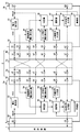
- FIG. 3 is a diagram showing a configuration when the microphone 3a operates in the single mode.
- the microphone system S is different from the microphone system S shown in FIG. 2 in that the microphone 3a and the microphone 3b are not connected via the cable 2, and is the same in other respects.
- the microphone 3b does not operate because it is not connected to the microphone 3a via the cable 2.
- the connection determination voltage generation unit 34 of the microphone 3a When the cable 2 is not connected to the microphone 3a, the terminal A1 and the terminal A2 of the microphone 3a are not short-circuited. Therefore, the power VCS generated by the power generation unit 33 of the microphone 3a is not input to the connection determination voltage generation unit 34 of the microphone 3a via the terminal A2. Further, the power VCS is not input to the connection determination voltage generation unit 34 via the terminal A3. As a result, the connection determination voltage generation unit 34 of the microphone 3a generates a connection determination voltage indicating that the cable 2 is not connected.
- the determination unit 36 of the microphone 3a determines that the mode is used without being connected to another microphone (for example, the microphone 3b). The determination unit 36 of the microphone 3a notifies the selection unit 37 of the microphone 3a that the microphone 3a operates in the single mode.
- the selection unit 37 of the microphone 3a When the selection unit 37 of the microphone 3a receives a notification from the determination unit 36 that it operates in the single mode, the selection unit 37 outputs the sound signal input from the sound collection unit 30 of the microphone 3a to the composite signal output unit 39.
- the combined signal output unit 39 outputs the sound signal input via the selection unit 37 to the terminal D2 without synthesizing it with other sound signals.
- the microphone 3a By operating the microphone 3a in this way, when the cable 2 is not connected, the microphone 3a outputs a digital sound signal corresponding to the sound collected by the sound collecting unit 30 to the external device 1.
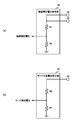
- FIG. 4 is a diagram showing an example of a voltage generation unit of the connection determination voltage generation unit 34 and the mode determination voltage generation unit 35.
- FIG. 4A shows an example of the voltage generating unit of the connection determination voltage generating unit 34
- FIG. 4B shows an example of the voltage generating unit of the mode determination voltage generating unit 35.
- the connection determination voltage generation unit 34 shown in FIG. 4A has a resistor R1 and a resistor R2.
- the resistor R1 and the resistor R2 are connected in series.
- One end of the resistor R1 is connected to the terminals A2 and A3, and the other end is connected to the resistor R2.
- One end of the resistor R2 is connected to the resistor R1 and the other end is connected to the ground.
- the connection determination voltage generation unit 34 outputs a voltage obtained by dividing the voltage input from the terminal A2 or the terminal A3 by the resistors R1 and R2 as the connection determination voltage.
- connection determination voltage generation unit 34 When power is not supplied from the terminals A2 and A3, the connection determination voltage generation unit 34 outputs a voltage of 0 volt as the connection determination voltage. On the other hand, when power is supplied from the terminal A2 or the terminal A3, the connection determination voltage generation unit 34 outputs the voltage represented by the following equation (1) as the connection determination voltage.
- V1 in the formula (1) is the voltage of the terminal A2 or the terminal A3.
- the mode determination voltage generation unit 35 shown in FIG. 4B has a resistor R3 and a resistor R4.
- the resistor R3 and the resistor R4 are connected in series. One end of the resistor R3 is connected to the terminal A5, and the other end is connected to the resistor R4. One end of the resistor R4 is connected to the resistor R3 and the other end is connected to the ground.
- the mode determination voltage generation unit 35 outputs the voltage obtained by dividing the voltage input from the terminal A5 by the resistors R3 and R4 as the mode determination voltage.
- the mode determination voltage generation unit 35 When power is not supplied from the terminal A5, the mode determination voltage generation unit 35 outputs a voltage of 0 volt as a mode determination voltage. On the other hand, when power is supplied from the terminal A5, the mode determination voltage generation unit 35 outputs the voltage represented by the following equation (2) as the mode determination voltage.
- R4 / (R3 + R4) x V2 (2) V2 in the formula (2) is the voltage of the terminal A5.
- the mode determination voltage generation unit 35 outputs different mode determination voltages depending on whether or not the power VBUS is supplied via the terminal A5.
- the mode determination voltage generation unit 35 may output different mode determination voltages depending on whether or not other power is supplied.
- the other power is, for example, power VCS.
- the mode determination voltage generation unit 35 outputs a different mode determination voltage depending on whether or not the power VCS is supplied via the terminal A5. You may.
- the configuration of the connection determination voltage generation unit 34 and the mode determination voltage generation unit 35 is not limited to the configuration shown in FIG. 4, and may be configured by other circuits such as a logic circuit.
- FIG. 5 is a diagram showing a determination result of the determination unit 36 based on the connection determination voltage and the mode determination voltage.
- “H” of the connection determination voltage indicates that the value of the connection determination voltage is a high level voltage equal to or higher than the first threshold value.
- “L” of the connection determination voltage indicates that the value of the connection determination voltage is a low level voltage less than the first threshold value.
- “H” of the mode determination voltage indicates that the value of the mode determination voltage is a high level voltage equal to or higher than the second threshold value.
- “L” of the mode determination voltage indicates that the value of the mode determination voltage is a low level voltage less than the second threshold value.
- the first threshold value is used to determine the connection state of the cable 2.
- the first threshold value is a value calculated by the equation (1) when, for example, the voltage based on the power VCS input from the terminal A2 or the terminal A3 is the assumed minimum voltage. This assumed minimum voltage is the minimum voltage in the range in which the voltage of the terminal A2 or the terminal A3 can fluctuate due to variations in the power generating unit 33, temperature changes, or the like.
- the second threshold is used to determine the operating mode of the microphone 3.
- the second threshold value is a value calculated by the equation (2) when, for example, the voltage based on the power VBUS input from the terminal A5 is the assumed minimum voltage. This assumed minimum voltage is the minimum voltage in a range in which the voltage of the terminal A5 can fluctuate due to variations in the voltage output by the external device 1, variations in the cable 4, temperature changes, and the like.
- the determination unit 36 determines that the operation mode of the microphone 3 is the master unit mode. When the connection determination voltage is “H” and the mode determination voltage is “H”, the determination unit 36 determines that the operation mode of the microphone 3 is the slave unit mode. When the connection determination voltage is “L”, the determination unit 36 determines that the operation mode of the microphone 3 is the independent mode.
- the determination unit 36 When the connection determination voltage is “L” and the mode determination voltage is "H”, it is possible that the cable 2 is disconnected between the terminals a1 and a2, so that the determination unit 36 is abnormal. Determined to be in a state. In this case, the determination unit 36 transmits abnormality notification data for displaying that an abnormality has occurred in the external device 1 to the external device 1, or displays that an abnormality has occurred in an indicator (not shown) included in the microphone 3a. You may do it. The determination unit 36 may display information indicating which operation mode of the master unit mode, the slave unit mode, and the independent mode is operating on the indicator.
- FIG. 6 is a diagram showing a flowchart of the operation of the determination unit 36.
- the determination unit 36 acquires the connection determination voltage from the connection determination voltage generation unit 34 (S11). When the acquired connection determination voltage is less than the first threshold value (NO in S12), the determination unit 36 determines that the microphone 3 operates in the single mode (S13). Then, the determination unit 36 instructs the selection unit 37 to output the sound signal input from the sound collection unit 30 to the composite signal output unit 39 (S17). On the other hand, when the connection determination voltage is equal to or higher than the first threshold value (YES in S12), the determination unit 36 acquires the mode determination voltage from the mode determination voltage generation unit 35 (S14).
- the determination unit 36 determines that the operation mode of the microphone 3 is the master unit mode (S16). Then, the determination unit 36 instructs the selection unit 37 to output the sound signal input from the sound collection unit 30 to the composite signal output unit 39 (S17). On the other hand, when the acquired mode determination voltage is equal to or higher than the second threshold value (YES in S15), the determination unit 36 determines that the operation mode of the microphone 3 is the slave unit mode (S18). Then, the determination unit 36 instructs the selection unit 37 to output the sound signal input from the sound collection unit 30 to the slave unit signal output unit 38 (S19).
- the order in which the determination unit 36 executes the processing is not limited to the order shown in FIG.
- the determination unit 36 may execute the determination based on the mode determination voltage before the determination based on the connection determination voltage.
- the terminals a3 and b1, the terminals a5 and b4, the terminals a6 and b7, and the terminals b1 and b2 are not connected.
- the connector 2a is a connector on the side connected to the microphone 3a operated in the master unit mode
- the connector 2b functions as a connector on the side connected to the microphone 3b operated in the slave unit mode.
- the connector 2a and the connector 2b are different so that the user of the microphone system S connects the connector 2a to the microphone 3a used in the master unit mode and connects the connector 2b to the microphone 3b used in the slave unit mode.
- the connector 2a is marked with a mark (for example, M) indicating that it is for a master unit
- the connector 2b is marked with a mark (for example, S) indicating that it is for a slave unit.
- FIG. 7 is a diagram showing a state in which the cable 2V is connected with the correct polarity.
- the microphone 3a operates in the master unit mode and the microphone 3b operates in the slave unit mode, as in the case shown in FIG.
- FIG. 8 is a diagram showing a state in which the cable 2V is connected with the wrong polarity.
- the connection determination voltage becomes “L”.
- the mode determination voltage is also set to “L”.
- the determination unit 36 determines that the microphone 3a is in the independent mode. In this case, the determination unit displays on the indicator that it is operating in the independent mode. Since no power is supplied to the microphone 3b, the microphone 3b does not operate.
- the terminal b1 and the terminal b2 may be connected in the cable 2V shown in FIGS. 7 and 8.
- the power VCS is supplied to the connection determination voltage generation unit 34, so that the connection determination voltage becomes “H” and the determination unit 36 determines that the master unit mode is in use. ..
- the combined signal output unit 39 operates in a substantially independent mode.
- the microphone 3 is based on the mode determination voltage generation unit 35 that generates the mode determination voltage, the connection determination voltage generation unit 34 that generates the connection determination voltage, and the mode determination voltage and the connection determination voltage. It has a determination unit 36 for determining an operation mode. Then, the determination unit 36 determines the operation mode of the microphone 3 based on the mode determination voltage and the connection determination voltage. Based on the determination result of the determination unit 36, the selection unit 37 determines whether to output the sound signal based on the sound collected by the sound collection unit 30 to the other microphone 3 or the external device 1.
- the microphone system S can connect a plurality of microphones with a simple configuration without using a conversion device other than the plurality of microphones 3. For example, when the microphone 3a and the microphone 3b are connected via the cable 2 and the microphone 3a is connected to the external device 1, the microphone system S inputs the sound collected by the plurality of microphones 3 to the external device 1. can do. As a result, the user can easily connect the plurality of microphones 3 and the external device 1.
- the microphone 3 of the present invention determines the operation mode according to the connection state of the cable to the microphone 3, and determines whether to output the sound signal to the other microphone 3 or the external device 1.
- the microphone 3 determines, for example, that it operates in the master unit mode when the cable 4 is connected to the external device 1. Therefore, it is not necessary for the user to switch the switch provided on the microphone 3 depending on whether the microphone 3 is used as a master unit or a slave unit. In addition, it is difficult for the user to operate the microphone 3 operated in the slave unit mode in the master unit mode. Further, in the microphone system S, since it is not necessary to connect the microphone 3 to the external power supply, there is no possibility that the power supply is erroneously input.
- the external device 1 and the microphone 3a used as the master unit are connected by the cable 4, and the microphone 3a and the microphone 3b used as the slave unit are connected by the cable 2.
- Power is supplied to the plurality of microphones 3.
- the user does not need to connect the power cable and the microphone 3 for example, so that the power cable is not erroneously connected to the microphone 3b used as the slave unit.
- External device Cable 3
- Microphone 30
- Sound collecting unit 31
- First connection port 32
- Second connection port 33
- Power generation unit 34
- Connection judgment voltage generation unit 35
- Mode judgment voltage generation unit 36
- Judgment unit 37
- Selection unit 38
- Slave unit signal output unit 39 Synthetic signal output section
Landscapes
- Physics & Mathematics (AREA)
- Engineering & Computer Science (AREA)
- Acoustics & Sound (AREA)
- Signal Processing (AREA)
- Health & Medical Sciences (AREA)
- General Health & Medical Sciences (AREA)
- Otolaryngology (AREA)
- Circuit For Audible Band Transducer (AREA)
Abstract
L'invention concerne un microphone 3 comprenant : un premier port de connexion 31 destiné à être connecté à un dispositif externe 1 ; un second port de connexion 32 destiné à être connecté à un autre microphone 3 par l'intermédiaire d'un câble 2 ; et une unité de détermination 36 qui détermine un mode courant en tant que mode d'unité maître dans lequel de l'énergie est fournie par le second port de connexion 32 à l'autre microphone 3 connecté par l'intermédiaire du câble 2 lorsque le câble 2 est connecté au second port de connexion dans un état dans lequel l'énergie est fournie par le dispositif externe 1 par l'intermédiaire du premier port de connexion 31, et détermine le mode courant en tant que mode d'unité esclave dans lequel l'énergie est fournie et reçue par l'intermédiaire du second port de connexion 32 à partir de l'autre microphone 3 connecté par l'intermédiaire du câble 2 lorsque le câble 2 est connecté au second port de connexion 32 dans un état dans lequel l'énergie n'est pas fournie par le dispositif externe 1 par l'intermédiaire du premier port de connexion 31.
Priority Applications (2)
| Application Number | Priority Date | Filing Date | Title |
|---|---|---|---|
| JP2022512063A JP7634287B2 (ja) | 2020-03-31 | 2021-03-25 | マイクロフォン及びマイクロフォンシステム |
| US17/930,808 US12149898B2 (en) | 2020-03-31 | 2022-09-09 | Microphone and microphone system |
Applications Claiming Priority (2)
| Application Number | Priority Date | Filing Date | Title |
|---|---|---|---|
| JP2020063306 | 2020-03-31 | ||
| JP2020-063306 | 2020-03-31 |
Related Child Applications (1)
| Application Number | Title | Priority Date | Filing Date |
|---|---|---|---|
| US17/930,808 Continuation US12149898B2 (en) | 2020-03-31 | 2022-09-09 | Microphone and microphone system |
Publications (1)
| Publication Number | Publication Date |
|---|---|
| WO2021200536A1 true WO2021200536A1 (fr) | 2021-10-07 |
Family
ID=77929885
Family Applications (1)
| Application Number | Title | Priority Date | Filing Date |
|---|---|---|---|
| PCT/JP2021/012528 Ceased WO2021200536A1 (fr) | 2020-03-31 | 2021-03-25 | Microphone et système de microphone |
Country Status (3)
| Country | Link |
|---|---|
| US (1) | US12149898B2 (fr) |
| JP (1) | JP7634287B2 (fr) |
| WO (1) | WO2021200536A1 (fr) |
Families Citing this family (1)
| Publication number | Priority date | Publication date | Assignee | Title |
|---|---|---|---|---|
| TWI850788B (zh) * | 2022-10-06 | 2024-08-01 | 宏碁股份有限公司 | 電腦系統及其聲音訊號的處理方法 |
Citations (2)
| Publication number | Priority date | Publication date | Assignee | Title |
|---|---|---|---|---|
| JP2006140930A (ja) * | 2004-11-15 | 2006-06-01 | Sony Corp | マイクシステムおよびマイク装置 |
| JP2012104991A (ja) * | 2010-11-09 | 2012-05-31 | Audio Technica Corp | マイクロホンおよびマイクロホン装置 |
Family Cites Families (2)
| Publication number | Priority date | Publication date | Assignee | Title |
|---|---|---|---|---|
| JP2005039531A (ja) | 2003-07-15 | 2005-02-10 | Audio Technica Corp | マイクロホン |
| JP2010251859A (ja) * | 2009-04-10 | 2010-11-04 | Toshiba Corp | 携帯端末 |
-
2021
- 2021-03-25 JP JP2022512063A patent/JP7634287B2/ja active Active
- 2021-03-25 WO PCT/JP2021/012528 patent/WO2021200536A1/fr not_active Ceased
-
2022
- 2022-09-09 US US17/930,808 patent/US12149898B2/en active Active
Patent Citations (2)
| Publication number | Priority date | Publication date | Assignee | Title |
|---|---|---|---|---|
| JP2006140930A (ja) * | 2004-11-15 | 2006-06-01 | Sony Corp | マイクシステムおよびマイク装置 |
| JP2012104991A (ja) * | 2010-11-09 | 2012-05-31 | Audio Technica Corp | マイクロホンおよびマイクロホン装置 |
Also Published As
| Publication number | Publication date |
|---|---|
| US20230007391A1 (en) | 2023-01-05 |
| JPWO2021200536A1 (fr) | 2021-10-07 |
| JP7634287B2 (ja) | 2025-02-21 |
| US12149898B2 (en) | 2024-11-19 |
Similar Documents
| Publication | Publication Date | Title |
|---|---|---|
| US7589536B2 (en) | Systems and methods for determining the configuration of electronic connections | |
| EP2597844A1 (fr) | Procédé et dispositif permettant d'autoriser le partage d'une interface micro-usb entre un câble d'écouteur et un câble usb | |
| JP5058083B2 (ja) | インタフェース装置 | |
| CN114069801A (zh) | 快充连接电路、快充连接装置及充电控制方法 | |
| TW201351150A (zh) | 手持式電子裝置與週邊擴充裝置 | |
| JP5330348B2 (ja) | 携帯マルチメディア装置の急速充電に適合されたマザーボード | |
| KR20190054428A (ko) | 외부 액세서리 연결에 따른 마이크 제어 장치 및 방법 | |
| JP2001067159A (ja) | インターフェース切替装置 | |
| JP7634287B2 (ja) | マイクロフォン及びマイクロフォンシステム | |
| US11810541B2 (en) | Electronic musical instrument, power control device for electronic musical instrument, and power control method | |
| JP2013251728A (ja) | コネクタ装置、及び、電子装置 | |
| CN114077565A (zh) | 识别电路、系统控制电路、接入电路、接口设备 | |
| CN114604173A (zh) | 检测系统、t-box及车辆 | |
| JP6533123B2 (ja) | 充電システム | |
| CN103312842B (zh) | 用于附件检测和控制的终端、附件及系统 | |
| JP2017085253A (ja) | 情報処理装置 | |
| JP6835434B2 (ja) | 電子機器 | |
| CN103001261A (zh) | 广用型usb充电器 | |
| JP5211099B2 (ja) | 変換アダプタ及び電子機器 | |
| JP2002084652A (ja) | 保護継電装置の試験装置 | |
| KR101167912B1 (ko) | 이어폰 | |
| CN113485088B (zh) | 一种键盘切换电路和键盘切换电路的控制方法 | |
| JP7864104B2 (ja) | 電源供給装置、電源供給システム、電源供給制御方法、及び、電源供給制御プログラム | |
| JP2004153614A (ja) | 音声信号中継装置 | |
| JP7613087B2 (ja) | 楽器用信号出力装置、楽器用信号出力装置における楽器接続端子の極性の制御方法 |
Legal Events
| Date | Code | Title | Description |
|---|---|---|---|
| 121 | Ep: the epo has been informed by wipo that ep was designated in this application |
Ref document number: 21781853 Country of ref document: EP Kind code of ref document: A1 |
|
| ENP | Entry into the national phase |
Ref document number: 2022512063 Country of ref document: JP Kind code of ref document: A |
|
| NENP | Non-entry into the national phase |
Ref country code: DE |
|
| 122 | Ep: pct application non-entry in european phase |
Ref document number: 21781853 Country of ref document: EP Kind code of ref document: A1 |