WO2021200546A1 - Dispositif de fabrication de plaque d'électrode et procédé de fabrication de plaque d'électrode - Google Patents
Dispositif de fabrication de plaque d'électrode et procédé de fabrication de plaque d'électrode Download PDFInfo
- Publication number
- WO2021200546A1 WO2021200546A1 PCT/JP2021/012559 JP2021012559W WO2021200546A1 WO 2021200546 A1 WO2021200546 A1 WO 2021200546A1 JP 2021012559 W JP2021012559 W JP 2021012559W WO 2021200546 A1 WO2021200546 A1 WO 2021200546A1
- Authority
- WO
- WIPO (PCT)
- Prior art keywords
- electrode plate
- tension
- coated
- transport
- compression roll
- Prior art date
- Legal status (The legal status is an assumption and is not a legal conclusion. Google has not performed a legal analysis and makes no representation as to the accuracy of the status listed.)
- Ceased
Links
Images
Classifications
-
- H—ELECTRICITY
- H01—ELECTRIC ELEMENTS
- H01M—PROCESSES OR MEANS, e.g. BATTERIES, FOR THE DIRECT CONVERSION OF CHEMICAL ENERGY INTO ELECTRICAL ENERGY
- H01M4/00—Electrodes
- H01M4/02—Electrodes composed of, or comprising, active material
- H01M4/13—Electrodes for accumulators with non-aqueous electrolyte, e.g. for lithium-accumulators; Processes of manufacture thereof
- H01M4/139—Processes of manufacture
-
- B—PERFORMING OPERATIONS; TRANSPORTING
- B30—PRESSES
- B30B—PRESSES IN GENERAL
- B30B3/00—Presses characterised by the use of rotary pressing members, e.g. rollers, rings, discs
-
- B—PERFORMING OPERATIONS; TRANSPORTING
- B65—CONVEYING; PACKING; STORING; HANDLING THIN OR FILAMENTARY MATERIAL
- B65H—HANDLING THIN OR FILAMENTARY MATERIAL, e.g. SHEETS, WEBS, CABLES
- B65H23/00—Registering, tensioning, smoothing or guiding webs
- B65H23/04—Registering, tensioning, smoothing or guiding webs longitudinally
- B65H23/18—Registering, tensioning, smoothing or guiding webs longitudinally by controlling or regulating the web-advancing mechanism, e.g. mechanism acting on the running web
-
- H—ELECTRICITY
- H01—ELECTRIC ELEMENTS
- H01M—PROCESSES OR MEANS, e.g. BATTERIES, FOR THE DIRECT CONVERSION OF CHEMICAL ENERGY INTO ELECTRICAL ENERGY
- H01M10/00—Secondary cells; Manufacture thereof
- H01M10/04—Construction or manufacture in general
-
- H—ELECTRICITY
- H01—ELECTRIC ELEMENTS
- H01M—PROCESSES OR MEANS, e.g. BATTERIES, FOR THE DIRECT CONVERSION OF CHEMICAL ENERGY INTO ELECTRICAL ENERGY
- H01M10/00—Secondary cells; Manufacture thereof
- H01M10/04—Construction or manufacture in general
- H01M10/0404—Machines for assembling batteries
- H01M10/0409—Machines for assembling batteries for cells with wound electrodes
-
- H—ELECTRICITY
- H01—ELECTRIC ELEMENTS
- H01M—PROCESSES OR MEANS, e.g. BATTERIES, FOR THE DIRECT CONVERSION OF CHEMICAL ENERGY INTO ELECTRICAL ENERGY
- H01M10/00—Secondary cells; Manufacture thereof
- H01M10/05—Accumulators with non-aqueous electrolyte
- H01M10/052—Li-accumulators
-
- H—ELECTRICITY
- H01—ELECTRIC ELEMENTS
- H01M—PROCESSES OR MEANS, e.g. BATTERIES, FOR THE DIRECT CONVERSION OF CHEMICAL ENERGY INTO ELECTRICAL ENERGY
- H01M4/00—Electrodes
- H01M4/02—Electrodes composed of, or comprising, active material
- H01M4/04—Processes of manufacture in general
-
- H—ELECTRICITY
- H01—ELECTRIC ELEMENTS
- H01M—PROCESSES OR MEANS, e.g. BATTERIES, FOR THE DIRECT CONVERSION OF CHEMICAL ENERGY INTO ELECTRICAL ENERGY
- H01M4/00—Electrodes
- H01M4/02—Electrodes composed of, or comprising, active material
- H01M4/04—Processes of manufacture in general
- H01M4/0402—Methods of deposition of the material
- H01M4/0404—Methods of deposition of the material by coating on electrode collectors
-
- H—ELECTRICITY
- H01—ELECTRIC ELEMENTS
- H01M—PROCESSES OR MEANS, e.g. BATTERIES, FOR THE DIRECT CONVERSION OF CHEMICAL ENERGY INTO ELECTRICAL ENERGY
- H01M4/00—Electrodes
- H01M4/02—Electrodes composed of, or comprising, active material
- H01M4/04—Processes of manufacture in general
- H01M4/043—Processes of manufacture in general involving compressing or compaction
- H01M4/0435—Rolling or calendering
-
- Y—GENERAL TAGGING OF NEW TECHNOLOGICAL DEVELOPMENTS; GENERAL TAGGING OF CROSS-SECTIONAL TECHNOLOGIES SPANNING OVER SEVERAL SECTIONS OF THE IPC; TECHNICAL SUBJECTS COVERED BY FORMER USPC CROSS-REFERENCE ART COLLECTIONS [XRACs] AND DIGESTS
- Y02—TECHNOLOGIES OR APPLICATIONS FOR MITIGATION OR ADAPTATION AGAINST CLIMATE CHANGE
- Y02E—REDUCTION OF GREENHOUSE GAS [GHG] EMISSIONS, RELATED TO ENERGY GENERATION, TRANSMISSION OR DISTRIBUTION
- Y02E60/00—Enabling technologies; Technologies with a potential or indirect contribution to GHG emissions mitigation
- Y02E60/10—Energy storage using batteries
Definitions
- the present disclosure relates to an electrode plate manufacturing apparatus and an electrode plate manufacturing method.
- an electrode plate used for a lithium ion secondary battery or the like has a structure in which an electrode active material is coated on the surface of a base material (current collector) made of aluminum foil, copper foil, or the like. Further, the electrode plate has an uncoated portion on which the electrode active material is not coated on the surface of the base material.
- the uncoated portion functions as, for example, a current collecting tab. That is, the electrode plate has a coated portion in which the base material and the electrode active material layer are laminated, and a non-coated portion composed of only the base material.
- the electrode active material is continuously applied to the central portion in the width direction of the base material while transporting a long base material, and extends in the transport direction at the central portion of the base material.
- a method of forming a long electrode plate having a coated portion and an uncoated portion extending in the transport direction at the end portion of the base material is known.
- the coated portion of the electrode plate is compressed by a roll press or the like for the purpose of increasing the density of the electrode active material and making the thickness uniform.
- the electrode plate after compressing the coated portion is wound into a roll and transferred to the next step.
- the electrode plates are separated into a plurality of pieces, laminated with a separator sandwiched between them, and sealed in an outer can.
- the coated portion when the coated portion is compressed, only the electrode active material is compressed and the base material constituting the coated portion is not rolled. However, in reality, when the coated portion is compressed, the base material is also rolled. On the other hand, since the thickness of the uncoated portion is thinner than the thickness of the coated portion, the base material constituting the uncoated portion is not rolled when the coated portion is compressed. As a result, there is a difference between the length of the coated portion and the length of the uncoated portion. If such a variation in length occurs, the electrode plate may be wrinkled, which may hinder the transport and winding of the electrode plate.
- Patent Document 1 an active material coating sheet having a strip-shaped coated portion at the center of the metal foil and a strip-shaped uncoated portion at the edge of the metal foil is placed between pressure rolls. A long sheet electrode is formed through the sheet, and tension is applied to the long sheet electrode while heating the uncoated portion to alleviate the strain between the coated portion and the uncoated portion, and the strain is alleviated. Later, a method of cutting a long sheet electrode and individualizing it into a sheet electrode is disclosed.
- the present inventor provides a process for eliminating the variation in length between the coated portion and the uncoated portion on the transport line, and the electrode plate breaks when the coated portion is compressed. It was found that the risk of doing so increases.
- This disclosure has been made in view of such a situation, and one of the purposes thereof is to provide a technique for manufacturing an electrode plate more stably.
- One aspect of the present disclosure is an electrode plate manufacturing apparatus.
- This device is provided in a transport line of an electrode plate having a coated portion in which the electrode active material is coated on the surface of the base material and an uncoated portion in which the electrode active material is not coated on the surface of the base material, and a transport line.
- a tension reducing mechanism provided on at least one of a compression roll for compressing the coating portion and an upstream section ending with the compression roll and a downstream section starting with the compression roll in the transport line to reduce the tension applied to the electrode plate. , Equipped with.
- Another aspect of the present disclosure is a method for manufacturing an electrode plate.
- an electrode plate having a coated portion in which the electrode active material is coated on the surface of the base material and an uncoated portion in which the electrode active material is not coated on the surface of the base material is conveyed, and the conveyed electrode plate is coated.
- This includes compressing the portions to reduce the tension applied to the electrode plate in at least one of the upstream section ending at the compression position and the downstream section ending at the compression position.
- the electrode plate can be manufactured more stably.
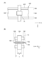
- FIG. 2A is a plan view schematically showing how the transport mechanism transports the electrode plate.
- FIG. 2B is a cross-sectional view schematically showing how the transport mechanism transports the electrode plate. It is a figure which shows the relationship between the dimensional ratio a / b and the tension applied to an electrode plate. It is a schematic diagram of the uncoated portion stretching roll which a stretching mechanism has. It is a figure which shows the relationship between the presence / absence of the 1st tension reduction mechanism and the 2nd tension reduction mechanism, and the elongation rate of a coating part.
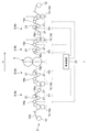
- FIG. 1 is a side view schematically showing the electrode plate manufacturing apparatus according to the embodiment.
- FIG. 2A is a plan view schematically showing how the transport mechanism transports the electrode plate.
- FIG. 2B is a cross-sectional view schematically showing how the transport mechanism transports the electrode plate.
- the electrode plate manufacturing apparatus 1 includes a transport line 2, a compression roll 4, a tension reducing mechanism 6, and a stretching mechanism 8.
- the tension reducing mechanism 6 and the stretching mechanism 8 are provided on both the upstream side and the downstream side of the compression roll 4 in the transport line 2.
- the tension reducing mechanism 6 on the upstream side will be referred to as a first tension reducing mechanism 6a
- the tension reducing mechanism 6 on the downstream side will be referred to as a second tension reducing mechanism 6b.
- the tension reducing mechanism 6a When it is not necessary to distinguish between the first tension reducing mechanism 6a and the second tension reducing mechanism 6b, these are collectively referred to as the tension reducing mechanism 6.
- the stretching mechanism 8 on the upstream side is referred to as the first stretching mechanism 8a
- the stretching mechanism 8 on the downstream side is referred to as the second stretching mechanism 8b
- the stretching mechanism 8 when it is not necessary to distinguish between the two, they are collectively referred to as the stretching mechanism 8.
- the transport line 2 is a mechanism for transporting the electrode plate 100.
- the electrode plate 100 has a coated portion 104 in which the electrode active material is coated on the surface of the long base material 102, and an uncoated portion 106 in which the electrode active material is not coated on the surface of the base material 102.
- the base material 102 functions as a current collector.
- the base material 102 is made of a foil or a porous body made of, for example, copper or aluminum.
- the base material 102 is made of a foil or a porous body made of, for example, stainless steel or aluminum.
- the electrode active material is graphite or the like when the electrode plate 100 is a negative electrode plate of a lithium ion secondary battery.
- the electrode active material is lithium cobalt oxide, lithium iron phosphate, or the like.
- the electrode active material is applied to the base material 102 in the form of an electrode mixture slurry in which, for example, a conductive auxiliary agent, a binder, a dispersant and the like are mixed.
- the electrode active material layer 108 is formed by drying and rolling the coating film after applying the electrode mixture slurry.
- the electrode active material layers 108 are provided on both sides of the base material 102.
- the coating portion 104 has a structure in which the base material 102 and the electrode active material layer 108 are laminated.
- the uncoated portion 106 is composed of only the base material 102.
- the transport line 2 includes a winding device 10, a winding device 12, and a transport mechanism 14.
- the unwinding device 10 is arranged at the starting point of the transport line 2.
- the unwinding device 10 holds the electrode plate 100 of the coating portion 104 that has not been compressed, for example, in a wound state, and sends the electrode plate 100 to the downstream side of the transport line 2.
- the take-up device 12 is arranged at the end point of the transfer line 2.
- the winding device 12 collects the electrode plate 100 that has been subjected to the compression treatment of the coating portion 104, for example, in the state of a wound body.
- the transport mechanism 14 is arranged between the unwinding device 10 and the winding device 12 on the transport line 2, and transports the electrode plate 100 from the unwinding device 10 toward the winding device 12.
- the transport mechanism 14 of the present embodiment includes a first transport mechanism 14a, a second transport mechanism 14b, a third transport mechanism 14c, and a fourth transport mechanism 14d.
- the first transport mechanism 14a to the fourth transport mechanism 14d are arranged at predetermined intervals in this order from the upstream side in the transport direction A of the electrode plate 100.
- a transport mechanism 14 when it is not necessary to distinguish between the first transport mechanism 14a and the fourth transport mechanism 14d, these are collectively referred to as a transport mechanism 14.
- the number of transport mechanisms 14 is not limited to four.
- the transport mechanism 14 of the present embodiment is composed of a nip roll that grips and transports the electrode plate 100.
- the transport mechanism 14 grips the coating portion 104 and transports the electrode plate 100. Therefore, the transport mechanism 14 does not come into contact with the uncoated portion 106. As a result, it is possible to prevent wrinkles from being generated in the uncoated portion 106 when the electrode plate 100 in which the uncoated portion 106 is stretched more than the coated portion 104 is conveyed by the stretching mechanism 8 described later. Therefore, the structure in which the transport mechanism 14 grips only the coating portion 104 is particularly preferable to be adopted in the second transport mechanism 14b that determines the downstream end of the first stretching mechanism 8a.
- the dimension of the portion of the coating portion 104 gripped by the transport mechanism 14 in the width direction B is defined as a, and the dimension of the coating portion 104 in the width direction B is defined as b. It is designed to satisfy a / b ⁇ 0.4.
- the width direction B is a direction orthogonal to the transport direction A of the electrode plate 100.
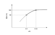
- FIG. 3 is a diagram showing the relationship between the dimensional ratio a / b and the tension applied to the electrode plate 100.
- the “tension” on the vertical axis is the ratio of the tension obtained at each a / b to the tension obtained when the transport mechanism 14 grips the entire width of the coating portion 104 (that is, a / b is 1).
- a / b is 0.53 or more.
- the transport mechanism 14 may be configured to suck and transport the electrode plate 100.
- the transport mechanism 14 is composed of a suction roll or the like.
- the dimension a is the dimension in the width direction B of the portion attracted by the transport mechanism 14 in the coating portion 104.
- the transport mechanism 14 may have a plurality of nip rolls or suction rolls arranged in the width direction B. In this case, the total dimension of the portion gripped or sucked by each roll is the dimension a.
- a compression roll 4 is provided between the second transport mechanism 14b and the third transport mechanism 14c in the transport line 2.
- the compression roll 4 is composed of a pair of rolls arranged at predetermined intervals. By passing the electrode plate 100 between the pair of rolls, the coating portion 104 can be pressurized in the thickness direction of the electrode plate 100. As a result, the coating portion 104 is compressed.
- the electrode plate 100 is also conveyed by the rotation of the compression roll 4. Therefore, the compression roll 4 also functions as a nip roll.
- a tension adjusting unit is provided in the section between each nip roll (that is, each transport mechanism 14 and the compression roll 4), and the tension applied to the electrode plate 100 being transported on the transport line 2 is independently adjusted in each section. ..
- the tension adjusting unit of the present embodiment is composed of a dancer roll.
- first tension adjusting unit 16a is provided in the first section R1 between the first transport mechanism 14a and the second transport mechanism 14b.
- a second tension adjusting portion 16b is provided in the second section R2 between the second transport mechanism 14b and the compression roll 4.
- a third tension adjusting portion 16c is provided in the third section R3 between the compression roll 4 and the third transport mechanism 14c.
- a fourth tension adjusting unit 16d is provided in the fourth section R4 between the third transport mechanism 14c and the fourth transport mechanism 14d.
- the first section R1 is provided with a first tension measuring device 18a for measuring the tension applied to the electrode plate 100 by the first tension adjusting unit 16a.
- the second section R2 is provided with a second tension measuring device 18b that measures the tension applied to the electrode plate 100 by the second tension adjusting unit 16b.
- the third section R3 is provided with a third tension measuring device 18c that measures the tension applied to the electrode plate 100 by the third tension adjusting unit 16c.
- a fourth tension measuring device 18d for measuring the tension applied to the electrode plate 100 by the fourth tension adjusting unit 16d is provided. Examples of the first tension measuring device 18a to the fourth tension measuring device 18d include known contact type tension meters and tension pickup rolls.
- the operations of the compression roll 4, the transport mechanism 14, the first tension adjusting unit 16a to the fourth tension adjusting unit 16d, and the like are controlled by the control device 20.
- the control device 20 is realized by elements and circuits such as a computer CPU and memory as a hardware configuration, and is realized by a computer program or the like as a software configuration, but in FIG. 1, it is realized by their cooperation. It is drawn as a functional block. It is well understood by those skilled in the art that this functional block can be realized in various ways by a combination of hardware and software.
- the control device 20 receives tension data from the first tension measuring device 18a to the fourth tension measuring device 18d, and controls the drive of the first tension adjusting unit 16a to the fourth tension adjusting unit 16d based on the received tension data. .. Thereby, the tension applied to the electrode plate 100 in the first section R1 to the fourth section R4 can be adjusted to a desired value.
- the control device 20 can also control the operation of each part based on a preset fixed operation program, instead of feedback control based on the measurement results of the first tension measuring device 18a to the fourth tension measuring device 18d. ..
- a first tension reducing mechanism 6a is provided on the upstream side of the compression roll 4 in the transport line 2.
- the first tension reducing mechanism 6a is arranged in the second section R2 to reduce the tension applied to the electrode plate 100 in the second section R2. That is, the first tension reducing mechanism 6a is arranged in the upstream section of the transport line 2 ending with the compression roll 4.
- the first tension reducing mechanism 6a includes a second tension adjusting unit 16b, a second tension measuring device 18b, a guide roll 21, a control device 20, and the like.
- the tension applied to the electrode plate 100 in the second section R2 is applied to the electrode plate 100 in the first section R1. It is reduced below such tension. For example, the tension applied to the electrode plate 100 in the second section R2 is adjusted to 0.
- a second tension reducing mechanism 6b is provided on the downstream side of the compression roll 4.
- the second tension reducing mechanism 6b is arranged in the third section R3 to reduce the tension applied to the electrode plate 100 in the third section R3. That is, the second tension reducing mechanism 6b is arranged in the downstream section starting from the compression roll 4.
- the second tension reducing mechanism 6b includes a third tension adjusting unit 16c, a third tension measuring device 18c, a guide roll 21, a control device 20, and the like.
- the tension applied to the electrode plate 100 in the third section R3 is applied to the electrode plate 100 in the fourth section R4. It is reduced below such tension. For example, the tension applied to the electrode plate 100 in the third section R3 is adjusted to 0.
- the stretching mechanism 8 is provided at a position farther from the compression roll 4 than the tension reducing mechanism 6 in the transport line 2 to stretch the uncoated portion 106.
- the first stretching mechanism 8a is provided in the first section R1 on the upstream side of the first tension reducing mechanism 6a
- the second stretching is provided in the fourth section R4 on the downstream side of the second tension reducing mechanism 6b.
- a mechanism 8b is provided.
- the first stretching mechanism 8a includes a first tension adjusting unit 16a, a first tension measuring device 18a, a guide roll 21, a control device 20, and the like.
- the second stretching mechanism 8b includes a fourth tension adjusting unit 16d, a fourth tension measuring device 18d, a guide roll 21, a control device 20, and the like.
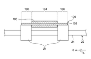
- the stretching mechanism 8 has an uncoated portion stretching roll 22 shown in FIG. FIG. 4 is a schematic view of the uncoated portion stretching roll 22 included in the stretching mechanism 8.
- the uncoated portion stretching roll 22 has a rotating shaft 24 and a supporting portion 26.
- the rotating shaft 24 rotates as the electrode plate 100 is conveyed.
- the support portion 26 is provided on the outer periphery of the rotary shaft 24 and rotates together with the rotary shaft 24 while supporting the electrode plate 100.
- the support portion 26 has a step and comes into contact with only the uncoated portion 106 of the electrode plate 100.
- the coated portion 104 is separated from the uncoated portion stretching roll 22.
- the uncoated portion 106 When tension is applied to the electrode plate 100 by the first tension adjusting portion 16a or the fourth tension adjusting portion 16d in this state, the uncoated portion 106 is pressed by the support portion 26 and stretched. On the other hand, since the coated portion 104 is not pressed by the support portion 26, the stretching amount is smaller than that of the uncoated portion 106.
- the dancer roll or the guide roll 21 constituting the first tension adjusting portion 16a is composed of the uncoated portion stretching roll 22.
- the dancer roll or the guide roll 21 constituting the fourth tension adjusting portion 16d is composed of the uncoated portion stretching roll 22.
- the guide roll 21 (roll with the load cell) on which the first tension measuring device 18a or the fourth tension measuring device 18d is installed is used as the uncoated portion stretching roll 22. It is preferable not to do so.
- the present inventor when the coating portion 104 is compressed by the compression roll 4 while the electrode plate 100 is under tension, the base material 102 constituting the coating portion 104 is excessively stretched and broken. I found that there are cases.
- the amount of the electrode mixture slurry applied has increased, and the thickness of the electrode active material layer 108 has tended to increase.
- the thickness of the electrode active material layer 108 increases, a larger force is applied to the base material 102 when the coating portion 104 is compressed by the compression roll 4, and the base material 102 is further stretched.
- the tension reducing mechanism 6 is provided on both the upstream side and the downstream side of the compression roll 4, but the tension reduction mechanism 6 is not limited to this and may be provided on at least one of the upstream side and the downstream side of the compression roll 4. For example, it is possible to suppress the stretching of the base material 102 as compared with the case where none of them is provided.
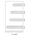
- FIG. 5 is a diagram showing the relationship between the presence / absence of the first tension reducing mechanism 6a and the second tension reducing mechanism 6b and the elongation rate of the coating portion 104.
- a reference example is a manufacturing apparatus provided with neither a first tension reducing mechanism 6a nor a second tension reducing mechanism 6b.
- the first embodiment is a manufacturing apparatus including only the second tension reducing mechanism 6b. That is, it is an example in which the tension caused by the first stretching mechanism 8a is transmitted to the electrode plate 100 from the upstream side of the compression roll 4.
- the second embodiment is a manufacturing apparatus including only the first tension reducing mechanism 6a. That is, it is an example in which the tension caused by the second stretching mechanism 8b is transmitted to the electrode plate 100 from the downstream side of the compression roll 4.
- Example 3 is a manufacturing apparatus including a first tension reducing mechanism 6a and a second tension reducing mechanism 6b. That is, it is an embodiment in which the tension caused by the stretching mechanism 8 is not transmitted to the electrode plate 100 from both the upstream side and the downstream side of the compression roll 4. Further, the manufacturing apparatus of the reference example and each embodiment includes a first stretching mechanism 8a and a second stretching mechanism 8b.
- the "elongation rate of the coated portion" on the vertical axis is the ratio of the length of the coated portion 104 compressed by each manufacturing apparatus to the length of the uncompressed coated portion 104. The elongation rate of the coated portion 104 was obtained by marking lines on the coated portion 104 and the uncoated portion 106 and measuring the length between the lines before and after compression with a metal scale or a magnifying microscope.
- the elongation rate of the coating portion 104 was reduced as compared with the manufacturing apparatus of the reference example. From this, it was confirmed that if the tension reducing mechanism 6 is provided on at least one of the upstream side and the downstream side of the compression roll 4, the stretching of the coating portion 104 can be suppressed, and thus the breakage of the electrode plate 100 can be suppressed. .. Further, from the results of Examples 1 and 2, when the tension reducing mechanism 6 is provided only on either the upstream side or the downstream side of the compression roll 4, it is better to provide the tension reducing mechanism 6 on the upstream side. It was confirmed that the breakage of the plate 100 can be further suppressed.
- Example 3 when the tension reducing mechanism 6 is provided on both the upstream side and the downstream side of the compression roll 4, the elongation of the coating portion 104 can be suppressed most, and thus the breakage of the electrode plate 100 can be suppressed most. It was confirmed that it could be done. Even when the stretching mechanism 8 is not provided on the transport line 2, tension is not a little applied to the electrode plate 100 when the electrode plate 100 is transported. Therefore, even when the stretching mechanism 8 is not provided, the effect of suppressing the breakage of the electrode plate 100 by the tension reducing mechanism 6 can be obtained.
- the manufacturing apparatus 1 for the electrode plate 100 is provided on the transport line 2 for transporting the electrode plate 100 having the coated portion 104 and the uncoated portion 106, and the transport line 2 for coating.
- a tension reduction section at least one of a section extending upstream from the compression roll 4 and a section extending downstream from the compression roll 4, the base material 102 is stretched when the coating portion 104 is compressed by the compression roll 4. Can be suppressed. As a result, the risk of the electrode plate breaking can be reduced, and the electrode plate 100 can be manufactured more stably.
- the tension reducing mechanism 6 of the present embodiment is provided in both the upstream side section and the downstream side section of the compression roll 4. Thereby, the stretching of the base material 102 can be further suppressed. Therefore, the electrode plate 100 can be manufactured more stably.
- the manufacturing apparatus 1 of the present embodiment includes a stretching mechanism 8 that stretches the uncoated portion 106 at a position farther from the compression roll 4 than the tension reducing mechanism 6 in the transport line 2.
- a stretching mechanism 8 that stretches the uncoated portion 106 at a position farther from the compression roll 4 than the tension reducing mechanism 6 in the transport line 2.
- the stretching mechanism 8 of the present embodiment is provided on both the upstream side and the downstream side of the compression roll 4.
- the uncoated portion 106 can be stretched in two steps.
- the transport line 2 of the present embodiment has a transport mechanism 14 that grips or attracts the coating portion 104 to transport the electrode plate 100. As a result, it is possible to suppress the occurrence of wrinkles in the uncoated portion 106, and the electrode plate 100 can be manufactured more stably.
- the dimension of the width direction B orthogonal to the transport direction A of the electrode plate 100 of the portion gripped or attracted by the transport mechanism 14 in the coating portion 104 is a, and the dimension of the coating portion 104 is set to a.
- the dimension of the width direction B is b, a / b ⁇ 0.4 is satisfied. As a result, it is possible to suppress a decrease in the transport speed of the electrode plate 100 while suppressing the occurrence of wrinkles in the uncoated portion 106.
- the present disclosure can be used for an electrode plate manufacturing apparatus and an electrode plate manufacturing method.
Landscapes
- Engineering & Computer Science (AREA)
- Chemical & Material Sciences (AREA)
- Manufacturing & Machinery (AREA)
- Chemical Kinetics & Catalysis (AREA)
- Electrochemistry (AREA)
- General Chemical & Material Sciences (AREA)
- Materials Engineering (AREA)
- Mechanical Engineering (AREA)
- Battery Electrode And Active Subsutance (AREA)
- Controlling Rewinding, Feeding, Winding, Or Abnormalities Of Webs (AREA)
- Press Drives And Press Lines (AREA)
Abstract
Dispositif 1 pour fabriquer une plaque d'électrode 100 comprenant : une ligne de transport 2 pour la plaque d'électrode 100 présentant une section revêtue où une surface d'un substrat a été revêtue d'une substance active d'électrode et une section non revêtue où la surface du substrat n'a pas été revêtue de la substance active d'électrode ; un rouleau de compression 4 qui est disposé sur la ligne de transport 2 et comprime la section revêtue ; et un mécanisme de réduction de tension 6 qui réduit la tension appliquée à la plaque d'électrode 100, et qui est disposé sur un segment côté amont ayant, en tant qu'extrémité terminale, le rouleau de compression 4 dans la ligne de transport 2 et/ou un segment latéral aval ayant, en tant qu'extrémité de départ, le rouleau de compression 4.
Priority Applications (2)
| Application Number | Priority Date | Filing Date | Title |
|---|---|---|---|
| CN202180022478.2A CN115315828A (zh) | 2020-03-30 | 2021-03-25 | 电极板的制造装置以及电极板的制造方法 |
| US17/915,777 US12334541B2 (en) | 2020-03-30 | 2021-03-25 | Device for manufacturing electrode plate and method for manufacturing electrode plate |
Applications Claiming Priority (2)
| Application Number | Priority Date | Filing Date | Title |
|---|---|---|---|
| JP2020-059675 | 2020-03-30 | ||
| JP2020059675A JP7165156B2 (ja) | 2020-03-30 | 2020-03-30 | 電極板の製造装置および電極板の製造方法 |
Publications (1)
| Publication Number | Publication Date |
|---|---|
| WO2021200546A1 true WO2021200546A1 (fr) | 2021-10-07 |
Family
ID=77919478
Family Applications (1)
| Application Number | Title | Priority Date | Filing Date |
|---|---|---|---|
| PCT/JP2021/012559 Ceased WO2021200546A1 (fr) | 2020-03-30 | 2021-03-25 | Dispositif de fabrication de plaque d'électrode et procédé de fabrication de plaque d'électrode |
Country Status (4)
| Country | Link |
|---|---|
| US (1) | US12334541B2 (fr) |
| JP (1) | JP7165156B2 (fr) |
| CN (1) | CN115315828A (fr) |
| WO (1) | WO2021200546A1 (fr) |
Cited By (2)
| Publication number | Priority date | Publication date | Assignee | Title |
|---|---|---|---|---|
| EP4257526A4 (fr) * | 2022-02-28 | 2024-12-25 | Contemporary Amperex Technology (Hong Kong) Limited | Mécanisme de changement de direction de bande de matériau, appareil de séchage et dispositif de fabrication de plaque d'électrode |
| CN120003081A (zh) * | 2025-04-21 | 2025-05-16 | 宁德时代新能源科技股份有限公司 | 极片辊压装置、极片辊压方法和极片生产系统 |
Families Citing this family (2)
| Publication number | Priority date | Publication date | Assignee | Title |
|---|---|---|---|---|
| KR102840394B1 (ko) * | 2020-04-14 | 2025-07-29 | 주식회사 엘지에너지솔루션 | 권취롤로부터 전극 기재를 이송하는 시스템 및 방법 |
| JP2024040919A (ja) * | 2022-09-13 | 2024-03-26 | 株式会社東芝 | 電極構造体の製造方法及び製造装置 |
Citations (5)
| Publication number | Priority date | Publication date | Assignee | Title |
|---|---|---|---|---|
| JP2014072114A (ja) * | 2012-10-01 | 2014-04-21 | Hitachi Power Solutions Co Ltd | 電極材料用ロールプレス設備及び電極シートの製造方法 |
| JP2014220113A (ja) * | 2013-05-08 | 2014-11-20 | 株式会社日立パワーソリューションズ | 電極材料のロールプレス方法及びロールプレス設備 |
| JP2015069747A (ja) * | 2013-09-27 | 2015-04-13 | 株式会社日立パワーソリューションズ | 電極材料用スリッター設備および電極材製造設備 |
| JP2016120503A (ja) * | 2014-12-24 | 2016-07-07 | 株式会社日立パワーソリューションズ | 加圧ロール及びそれを用いたロールプレス機 |
| JP2018063860A (ja) * | 2016-10-13 | 2018-04-19 | 株式会社豊田自動織機 | ロールプレス方法 |
Family Cites Families (7)
| Publication number | Priority date | Publication date | Assignee | Title |
|---|---|---|---|---|
| JP2002184394A (ja) | 2000-12-12 | 2002-06-28 | Matsushita Electric Ind Co Ltd | シート材の圧延方法 |
| JP2005093236A (ja) | 2003-09-17 | 2005-04-07 | Toyota Motor Corp | シート電極の製造方法 |
| JP5757414B2 (ja) * | 2010-08-18 | 2015-07-29 | 株式会社Gsユアサ | 電池用電極シート及びその製造方法 |
| JP2017228349A (ja) | 2016-06-20 | 2017-12-28 | トヨタ自動車株式会社 | 二次電池の製造方法 |
| JP2018063660A (ja) | 2016-10-14 | 2018-04-19 | トヨタ自動車株式会社 | 買い物支援装置および買い物支援方法 |
| JP2020035537A (ja) * | 2018-08-27 | 2020-03-05 | 株式会社豊田自動織機 | 電極シートの製造装置 |
| CN113439352A (zh) * | 2019-02-19 | 2021-09-24 | 三洋电机株式会社 | 非水电解质二次电池、及其中使用的正极板的制造方法 |
-
2020
- 2020-03-30 JP JP2020059675A patent/JP7165156B2/ja active Active
-
2021
- 2021-03-25 US US17/915,777 patent/US12334541B2/en active Active
- 2021-03-25 CN CN202180022478.2A patent/CN115315828A/zh active Pending
- 2021-03-25 WO PCT/JP2021/012559 patent/WO2021200546A1/fr not_active Ceased
Patent Citations (5)
| Publication number | Priority date | Publication date | Assignee | Title |
|---|---|---|---|---|
| JP2014072114A (ja) * | 2012-10-01 | 2014-04-21 | Hitachi Power Solutions Co Ltd | 電極材料用ロールプレス設備及び電極シートの製造方法 |
| JP2014220113A (ja) * | 2013-05-08 | 2014-11-20 | 株式会社日立パワーソリューションズ | 電極材料のロールプレス方法及びロールプレス設備 |
| JP2015069747A (ja) * | 2013-09-27 | 2015-04-13 | 株式会社日立パワーソリューションズ | 電極材料用スリッター設備および電極材製造設備 |
| JP2016120503A (ja) * | 2014-12-24 | 2016-07-07 | 株式会社日立パワーソリューションズ | 加圧ロール及びそれを用いたロールプレス機 |
| JP2018063860A (ja) * | 2016-10-13 | 2018-04-19 | 株式会社豊田自動織機 | ロールプレス方法 |
Cited By (2)
| Publication number | Priority date | Publication date | Assignee | Title |
|---|---|---|---|---|
| EP4257526A4 (fr) * | 2022-02-28 | 2024-12-25 | Contemporary Amperex Technology (Hong Kong) Limited | Mécanisme de changement de direction de bande de matériau, appareil de séchage et dispositif de fabrication de plaque d'électrode |
| CN120003081A (zh) * | 2025-04-21 | 2025-05-16 | 宁德时代新能源科技股份有限公司 | 极片辊压装置、极片辊压方法和极片生产系统 |
Also Published As
| Publication number | Publication date |
|---|---|
| US12334541B2 (en) | 2025-06-17 |
| JP2021155207A (ja) | 2021-10-07 |
| US20230223513A1 (en) | 2023-07-13 |
| CN115315828A (zh) | 2022-11-08 |
| JP7165156B2 (ja) | 2022-11-02 |
Similar Documents
| Publication | Publication Date | Title |
|---|---|---|
| WO2021200546A1 (fr) | Dispositif de fabrication de plaque d'électrode et procédé de fabrication de plaque d'électrode | |
| US8637189B2 (en) | Battery electrode sheet and manufacturing method therefor | |
| JP5228133B1 (ja) | 電極材料用ロールプレス設備及び電極シートの製造方法 | |
| US20100330267A1 (en) | Method for producing electrode plate for battery | |
| CN113439352A (zh) | 非水电解质二次电池、及其中使用的正极板的制造方法 | |
| JP2024068766A (ja) | 蓄電素子の製造装置および蓄電素子の製造方法 | |
| JP2014102991A (ja) | 電極の製造方法および電極の製造装置 | |
| JP2014107166A (ja) | 電極の製造装置および電極の製造方法 | |
| CN118299500A (zh) | 用于制造电极的装置和方法 | |
| KR20180022039A (ko) | 가이드 롤러를 포함하는 전극시트 압연 장치 | |
| JP2014101221A (ja) | 帯状体の搬送装置 | |
| WO2024070092A1 (fr) | Dispositif de fabrication pour feuille de mélange | |
| JP7187422B2 (ja) | 電極シート製造装置及び電極シート製造方法 | |
| CN110311088A (zh) | 电极板的制造方法及制造装置 | |
| JP6973241B2 (ja) | 膜電極ガス拡散層接合体の連続製造方法 | |
| CN222320277U (zh) | 干电极制备装置 | |
| US20250054940A1 (en) | Rolling apparatus and rolling method for electrode sheet | |
| CN223405228U (zh) | 一种压辊装置及干法涂布设备 | |
| CN114388728B (zh) | 电极片的制造方法 | |
| WO2023139860A1 (fr) | Dispositif d'étirement et de transport pour comprimé cru | |
| CN220821621U (zh) | 电极制备装置 | |
| JP2025179749A (ja) | 電極シート製造装置、電極シートの製造方法および電池の製造方法 | |
| CN115020629B (zh) | 辊压装置以及压实完毕带状电极板的制造方法 | |
| JP2025179750A (ja) | 電極シート製造装置および電極シートの製造方法 | |
| KR20260018613A (ko) | 전극용 압연 롤 및 이를 포함하는 압연 장치 |
Legal Events
| Date | Code | Title | Description |
|---|---|---|---|
| 121 | Ep: the epo has been informed by wipo that ep was designated in this application |
Ref document number: 21781726 Country of ref document: EP Kind code of ref document: A1 |
|
| NENP | Non-entry into the national phase |
Ref country code: DE |
|
| 122 | Ep: pct application non-entry in european phase |
Ref document number: 21781726 Country of ref document: EP Kind code of ref document: A1 |
|
| WWG | Wipo information: grant in national office |
Ref document number: 17915777 Country of ref document: US |