WO2021201011A1 - 水加熱システム - Google Patents
水加熱システム Download PDFInfo
- Publication number
- WO2021201011A1 WO2021201011A1 PCT/JP2021/013653 JP2021013653W WO2021201011A1 WO 2021201011 A1 WO2021201011 A1 WO 2021201011A1 JP 2021013653 W JP2021013653 W JP 2021013653W WO 2021201011 A1 WO2021201011 A1 WO 2021201011A1
- Authority
- WO
- WIPO (PCT)
- Prior art keywords
- water
- refrigerant
- heat
- circuit
- heat exchange
- Prior art date
- Legal status (The legal status is an assumption and is not a legal conclusion. Google has not performed a legal analysis and makes no representation as to the accuracy of the status listed.)
- Ceased
Links
Images





Classifications
-
- F—MECHANICAL ENGINEERING; LIGHTING; HEATING; WEAPONS; BLASTING
- F24—HEATING; RANGES; VENTILATING
- F24H—FLUID HEATERS, e.g. WATER OR AIR HEATERS, HAVING HEAT-GENERATING MEANS, e.g. HEAT PUMPS, IN GENERAL
- F24H4/00—Fluid heaters characterised by the use of heat pumps
- F24H4/02—Water heaters
- F24H4/04—Storage heaters
-
- F—MECHANICAL ENGINEERING; LIGHTING; HEATING; WEAPONS; BLASTING
- F24—HEATING; RANGES; VENTILATING
- F24H—FLUID HEATERS, e.g. WATER OR AIR HEATERS, HAVING HEAT-GENERATING MEANS, e.g. HEAT PUMPS, IN GENERAL
- F24H4/00—Fluid heaters characterised by the use of heat pumps
- F24H4/02—Water heaters
-
- F—MECHANICAL ENGINEERING; LIGHTING; HEATING; WEAPONS; BLASTING
- F24—HEATING; RANGES; VENTILATING
- F24D—DOMESTIC- OR SPACE-HEATING SYSTEMS, e.g. CENTRAL HEATING SYSTEMS; DOMESTIC HOT-WATER SUPPLY SYSTEMS; ELEMENTS OR COMPONENTS THEREFOR
- F24D17/00—Domestic hot-water supply systems
- F24D17/02—Domestic hot-water supply systems using heat pumps
-
- F—MECHANICAL ENGINEERING; LIGHTING; HEATING; WEAPONS; BLASTING
- F24—HEATING; RANGES; VENTILATING
- F24D—DOMESTIC- OR SPACE-HEATING SYSTEMS, e.g. CENTRAL HEATING SYSTEMS; DOMESTIC HOT-WATER SUPPLY SYSTEMS; ELEMENTS OR COMPONENTS THEREFOR
- F24D19/00—Details
- F24D19/0092—Devices for preventing or removing corrosion, slime or scale
-
- F—MECHANICAL ENGINEERING; LIGHTING; HEATING; WEAPONS; BLASTING
- F25—REFRIGERATION OR COOLING; COMBINED HEATING AND REFRIGERATION SYSTEMS; HEAT PUMP SYSTEMS; MANUFACTURE OR STORAGE OF ICE; LIQUEFACTION SOLIDIFICATION OF GASES
- F25B—REFRIGERATION MACHINES, PLANTS OR SYSTEMS; COMBINED HEATING AND REFRIGERATION SYSTEMS; HEAT PUMP SYSTEMS
- F25B13/00—Compression machines, plants or systems, with reversible cycle
-
- F—MECHANICAL ENGINEERING; LIGHTING; HEATING; WEAPONS; BLASTING
- F25—REFRIGERATION OR COOLING; COMBINED HEATING AND REFRIGERATION SYSTEMS; HEAT PUMP SYSTEMS; MANUFACTURE OR STORAGE OF ICE; LIQUEFACTION SOLIDIFICATION OF GASES
- F25B—REFRIGERATION MACHINES, PLANTS OR SYSTEMS; COMBINED HEATING AND REFRIGERATION SYSTEMS; HEAT PUMP SYSTEMS
- F25B41/00—Fluid-circulation arrangements
- F25B41/20—Disposition of valves, e.g. of on-off valves or flow control valves
-
- F—MECHANICAL ENGINEERING; LIGHTING; HEATING; WEAPONS; BLASTING
- F25—REFRIGERATION OR COOLING; COMBINED HEATING AND REFRIGERATION SYSTEMS; HEAT PUMP SYSTEMS; MANUFACTURE OR STORAGE OF ICE; LIQUEFACTION SOLIDIFICATION OF GASES
- F25B—REFRIGERATION MACHINES, PLANTS OR SYSTEMS; COMBINED HEATING AND REFRIGERATION SYSTEMS; HEAT PUMP SYSTEMS
- F25B41/00—Fluid-circulation arrangements
- F25B41/40—Fluid line arrangements
-
- F—MECHANICAL ENGINEERING; LIGHTING; HEATING; WEAPONS; BLASTING
- F25—REFRIGERATION OR COOLING; COMBINED HEATING AND REFRIGERATION SYSTEMS; HEAT PUMP SYSTEMS; MANUFACTURE OR STORAGE OF ICE; LIQUEFACTION SOLIDIFICATION OF GASES
- F25B—REFRIGERATION MACHINES, PLANTS OR SYSTEMS; COMBINED HEATING AND REFRIGERATION SYSTEMS; HEAT PUMP SYSTEMS
- F25B6/00—Compression machines, plants or systems, with several condenser circuits
- F25B6/04—Compression machines, plants or systems, with several condenser circuits arranged in series
-
- F—MECHANICAL ENGINEERING; LIGHTING; HEATING; WEAPONS; BLASTING
- F24—HEATING; RANGES; VENTILATING
- F24D—DOMESTIC- OR SPACE-HEATING SYSTEMS, e.g. CENTRAL HEATING SYSTEMS; DOMESTIC HOT-WATER SUPPLY SYSTEMS; ELEMENTS OR COMPONENTS THEREFOR
- F24D2220/00—Components of central heating installations excluding heat sources
- F24D2220/08—Storage tanks
-
- F—MECHANICAL ENGINEERING; LIGHTING; HEATING; WEAPONS; BLASTING
- F25—REFRIGERATION OR COOLING; COMBINED HEATING AND REFRIGERATION SYSTEMS; HEAT PUMP SYSTEMS; MANUFACTURE OR STORAGE OF ICE; LIQUEFACTION SOLIDIFICATION OF GASES
- F25B—REFRIGERATION MACHINES, PLANTS OR SYSTEMS; COMBINED HEATING AND REFRIGERATION SYSTEMS; HEAT PUMP SYSTEMS
- F25B2313/00—Compression machines, plants or systems with reversible cycle not otherwise provided for
- F25B2313/003—Indoor unit with water as a heat sink or heat source
-
- F—MECHANICAL ENGINEERING; LIGHTING; HEATING; WEAPONS; BLASTING
- F25—REFRIGERATION OR COOLING; COMBINED HEATING AND REFRIGERATION SYSTEMS; HEAT PUMP SYSTEMS; MANUFACTURE OR STORAGE OF ICE; LIQUEFACTION SOLIDIFICATION OF GASES
- F25B—REFRIGERATION MACHINES, PLANTS OR SYSTEMS; COMBINED HEATING AND REFRIGERATION SYSTEMS; HEAT PUMP SYSTEMS
- F25B2313/00—Compression machines, plants or systems with reversible cycle not otherwise provided for
- F25B2313/023—Compression machines, plants or systems with reversible cycle not otherwise provided for using multiple indoor units
- F25B2313/0232—Compression machines, plants or systems with reversible cycle not otherwise provided for using multiple indoor units with bypasses
- F25B2313/02322—Compression machines, plants or systems with reversible cycle not otherwise provided for using multiple indoor units with bypasses during defrosting
-
- F—MECHANICAL ENGINEERING; LIGHTING; HEATING; WEAPONS; BLASTING
- F25—REFRIGERATION OR COOLING; COMBINED HEATING AND REFRIGERATION SYSTEMS; HEAT PUMP SYSTEMS; MANUFACTURE OR STORAGE OF ICE; LIQUEFACTION SOLIDIFICATION OF GASES
- F25B—REFRIGERATION MACHINES, PLANTS OR SYSTEMS; COMBINED HEATING AND REFRIGERATION SYSTEMS; HEAT PUMP SYSTEMS
- F25B2313/00—Compression machines, plants or systems with reversible cycle not otherwise provided for
- F25B2313/023—Compression machines, plants or systems with reversible cycle not otherwise provided for using multiple indoor units
- F25B2313/0234—Compression machines, plants or systems with reversible cycle not otherwise provided for using multiple indoor units in series arrangements
- F25B2313/02344—Compression machines, plants or systems with reversible cycle not otherwise provided for using multiple indoor units in series arrangements during heating
-
- F—MECHANICAL ENGINEERING; LIGHTING; HEATING; WEAPONS; BLASTING
- F25—REFRIGERATION OR COOLING; COMBINED HEATING AND REFRIGERATION SYSTEMS; HEAT PUMP SYSTEMS; MANUFACTURE OR STORAGE OF ICE; LIQUEFACTION SOLIDIFICATION OF GASES
- F25B—REFRIGERATION MACHINES, PLANTS OR SYSTEMS; COMBINED HEATING AND REFRIGERATION SYSTEMS; HEAT PUMP SYSTEMS
- F25B2339/00—Details of evaporators; Details of condensers
- F25B2339/04—Details of condensers
- F25B2339/047—Water-cooled condensers
-
- F—MECHANICAL ENGINEERING; LIGHTING; HEATING; WEAPONS; BLASTING
- F25—REFRIGERATION OR COOLING; COMBINED HEATING AND REFRIGERATION SYSTEMS; HEAT PUMP SYSTEMS; MANUFACTURE OR STORAGE OF ICE; LIQUEFACTION SOLIDIFICATION OF GASES
- F25B—REFRIGERATION MACHINES, PLANTS OR SYSTEMS; COMBINED HEATING AND REFRIGERATION SYSTEMS; HEAT PUMP SYSTEMS
- F25B2400/00—Component parts or details not otherwise provided for in this subclass
- F25B2400/04—Refrigeration circuit bypassing means
- F25B2400/0403—Refrigeration circuit bypassing means for condensers
-
- F—MECHANICAL ENGINEERING; LIGHTING; HEATING; WEAPONS; BLASTING
- F25—REFRIGERATION OR COOLING; COMBINED HEATING AND REFRIGERATION SYSTEMS; HEAT PUMP SYSTEMS; MANUFACTURE OR STORAGE OF ICE; LIQUEFACTION SOLIDIFICATION OF GASES
- F25B—REFRIGERATION MACHINES, PLANTS OR SYSTEMS; COMBINED HEATING AND REFRIGERATION SYSTEMS; HEAT PUMP SYSTEMS
- F25B2600/00—Control issues
- F25B2600/25—Control of valves
- F25B2600/2501—Bypass valves
-
- F—MECHANICAL ENGINEERING; LIGHTING; HEATING; WEAPONS; BLASTING
- F25—REFRIGERATION OR COOLING; COMBINED HEATING AND REFRIGERATION SYSTEMS; HEAT PUMP SYSTEMS; MANUFACTURE OR STORAGE OF ICE; LIQUEFACTION SOLIDIFICATION OF GASES
- F25B—REFRIGERATION MACHINES, PLANTS OR SYSTEMS; COMBINED HEATING AND REFRIGERATION SYSTEMS; HEAT PUMP SYSTEMS
- F25B2600/00—Control issues
- F25B2600/25—Control of valves
- F25B2600/2519—On-off valves
-
- F—MECHANICAL ENGINEERING; LIGHTING; HEATING; WEAPONS; BLASTING
- F25—REFRIGERATION OR COOLING; COMBINED HEATING AND REFRIGERATION SYSTEMS; HEAT PUMP SYSTEMS; MANUFACTURE OR STORAGE OF ICE; LIQUEFACTION SOLIDIFICATION OF GASES
- F25B—REFRIGERATION MACHINES, PLANTS OR SYSTEMS; COMBINED HEATING AND REFRIGERATION SYSTEMS; HEAT PUMP SYSTEMS
- F25B47/00—Arrangements for preventing or removing deposits or corrosion, not provided for in another subclass
- F25B47/02—Defrosting cycles
- F25B47/022—Defrosting cycles hot gas defrosting
- F25B47/025—Defrosting cycles hot gas defrosting by reversing the cycle
-
- Y—GENERAL TAGGING OF NEW TECHNOLOGICAL DEVELOPMENTS; GENERAL TAGGING OF CROSS-SECTIONAL TECHNOLOGIES SPANNING OVER SEVERAL SECTIONS OF THE IPC; TECHNICAL SUBJECTS COVERED BY FORMER USPC CROSS-REFERENCE ART COLLECTIONS [XRACs] AND DIGESTS
- Y02—TECHNOLOGIES OR APPLICATIONS FOR MITIGATION OR ADAPTATION AGAINST CLIMATE CHANGE
- Y02B—CLIMATE CHANGE MITIGATION TECHNOLOGIES RELATED TO BUILDINGS, e.g. HOUSING, HOUSE APPLIANCES OR RELATED END-USER APPLICATIONS
- Y02B30/00—Energy efficient heating, ventilation or air conditioning [HVAC]
- Y02B30/12—Hot water central heating systems using heat pumps
Definitions
- a water heating system including a water heat exchanger that heats water with a refrigerant is known.
- scale may adhere due to the heating of water in the water heat exchanger.
- a heat pump hot water supply system disclosed in Patent Document 1 (Japanese Unexamined Patent Publication No. 2015-17761) can be mentioned.
- the water heat exchanger is divided into a high temperature side water heat exchanger and a low temperature side water heat exchanger, and a hot water outlet temperature sensor is provided on the hot water outlet side of the high temperature side water heat exchanger.
- a hot water temperature sensor is provided on the outlet side of the low temperature side water heat exchanger.
- Patent Document 1 the adhesion of the scale is stopped at the high temperature side water heat exchanger to prevent the spread to the low temperature side water heat exchanger.
- the scale is attached to the high temperature water side heat exchanger. In this case, the frequency of cleaning or replacing the high temperature water side heat exchanger becomes high, which is costly.
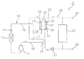
- the water heating system includes a refrigerant circuit and a water circuit.
- the refrigerant circuit has a compressor through which the refrigerant flows. Water flows through the water circuit.
- the refrigerant circuit and the water circuit share a water heat exchanger that heats water with the refrigerant discharged from the compressor.
- the water heat exchanger includes a first heat exchanger. In the first heat exchange section, the water at the water outlet section and the refrigerant exchange heat.
- the refrigerant circuit further has a heat radiating unit. The heat radiating section is arranged between the compressor and the first heat exchange section, and dissipates the heat of the refrigerant discharged from the compressor.
- the first heat exchange section where the water at the water outlet and the refrigerant exchange heat is the part where the water becomes hot in the water heat exchanger.
- a heat radiating unit that dissipates heat of the refrigerant is arranged between the compressor and the first heat exchange unit. Since the heat radiating section dissipates heat before the refrigerant flows into the first heat exchange section, the temperature of the refrigerant flowing into the first heat exchange section can be lowered. Therefore, in the first heat exchange section, it is possible to prevent the temperature of the water at the water outlet section from rising. Therefore, it is possible to prevent scale from adhering to the water heat exchanger.
- the water heating system according to the second aspect is the water heating system according to the first aspect, and the heat radiating unit includes a heat storage material that dissipates the heat of the refrigerant.
- the water heating system it is possible to suppress the scale from adhering to the water heat exchanger and to store the heat of the refrigerant in the heat storage material.
- the water heating system according to the third aspect is the water heating system of the first aspect or the second aspect, and includes a heat radiating device that dissipates the heat of the refrigerant to the atmosphere.
- the water heating system it is possible to suppress the scale from adhering to the water heat exchanger and dissipate the heat of the refrigerant to the atmosphere.
- the water heating system according to the fourth aspect is the water heating system from the first aspect to the third aspect, and is configured to dissipate the heat of the refrigerant to the water flowing upstream from the water outlet portion.
- the temperature of the water flowing upstream of the water outlet is lower than the temperature of the water flowing through the water outlet.
- the heat radiating section allows the low-temperature water on the upstream side to be heated by the refrigerant before being heated by the first heat exchange section. Therefore, it is possible to prevent scale from adhering to the water heat exchanger and to heat water efficiently.
- the water heating system according to the fifth aspect is the water heating system of the fourth aspect, and the water heat exchanger is a second heat exchange that exchanges heat with a refrigerant on the upstream side of the first heat exchange section in the water circuit. Includes more parts.
- the heat dissipation unit includes a second heat exchange unit.
- the temperature of the water flowing through the second heat exchange section is lower than the temperature of the water flowing through the first heat exchange section.
- the heat radiating unit can heat the low-temperature water in the second heat exchange unit with the refrigerant before the water is heated in the first heat exchange unit. Therefore, it is possible to realize a water heating system capable of suppressing the adhesion of scale to the water heat exchanger and efficiently heating water.
- the water heating system according to the sixth aspect is the water heating system according to the fifth aspect, and the refrigerant circuit has a bypass pipe in which the refrigerant bypasses one of the first heat exchange section and the second heat exchange section during the defrost operation. Have more.
- the amount of heat stored in the second heat exchange section having the high temperature refrigerant can be used by bypassing the first heat exchange section during the defrost operation, so that the defrost operation time can be shortened. can.
- the amount of heat stored by heat exchange with the high-temperature refrigerant can be used, so that the water can reach a predetermined temperature at an early stage during the heating operation.
- the water heating system according to the seventh aspect is the water heating system from the first aspect to the sixth aspect, and in at least a part of the water heat exchanger, the water flow direction and the refrigerant flow direction are opposite flows. There is a relationship of.
- the heat exchange efficiency can be improved by flowing the refrigerant and water in a countercurrent flow.
- the water heating system according to the eighth aspect is the water heating system from the first aspect to the seventh aspect, and at least one of the refrigerant circuit and the water circuit circulates the flow directions of the refrigerant and water in opposite directions. It is configured.
- the scale can be dispersed, so that the life of the water heat exchanger can be extended.
- the water heating system according to the ninth aspect is the water heating system from the first aspect to the eighth aspect, and the water circuit is an extraction unit that takes out water from between the water inlet portion and the water outlet portion of the water heat exchanger. Further has.
- high-temperature water at the water outlet portion heated by the refrigerant in the water heat exchanger and medium-temperature water between the water outlet portion and the water inlet portion can be taken out. ..
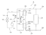
- the water heating system 1 heats water with a refrigerant.
- the water heating system 1 of the present embodiment is a hot water supply system.
- the water heating system 1 includes a refrigerant circuit 10 and a water circuit 20.
- the refrigerant circuit 10 and the water circuit 20 share a water heat exchanger 30 that heats water with a refrigerant.
- Refrigerant circuit Refrigerant flows in the refrigerant circuit 10.
- a fluid containing, for example, R32 is sealed in the refrigerant circuit 10 as a refrigerant.
- the refrigerant circuit 10 includes a compressor 11, a heat radiating unit 12, a condenser 13, an expansion valve 14, and an evaporator 15.
- the compressor 11, the heat radiating unit 12, the condenser 13, the expansion valve 14, and the evaporator 15 are sequentially connected by a refrigerant pipe.
- the compressor 11 is a device that compresses a low-pressure refrigerant until it reaches a high pressure.
- the compressor 11 of the present embodiment is a type of compressor whose rotation speed can be controlled by an inverter circuit to adjust the discharge amount of the refrigerant.
- the heat radiating unit 12 dissipates the heat of the refrigerant discharged from the compressor 11. Therefore, the temperature of the refrigerant that has passed through the heat radiating unit 12 drops.
- the heat radiating unit 12 is arranged between the first heat exchange unit 35 of the water heat exchanger 30, which will be described later, and the compressor 11.
- the heat radiating unit 12 exchanges heat with water in the water circuit 20 and another heat medium.
- the heat radiating unit 12 of the present embodiment includes at least one of a heat storage material that dissipates the heat of the refrigerant and a heat radiating device that dissipates the heat of the refrigerant to the atmosphere.
- the heat radiating unit 12 dissipates the heat of the refrigerant to at least one of the heat storage material and the atmosphere.
- the condenser 13 condenses and liquefies the refrigerant flowing through the refrigerant circuit 10 by heat exchange.
- the condenser 13 is composed of a heat transfer tube or the like through which the refrigerant flowing through the refrigerant circuit 10 passes in the water heat exchanger 30. In the water heat exchanger 30, heat exchange is performed between the refrigerant flowing through the condenser 13 and the water flowing through the water circuit 20.
- the expansion valve 14 decompresses and expands the refrigerant flowing through the refrigerant circuit 10, and is, for example, an electronic expansion valve.
- the evaporator 15 evaporates the refrigerant flowing through the refrigerant circuit 10 by heat exchange.
- the evaporator 15 of the present embodiment is an outdoor unit that exchanges heat between the outside air and the refrigerant.
- the water circuit 20 includes a circulation pump 21, a heat absorber 22, and a hot water storage tank 23.
- the circulation pump 21, the heat absorber 22, and the hot water storage tank 23 are sequentially connected by water pipes.
- the water circuit 20 is a hot water circuit for hot water supply that generates hot water from water.
- water or hot water circulates so that the hot water heated by the heat absorber 22 of the water heat exchanger 30 is stored in the hot water storage tank 23.
- the circulation pump 21 circulates water.
- the heat absorber 22 heats the water flowing through the water circuit 20 by heat exchange.
- the heat absorber 22 is composed of a heat transfer tube or the like through which water flowing through the water circuit 20 passes in the water heat exchanger 30.
- heat exchange is performed between the water flowing through the heat absorber 22 and the refrigerant flowing through the refrigerant circuit 10.
- the hot water storage tank 23 stores hot water heated by the heat absorber 22.
- the water supply pipe 24 to the hot water storage tank 23 and the hot water discharge pipe 25 from the hot water storage tank 23 are connected to the water circuit 20 in order to perform water supply and drainage in the hot water storage tank 23.
- the water circuit 20 may further have a scale trap for capturing the scale.
- the water heat exchanger 30 is integrally composed of a heat radiating portion 12 of the refrigerant circuit 10 and a heat absorber 22 of the water circuit 20. In the water heat exchanger 30, heat exchange is performed between the refrigerant flowing through the heat radiating unit 12 and the water flowing through the heat absorber 22.
- the water heat exchanger 30 includes a water inlet portion 31 and a water outlet portion 32 in the water circuit 20.
- the water inlet portion 31 is near the inlet of the water circuit 20 in the water heat exchanger 30.
- the water outlet portion 32 is near the outlet of the water circuit 20 in the water heat exchanger 30.
- the water heat exchanger 30 includes a refrigerant inlet portion 33 and a refrigerant outlet portion 34 in the refrigerant circuit 10.
- the refrigerant inlet portion 33 is near the inlet of the refrigerant circuit 10 in the water heat exchanger 30.
- the refrigerant outlet portion 34 is near the outlet of the refrigerant circuit 10 in the water heat exchanger 30.
- the water flow direction and the refrigerant flow direction are in a countercurrent relationship.
- the flow direction of the refrigerant is downward and the flow direction of water is upward.
- the water heat exchanger 30 includes a first heat exchange unit 35 and a second heat exchange unit 36.
- the upper side of the water heat exchanger 30 is the first heat exchange unit 35
- the lower side of the water heat exchanger 30 is the second heat exchange unit 36.
- the water in the water outlet unit 32 and the refrigerant exchange heat.
- the first heat exchange unit 35 exchanges heat with the refrigerant at a portion downstream of the water circuit 20 of the water heat exchanger 30.
- the water in the water outlet section 32 and the refrigerant in the refrigerant inlet section 33 exchange heat.
- the second heat exchange unit 36 exchanges heat with the refrigerant on the upstream side of the first heat exchange unit 35 in the water circuit 20.
- the water at the water inlet section 31 and the refrigerant exchange heat.
- the water in the water inlet portion 31 and the refrigerant in the refrigerant outlet portion 34 exchange heat.
- the water heat exchanger 30 for example, a double tube heat exchanger, a plate heat exchanger, or the like can be adopted.
- the double-tube heat exchanger includes an inner pipe in which a refrigerant flow path or a water flow path is formed inside, and an outer pipe in which a water flow path or a refrigerant flow path is formed between the inner pipe provided outside the inner pipe.
- a plate heat exchanger is a heat exchanger in which water flow paths or fluid flow paths are alternately formed between a plurality of stacked plates.
- the refrigerant discharged from the compressor 11 flows into the heat radiating unit 12.
- the heat radiating unit 12 dissipates the heat of the refrigerant discharged from the compressor 11.
- the refrigerant whose temperature has dropped due to heat radiated by the heat radiating unit 12 flows into the water heat exchanger 30.
- the condenser 13 of the water heat exchanger 30 dissipates heat from the water and condenses it.
- the refrigerant condensed in the condenser 13 expands in the expansion valve 14 and then flows into the evaporator 15.
- the refrigerant absorbs heat from the outside air in the evaporator 15 and evaporates.
- the refrigerant circulates in this way, and the compression stroke, the condensation stroke, the expansion stroke, and the evaporation stroke are repeated.
- the refrigerant is dissipated in the heat radiating section 12 between the compression stroke and the condensation stroke.
- the water in the hot water storage tank 23 is supplied to the endothermic device 22 of the water heat exchanger 30 by the circulation pump 21, and is heated by absorbing heat from the refrigerant.
- the hot water generated by heating returns to the hot water storage tank 23, and the circulation of hot water is continued in the water circuit 20 until a predetermined heat storage temperature is reached.
- the refrigerant compressed to a high temperature by the compressor 11 exchanges heat with a heat medium other than the water heated by the heat radiating unit 12, and then exchanges heat with the water in the water outlet portion 32 of the water heat exchanger 30.
- the water heating system 1 of the present embodiment includes a refrigerant circuit 10 and a water circuit 20.
- the refrigerant circuit 10 has a compressor 11 through which the refrigerant flows. Water flows in the water circuit 20.
- the refrigerant circuit 10 and the water circuit 20 share a water heat exchanger 30 that heats water with the refrigerant discharged from the compressor 11.
- the water heat exchanger 30 includes a first heat exchange unit 35. In the first heat exchange unit 35, the water at the water outlet unit 32 and the refrigerant exchange heat.
- the refrigerant circuit 10 further includes a heat radiating unit 12.
- the heat radiating unit 12 is arranged between the compressor 11 and the first heat exchange unit 35, and dissipates the heat of the refrigerant discharged from the compressor 11.
- the first heat exchange unit 35 in which the water in the water outlet unit 32 and the refrigerant exchange heat is the portion where the water becomes the hottest in the water circuit 20 of the water heat exchanger 30.
- a heat radiating unit 12 that dissipates the heat of the refrigerant is arranged between the compressor 11 and the first heat exchange unit 35. Since the heat radiating unit 12 dissipates heat before the refrigerant flows into the first heat exchange unit 35, the temperature of the refrigerant flowing into the first heat exchange unit 35 can be lowered. As a result, in the first heat exchange section 35, it is possible to prevent the temperature of the water in the water outlet section 32 from rising. Therefore, it is possible to suppress an increase in the temperature of the surface of the water outlet portion 32 of the first heat exchange portion 35. Therefore, it is possible to prevent the scale from adhering to the water heat exchanger 30.
- the water heating system of the present embodiment it is possible to suppress the scale from adhering to the water heat exchanger 30, so that the frequency of cleaning or replacing the water heat exchanger 30 can be reduced.
- the heat radiating unit 12 may include a heat storage material that dissipates the heat of the refrigerant. In this case, it is possible to prevent the scale from adhering to the water heat exchanger 30 and to store the heat of the refrigerant in the heat storage material.
- the water heating system 1 may include a heat radiating device that dissipates the heat of the refrigerant to the atmosphere. In this case, it is possible to prevent the scale from adhering to the water heat exchanger 30 and to dissipate the heat of the refrigerant to the atmosphere.
- the water flow direction and the refrigerant flow direction are in a countercurrent relationship.
- the heat exchange efficiency can be improved by flowing the refrigerant and water in a countercurrent flow.
- the heat radiating unit 12 of the first embodiment described above includes at least one of a heat storage material and a heat radiating device, but the heat radiating unit 12 has heat different from that of water in the water circuit 20. It is not particularly limited as long as it exchanges heat with the medium.
- the refrigerant circuit 10 has a plurality of outdoor units, at least one outdoor unit is used as an evaporator, and the other outdoor unit is used as a heat radiating unit 12.
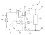
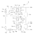
- the water heating system 2 of the second embodiment shown in FIG. 2 is basically the same as the water heating system 1 of the first embodiment, but has a heat radiating unit. Mainly different in 12.
- the heat radiating unit 12 of the first embodiment exchanges heat with the water of the water circuit 20 and another heat medium, while the heat radiating unit 12 of the second embodiment exchanges heat with the water of the water circuit 20.
- the heat radiating section 12 is configured to dissipate the heat of the refrigerant to the water flowing upstream of the water outlet section 32.
- the heat medium through which the refrigerant discharged from the compressor 11 is heat-exchanged is the water heated in the water heat exchanger 30.
- the heat radiating unit 12 is a portion arranged so as to approach the water pipe on the upstream side of the water heat exchanger 30 in the refrigerant pipe through which the refrigerant discharged from the compressor 11 flows.
- the refrigerant circuit 10 has a first refrigerant pipe 16 that connects the compressor 11 and the heat radiating portion 12, and a second refrigerant pipe 17 that connects the heat radiating portion 12 and the refrigerant inlet portion 33. ..
- the refrigerant discharged from the compressor 11 flows into the heat radiating unit 12 via the first refrigerant pipe 16.
- the heat radiating unit 12 dissipates the heat of the refrigerant discharged from the compressor 11 to the water in the water circuit 20.
- the refrigerant whose temperature has dropped due to heat radiated by the heat radiating unit 12 flows into the water heat exchanger 30 via the second refrigerant pipe 17.
- the condenser 13 of the water heat exchanger 30 dissipates heat from the water and condenses it.
- the refrigerant condensed in the condenser 13 expands in the expansion valve 14 and then flows into the evaporator 15.
- the evaporator 15 absorbs heat from the outside air and evaporates.
- the refrigerant circulates in this way, and the compression stroke, the condensation stroke, the expansion stroke, and the evaporation stroke are repeated.
- the water in the hot water storage tank 23 is heated by the circulation pump 21 by absorbing heat from the refrigerant flowing through the heat radiating unit 12 before being supplied to the heat absorber 22 of the water heat exchanger 30.
- the water heated by the heat radiating unit 12 flows into the water heat exchanger 30 and is heated by further absorbing heat from the refrigerant by the endothermic absorber 22.
- the hot water generated by heating returns to the hot water storage tank 23.
- the refrigerant compressed to a high temperature by the compressor 11 exchanges heat with the water flowing upstream of the water outlet portion 32, and then exchanges heat with the water in the water outlet portion 32 of the water heat exchanger 30.
- the water heating system 2 of the present embodiment is configured to dissipate the heat of the refrigerant to the water flowing upstream of the water outlet portion 32.
- the temperature of the water flowing upstream of the water outlet 32 is lower than the temperature of the water flowing through the water outlet 32.
- the heat radiating unit 12 can heat the low-temperature water on the upstream side with the refrigerant before being heated by the first heat exchange unit 35. Therefore, it is possible to prevent scale from adhering to the water heat exchanger 30 and to heat water efficiently.
- the water heating system 3 of the third embodiment shown in FIG. 3 is basically the same as the water heating system 2 of the second embodiment, but the water heat It is mainly different in the exchanger 30 and the heat radiating unit 12.
- the first heat exchange unit 35 and the second heat exchange unit 36 are arranged in one water heat exchanger 30 in the second embodiment, but are arranged in different water heat exchangers in the third embodiment. ..
- the water heating system 3 of the present embodiment includes a water heat exchanger including a first heat exchange unit 35 and a water heat exchanger including a second heat exchange unit 36.
- the heat radiating unit 12 includes a second heat exchange unit 36.
- the refrigerant circuit 10 includes a compressor 11, a first condenser 13a, a second condenser 13b, an expansion valve 14, and an evaporator 15. have.
- the compressor 11, the first condenser 13a, the second condenser 13b, the expansion valve 14, and the evaporator 15 are sequentially connected by a refrigerant pipe.
- the first refrigerant pipe 16 connects the compressor 11 and the first condenser 13a.
- the second refrigerant pipe 17 connects the first condenser 13a and the second condenser 13b.
- the third refrigerant pipe 18 connects the second condenser 13b and the evaporator 15.
- the first condenser 13a is arranged in the second heat exchange section 36 of the water heat exchanger 30. In the first condenser 13a, in the second heat exchange unit 36, heat exchange is performed between the refrigerant flowing through the first condenser 13a and the water flowing through the water circuit 20.
- the second condenser 13b is connected in series with the first condenser 13a.
- the second condenser 13b is arranged in the first heat exchange section 35 of the water heat exchanger 30.
- heat exchange is performed between the refrigerant flowing through the second condenser 13b and the water flowing through the water circuit 20.
- the heat dissipation unit 12 of this embodiment is the second heat exchange unit 36 in the refrigerant circuit 10. Therefore, the heat radiating unit 12 dissipates the heat of the refrigerant to the water flowing through the second heat exchange unit 36.
- the water circuit 20 includes a circulation pump 21, a first heat absorber 22a, a second heat absorber 22b, and a hot water storage tank 23.
- the circulation pump 21, the first heat absorber 22a, the second heat absorber 22b, and the hot water storage tank 23 are sequentially connected by water pipes.
- the first heat exchanger 22a is arranged in the second heat exchange section 36 of the water heat exchanger 30. In the first heat exchanger 22a, heat exchange is performed in the second heat exchange section 36 with the refrigerant flowing through the first condensing section 13a.
- the second heat absorber 22b is connected in series with the first heat absorber 22a.
- the second heat exchanger 22b is arranged in the first heat exchange section 35 of the water heat exchanger 30.
- heat exchange is performed between the water flowing through the second heat exchanger 22b and the water flowing through the refrigerant circuit 10 in the first heat exchange section 35 of the water heat exchanger 30.
- the water heat exchanger 30 is divided into a water heat exchanger composed of a first heat exchange unit 35 and a water heat exchanger composed of a second heat exchange unit 36.
- the first heat exchange unit 35 has a water outlet unit 32 and a refrigerant outlet unit 34.
- the water outlet portion 32 corresponds to the second heat absorber 22b
- the refrigerant outlet portion 34 corresponds to the second condenser 13b.
- the second heat exchange section 36 has a water inlet section 31 and a refrigerant inlet section 33.
- the water inlet portion 31 corresponds to the first heat absorber 22a
- the refrigerant inlet portion 33 corresponds to the first condenser 13a.
- the water flow direction and the refrigerant flow direction are in a countercurrent relationship.
- the flow direction of water and the flow direction of the refrigerant are in a countercurrent relationship.
- the flow direction of the refrigerant in the first heat exchange unit 35 and the flow direction of the refrigerant in the second heat exchange unit 36 are the same.
- the water flow direction in the first heat exchange unit 35 and the water flow direction in the second heat exchange unit 36 are the same.
- the water heat exchanger 30 is composed of two heat exchangers.
- the water outlet portion 32 is a portion in the vicinity of the outlet including the outlet located at the most downstream of the water circuit 20 in the water heat exchanger 30 composed of one or a plurality of heat exchangers.
- the refrigerant discharged from the compressor 11 flows into the second heat exchange unit 36 as the heat dissipation unit 12 via the first refrigerant pipe 16.
- the heat of the refrigerant discharged from the compressor 11 is dissipated to the water in the water circuit 20.
- the refrigerant whose temperature has dropped due to heat radiated by the heat radiating unit 12 flows into the first heat exchange unit 35 via the second refrigerant pipe 17.
- the first heat exchange unit 35 in the second condenser 13b, heat is dissipated to the water in the water circuit 20 and condensed.
- the refrigerant condensed in the first and second condensers 13 expands in the expansion valve 14 via the third refrigerant pipe 18, and then flows into the evaporator 15.
- the water in the hot water storage tank 23 flows into the second heat exchange section 36 by the circulation pump 21.
- the water in the water circuit 20 is heated by absorbing heat from the refrigerant in the first endothermic device 22a.
- the water heated by the heat radiating unit 12 flows into the first heat exchange unit 35 and is heated by further absorbing heat from the refrigerant by the second endothermic device 22b.
- the hot water generated by heating returns to the hot water storage tank 23.
- the refrigerant compressed to a high temperature by the compressor 11 exchanges heat with water in the second heat exchange unit 36, and then exchanges heat with the water outlet unit 32 of the first heat exchange unit 35.
- the water heat exchanger 30 of the water heating system 3 of the present embodiment has a second heat exchange unit 36 that exchanges heat with a refrigerant on the upstream side of the first heat exchange unit 35 in the water circuit 20. Including further.
- the heat radiating unit 12 includes a second heat exchange unit 36.
- the temperature of the water flowing through the second heat exchange unit 36 is lower than the temperature of the water flowing through the first heat exchange unit 35.
- the heat radiating unit 12 can heat the low-temperature water of the second heat exchange unit 36 with the refrigerant before the water is heated by the first heat exchange unit 35. Therefore, it is possible to realize a water heating system 3 capable of suppressing the adhesion of scale to the water heat exchanger 30 and efficiently heating water.
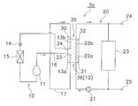
- the water heating system 3 of the above-described embodiment includes two separate water heat exchangers, but the water heating system 3a of this modified example shown in FIG. 4 has two separate water heat exchangers.
- the first heat exchange section 35 and the second heat exchange section 36 are divided by the refrigerant flow path of one water heat exchanger 30.
- the water heat exchanger 30 includes a first heat exchange unit 35 and a second heat exchange unit 36.
- the refrigerant circuit 10 inside the water heat exchanger 30 the refrigerant flow path passing through the first heat exchange unit 35 and the refrigerant flow path passing through the second heat exchange unit 36 are separated.
- the second refrigerant pipe 17 of the refrigerant circuit 10 causes the refrigerant flowing out from the first heat exchange section 35 to flow into the second heat exchange section 36 of the same water heat exchanger 30 as the first heat exchange section 35.
- each of the water heat exchangers in which the first heat exchange unit 35 and the second heat exchange unit 36 are divided by separating a plurality of water heat exchangers as in the water heating system 3 of the above-described embodiment is a plate.
- a type heat exchanger is preferably used.
- the water heat exchanger in which one water heat exchanger is divided into a first heat exchange section 35 and a second heat exchange section 36 by a refrigerant flow path as in the water heating system 3a of this modified example is a double pipe.
- a type heat exchanger is preferably used.
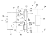
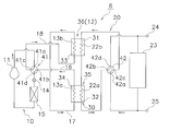
- the water heating system 4 of the fourth embodiment shown in FIGS. 5 and 6 is basically the same as the water heating system 3 of the third embodiment. , Mainly different in the refrigerant circuit 10.
- the water heating system 4 of the present embodiment can be defrosted for defrosting.
- the refrigerant circuit 10 further includes a bypass pipe 19 in which the refrigerant bypasses the first heat exchange unit 35 during the defrost operation.
- the refrigerant circuit 10 further includes a bypass pipe 19, a first valve B1, and a second valve B2.
- the bypass pipe 19 is connected to a second refrigerant pipe 17 that connects the first condenser 13a and the second condenser 13b, and a third refrigerant pipe 18 that connects the second condenser 13b and the expansion valve 14. ..
- the bypass pipe 19 the refrigerant flowing through the third refrigerant pipe 18 flows through the second refrigerant pipe 17 by bypassing the first heat exchange section 35 during the defrost operation.
- the first valve B1 is provided in the second refrigerant pipe 17.
- the second valve B2 is provided in the bypass pipe 19.
- the first valve B1 and the second valve B2 are on-off valves.
- FIG. 5 shows the flow of the refrigerant and water during the heating operation of the present embodiment. The operation of the heating operation of the water heating system 4 will be described with reference to FIG.
- the first valve B1 is fully open and the second valve B2 is fully closed.
- the refrigerant discharged from the compressor 11 flows into the second heat exchange section 36 as the heat dissipation section 12 through the first refrigerant pipe 16.
- the second heat exchange unit 36 in the first condenser 13a, the heat of the refrigerant discharged from the compressor 11 is dissipated to the water in the water circuit 20. Since the first valve B1 is open, the refrigerant radiated by the heat radiating unit 12 and whose temperature has dropped flows into the first heat exchange unit 35 through the second refrigerant pipe 17.
- the second condenser 13b heat is dissipated to the water in the water circuit 20 and condensed.
- the refrigerant condensed in the second condenser 13 expands in the expansion valve 14 through the third refrigerant pipe 18, and then flows into the evaporator 15.
- the water in the hot water storage tank 23 sequentially flows into the second heat exchange section 36 and the first heat exchange section 35 by the circulation pump 21.
- the water in the water circuit 20 is heated by the refrigerant in the second heat exchange section 36 and the first heat exchange section 35.
- the hot water generated by heating returns to the hot water storage tank 23.
- FIG. 6 shows the flow of the refrigerant and water during the defrost operation of the present embodiment.
- the water inlet portion 31, the water outlet portion 32, the refrigerant inlet portion 33, and the refrigerant outlet portion 34 are designated by reference numerals (same as in FIG. 5) based on the flow directions of the refrigerant and water during the heating operation.
- the operation of the defrost operation of the water heating system 4 will be described with reference to FIG.
- frost formation is detected due to a decrease in the temperature of the refrigerant in the evaporator 15 during the heating operation, a defrost operation is performed to dissolve the frost adhering to the evaporator 15.
- the first valve B1 is fully closed and the second valve B2 is fully open.
- the refrigerant discharged from the compressor 11 flows into the heat exchanger that functions as the evaporator 15 during the heating operation, dissipates heat to the outside air, and condenses.
- the refrigerant passes through the third refrigerant pipe 18 after expanding in the expansion valve 14, but since the first valve B1 is closed and the second valve B2 is open, the first heat exchange section 35 is bypassed and bypassed. Pass through pipe 19.
- the refrigerant flows into the second heat exchange section 36 through the second refrigerant pipe 17 connected to the bypass pipe 19. Then, the refrigerant is sucked into the compressor 11 through the flow path that functions as the first condensing portion 13a and the first refrigerant pipe 16 during the heating operation.
- the refrigerant circuit 10 further includes a bypass pipe 19 in which the refrigerant bypasses the first heat exchange unit 35 during the defrost operation.
- the amount of heat stored in the second heat exchange unit 36 having the high-temperature refrigerant can be used, so that the defrost operation time can be shortened.
- the water heating system 5 of the fifth embodiment shown in FIGS. 7 and 8 is basically the same as the water heating system 3 of the third embodiment. , Mainly different in the refrigerant circuit 10.
- the water heating system 5 of the present embodiment can be defrosted.
- the refrigerant circuit 10 further includes a bypass pipe 19 in which the refrigerant bypasses the second heat exchange unit 36 during the defrost operation.
- the refrigerant circuit 10 further includes a bypass pipe 19, a first valve B1, and a second valve B2.
- the bypass pipe 19 is connected to the first refrigerant pipe 16 that connects the compressor 11 and the first condenser 13a, and the second refrigerant pipe 17 that connects the first condenser 13a and the second condenser 13b. ..
- the bypass pipe 19 the refrigerant flowing through the second refrigerant pipe 17 flows through the first refrigerant pipe 16 by bypassing the second heat exchange section 36 during the defrost operation.
- the first valve B1 is provided in the second refrigerant pipe 17.
- the second valve B2 is provided in the bypass pipe 19.
- the first valve B1 and the second valve B2 are on-off valves.
- FIG. 7 shows the flow of the refrigerant and water during the heating operation of the present embodiment. The operation of the heating operation of the water heating system 4 will be described with reference to FIG. 7.
- the first valve B1 is fully open and the second valve B2 is fully closed.
- the refrigerant discharged from the compressor 11 flows into the second heat exchange section 36 as the heat dissipation section 12 through the first refrigerant pipe 16.
- the second heat exchange unit 36 in the first condenser 13a, the heat of the refrigerant discharged from the compressor 11 is dissipated to the water in the water circuit 20.
- the refrigerant whose temperature has dropped due to heat radiated by the heat radiating unit 12 flows into the first heat exchange unit 35 through the second refrigerant pipe 17.
- the second condenser 13b heat is dissipated to the water in the water circuit 20 and condensed.
- the refrigerant condensed in the second condenser 13 expands in the expansion valve 14 through the third refrigerant pipe 18, and then flows into the evaporator 15.
- the water in the hot water storage tank 23 sequentially flows into the second heat exchange section 36 and the first heat exchange section 35 by the circulation pump 21.
- the water in the water circuit 20 is heated by the refrigerant in the second heat exchange section 36 and the first heat exchange section 35.
- the hot water generated by heating returns to the hot water storage tank 23.
- FIG. 8 shows the flow of the refrigerant and water during the defrost operation of the present embodiment.
- the water inlet portion 31, the water outlet portion 32, the refrigerant inlet portion 33, and the refrigerant outlet portion 34 are designated with reference numerals (same as in FIG. 7) based on the flow directions of the refrigerant and water during the heating operation.
- the operation of the defrost operation of the water heating system 5 will be described with reference to FIG.
- the first valve B1 is fully closed and the second valve B2 is fully open.
- the refrigerant discharged from the compressor 11 flows into the heat exchanger that functions as the evaporator 15 during the heating operation, dissipates heat to the outside air, and condenses.
- the refrigerant flows into the first heat exchange section 35 through the third refrigerant pipe 18. Then, the refrigerant flows out from the first heat exchange unit 35 through the flow path that functions as the second condenser 13b during the heating operation.
- the refrigerant passes through the second refrigerant pipe 17, but since the first valve B1 is closed and the second valve B2 is open, the second heat exchange section 36 is bypassed and the refrigerant passes through the bypass pipe 19.
- the refrigerant is sucked into the compressor 11 through the first refrigerant pipe 16 connected to the bypass pipe 19.
- the refrigerant circuit 10 further includes a bypass pipe 19 in which the refrigerant bypasses the second heat exchange unit 36 during the defrost operation.
- the amount of heat stored by heat exchange with the high-temperature refrigerant can be used, so that the water can reach a predetermined temperature at an early stage during the heating operation.
- the refrigerant circuit 10 further includes a bypass pipe 19 in which the refrigerant bypasses the first heat exchange section 35 during the defrost operation.
- the refrigerant circuit 10 further includes a bypass pipe 19 in which the refrigerant bypasses the second heat exchange unit 36 during the defrost operation.
- the refrigerant circuit 10 further includes a bypass pipe 19 in which the refrigerant bypasses the first heat exchange unit 35 and the second heat exchange unit 36 during the defrost operation.
- the water heating system of this modification has the same configuration as the water heating system of the first embodiment shown in FIG. 1, but differs in that the refrigerant circuit 10 further includes a bypass pipe 19.
- the bypass pipe 19 of this modification is connected to the second refrigerant pipe 17 that connects the heat radiating unit 12 and the condenser 13, and the third refrigerant pipe 18 that connects the condenser 13 and the expansion valve 14.
- the heating operation can be performed by closing the second valve B2 provided in the bypass pipe 19 and opening the first valve B1 provided in the second refrigerant pipe 17.
- the defrost operation can be performed by opening the second valve B2 provided in the bypass pipe 19 and closing the first valve B1 provided in the second refrigerant pipe 17.
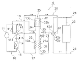
- the water heating system 6 of the sixth embodiment shown in FIGS. 10 and 11 is basically the same as the water heating system 3 of the third embodiment. , Mainly different in the refrigerant circuit 10 and the water circuit 20. In the water heating system 6 of the present embodiment, at least one of the refrigerant circuit 10 and the water circuit 20 is configured to circulate the flow directions of the refrigerant and water in opposite directions.
- the refrigerant circuit 10 further includes a switching mechanism 41.
- the switching mechanism 41 is a flow path switching mechanism that switches the flow of the refrigerant in the refrigerant circuit 10.
- the switching mechanism 41 is a four-way switching valve.
- the switching mechanism 41 switches the flow direction of the refrigerant between the first direction and the second direction opposite to the first direction.
- the switching mechanism 41 communicates the first port 41a and the second port 41b as shown by the solid line of the switching mechanism 41 in FIG.
- the port 41c and the fourth port 41d are communicated with each other.
- the compressor 11 and the first condenser 13a are connected, and the second condenser 13b and the expansion valve 14 are connected.
- the switching mechanism 41 communicates the first port 41a and the third port 41c and the second port as shown by the solid line of the switching mechanism in FIG.
- the 41b and the fourth port 41d are communicated with each other.
- the compressor 11 and the second condenser 13b are connected, and the first condenser 13a and the expansion valve 14 are connected.
- the water circuit 20 further includes a switching mechanism 42.
- the switching mechanism 42 is a flow path switching mechanism that switches the flow of water in the water circuit 20.
- the switching mechanism 42 is a four-way switching valve.
- the switching mechanism 42 switches the water flow direction between the first direction and the second direction opposite to the first direction.
- the switching mechanism 42 communicates the first port 42a and the second port 42b as shown by the solid line of the switching mechanism 42 in FIG.
- the port 42c and the fourth port 42d are communicated with each other.
- the water supply port to the water heat exchanger 30 in the hot water storage tank 23 and the first heat absorber 22a are connected, and the hot water receiving port from the water heat exchanger 30 in the hot water storage tank 23 and the second heat absorber 22b are connected. Is connected.
- the switching mechanism 42 communicates the first port 42a and the third port 42c and the second port as shown by the solid line of the switching mechanism in FIG.
- the 42b and the fourth port 42d are communicated with each other.
- the water supply port to the water heat exchanger 30 and the second heat absorber 22b are connected, and the hot water receiving port from the water heat exchanger 30 in the hot water storage tank 23 and the first heat absorber 22a are connected.
- the upper water heat exchanger in FIG. 10 constitutes the first heat exchange section 35, and the lower water heat exchanger in FIG. 10 is the second heat.
- the exchange unit 36 is configured.
- the lower water heat exchanger in FIG. 11 constitutes the first heat exchange section 35, and the upper water heat exchanger in FIG. 11 is the second heat.
- the exchange unit 36 is configured.
- the water heating system 6 of the present embodiment includes a first heating operation in which the refrigerant and water flow in the first direction and a second heating operation in which the refrigerant and water flow in the second direction. ,It can be performed.
- the first heating operation and the second heating operation can be appropriately selected.
- the first heating operation and the second heating operation are alternately switched at a predetermined operation time.
- FIG. 10 shows the flow of the refrigerant and water in the first direction of the present embodiment. With reference to FIG. 10, the operation of the heating operation when the refrigerant and water flow in the first direction of the water heating system 6 will be described.
- the refrigerant discharged from the compressor 11 passes through the first port 41a to the second port 41b and exchanges second heat as the heat radiating unit 12. It flows into the part 36.
- the heat of the refrigerant discharged from the compressor 11 is dissipated to the water in the water circuit 20.
- the refrigerant whose temperature has dropped due to heat radiated by the heat radiating unit 12 flows into the first heat exchange unit 35 via the second refrigerant pipe 17.
- the first heat exchange unit 35 in the second condenser 13b, heat is dissipated to the water in the water circuit 20 and condensed.
- the refrigerant condensed in the second condenser 13b passes through the third port 41c through the fourth port 41d, expands in the expansion valve 14, and then flows into the evaporator 15.
- the water in the hot water storage tank 23 flows from the first port 42a through the second port 42b to the second heat exchange unit 36.
- the water in the water circuit 20 is heated by absorbing heat from the refrigerant by the heat radiating unit 12 in the first endothermic device 22a.
- the water heated by the heat radiating unit 12 flows into the first heat exchange unit 35 and is heated by further absorbing heat from the refrigerant by the second endothermic device 22b.
- the hot water generated by heating returns to the hot water storage tank 23 from the third port 42c through the fourth port 42d.
- FIG. 11 shows the flow of the refrigerant and water in the second direction of the present embodiment. With reference to FIG. 11, the operation of the heating operation when the refrigerant and water flow in the second direction of the water heating system 6 will be described.
- the refrigerant discharged from the compressor 11 passes through the first port 41a to the third port 41c and exchanges second heat as the heat radiating unit 12. It flows into the part 36.
- the heat of the refrigerant discharged from the compressor 11 is dissipated to the water in the water circuit 20.
- the refrigerant whose temperature has dropped due to heat radiated by the heat radiating unit 12 flows into the first heat exchange unit 35 via the second refrigerant pipe 17.
- the first heat exchange unit 35 in the first condenser 13a, heat is dissipated to the water in the water circuit 20 and condensed.
- the refrigerant condensed in the first condenser 13a passes from the second port 41b through the fourth port 41d, expands in the expansion valve 14, and then flows into the evaporator 15.
- the water in the hot water storage tank 23 flows from the first port 42a through the third port 42c to the second heat exchange unit 36.
- the water in the water circuit 20 is heated by absorbing heat from the refrigerant by the heat radiating unit 12 in the second endothermic device 22b.
- the water heated by the heat radiating unit 12 flows into the first heat exchange unit 35 and is heated by further absorbing heat from the refrigerant by the first endothermic device 22a.
- the hot water generated by heating passes from the second port 42b through the fourth port 42d and returns to the hot water storage tank 23.
- the refrigerant circuit 10 and the water circuit 20 are configured to circulate the flow directions of the refrigerant and water in opposite directions. By reverse circulation in this way, even if the scale adheres, the scale can be dispersed, so that the life of the water heat exchanger 30 can be extended.
- both the refrigerant circuit 10 and the water circuit 20 reverse the flow directions of the refrigerant and water. Is also configured to circulate.
- the refrigerant circuit 10 is configured to circulate in the opposite direction of the refrigerant flow, but the water circuit 20 has a constant water flow direction.
- the water circuit 20 is configured to circulate in the opposite direction of the water flow direction, the refrigerant flow direction of the refrigerant circuit 10 may be constant.
- the switching mechanism 41 of the refrigerant circuit 10 and the switching mechanism 42 of the water circuit 20 are four-way switching valves, but the present invention is not limited thereto.
- the switching mechanism 42 of the water circuit 20 of this modification is a two-way switching valve or a reverse circulation pump.
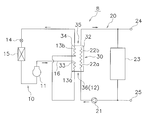
- the water heating system 7 of the seventh embodiment shown in FIG. 12 is basically the same as the water heating system 3 of the third embodiment, but has a water circuit. Mainly different at 20.
- the water circuit 20 further includes a take-out portion 37 for taking out water from between the water inlet portion 31 and the water outlet portion 32 of the water heat exchanger 30.
- the water circuit 20 further includes a take-out portion 37, a third valve B3, a fourth valve B4, and a medium-temperature water tank 23b.
- the hot water storage tank 23 of the third embodiment shown in FIG. 3 corresponds to the high temperature water tank 23a of the present embodiment shown in FIG.
- the medium hot water tank 23b stores water having a temperature lower than the temperature of the water stored in the high temperature water tank 23a.
- the take-out portion 37 of the present embodiment is a pipe that branches from between the first heat absorber 22a and the second heat absorber 22b and is connected to the receiving port of the medium-temperature water tank 23b in the water circuit 20.
- the medium hot water tank 23b receives medium hot water from the take-out unit 37.
- the medium-temperature water tank 23b is connected to the first water pipe 38 that supplies the water heat exchanger 30. Therefore, the water circuit 20 has a first water circuit that circulates in the high temperature water tank 23a and a second water circuit that circulates in the medium hot water tank 23b.
- the first water pipe 38 may be omitted, and the medium-temperature water tank 23b may be composed of a first water circuit that only receives medium-temperature water.
- the third valve B3 is provided in the take-out section 37.
- the fourth valve B4 is provided in the water pipe 39 connecting the second heat absorber 22b and the high temperature water tank 23a.
- the third valve B3 and the fourth valve B4 are on-off valves.
- the water circuit 20 may further have a water pipe (not shown) that bypasses the high temperature water to the medium hot water.
- the water in the high temperature water tank 23a and the medium hot water tank 23b flows into the second heat exchange section 36 by the circulation pump 21.
- the water in the water circuit 20 is heated by absorbing heat from the refrigerant by the heat radiating unit 12 in the first endothermic device 22a.
- a part of the water heated by the heat radiating unit 12 flows into the first heat exchange unit 35 and is heated by further absorbing heat from the refrigerant by the second endothermic device 22b.
- the high-temperature water generated by heating flows into the high-temperature water tank 23a.
- the remaining water heated by the heat radiating unit 12 flows into the medium-temperature water tank 23b as medium-temperature water via the take-out unit 37.
- the water heating system 7 of the present embodiment can perform a heating operation for taking out medium-temperature water and high-temperature water.
- the ratio of medium hot water to high temperature water can be arbitrarily changed by adjusting the opening degree of the third valve B3 and the fourth valve B4.
- the water circuit 20 further has a take-out portion 37 for taking out water from between the water inlet portion 31 and the water outlet portion 32 of the water heat exchanger 30. ing.
- the high-temperature water of the water outlet portion 32 heated by the refrigerant in the water heat exchanger 30 and the medium-temperature water between the water outlet portion 32 and the water inlet portion 31 can be taken out.
- the refrigerant circuit 10 of the present embodiment is basically the same as the refrigerant circuit 10 of the water heating system 3a shown in FIG. 4, but the refrigerant outlet is one end of the water heat exchanger 30 (FIG. It differs in that it is located at the upper end of 12).
- the refrigerant flows upward and the water flows upward. Therefore, in the first heat exchange unit 35, the water and the refrigerant are heat-exchanged in a parallel flow.
- the refrigerant flows downward and the water flows upward. Therefore, in the second heat exchange unit 36, the water and the refrigerant exchange heat with each other in a countercurrent flow.
- the water heating system 8 of the present embodiment in at least a part of the water heat exchanger 30, the water flow direction and the refrigerant flow direction are in a parallel flow relationship.
- the water flow direction and the refrigerant flow direction are in a parallel flow relationship.
- the water heating system 8 can configure the water heat exchanger 30 so that the refrigerant and water exchange heat with a countercurrent and / or a parallel flow.
- the water heating system 9 of the ninth embodiment shown in FIG. 14 includes a plurality of refrigerant circuits 10a and 10b and a plurality of water circuits 20a and 20b. There is.
- the refrigerant circuit 10a and the water circuit 20a share a water heat exchanger 30a.
- the refrigerant circuit 10b and the water circuit 20a share the water heat exchanger 30b.
- the refrigerant circuit 10b and the water circuit 20b share a water heat exchanger 30c.
- the refrigerant circuit 10a shown on the upper side of FIG. 14 is the same as the refrigerant circuit 10 of the modified example of the third embodiment shown in FIG. Specifically, in the refrigerant circuit 10, the compressor 11a, the first condenser 13a-1 as the heat radiating portion 12a, the second condenser 13a-2, the expansion valve 14a, and the evaporator 15a are sequentially arranged. , Connected by refrigerant piping.
- the refrigerant circuit 10b shown on the lower side of FIG. 14 includes a compressor 11b, a first condenser 13b-1 as a heat radiating portion 12b, a second condenser 13b-2, an expansion valve 14b, an evaporator 15b, and the like. have.
- the compressor 11b, the first condenser 13b-1 as the heat radiating portion 12b, the second condenser 13b-2, the expansion valve 14b, and the evaporator 15b are sequentially connected by a refrigerant pipe. Has been done.
- the water circuit 20a shown on the upper side of FIG. 14 is the same as the water circuit 20 of the third embodiment shown in FIG. Specifically, in the water circuit 20a, the circulation pump 21, the first heat absorber 22a-1, the second heat absorber 22a-2, and the hot water storage tank 23a are sequentially connected by water pipes. High temperature water is stored in the hot water storage tank 23a.
- the water circuit 20b shown on the lower side of FIG. 14 is the same as the water circuit 20 of the first embodiment shown in FIG. Specifically, in the water circuit 20b, the circulation pump 21, the heat absorber 22b, and the hot water storage tank 23b are sequentially connected by water pipes. Medium hot water is stored in the hot water storage tank 23b.
- the upper water heat exchanger 30a in FIG. 14 constitutes the first heat exchange unit 35 in relation to the central water heat exchanger 30b. Looking at the water heat exchanger 30a alone, the first heat exchange section 35, where the second condenser 13a-2 and the water outlet section 32 exchange heat, and the first condenser 13a-1 and the water inlet section 31 heat. Includes a second heat exchange unit 36 to be replaced.
- the water heat exchanger 30b in the center of FIG. 14 constitutes the second heat exchange unit 36 in relation to the water heat exchanger 30a. Further, the water heat exchanger 30b constitutes a second heat exchange unit 36 in relation to the water heat exchanger 30c on the lower side of FIG.
- the water heat exchanger 30c on the lower side of FIG. 14 constitutes the first heat exchange unit 35 in relation to the water heat exchanger 30b.
- the refrigerant discharged from the compressor 11a exchanges the second heat of the water heat exchanger 30a as the heat radiating portion 12a via the first refrigerant pipe 16a. It flows into the part 36.
- the heat of the refrigerant discharged from the compressor 11a is dissipated to the water in the water circuit 20a in the first condenser 13a-1 as the heat dissipation section 12a.
- the refrigerant whose temperature has dropped due to heat radiated by the heat radiating unit 12a flows into the first heat exchange unit 35 of the water heat exchanger 30a via the second refrigerant pipe 17a.
- the second condenser 13a-2 heat is dissipated to the water in the water circuit 20a and condensed.
- the refrigerant condensed in the first and second condensers 13a expands in the expansion valve 14 via the third refrigerant pipe 18a and then flows into the evaporator 15.
- the refrigerant discharged from the compressor 11b flows into the water heat exchanger 30b as the heat radiating unit 12b via the first refrigerant pipe 16b.
- the water heat exchanger 30b is a second heat exchange unit 36, and in the first condenser 13b-1 of the water heat exchanger 30b, the heat of the refrigerant discharged from the compressor 11a is radiated to the water of the water circuit 20a.
- the refrigerant whose temperature has dropped due to heat radiated by the heat radiating unit 12b flows into the water heat exchanger 30c via the second refrigerant pipe 17b.
- the water heat exchanger 30c is the first heat exchange unit 35, and in the second condenser 13b-2 of the water heat exchanger 30c, heat is dissipated to the water in the water circuit 20b and condensed.
- the refrigerant condensed in the first and second condensers 13b expands in the expansion valve 14b via the third refrigerant pipe 18b, and then flows into the evaporator 15b.
- the water in the hot water storage tank 23a flows into the water heat exchanger 30b by the circulation pump 21a.
- the water heat exchanger 30b is the second heat exchange unit 36, and the water in the water circuit 20a is heated by absorbing heat from the refrigerant by the heat radiating unit 12b in the first endothermic absorber 22a-1.
- the water heated by the heat radiating unit 12b flows into the water heat exchanger 30a.
- water is heated by further absorbing heat from the refrigerant by the second endothermic device 22a-2 of the second heat exchange section 36 and the first heat exchange section 35.
- the hot water generated by heating returns to the hot water storage tank 23.
- the water in the hot water storage tank 23b flows into the second heat exchange section 36 of the water heat exchanger 30c by the circulation pump 21b.
- the water in the water circuit 20b is heated by absorbing heat from the refrigerant radiated by the water heat exchanger 30b as the heat dissipation section 12b.
- the medium hot water generated by heating returns to the hot water storage tank 23.
- the water heating system 9 of the present embodiment has a plurality of evaporators 15.
- the evaporator 15 is an outdoor unit.
- the water heating system 9 of the present disclosure can be applied to a system having a plurality of outdoor units.
Landscapes
- Engineering & Computer Science (AREA)
- Physics & Mathematics (AREA)
- Thermal Sciences (AREA)
- Mechanical Engineering (AREA)
- General Engineering & Computer Science (AREA)
- Chemical & Material Sciences (AREA)
- Combustion & Propulsion (AREA)
- Heat-Pump Type And Storage Water Heaters (AREA)
Abstract
水加熱システム(1)は、冷媒回路(10)と、水回路(20)と、を備える。冷媒回路(10)は、圧縮機(11)を有し、冷媒が流れる。水回路(20)は、水が流れる。冷媒回路(10)及び水回路(20)は、圧縮機(11)から吐出された冷媒により水を加熱する水熱交換器(30)を共有する。水熱交換器(30)は、第1熱交換部(35)を含む。第1熱交換部(35)は、水出口部(32)の水と冷媒とが熱交換を行う。冷媒回路(10)は、放熱部(12)をさらに有する。放熱部(12)は、圧縮機(11)と第1熱交換部(35)との間に配置され、圧縮機(11)から吐出された冷媒の熱を放熱させる。
Description
水加熱システムに関する。
従来、冷媒により水を加熱する水熱交換器を備える水加熱システムが知られている。水加熱システムでは、水熱交換器において、水が加熱されることによって、スケールが付着する場合がある。水熱交換器にスケールが付着することを想定した技術として、例えば、特許文献1(特開2015-17761号公報)に開示のヒートポンプ給湯システムが挙げられる。
特許文献1に開示のヒートポンプ給湯システムは、水熱交換器を高温側水熱交換器と低温側水熱交換器とに分割し、高温側水熱交換器の温水出口側に出湯温度センサを設けるとともに、低温側水熱交換器の出口側に温水温度センサを設けている。そして、高温側水熱交換器のスケール付着による性能低下時、低温側水熱交換器の出口温水温度センサの検出値が設定値を超えたとき、その温水出口温度を設定値以下に抑制制御するとともに、出湯温度の低下情報及び高温側水熱交換器のメンテナンス情報を出力する制御部を備えている。
しかしながら、上記特許文献1では、スケールの付着を高温側水熱交換器に止め、低温側水熱交換器への波及を防止している。このように、特許文献1では、高温水側熱交換器にスケールを付着させている。この場合、高温水側熱交換器の洗浄または交換の頻度が高くなり、費用を要してしまう。
第1観点に係る水加熱システムは、冷媒回路と、水回路と、を備える。冷媒回路は、圧縮機を有し、冷媒が流れる。水回路は、水が流れる。冷媒回路及び水回路は、圧縮機から吐出された冷媒により水を加熱する水熱交換器を共有する。水熱交換器は、第1熱交換部を含む。第1熱交換部は、水出口部の水と冷媒とが熱交換を行う。冷媒回路は、放熱部をさらに有する。放熱部は、圧縮機と第1熱交換部との間に配置され、圧縮機から吐出された冷媒の熱を放熱させる。
第1観点に係る水加熱システムでは、水出口部の水と冷媒とが熱交換を行う第1熱交換部は、水熱交換器において水が高温になる部分である。しかし、第1観点に係る水加熱システムでは、圧縮機と第1熱交換部との間に、冷媒の熱を放熱させる放熱部を配置している。放熱部により、冷媒が第1熱交換部に流入する前に放熱するので、第1熱交換部に流入する冷媒の温度を下げることができる。このため、第1熱交換部において、水出口部の水の温度が上昇することを抑制できる。したがって、水熱交換器にスケールが付着することを抑制できる。
第2観点に係る水加熱システムは、第1観点の水加熱システムであって、放熱部は、冷媒の熱を放熱させる蓄熱材を含む。
第2観点に係る水加熱システムでは、水熱交換器にスケールが付着することを抑制するとともに、冷媒の熱を蓄熱材に蓄熱させることができる。
第3観点に係る水加熱システムは、第1観点または第2観点の水加熱システムであって、冷媒の熱を大気に放熱させる放熱装置を含む。
第3観点に係る水加熱システムでは、水熱交換器にスケールが付着することを抑制するとともに、冷媒の熱を大気に放熱させることができる。
第4観点に係る水加熱システムは、第1観点から第3観点の水加熱システムであって、冷媒の熱を、水出口部よりも上流側を流れる水に放熱させるように構成されている。
第4観点に係る水加熱システムでは、水出口部よりも上流側を流れる水の温度は、水出口部を流れる水の温度よりも低い。ここでは、放熱部により、第1熱交換部で加熱される前に、上流側の低温の水を冷媒で加熱できる。したがって、水熱交換器にスケールが付着することを抑制するとともに、水を効率よく加熱することができる。
第5観点に係る水加熱システムは、第4観点の水加熱システムであって、水熱交換器は、水回路において第1熱交換部よりも上流側で冷媒と熱交換を行う第2熱交換部をさらに含む。放熱部は、第2熱交換部を含む。
第5観点に係る水加熱システムでは、第2熱交換部を流れる水の温度は、第1熱交換部を流れる水の温度よりも低い。ここでは、放熱部により、第1熱交換部で水が加熱される前に、第2熱交換部の低温の水を冷媒で加熱できる。したがって、水熱交換器にスケールが付着することを抑制するとともに、水を効率よく加熱することができる水加熱システムを実現できる。
第6観点に係る水加熱システムは、第5観点の水加熱システムであって、冷媒回路は、デフロスト運転時に、第1熱交換部または第2熱交換部の一方を冷媒がバイパスするバイパス管をさらに有する。
第6観点に係る水加熱システムでは、デフロスト運転時に第1熱交換部をバイパスすることにより、高温の冷媒を有する第2熱交換部で蓄熱した熱量を用いることができるので、デフロスト運転時間を短縮できる。デフロスト運転時に第2熱交換部をバイパスすることにより、高温の冷媒との熱交換によって蓄熱された熱量を用いることができるので、加熱運転時に早期に水を所定温度に到達させることができる。
第7観点に係る水加熱システムは、第1観点から第6観点の水加熱システムであって、水熱交換器の少なくとも一部において、水の流れ方向と、冷媒の流れ方向とは、対向流の関係にある。
第7観点に係る水加熱システムでは、冷媒と水とを対向流で流すことによって、熱交換効率を向上することができる。
第8観点に係る水加熱システムは、第1観点から第7観点の水加熱システムであって、冷媒回路及び水回路の少なくとも一方は、冷媒及び水の流れ方向を逆方向にも循環させるように構成されている。
第8観点に係る水加熱システムでは、逆循環させることにより、仮にスケールが付着しても、スケールを分散できるので、水熱交換器の寿命を長くすることができる。
第9観点に係る水加熱システムは、第1観点から第8観点の水加熱システムであって、水回路は、水熱交換器の水入口部と水出口部との間から水を取り出す取出部をさらに有する。
第9観点に係る水加熱システムでは、水熱交換器において冷媒に加熱された、水出口部の高温水と、水出口部と水入口部との間の中温水と、を取り出すことができる。。
本開示の一実施形態に係る水加熱システムについて、図面を参照しながら説明する。
(1)第1実施形態
(1-1)全体構成
本開示の一実施形態に係る水加熱システム1は、冷媒によって水を加熱する。本実施形態の水加熱システム1は、給湯システムである。
(1-1)全体構成
本開示の一実施形態に係る水加熱システム1は、冷媒によって水を加熱する。本実施形態の水加熱システム1は、給湯システムである。
図1に示すように、水加熱システム1は、冷媒回路10と、水回路20と、を備える。冷媒回路10及び水回路20は、冷媒により水を加熱する水熱交換器30を共有する。
(1-2)詳細構成
(1-2-1)冷媒回路
冷媒回路10は、冷媒が流れる。冷媒回路10には、冷媒として、例えばR32を含む流体が封入されている。
(1-2-1)冷媒回路
冷媒回路10は、冷媒が流れる。冷媒回路10には、冷媒として、例えばR32を含む流体が封入されている。
冷媒回路10は、圧縮機11と、放熱部12と、凝縮器13と、膨張弁14と、蒸発器15と、を有している。冷媒回路10において、圧縮機11と、放熱部12と、凝縮器13と、膨張弁14と、蒸発器15と、が順次、冷媒配管で接続されている。
圧縮機11は、低圧の冷媒を高圧になるまで圧縮する機器である。本実施形態の圧縮機11は、インバータ回路により回転数を制御し、冷媒の吐出量を調整できるタイプの圧縮機である。
放熱部12は、圧縮機11から吐出された冷媒の熱を放熱させる。このため、放熱部12を通った冷媒の温度は下がる。放熱部12は、後述する水熱交換器30の第1熱交換部35と圧縮機11との間に配置される。
放熱部12は、水回路20の水と別の熱媒体と熱交換する。本実施形態の放熱部12は、冷媒の熱を放熱させる蓄熱材及び冷媒の熱を大気に放熱させる放熱装置の少なくとも一方を含む。放熱部12において、冷媒の熱を蓄熱材及び大気の少なくとも一方に放熱させる。
凝縮器13は、熱交換により、冷媒回路10を流れる冷媒を凝縮液化させるものである。本実施形態では、凝縮器13は、水熱交換器30において冷媒回路10を流れる冷媒が通過する伝熱管等により構成される。水熱交換器30において、凝縮器13を流れる冷媒と、水回路20を流れる水との間で熱交換が行われる。
膨張弁14は、冷媒回路10を流れる冷媒を減圧して膨張させるものであり、例えば、電子式膨張弁である。
蒸発器15は、熱交換により、冷媒回路10を流れる冷媒を蒸発させるものである。本実施形態の蒸発器15は、外気と冷媒との熱交換を行う室外機である。
(1-2-2)水回路
水回路20は、水が流れる。水回路20は、循環ポンプ21と、吸熱器22と、貯湯タンク23と、を有している。水回路において、循環ポンプ21と、吸熱器22と、貯湯タンク23と、が順次、水配管で接続されている。
水回路20は、水が流れる。水回路20は、循環ポンプ21と、吸熱器22と、貯湯タンク23と、を有している。水回路において、循環ポンプ21と、吸熱器22と、貯湯タンク23と、が順次、水配管で接続されている。
水回路20は、水から温水を生成する給湯用温水回路である。水回路20では、水熱交換器30の吸熱器22で加熱された温水が、貯湯タンク23に蓄えられるように、水または温水が循環する。
循環ポンプ21は、水を循環させる。吸熱器22は、熱交換により、水回路20を流れる水を加熱するものである。本実施形態では、吸熱器22は、水熱交換器30において水回路20を流れる水が通過する伝熱管等により構成される。水熱交換器30において、吸熱器22を流れる水と、冷媒回路10を流れる冷媒との間で熱交換が行われる。貯湯タンク23は、吸熱器22で加熱された温水を蓄える。
水回路20には、貯湯タンク23における給排水を行うため、貯湯タンク23への給水管24と、貯湯タンク23からの出湯管25と、が接続される。
なお、水回路20は、スケールを捕捉するためのスケールトラップをさらに有してもよい。
(1-2-3)水熱交換器
水熱交換器30は、冷媒回路10の放熱部12と水回路20の吸熱器22とが一体に構成されている。水熱交換器30において、放熱部12を流れる冷媒と、吸熱器22を流れる水との間で熱交換が行われる。
水熱交換器30は、冷媒回路10の放熱部12と水回路20の吸熱器22とが一体に構成されている。水熱交換器30において、放熱部12を流れる冷媒と、吸熱器22を流れる水との間で熱交換が行われる。
水熱交換器30は、水回路20において、水入口部31と、水出口部32と、を含む。水入口部31は、水熱交換器30における水回路20の入口近傍である。水出口部32は、水熱交換器30における水回路20の出口近傍である。
水熱交換器30は、冷媒回路10において、冷媒入口部33と、冷媒出口部34と、を含む。冷媒入口部33は、水熱交換器30における冷媒回路10の入口近傍である。冷媒出口部34は、水熱交換器30における冷媒回路10の出口近傍である。
水熱交換器30において、水の流れ方向と、冷媒の流れ方向とは、対向流の関係にある。図1では、水熱交換器30において、冷媒の流れ方向は下向きであり、水の流れ方向は上向きである。
また、水熱交換器30は、第1熱交換部35と、第2熱交換部36と、を含む。図1では、水熱交換器30の上側が第1熱交換部35で、水熱交換器30の下側が第2熱交換部36である。
第1熱交換部35は、水出口部32の水と冷媒とが熱交換を行う。第1熱交換部35は、水熱交換器30の水回路20における下流側の部分で冷媒と熱交換を行う。ここでは、第1熱交換部35は、水出口部32の水と、冷媒入口部33の冷媒とが熱交換を行う。
第2熱交換部36は、水回路20において第1熱交換部35よりも上流側で冷媒と熱交換を行う。第2熱交換部36は、水入口部31の水と冷媒とが熱交換を行う。ここでは、第2熱交換部36は、水入口部31の水と、冷媒出口部34の冷媒とが熱交換を行う。
水熱交換器30は、例えば、二重管式熱交換器、プレート式熱交換器などを採用することができる。二重管式熱交換器は、内部に冷媒流路または水流路が形成された内管と、内管の外側に設けられ内管との間に水流路または冷媒流路を形成する外管と、を含む熱交換器である。プレート式熱交換器は、積層された複数のプレート間に水流路または流体流路が交互に形成された熱交換器である。
(1-3)水加熱システムの運転動作
次に、水加熱システム1の運転動作について説明する。
次に、水加熱システム1の運転動作について説明する。
冷媒回路10では、圧縮機11から吐出された冷媒は、放熱部12へ流入する。放熱部12では、圧縮機11から吐出された冷媒の熱を放熱させる。放熱部12で放熱して温度が低下した冷媒は、水熱交換器30に流入する。水熱交換器30の凝縮器13で水から放熱して凝縮する。凝縮器13で凝縮した冷媒は、膨張弁14において膨張した後、蒸発器15に流入する。冷媒は、蒸発器15で外気から吸熱して蒸発する。冷媒回路10では、このように冷媒が循環して、圧縮行程、凝縮行程、膨張行程及び蒸発行程を繰り返す。圧縮行程と凝縮行程との間に、放熱部12おいて冷媒が放熱される。
水回路20では、循環ポンプ21により貯湯タンク23の水が水熱交換器30の吸熱器22に供給され、冷媒から吸熱することによって、加熱される。加熱によって生成された温水は、貯湯タンク23に戻り、所定の蓄熱温度になるまで水回路20内で温水の循環が継続される。
このように、圧縮機11で高温に圧縮された冷媒は、放熱部12で加熱する水以外の熱媒体と熱交換した後に、水熱交換器30の水出口部32の水と熱交換している。
(1-4)特徴
本実施形態の水加熱システム1は、冷媒回路10と、水回路20と、を備える。冷媒回路10は、圧縮機11を有し、冷媒が流れる。水回路20は、水が流れる。冷媒回路10及び水回路20は、圧縮機11から吐出された冷媒により水を加熱する水熱交換器30を共有する。水熱交換器30は、第1熱交換部35を含む。第1熱交換部35は、水出口部32の水と冷媒とが熱交換を行う。冷媒回路10は、放熱部12をさらに有する。放熱部12は、圧縮機11と第1熱交換部35との間に配置され、圧縮機11から吐出された冷媒の熱を放熱させる。
本実施形態の水加熱システム1は、冷媒回路10と、水回路20と、を備える。冷媒回路10は、圧縮機11を有し、冷媒が流れる。水回路20は、水が流れる。冷媒回路10及び水回路20は、圧縮機11から吐出された冷媒により水を加熱する水熱交換器30を共有する。水熱交換器30は、第1熱交換部35を含む。第1熱交換部35は、水出口部32の水と冷媒とが熱交換を行う。冷媒回路10は、放熱部12をさらに有する。放熱部12は、圧縮機11と第1熱交換部35との間に配置され、圧縮機11から吐出された冷媒の熱を放熱させる。
本実施形態の水加熱システム1では、水出口部32の水と冷媒とが熱交換を行う第1熱交換部35は、水熱交換器30の水回路20において水が最も高温になる部分である。ここでは、圧縮機11と第1熱交換部35との間に、冷媒の熱を放熱させる放熱部12を配置している。放熱部12により、冷媒が第1熱交換部35に流入する前に放熱するので、第1熱交換部35に流入する冷媒の温度を下げることができる。これにより、第1熱交換部35において、水出口部32の水の温度が上昇することを抑制できる。このため、第1熱交換部35の水出口部32の表面の温度が上昇することを抑制できる。したがって、水熱交換器30にスケールが付着することを抑制できる。
このように、本実施形態の水加熱システムでは、水熱交換器30にスケールが付着することを抑制できるので、水熱交換器30を洗浄または交換する頻度を減らすことができる。
水加熱システム1において、放熱部12は、冷媒の熱を放熱させる蓄熱材を含んでもよい。この場合、水熱交換器30にスケールが付着することを抑制するとともに、冷媒の熱を蓄熱材に蓄熱させることができる。
また水加熱システム1は、冷媒の熱を大気に放熱させる放熱装置を含んでもよい。この場合、水熱交換器30にスケールが付着することを抑制するとともに、冷媒の熱を大気に放熱させることができる。
ここでは、水熱交換器30の少なくとも一部において、水の流れ方向と、冷媒の流れ方向とは、対向流の関係にある。冷媒と水とを対向流で流すことによって、熱交換効率を向上することができる。
(1-5)第1実施形態の変形例
上述した第1実施形態の放熱部12は、蓄熱材及び放熱装置の少なくとも一方を含むが、放熱部12は、水回路20の水と別の熱媒体と熱交換するものであれば、特に限定されない。本変形例では、冷媒回路10は複数の室外機を有し、少なくとも1つの室外機は蒸発器として使用され、他の室外機は放熱部12として使用される。
上述した第1実施形態の放熱部12は、蓄熱材及び放熱装置の少なくとも一方を含むが、放熱部12は、水回路20の水と別の熱媒体と熱交換するものであれば、特に限定されない。本変形例では、冷媒回路10は複数の室外機を有し、少なくとも1つの室外機は蒸発器として使用され、他の室外機は放熱部12として使用される。
(2)第2実施形態
(2-1)全体構成
図2に示す第2実施形態の水加熱システム2は、基本的には第1実施形態の水加熱システム1と同様であるが、放熱部12において主に異なる。第1実施形態の放熱部12は、水回路20の水と別の熱媒体と熱交換するが、第2実施形態の放熱部12は、水回路20の水と熱交換する。図2に示すように、本実施形態の水加熱システム2では、放熱部12は、冷媒の熱を、水出口部32よりも上流側を流れる水に放熱させるように構成されている。
(2-1)全体構成
図2に示す第2実施形態の水加熱システム2は、基本的には第1実施形態の水加熱システム1と同様であるが、放熱部12において主に異なる。第1実施形態の放熱部12は、水回路20の水と別の熱媒体と熱交換するが、第2実施形態の放熱部12は、水回路20の水と熱交換する。図2に示すように、本実施形態の水加熱システム2では、放熱部12は、冷媒の熱を、水出口部32よりも上流側を流れる水に放熱させるように構成されている。
(2-2)詳細構成
放熱部12において、圧縮機11から吐出された冷媒が熱交換される熱媒体は、水熱交換器30において加熱される水である。具体的には、放熱部12は、圧縮機11から吐出された冷媒が流れる冷媒配管において、水熱交換器30の上流側の水配管に近づくように配置される部分である。ここでは、冷媒回路10は、圧縮機11と放熱部12とを連結する第1冷媒配管16と、放熱部12と冷媒入口部33とを連結する第2冷媒配管17と、を有している。
放熱部12において、圧縮機11から吐出された冷媒が熱交換される熱媒体は、水熱交換器30において加熱される水である。具体的には、放熱部12は、圧縮機11から吐出された冷媒が流れる冷媒配管において、水熱交換器30の上流側の水配管に近づくように配置される部分である。ここでは、冷媒回路10は、圧縮機11と放熱部12とを連結する第1冷媒配管16と、放熱部12と冷媒入口部33とを連結する第2冷媒配管17と、を有している。
水回路20及び水熱交換器30は、第1実施形態と同様であるので、その説明を繰り返さない。
(2-3)水加熱システムの運転動作
冷媒回路10では、圧縮機11から吐出された冷媒は、第1冷媒配管16を介して、放熱部12へ流入する。放熱部12では、圧縮機11から吐出された冷媒の熱を水回路20の水に放熱させる。放熱部12で放熱して温度が低下した冷媒は、第2冷媒配管17を介して水熱交換器30に流入する。水熱交換器30の凝縮器13で水から放熱して凝縮する。凝縮器13で凝縮した冷媒は、膨張弁14において膨張した後、蒸発器15に流入する。蒸発器15で外気から吸熱して蒸発する。冷媒回路10では、このように冷媒が循環して、圧縮行程、凝縮行程、膨張行程及び蒸発行程を繰り返す。
冷媒回路10では、圧縮機11から吐出された冷媒は、第1冷媒配管16を介して、放熱部12へ流入する。放熱部12では、圧縮機11から吐出された冷媒の熱を水回路20の水に放熱させる。放熱部12で放熱して温度が低下した冷媒は、第2冷媒配管17を介して水熱交換器30に流入する。水熱交換器30の凝縮器13で水から放熱して凝縮する。凝縮器13で凝縮した冷媒は、膨張弁14において膨張した後、蒸発器15に流入する。蒸発器15で外気から吸熱して蒸発する。冷媒回路10では、このように冷媒が循環して、圧縮行程、凝縮行程、膨張行程及び蒸発行程を繰り返す。
水回路20では、循環ポンプ21により貯湯タンク23の水は、水熱交換器30の吸熱器22に供給される前に、放熱部12を流れる冷媒から吸熱することによって、加熱される。放熱部12で加熱された水は、水熱交換器30に流入し、吸熱器22で冷媒からさらに吸熱することによって、加熱される。加熱によって生成された温水は、貯湯タンク23に戻る。
このように、圧縮機11で高温に圧縮された冷媒は、水出口部32よりも上流側を流れる水と熱交換した後に、水熱交換器30の水出口部32の水と熱交換している。
(2-4)特徴
本実施形態の水加熱システム2は、冷媒の熱を、水出口部32よりも上流側を流れる水に放熱させるように構成されている。
本実施形態の水加熱システム2は、冷媒の熱を、水出口部32よりも上流側を流れる水に放熱させるように構成されている。
水加熱システム2の水回路20において、水出口部32よりも上流側を流れる水の温度は、水出口部32を流れる水の温度よりも低い。ここでは、放熱部12により、第1熱交換部35で加熱される前に、上流側の低温の水を冷媒で加熱できる。したがって、水熱交換器30にスケールが付着することを抑制するとともに、水を効率よく加熱することができる。
(3)第3実施形態
(3-1)全体構成
図3に示す第3実施形態の水加熱システム3は、基本的には第2実施形態の水加熱システム2と同様であるが、水熱交換器30及び放熱部12において主に異なる。第1熱交換部35及び第2熱交換部36は、第2実施形態では1つの水熱交換器30に配置されているが、第3実施形態では互いに異なる水熱交換器に配置されている。図3に示すように、本実施形態の水加熱システム3は、第1熱交換部35からなる水熱交換器と、第2熱交換部36からなる水熱交換器と、を備える。放熱部12は、第2熱交換部36を含む。
(3-1)全体構成
図3に示す第3実施形態の水加熱システム3は、基本的には第2実施形態の水加熱システム2と同様であるが、水熱交換器30及び放熱部12において主に異なる。第1熱交換部35及び第2熱交換部36は、第2実施形態では1つの水熱交換器30に配置されているが、第3実施形態では互いに異なる水熱交換器に配置されている。図3に示すように、本実施形態の水加熱システム3は、第1熱交換部35からなる水熱交換器と、第2熱交換部36からなる水熱交換器と、を備える。放熱部12は、第2熱交換部36を含む。
(3-2)詳細構成
(3-2-1)冷媒回路
冷媒回路10は、圧縮機11と、第1凝縮器13aと、第2凝縮器13bと、膨張弁14と、蒸発器15と、を有している。冷媒回路10において、圧縮機11と、第1凝縮器13aと、第2凝縮器13bと、膨張弁14と、蒸発器15と、が順次、冷媒配管で接続されている。第1冷媒配管16は、圧縮機11と第1凝縮器13aとを連結する。第2冷媒配管17は、第1凝縮器13aと第2凝縮器13bとを連結する。第3冷媒配管18は、第2凝縮器13bと蒸発器15とを連結する。
(3-2-1)冷媒回路
冷媒回路10は、圧縮機11と、第1凝縮器13aと、第2凝縮器13bと、膨張弁14と、蒸発器15と、を有している。冷媒回路10において、圧縮機11と、第1凝縮器13aと、第2凝縮器13bと、膨張弁14と、蒸発器15と、が順次、冷媒配管で接続されている。第1冷媒配管16は、圧縮機11と第1凝縮器13aとを連結する。第2冷媒配管17は、第1凝縮器13aと第2凝縮器13bとを連結する。第3冷媒配管18は、第2凝縮器13bと蒸発器15とを連結する。
第1凝縮器13aは、水熱交換器30の第2熱交換部36に配置される。第1凝縮器13aでは、第2熱交換部36において、第1凝縮器13aを流れる冷媒と、水回路20を流れる水との間で熱交換が行われる。
第2凝縮器13bは、第1凝縮器13aと直列に接続されている。第2凝縮器13bは、水熱交換器30の第1熱交換部35に配置される。第2凝縮器13bでは、第1熱交換部35において、第2凝縮器13bを流れる冷媒と、水回路20を流れる水との間で熱交換が行われる。
本実施形態の放熱部12は、冷媒回路10における第2熱交換部36である。このため、放熱部12は、冷媒の熱を第2熱交換部36を流れる水に放熱させる。
(3-2-2)水回路
水回路20は、循環ポンプ21と、第1吸熱器22aと、第2吸熱器22bと、貯湯タンク23と、を有している。水回路20において、循環ポンプ21と、第1吸熱器22aと、第2吸熱器22bと、貯湯タンク23と、が順次、水配管で接続されている。
水回路20は、循環ポンプ21と、第1吸熱器22aと、第2吸熱器22bと、貯湯タンク23と、を有している。水回路20において、循環ポンプ21と、第1吸熱器22aと、第2吸熱器22bと、貯湯タンク23と、が順次、水配管で接続されている。
第1吸熱器22aは、水熱交換器30の第2熱交換部36に配置される。第1吸熱器22aでは、第2熱交換部36において、第1凝縮部13aを流れる冷媒との間で熱交換が行われる。
第2吸熱器22bは、第1吸熱器22aと直列に接続されている。第2吸熱器22bでは、水熱交換器30の第1熱交換部35に配置される。第2吸熱器22bでは、水熱交換器30の第1熱交換部35において、第2吸熱器22bを流れる水と、冷媒回路10を流れる水との間で熱交換が行われる。
(3-2-3)水熱交換器
水熱交換器30は、第1熱交換部35からなる水熱交換器と、第2熱交換部36からなる水熱交換器に分割されている。第1熱交換部35は、水出口部32と、冷媒出口部34と、を有している。水出口部32は第2吸熱器22bに対応し、冷媒出口部34は第2凝縮器13bに対応する。第2熱交換部36は、水入口部31と、冷媒入口部33と、を有している。水入口部31は第1吸熱器22aに対応し、冷媒入口部33は第1凝縮器13aに対応する。
水熱交換器30は、第1熱交換部35からなる水熱交換器と、第2熱交換部36からなる水熱交換器に分割されている。第1熱交換部35は、水出口部32と、冷媒出口部34と、を有している。水出口部32は第2吸熱器22bに対応し、冷媒出口部34は第2凝縮器13bに対応する。第2熱交換部36は、水入口部31と、冷媒入口部33と、を有している。水入口部31は第1吸熱器22aに対応し、冷媒入口部33は第1凝縮器13aに対応する。
第1熱交換部35において、水の流れ方向と、冷媒の流れ方向とは、対向流の関係にある。第2熱交換部36において、水の流れ方向と、冷媒の流れ方向とは、対向流の関係にある。図3では、第1熱交換部35における冷媒の流れ方向と、第2熱交換部36の冷媒の流れ方向とは、同じである。また図3では、第1熱交換部35における水の流れ方向と、第2熱交換部36の水の流れ方向とは、同じである。
ここでは、水熱交換器30は、2つの熱交換器で構成される。本明細書において、水出口部32は、1または複数の熱交換器で構成される水熱交換器30において、水回路20の最も下流に位置する出口を含む出口近傍部分である。
(3-3)水加熱システムの運転動作
冷媒回路10では、圧縮機11から吐出された冷媒は、第1冷媒配管16を介して、放熱部12としての第2熱交換部36へ流入する。第2熱交換部36では、第1凝縮器13aにおいて、圧縮機11から吐出された冷媒の熱を水回路20の水に放熱させる。放熱部12で放熱して温度が低下した冷媒は、第2冷媒配管17を介して第1熱交換部35に流入する。第1熱交換部35では、第2凝縮器13bにおいて、水回路20の水に放熱して凝縮する。第1及び第2凝縮器13で凝縮した冷媒は、第3冷媒配管18を介して、膨張弁14において膨張した後、蒸発器15に流入する。
冷媒回路10では、圧縮機11から吐出された冷媒は、第1冷媒配管16を介して、放熱部12としての第2熱交換部36へ流入する。第2熱交換部36では、第1凝縮器13aにおいて、圧縮機11から吐出された冷媒の熱を水回路20の水に放熱させる。放熱部12で放熱して温度が低下した冷媒は、第2冷媒配管17を介して第1熱交換部35に流入する。第1熱交換部35では、第2凝縮器13bにおいて、水回路20の水に放熱して凝縮する。第1及び第2凝縮器13で凝縮した冷媒は、第3冷媒配管18を介して、膨張弁14において膨張した後、蒸発器15に流入する。
水回路20では、循環ポンプ21により貯湯タンク23の水は、第2熱交換部36へ流入する。放熱部12としての第2熱交換部36では、水回路20の水は、第1吸熱器22aにおいて、冷媒から吸熱することによって加熱される。放熱部12で加熱された水は、第1熱交換部35に流入し、第2吸熱器22bで冷媒からさらに吸熱することによって、加熱される。加熱によって生成された温水は、貯湯タンク23に戻る。
このように、圧縮機11で高温に圧縮された冷媒は、第2熱交換部36において水と熱交換した後に、第1熱交換部35の水出口部32と熱交換している。
(3-4)特徴
本実施形態の水加熱システム3の水熱交換器30は、水回路20において第1熱交換部35よりも上流側で冷媒と熱交換を行う第2熱交換部36をさらに含む。放熱部12は、第2熱交換部36を含む。
本実施形態の水加熱システム3の水熱交換器30は、水回路20において第1熱交換部35よりも上流側で冷媒と熱交換を行う第2熱交換部36をさらに含む。放熱部12は、第2熱交換部36を含む。
本実施形態の水加熱システム3では、第2熱交換部36を流れる水の温度は、第1熱交換部35を流れる水の温度よりも低い。ここでは、放熱部12により、第1熱交換部35で水が加熱される前に、第2熱交換部36の低温の水を冷媒で加熱できる。したがって、水熱交換器30にスケールが付着することを抑制するとともに、水を効率よく加熱することができる水加熱システム3を実現できる。
(3-5)第3実施形態の変形例
上述した実施形態の水加熱システム3は、2つの分離した水熱交換器を備えているが、図4に示す本変形例の水加熱システム3aは、1つの水熱交換器30の冷媒流路により第1熱交換部35及び第2熱交換部36を分割している。
上述した実施形態の水加熱システム3は、2つの分離した水熱交換器を備えているが、図4に示す本変形例の水加熱システム3aは、1つの水熱交換器30の冷媒流路により第1熱交換部35及び第2熱交換部36を分割している。
水熱交換器30は、第1熱交換部35と、第2熱交換部36と、を含む。水熱交換器30の内部の冷媒回路10において、第1熱交換部35を通る冷媒流路と、第2熱交換部36を通る冷媒流路とは、分離している。冷媒回路10の第2冷媒配管17は、第1熱交換部35から流出した冷媒を、第1熱交換部35と同じ水熱交換器30の第2熱交換部36に流入させる。
また上述した実施形態の水加熱システム3のように複数に水熱交換器を分離することで第1熱交換部35と第2熱交換部36とを分割した水熱交換器のそれぞれは、プレート式熱交換器が好適に用いられる。一方、本変形例の水加熱システム3aのように1つの水熱交換器を冷媒流路により第1熱交換部35と第2熱交換部36とに分割した水熱交換器は、二重管式熱交換器が好適に用いられる。
(4)第4実施形態
(4-1)全体構成
図5及び図6に示す第4実施形態の水加熱システム4は、基本的には第3実施形態の水加熱システム3と同様であるが、冷媒回路10において主に異なる。本実施形態の水加熱システム4は、除霜のためのデフロスト運転が可能である。冷媒回路10は、デフロスト運転時に、第1熱交換部35を冷媒がバイパスするバイパス管19をさらに有する。
(4-1)全体構成
図5及び図6に示す第4実施形態の水加熱システム4は、基本的には第3実施形態の水加熱システム3と同様であるが、冷媒回路10において主に異なる。本実施形態の水加熱システム4は、除霜のためのデフロスト運転が可能である。冷媒回路10は、デフロスト運転時に、第1熱交換部35を冷媒がバイパスするバイパス管19をさらに有する。
(4-2)詳細構成
冷媒回路10は、バイパス管19と、第1弁B1と、第2弁B2と、をさらに有している。
冷媒回路10は、バイパス管19と、第1弁B1と、第2弁B2と、をさらに有している。
バイパス管19は、第1凝縮器13aと第2凝縮器13bとを接続する第2冷媒配管17、及び、第2凝縮器13bと膨張弁14とを接続する第3冷媒配管18に接続される。バイパス管19により、デフロスト運転時に、第3冷媒配管18を流れる冷媒は、第1熱交換部35をバイパスして第2冷媒配管17を流れる。
第1弁B1は、第2冷媒配管17に設けられる。第2弁B2は、バイパス管19に設けられる。第1弁B1及び第2弁B2は、開閉弁である。
水回路20及び水熱交換器30は、実施形態3と同様であるので、その説明を繰り返さない。
(4-3)水加熱システムの運転動作
(4-3-1)加熱運転
図5は、本実施形態の加熱運転時の冷媒及び水の流れを示す。図5を参照して、水加熱システム4の加熱運転の動作について説明する。
(4-3-1)加熱運転
図5は、本実施形態の加熱運転時の冷媒及び水の流れを示す。図5を参照して、水加熱システム4の加熱運転の動作について説明する。
加熱運転時には、第1弁B1は全開で、第2弁B2は全閉である。冷媒回路10では、圧縮機11から吐出された冷媒は、第1冷媒配管16を通って、放熱部12としての第2熱交換部36へ流入する。第2熱交換部36では、第1凝縮器13aにおいて、圧縮機11から吐出された冷媒の熱を水回路20の水に放熱させる。放熱部12で放熱して温度が低下した冷媒は、第1弁B1が開いているので、第2冷媒配管17を通って第1熱交換部35に流入する。第1熱交換部35では、第2凝縮器13bにおいて、水回路20の水に放熱して凝縮する。第2凝縮器13で凝縮した冷媒は、第3冷媒配管18を通って膨張弁14において膨張した後、蒸発器15に流入する。
水回路20では、循環ポンプ21により貯湯タンク23の水は、第2熱交換部36及び第1熱交換部35へ、順次、流入する。水回路20の水は、第2熱交換部36及び第1熱交換部35で冷媒によって、加熱される。加熱によって生成された温水は、貯湯タンク23に戻る。
(4-3-2)デフロスト運転
図6は、本実施形態のデフロスト運転時の冷媒及び水の流れを示す。図6において、水入口部31、水出口部32、冷媒入口部33及び冷媒出口部34は、加熱運転時の冷媒及び水の流れ方向に基づく(図5と同じ)符号を付している。図6を参照して、水加熱システム4のデフロスト運転の動作について説明する。
図6は、本実施形態のデフロスト運転時の冷媒及び水の流れを示す。図6において、水入口部31、水出口部32、冷媒入口部33及び冷媒出口部34は、加熱運転時の冷媒及び水の流れ方向に基づく(図5と同じ)符号を付している。図6を参照して、水加熱システム4のデフロスト運転の動作について説明する。
上記加熱運転時において、蒸発器15における冷媒の温度が低くなること等によって着霜が検知された場合には、蒸発器15に付着した霜を溶解させるデフロスト運転を行う。
デフロスト運転時には、第1弁B1は全閉で、第2弁B2は全開である。圧縮機11から吐出された冷媒は、加熱運転時に蒸発器15として機能する熱交換器へ流入し、外気に放熱して凝縮する。冷媒は、膨張弁14において膨張した後、第3冷媒配管18を通るが、第1弁B1が閉じられて第2弁B2が開いているので、第1熱交換部35をバイパスして、バイパス管19を通る。冷媒は、バイパス管19と接続された第2冷媒配管17を通って、第2熱交換部36に流入する。そして、冷媒は、加熱運転時に第1凝縮部13aとして機能する流路及び第1冷媒配管16を通って圧縮機11に吸入される。
(4-4)特徴
本実施形態の水加熱システム4では、冷媒回路10は、デフロスト運転時に第1熱交換部35を冷媒がバイパスするバイパス管19をさらに有している。デフロスト運転時に第1熱交換部35をバイパスすることにより、高温の冷媒を有する第2熱交換部36で蓄熱した熱量を用いることができるので、デフロスト運転時間を短縮できる。
本実施形態の水加熱システム4では、冷媒回路10は、デフロスト運転時に第1熱交換部35を冷媒がバイパスするバイパス管19をさらに有している。デフロスト運転時に第1熱交換部35をバイパスすることにより、高温の冷媒を有する第2熱交換部36で蓄熱した熱量を用いることができるので、デフロスト運転時間を短縮できる。
(5)第5実施形態
(5-1)全体構成
図7及び図8に示す第5実施形態の水加熱システム5は、基本的には第3実施形態の水加熱システム3と同様であるが、冷媒回路10において主に異なる。本実施形態の水加熱システム5は、デフロスト運転が可能である。冷媒回路10は、デフロスト運転時に、第2熱交換部36を冷媒がバイパスするバイパス管19をさらに有する。
(5-1)全体構成
図7及び図8に示す第5実施形態の水加熱システム5は、基本的には第3実施形態の水加熱システム3と同様であるが、冷媒回路10において主に異なる。本実施形態の水加熱システム5は、デフロスト運転が可能である。冷媒回路10は、デフロスト運転時に、第2熱交換部36を冷媒がバイパスするバイパス管19をさらに有する。
(5-2)詳細構成
冷媒回路10は、バイパス管19と、第1弁B1と、第2弁B2と、をさらに有している。
冷媒回路10は、バイパス管19と、第1弁B1と、第2弁B2と、をさらに有している。
バイパス管19は、圧縮機11と第1凝縮器13aとを接続する第1冷媒配管16、及び、第1凝縮器13aと第2凝縮器13bとを接続する第2冷媒配管17に接続される。バイパス管19により、デフロスト運転時に、第2冷媒配管17を流れる冷媒は、第2熱交換部36をバイパスして第1冷媒配管16を流れる。
第1弁B1は、第2冷媒配管17に設けられる。第2弁B2は、バイパス管19に設けられる。第1弁B1及び第2弁B2は、開閉弁である。
水回路20及び水熱交換器30は、実施形態3と同様であるので、その説明を繰り返さない。
(5-3)水加熱システムの運転動作
(5-3-1)加熱運転
図7は、本実施形態の加熱運転時の冷媒及び水の流れを示す。図7を参照して、水加熱システム4の加熱運転の動作について説明する。
(5-3-1)加熱運転
図7は、本実施形態の加熱運転時の冷媒及び水の流れを示す。図7を参照して、水加熱システム4の加熱運転の動作について説明する。
加熱運転時には、第1弁B1は全開で、第2弁B2は全閉である。冷媒回路10では、圧縮機11から吐出された冷媒は、第1弁B1が開いているので、第1冷媒配管16を通って、放熱部12としての第2熱交換部36へ流入する。第2熱交換部36では、第1凝縮器13aにおいて、圧縮機11から吐出された冷媒の熱を水回路20の水に放熱させる。放熱部12で放熱して温度が低下した冷媒は、第2冷媒配管17を通って第1熱交換部35に流入する。第1熱交換部35では、第2凝縮器13bにおいて、水回路20の水に放熱して凝縮する。第2凝縮器13で凝縮した冷媒は、第3冷媒配管18を通って膨張弁14において膨張した後、蒸発器15に流入する。
水回路20では、循環ポンプ21により貯湯タンク23の水は、第2熱交換部36及び第1熱交換部35へ、順次、流入する。水回路20の水は、第2熱交換部36及び第1熱交換部35で冷媒によって、加熱される。加熱によって生成された温水は、貯湯タンク23に戻る。
(5-3-2)デフロスト運転
図8は、本実施形態のデフロスト運転時の冷媒及び水の流れを示す。図8において、水入口部31、水出口部32、冷媒入口部33及び冷媒出口部34は、加熱運転時の冷媒及び水の流れ方向に基づく(図7と同じ)符号を付している。図8を参照して、水加熱システム5のデフロスト運転の動作について説明する。
図8は、本実施形態のデフロスト運転時の冷媒及び水の流れを示す。図8において、水入口部31、水出口部32、冷媒入口部33及び冷媒出口部34は、加熱運転時の冷媒及び水の流れ方向に基づく(図7と同じ)符号を付している。図8を参照して、水加熱システム5のデフロスト運転の動作について説明する。
デフロスト運転時には、第1弁B1は全閉で、第2弁B2は全開である。圧縮機11から吐出された冷媒は、加熱運転時に蒸発器15として機能する熱交換器へ流入し、外気に放熱して凝縮する。冷媒は、膨張弁14において膨張した後、第3冷媒配管18を通って第1熱交換部35に流入する。そして、冷媒は、加熱運転時に第2凝縮器13bとして機能する流路を通って、第1熱交換部35から流出する。その後、冷媒は、第2冷媒配管17を通るが、第1弁B1が閉じられて第2弁B2が開いているので、第2熱交換部36をバイパスして、バイパス管19を通る。冷媒は、バイパス管19と接続された第1冷媒配管16を通って、圧縮機11に吸入される。
(5-4)特徴
本実施形態の水加熱システム5では、冷媒回路10は、デフロスト運転時に第2熱交換部36を冷媒がバイパスするバイパス管19をさらに有している。デフロスト運転時に第2熱交換部36をバイパスすることにより、高温の冷媒との熱交換によって蓄熱された熱量を用いることができるので、加熱運転時に早期に水を所定温度に到達さることができる。
本実施形態の水加熱システム5では、冷媒回路10は、デフロスト運転時に第2熱交換部36を冷媒がバイパスするバイパス管19をさらに有している。デフロスト運転時に第2熱交換部36をバイパスすることにより、高温の冷媒との熱交換によって蓄熱された熱量を用いることができるので、加熱運転時に早期に水を所定温度に到達さることができる。
(5-5)第4及び第5実施形態の変形例
第4実施形態では、冷媒回路10は、デフロスト運転時に第1熱交換部35を冷媒がバイパスするバイパス管19をさらに有している。第5実施形態では、冷媒回路10は、デフロスト運転時に第2熱交換部36を冷媒がバイパスするバイパス管19をさらに有している。本変形例では、図9に示すように、冷媒回路10は、デフロスト運転時に第1熱交換部35及び第2熱交換部36を冷媒がバイパスするバイパス管19をさらに有している。
第4実施形態では、冷媒回路10は、デフロスト運転時に第1熱交換部35を冷媒がバイパスするバイパス管19をさらに有している。第5実施形態では、冷媒回路10は、デフロスト運転時に第2熱交換部36を冷媒がバイパスするバイパス管19をさらに有している。本変形例では、図9に示すように、冷媒回路10は、デフロスト運転時に第1熱交換部35及び第2熱交換部36を冷媒がバイパスするバイパス管19をさらに有している。
本変形例の水加熱システムは、図1に示す第1実施形態の水加熱システムと同様の構成を備えるが、冷媒回路10はバイパス管19をさらに有する点において異なる。本変形例のバイパス管19は、放熱部12と凝縮器13とを接続する第2冷媒配管17、及び、凝縮器13と膨張弁14とを接続する第3冷媒配管18に接続される。
バイパス管19に設けられた第2弁B2を閉じて、第2冷媒配管17に設けられた第1弁B1を開けることで、加熱運転を行うことができる。バイパス管19に設けられた第2弁B2を開けて、第2冷媒配管17に設けられた第1弁B1を閉じることで、デフロスト運転を行うことができる。
(6)第6実施形態
(6-1)全体構成
図10及び図11に示す第6実施形態の水加熱システム6は、基本的には第3実施形態の水加熱システム3と同様であるが、冷媒回路10及び水回路20において主に異なる。本実施形態の水加熱システム6は、冷媒回路10及び水回路20の少なくとも一方は、冷媒及び水の流れ方向を逆方向にも循環させるように構成されている。
(6-1)全体構成
図10及び図11に示す第6実施形態の水加熱システム6は、基本的には第3実施形態の水加熱システム3と同様であるが、冷媒回路10及び水回路20において主に異なる。本実施形態の水加熱システム6は、冷媒回路10及び水回路20の少なくとも一方は、冷媒及び水の流れ方向を逆方向にも循環させるように構成されている。
(6-2)詳細構成
(6-2-1)冷媒回路
冷媒回路10は、切換機構41をさらに有している。切換機構41は、冷媒回路10における冷媒の流れを切り替える流路切換機構である。ここでは、切換機構41は四路切換弁である。切換機構41は、冷媒の流れ方向を、第1方向と、第1方向と逆方向の第2方向とに切り換える。
(6-2-1)冷媒回路
冷媒回路10は、切換機構41をさらに有している。切換機構41は、冷媒回路10における冷媒の流れを切り替える流路切換機構である。ここでは、切換機構41は四路切換弁である。切換機構41は、冷媒の流れ方向を、第1方向と、第1方向と逆方向の第2方向とに切り換える。
切換機構41は、図10に示す第1方向に冷媒を流す場合には、図10の切換機構41の実線に示すように、第1ポート41aと第2ポート41bとを連通させるとともに、第3ポート41cと第4ポート41dとを連通させる。これにより、圧縮機11と第1凝縮器13aとが接続されるとともに、第2凝縮器13bと膨張弁14とが接続される。
切換機構41は、図11に示す第2方向に冷媒を流す場合には、図11の切換機構の実線に示すように、第1ポート41aと第3ポート41cとを連通させるとともに、第2ポート41bと第4ポート41dとを連通させる。これにより、圧縮機11と第2凝縮器13bとが接続されるとともに、第1凝縮器13aと膨張弁14とが接続される。
(6-2-2)水回路
水回路20は、切換機構42をさらに有している。切換機構42は、水回路20における水の流れを切り替える流路切換機構である。ここでは、切換機構42は四路切換弁である。切換機構42は、水の流れ方向を、第1方向と、第1方向と逆方向の第2方向とに切り換える。
水回路20は、切換機構42をさらに有している。切換機構42は、水回路20における水の流れを切り替える流路切換機構である。ここでは、切換機構42は四路切換弁である。切換機構42は、水の流れ方向を、第1方向と、第1方向と逆方向の第2方向とに切り換える。
切換機構42は、図10に示す第1方向に冷媒を流す場合には、図10の切換機構42の実線に示すように、第1ポート42aと第2ポート42bとを連通させるとともに、第3ポート42cと第4ポート42dとを連通させる。これにより、貯湯タンク23における水熱交換器30への水供給口と第1吸熱器22aとが接続されるとともに、貯湯タンク23における水熱交換器30からの湯受取口と第2吸熱器22bとが接続される。
切換機構42は、図11に示す第2方向に水を流す場合には、図11の切換機構の実線に示すように、第1ポート42aと第3ポート42cとを連通させるとともに、第2ポート42bと第4ポート42dとを連通させる。これにより、水熱交換器30への水供給口と第2吸熱器22bとが接続されるとともに、貯湯タンク23における水熱交換器30からの湯受取口と第1吸熱器22aとが接続される。
(6-2-3)水熱交換器
水熱交換器30は、切換機構41、42により、冷媒回路10の冷媒及び水回路20の水を逆循環させると、第1熱交換部35と第2熱交換部36とが逆になる。
水熱交換器30は、切換機構41、42により、冷媒回路10の冷媒及び水回路20の水を逆循環させると、第1熱交換部35と第2熱交換部36とが逆になる。
図10に示す第1方向に冷媒及び水が循環する場合、図10において上側の水熱交換器は第1熱交換部35を構成し、図10において下側の水熱交換器は第2熱交換部36を構成する。図11に示す第2方向に冷媒及び水が循環する場合、図11において下側の水熱交換器は第1熱交換部35を構成し、図11において上側の水熱交換器は第2熱交換部36を構成する。
(6-3)水加熱システムの運転動作
本実施形態の水加熱システム6は、第1方向に冷媒及び水が流れる第1加熱運転と、第2方向に冷媒及び水が流れる第2加熱運転と、を行うことができる。第1加熱運転と第2加熱運転とは、適宜選択できる。ここでは、第1加熱運転と第2加熱運転とは、所定の運転時間で交互に切り換えられる。
本実施形態の水加熱システム6は、第1方向に冷媒及び水が流れる第1加熱運転と、第2方向に冷媒及び水が流れる第2加熱運転と、を行うことができる。第1加熱運転と第2加熱運転とは、適宜選択できる。ここでは、第1加熱運転と第2加熱運転とは、所定の運転時間で交互に切り換えられる。
(6-3-1)第1加熱運転
図10は、本実施形態の第1方向の冷媒及び水の流れを示す。図10を参照して、水加熱システム6の第1方向に冷媒及び水が流れるときの加熱運転の動作について説明する。
図10は、本実施形態の第1方向の冷媒及び水の流れを示す。図10を参照して、水加熱システム6の第1方向に冷媒及び水が流れるときの加熱運転の動作について説明する。
冷媒回路10では、図10に示すように切換機構41を切り換えると、圧縮機11から吐出された冷媒は、第1ポート41aから第2ポート41bを通って、放熱部12としての第2熱交換部36へ流入する。第2熱交換部36では、第1凝縮器13aにおいて、圧縮機11から吐出された冷媒の熱を水回路20の水に放熱させる。放熱部12で放熱して温度が低下した冷媒は、第2冷媒配管17を介して第1熱交換部35に流入する。第1熱交換部35では、第2凝縮器13bにおいて、水回路20の水に放熱して凝縮する。第2凝縮器13bで凝縮した冷媒は、第3ポート41cから第4ポート41dを通って、膨張弁14において膨張した後、蒸発器15に流入する。
水回路20では、図10に示すように切換機構42を切り換えると、貯湯タンク23の水は、第1ポート42aから第2ポート42bを通って、第2熱交換部36へ流入する。第2熱交換部36では、水回路20の水は、第1吸熱器22aにおいて、放熱部12により、冷媒から吸熱することによって加熱される。放熱部12で加熱された水は、第1熱交換部35に流入し、第2吸熱器22bで冷媒からさらに吸熱することによって、加熱される。加熱によって生成された温水は、第3ポート42cから第4ポート42dを通って、貯湯タンク23に戻る。
(6-3-2)第2加熱運転
図11は、本実施形態の第2方向の冷媒及び水の流れを示す。図11を参照して、水加熱システム6の第2方向に冷媒及び水が流れるときの加熱運転の動作について説明する。
図11は、本実施形態の第2方向の冷媒及び水の流れを示す。図11を参照して、水加熱システム6の第2方向に冷媒及び水が流れるときの加熱運転の動作について説明する。
図11に示すように切換機構42を切り換えると、冷媒回路10では、圧縮機11から吐出された冷媒は、第1ポート41aから第3ポート41cを通って、放熱部12としての第2熱交換部36へ流入する。第2熱交換部36では、第2凝縮器13bにおいて、圧縮機11から吐出された冷媒の熱を水回路20の水に放熱させる。放熱部12で放熱して温度が低下した冷媒は、第2冷媒配管17を介して第1熱交換部35に流入する。第1熱交換部35では、第1凝縮器13aにおいて、水回路20の水に放熱して凝縮する。第1凝縮器13aで凝縮した冷媒は、第2ポート41bから第4ポート41dを通って、膨張弁14において膨張した後、蒸発器15に流入する。
図11に示すように切換機構42を切り換えると、水回路20では、貯湯タンク23の水は、第1ポート42aから第3ポート42cを通って、第2熱交換部36へ流入する。第2熱交換部36では、水回路20の水は、第2吸熱器22bにおいて、放熱部12により、冷媒から吸熱することによって加熱される。放熱部12で加熱された水は、第1熱交換部35に流入し、第1吸熱器22aで冷媒からさらに吸熱することによって、加熱される。加熱によって生成された温水は、第2ポート42bから第4ポート42dを通って、貯湯タンク23に戻る。
(6-4)特徴
本実施形態の水加熱システム6では、冷媒回路10及び水回路20は、冷媒及び水の流れ方向を逆方向にも循環させるように構成されている。このように逆循環させることにより、仮にスケールが付着しても、スケールを分散できるので、水熱交換器30の寿命を長くすることができる。
本実施形態の水加熱システム6では、冷媒回路10及び水回路20は、冷媒及び水の流れ方向を逆方向にも循環させるように構成されている。このように逆循環させることにより、仮にスケールが付着しても、スケールを分散できるので、水熱交換器30の寿命を長くすることができる。
(6-5)第6実施形態の変形例
(6-5-1)第1変形例
上述した実施形態では、冷媒回路10及び水回路20の両方が、冷媒及び水の流れ方向を逆方向にも循環させるように構成されている。本変形例では、冷媒回路10は、冷媒の流れ方向を逆方向にも循環されるように構成されているが、水回路20は、水の流れ方向は一定である。なお、水回路20は、水の流れ方向を逆方向にも循環されるように構成されているが、冷媒回路10の冷媒の流れ方向は一定であってもよい。
(6-5-1)第1変形例
上述した実施形態では、冷媒回路10及び水回路20の両方が、冷媒及び水の流れ方向を逆方向にも循環させるように構成されている。本変形例では、冷媒回路10は、冷媒の流れ方向を逆方向にも循環されるように構成されているが、水回路20は、水の流れ方向は一定である。なお、水回路20は、水の流れ方向を逆方向にも循環されるように構成されているが、冷媒回路10の冷媒の流れ方向は一定であってもよい。
(6-5-2)第2変形例
上述した実施形態では、冷媒回路10の切換機構41及び水回路20の切換機構42は、四路切換弁であったが、これに限定されない。本変形例の水回路20の切換機構42は、二路切換弁または逆循環ポンプである。
上述した実施形態では、冷媒回路10の切換機構41及び水回路20の切換機構42は、四路切換弁であったが、これに限定されない。本変形例の水回路20の切換機構42は、二路切換弁または逆循環ポンプである。
(7)第7実施形態
(7-1)全体構成
図12に示す第7実施形態の水加熱システム7は、基本的には第3実施形態の水加熱システム3と同様であるが、水回路20において主に異なる。本実施形態の水加熱システム7では、水回路20は、水熱交換器30の水入口部31と水出口部32との間から水を取り出す取出部37をさらに有する。
(7-1)全体構成
図12に示す第7実施形態の水加熱システム7は、基本的には第3実施形態の水加熱システム3と同様であるが、水回路20において主に異なる。本実施形態の水加熱システム7では、水回路20は、水熱交換器30の水入口部31と水出口部32との間から水を取り出す取出部37をさらに有する。
(7-2)詳細構成
水回路20は、取出部37と、第3弁B3と、第4弁B4と、中温水タンク23bと、をさらに有している。図3に示す第3実施形態の貯湯タンク23は、図12に示す本実施形態の高温水タンク23aに対応する。
水回路20は、取出部37と、第3弁B3と、第4弁B4と、中温水タンク23bと、をさらに有している。図3に示す第3実施形態の貯湯タンク23は、図12に示す本実施形態の高温水タンク23aに対応する。
中温水タンク23bは、高温水タンク23aに蓄えられる水の温度よりも低い温度の水を蓄える。
本実施形態の取出部37は、水回路20において、第1吸熱器22aと第2吸熱器22bとの間から分岐して中温水タンク23bの受取口に接続される配管である。
中温水タンク23bは、取出部37から中温水を受け取る。ここでは、中温水タンク23bは、水熱交換器30に供給する第1水配管38と接続されている。このため、水回路20は、高温水タンク23aを循環する第1水回路と、中温水タンク23bを循環する第2水回路と、を有する。なお、水回路20は、第1水配管38が省略されて、中温水タンク23bは中温水を受け取るだけの第1水回路から構成されてもよい。
第3弁B3は、取出部37に設けられる。第4弁B4は、第2吸熱器22bと高温水タンク23aとを接続する水配管39に設けられる。第3弁B3及び第4弁B4は、開閉弁である。
なお、水回路20は、高温水を中温水へバイパスする水配管(図示せず)をさらに有してもよい。
冷媒回路10及び水熱交換器30は、第3実施形態と同様であるので、その説明を繰り返さない。
(7-3)水加熱システムの運転動作
まず、第3弁B3及び第4弁B4を開けて、中温水及び高温水を取り出す加熱運転を説明する。
まず、第3弁B3及び第4弁B4を開けて、中温水及び高温水を取り出す加熱運転を説明する。
水回路20では、循環ポンプ21により、高温水タンク23a及び中温水タンク23bの水は、第2熱交換部36へ流入する。第2熱交換部36では、水回路20の水は、第1吸熱器22aにおいて、放熱部12により、冷媒から吸熱することによって加熱される。
放熱部12で加熱された一部の水は、第1熱交換部35に流入し、第2吸熱器22bで冷媒からさらに吸熱することによって、加熱される。加熱によって生成された高温水は、高温水タンク23aに流入する。
放熱部12で加熱された残りの水は、中温水として、取出部37を介して中温水タンク23bに流入する。
このように、本実施形態の水加熱システム7は、中温水及び高温水を取り出す加熱運転が可能である。中温水と高温水との生成の比率は、第3弁B3及び第4弁B4の開度を調節することにより、任意に変更可能である。
また、第3弁B3を閉じて、第4弁B4を開けると、第3実施形態と同様に高温水のみを取り出す加熱運転が可能である。第3弁を開けて、第4弁を閉じると、中温水のみを取り出す加熱運転が可能である。
(7-4)特徴
本実施形態の水加熱システム7では、水回路20は、水熱交換器30の水入口部31と水出口部32との間から水を取り出す取出部37をさらに有している。これにより、水熱交換器30において冷媒に加熱された、水出口部32の高温水と、水出口部32と水入口部31との間の中温水と、を取り出すことができる。
本実施形態の水加熱システム7では、水回路20は、水熱交換器30の水入口部31と水出口部32との間から水を取り出す取出部37をさらに有している。これにより、水熱交換器30において冷媒に加熱された、水出口部32の高温水と、水出口部32と水入口部31との間の中温水と、を取り出すことができる。
(8)第8実施形態
(8-1)全体構成
上述した第1~第7実施形態の水加熱システム1~7では、水熱交換器30において、水の流れ方向と、冷媒の流れ方向とは、対向流の関係にある。図13に示す本実施形態の水加熱システム8では、水熱交換器30の少なくとも一部において、水の流れ方向と、冷媒の流れ方向とは、並行流の関係にある。
(8-1)全体構成
上述した第1~第7実施形態の水加熱システム1~7では、水熱交換器30において、水の流れ方向と、冷媒の流れ方向とは、対向流の関係にある。図13に示す本実施形態の水加熱システム8では、水熱交換器30の少なくとも一部において、水の流れ方向と、冷媒の流れ方向とは、並行流の関係にある。
(8-2)詳細構成
本実施形態の冷媒回路10は、基本的には図4に示す水加熱システム3aの冷媒回路10と同様であるが、冷媒出口が水熱交換器30の一端(図12における上端)に位置する点において異なる。
本実施形態の冷媒回路10は、基本的には図4に示す水加熱システム3aの冷媒回路10と同様であるが、冷媒出口が水熱交換器30の一端(図12における上端)に位置する点において異なる。
第1熱交換部35において、図13では、冷媒は上向きに流れ、水は上向きに流れる。このため、第1熱交換部35において、水と冷媒とは並行流で熱交換させる。
第2熱交換部36において、図12では、冷媒は下向きに流れ、水は上向きに流れる。このため、第2熱交換部36において、水と冷媒とは対向流で熱交換させる。
本実施形態の水加熱システム8では、水熱交換器30の少なくとも一部において、水の流れ方向と、冷媒の流れ方向とは、並行流の関係にある。ここでは、水熱交換器30の一部において、水の流れ方向と、冷媒の流れ方向とは、並行流の関係にある。このように、水加熱システム8は、冷媒と水とは、対向流及び/又は並行流で熱交換させるように水熱交換器30を構成することができる。
(9)第9実施形態
(9-1)全体構成
図14に示す第9実施形態の水加熱システム9は、複数の冷媒回路10a、10bと、複数の水回路20a、20bと、を備えている。冷媒回路10a及び水回路20aは、水熱交換器30aを共有する。冷媒回路10b及び水回路20aは、水熱交換器30bを共有する。冷媒回路10b及び水回路20bは、水熱交換器30cを共有する。
(9-1)全体構成
図14に示す第9実施形態の水加熱システム9は、複数の冷媒回路10a、10bと、複数の水回路20a、20bと、を備えている。冷媒回路10a及び水回路20aは、水熱交換器30aを共有する。冷媒回路10b及び水回路20aは、水熱交換器30bを共有する。冷媒回路10b及び水回路20bは、水熱交換器30cを共有する。
(9-2)詳細構成
(9-2-1)冷媒回路
図14の上側に示す冷媒回路10aは、図4に示す第3実施形態の変形例の冷媒回路10と同様である。具体的には、冷媒回路10において、圧縮機11aと、放熱部12aとしての第1凝縮器13a-1と、第2凝縮器13a-2と、膨張弁14aと、蒸発器15aと、が順次、冷媒配管で接続されている。
(9-2-1)冷媒回路
図14の上側に示す冷媒回路10aは、図4に示す第3実施形態の変形例の冷媒回路10と同様である。具体的には、冷媒回路10において、圧縮機11aと、放熱部12aとしての第1凝縮器13a-1と、第2凝縮器13a-2と、膨張弁14aと、蒸発器15aと、が順次、冷媒配管で接続されている。
図14の下側に示す冷媒回路10bは、圧縮機11bと、放熱部12bとしての第1凝縮器13b-1と、第2凝縮器13b-2と、膨張弁14bと、蒸発器15bと、を有している。冷媒回路10bにおいて、圧縮機11bと、放熱部12bとしての第1凝縮器13b-1と、第2凝縮器13b-2と、膨張弁14bと、蒸発器15bと、が順次、冷媒配管で接続されている。
(9-2-2)水媒回路
図14の上側に示す水回路20aは、図3に示す第3実施形態の水回路20と同様である。具体的には、水回路20aにおいて、循環ポンプ21と、第1吸熱器22a-1と、第2吸熱器22a-2と、貯湯タンク23aと、が順次、水配管で接続されている。貯湯タンク23aは、高温水が蓄えられる。
図14の上側に示す水回路20aは、図3に示す第3実施形態の水回路20と同様である。具体的には、水回路20aにおいて、循環ポンプ21と、第1吸熱器22a-1と、第2吸熱器22a-2と、貯湯タンク23aと、が順次、水配管で接続されている。貯湯タンク23aは、高温水が蓄えられる。
図14の下側に示す水回路20bは、図1に示す第1実施形態の水回路20と同様である。具体的には、水回路20bにおいて、循環ポンプ21と、吸熱器22bと、貯湯タンク23bと、が順次、水配管で接続されている。貯湯タンク23bは、中温水が蓄えられる。
(9-2-3)水熱交換器
図14の上側の水熱交換器30aは、中央の水熱交換器30bとの関係において、第1熱交換部35を構成する。水熱交換器30a単体で見ると、第2凝縮器13a-2と水出口部32とが熱交換する第1熱交換部35と、第1凝縮器13a-1と水入口部31とが熱交換する第2熱交換部36と、を含む。
図14の上側の水熱交換器30aは、中央の水熱交換器30bとの関係において、第1熱交換部35を構成する。水熱交換器30a単体で見ると、第2凝縮器13a-2と水出口部32とが熱交換する第1熱交換部35と、第1凝縮器13a-1と水入口部31とが熱交換する第2熱交換部36と、を含む。
図14の中央の水熱交換器30bは、水熱交換器30aとの関係において、第2熱交換部36を構成する。さらに、水熱交換器30bは、図14の下側の水熱交換器30cとの関係において、第2熱交換部36を構成する。
図14の下側の水熱交換器30cは、水熱交換器30bとの関係において、第1熱交換部35を構成する。
(9-3)水加熱システムの運転動作
冷媒回路10aでは、圧縮機11aから吐出された冷媒は、第1冷媒配管16aを介して、放熱部12aとしての水熱交換器30aの第2熱交換部36へ流入する。水熱交換器30aの第2熱交換部36では、放熱部12aとしての第1凝縮器13a-1において、圧縮機11aから吐出された冷媒の熱を水回路20aの水に放熱させる。放熱部12aで放熱して温度が低下した冷媒は、第2冷媒配管17aを介して水熱交換器30aの第1熱交換部35に流入する。第1熱交換部35では、第2凝縮器13a-2において、水回路20aの水に放熱して凝縮する。第1及び第2凝縮器13aで凝縮した冷媒は、第3冷媒配管18aを介して、膨張弁14において膨張した後、蒸発器15に流入する。
冷媒回路10aでは、圧縮機11aから吐出された冷媒は、第1冷媒配管16aを介して、放熱部12aとしての水熱交換器30aの第2熱交換部36へ流入する。水熱交換器30aの第2熱交換部36では、放熱部12aとしての第1凝縮器13a-1において、圧縮機11aから吐出された冷媒の熱を水回路20aの水に放熱させる。放熱部12aで放熱して温度が低下した冷媒は、第2冷媒配管17aを介して水熱交換器30aの第1熱交換部35に流入する。第1熱交換部35では、第2凝縮器13a-2において、水回路20aの水に放熱して凝縮する。第1及び第2凝縮器13aで凝縮した冷媒は、第3冷媒配管18aを介して、膨張弁14において膨張した後、蒸発器15に流入する。
冷媒回路10bでは、圧縮機11bから吐出された冷媒は、第1冷媒配管16bを介して、放熱部12bとしての水熱交換器30bへ流入する。水熱交換器30bは第2熱交換部36であり、水熱交換器30bの第1凝縮器13b-1において、圧縮機11aから吐出された冷媒の熱を水回路20aの水に放熱させる。放熱部12bで放熱して温度が低下した冷媒は、第2冷媒配管17bを介して水熱交換器30cに流入する。水熱交換器30cは第1熱交換部35であり、水熱交換器30cの第2凝縮器13b-2において、水回路20bの水に放熱して凝縮する。第1及び第2凝縮器13bで凝縮した冷媒は、第3冷媒配管18bを介して、膨張弁14bにおいて膨張した後、蒸発器15bに流入する。
水回路20aでは、循環ポンプ21aにより貯湯タンク23aの水は、水熱交換器30bへ流入する。水熱交換器30bは第2熱交換部36であり、水回路20aの水は、第1吸熱器22a-1において、放熱部12bにより、冷媒から吸熱することによって加熱される。放熱部12bで加熱された水は、水熱交換器30aに流入する。水熱交換器30aにおいて、水は、第2熱交換部36及び第1熱交換部35の第2吸熱器22a-2で冷媒からさらに吸熱することによって、加熱される。加熱によって生成された高温水は、貯湯タンク23に戻る。
水回路20bでは、循環ポンプ21bにより貯湯タンク23bの水は、水熱交換器30cの第2熱交換部36へ流入する。水熱交換器30cの第1熱交換部35では、水回路20bの水は、放熱部12bとしての水熱交換器30bで放熱した冷媒から吸熱することによって加熱される。加熱によって生成された中温水は、貯湯タンク23に戻る。
(9-4)特徴
本実施形態の水加熱システム9は、複数の蒸発器15を有している。ここでは、蒸発器15は室外機である。このように、本開示の水加熱システム9は、複数の室外機を有するシステムにも適用できる。
本実施形態の水加熱システム9は、複数の蒸発器15を有している。ここでは、蒸発器15は室外機である。このように、本開示の水加熱システム9は、複数の室外機を有するシステムにも適用できる。
以上、本開示の実施形態を説明したが、特許請求の範囲に記載された本開示の趣旨及び範囲から逸脱することなく、形態や詳細の多様な変更が可能なことが理解されるであろう。
1,2,3,3a,4,5,6,6a,7,8,9:水加熱システム
10,10a,10b:冷媒回路
11 :圧縮機
12 :放熱部
13 :凝縮器
14 :膨張弁
15 :蒸発器
19 :バイパス管
20,20a,20b:水回路
21 :循環ポンプ
22 :吸熱器
23 :タンク
30,30a,30b:水熱交換器
31 :水入口部
32 :水出口部
33 :冷媒入口部
34 :冷媒出口部
35 :第1熱交換部
36 :第2熱交換部
37 :取出部
41,42 :切換機構
10,10a,10b:冷媒回路
11 :圧縮機
12 :放熱部
13 :凝縮器
14 :膨張弁
15 :蒸発器
19 :バイパス管
20,20a,20b:水回路
21 :循環ポンプ
22 :吸熱器
23 :タンク
30,30a,30b:水熱交換器
31 :水入口部
32 :水出口部
33 :冷媒入口部
34 :冷媒出口部
35 :第1熱交換部
36 :第2熱交換部
37 :取出部
41,42 :切換機構
Claims (9)
- 圧縮機(11)を有し、冷媒が流れる冷媒回路(10)と、
水が流れる水回路(20)と、
を備え、
前記冷媒回路及び前記水回路は、前記圧縮機から吐出された冷媒により水を加熱する水熱交換器(30)を共有し、
前記水熱交換器は、水出口部(32)の水と冷媒とが熱交換を行う第1熱交換部(35)を含み、
前記冷媒回路は、前記圧縮機と前記第1熱交換部との間に配置され、前記圧縮機から吐出された冷媒の熱を放熱させる放熱部(12)をさらに有する、水加熱システム(1~9)。 - 前記放熱部は、冷媒の熱を放熱させる蓄熱材を含む、請求項1に記載の水加熱システム。
- 前記放熱部は、冷媒の熱を大気に放熱させる放熱装置を含む、請求項1または2に記載の水加熱システム。
- 前記放熱部は、冷媒の熱を、前記水出口部よりも上流側を流れる水に放熱させるように構成されている、請求項1~3のいずれか1項に記載の水加熱システム。
- 前記水熱交換器は、前記水回路において前記第1熱交換部よりも上流側で冷媒と熱交換を行う第2熱交換部(36)をさらに含み、
前記放熱部は、前記第2熱交換部を含む、請求項4に記載の水加熱システム。 - 前記冷媒回路は、デフロスト運転時に、前記第1熱交換部または前記第2熱交換部の一方を冷媒がバイパスするバイパス管(19)をさらに有する、請求項5に記載の水加熱システム。
- 前記水熱交換器の少なくとも一部において、水の流れ方向と、冷媒の流れ方向とは、対向流の関係にある、請求項1~6のいずれか1項に記載の水加熱システム。
- 前記冷媒回路及び前記水回路の少なくとも一方は、冷媒及び水の流れ方向を逆方向にも循環させるように構成されている、請求項1~7のいずれか1項に記載の水加熱システム。
- 前記水回路は、前記水熱交換器の水入口部(31)と前記水出口部との間から水を取り出す取出部(37)をさらに有する、請求項1~8のいずれか1項に記載の水加熱システム。
Priority Applications (4)
| Application Number | Priority Date | Filing Date | Title |
|---|---|---|---|
| CN202180025360.5A CN115349071B (zh) | 2020-03-31 | 2021-03-30 | 水加热系统 |
| CA3171710A CA3171710C (en) | 2020-03-31 | 2021-03-30 | Water heating system |
| EP21780587.8A EP4123240B1 (en) | 2020-03-31 | 2021-03-30 | Water heating system |
| US17/957,043 US11852379B2 (en) | 2020-03-31 | 2022-09-30 | Water heating system |
Applications Claiming Priority (2)
| Application Number | Priority Date | Filing Date | Title |
|---|---|---|---|
| JP2020-062741 | 2020-03-31 | ||
| JP2020062741A JP6978704B2 (ja) | 2020-03-31 | 2020-03-31 | 水加熱システム |
Related Child Applications (1)
| Application Number | Title | Priority Date | Filing Date |
|---|---|---|---|
| US17/957,043 Continuation US11852379B2 (en) | 2020-03-31 | 2022-09-30 | Water heating system |
Publications (1)
| Publication Number | Publication Date |
|---|---|
| WO2021201011A1 true WO2021201011A1 (ja) | 2021-10-07 |
Family
ID=77928656
Family Applications (1)
| Application Number | Title | Priority Date | Filing Date |
|---|---|---|---|
| PCT/JP2021/013653 Ceased WO2021201011A1 (ja) | 2020-03-31 | 2021-03-30 | 水加熱システム |
Country Status (5)
| Country | Link |
|---|---|
| US (1) | US11852379B2 (ja) |
| EP (1) | EP4123240B1 (ja) |
| JP (1) | JP6978704B2 (ja) |
| CN (1) | CN115349071B (ja) |
| WO (1) | WO2021201011A1 (ja) |
Families Citing this family (2)
| Publication number | Priority date | Publication date | Assignee | Title |
|---|---|---|---|---|
| DE102023122220A1 (de) * | 2023-08-18 | 2025-03-06 | Konvekta Aktiengesellschaft | Heizungs- und Warmwasserbereitungssystem sowie Verfahren dafür |
| FR3162265A1 (fr) * | 2024-05-15 | 2025-11-21 | Atlantic Industrie | Installation pour le chauffage et/ou le refroidissement d’une habitation, et pour la production d’eau chaude, notamment sanitaire |
Citations (6)
| Publication number | Priority date | Publication date | Assignee | Title |
|---|---|---|---|---|
| JPS58183436U (ja) * | 1982-05-29 | 1983-12-07 | ダイキン工業株式会社 | ヒ−トポンプ式給湯機 |
| JPS62218769A (ja) * | 1986-03-19 | 1987-09-26 | シャープ株式会社 | ヒ−トポンプ暖房給湯装置 |
| JP2004232963A (ja) * | 2003-01-30 | 2004-08-19 | Daikin Ind Ltd | ヒートポンプ給湯機 |
| JP2011117643A (ja) * | 2009-12-02 | 2011-06-16 | Panasonic Corp | 貯湯式給湯機 |
| JP2015017761A (ja) | 2013-07-11 | 2015-01-29 | 三菱重工業株式会社 | ヒートポンプ給湯システム |
| JP2015172473A (ja) * | 2014-03-12 | 2015-10-01 | 三菱電機株式会社 | ヒートポンプ給湯室外機 |
Family Cites Families (12)
| Publication number | Priority date | Publication date | Assignee | Title |
|---|---|---|---|---|
| JP4075844B2 (ja) * | 2004-04-14 | 2008-04-16 | 松下電器産業株式会社 | ヒートポンプ給湯装置 |
| JP5224041B2 (ja) * | 2007-06-27 | 2013-07-03 | ダイキン工業株式会社 | ヒートポンプ式給湯装置 |
| JP4698697B2 (ja) * | 2008-03-31 | 2011-06-08 | 三菱電機株式会社 | ヒートポンプ給湯機 |
| JP2010048527A (ja) * | 2008-08-25 | 2010-03-04 | Masahiro Izutsu | ヒートポンプ式空気調和システム、ヒートポンプ式給湯システム及びヒートポンプ式空気調和・給湯統合システム |
| EP2495510B1 (en) * | 2009-10-27 | 2017-08-16 | Mitsubishi Electric Corporation | Heat pump |
| KR101758179B1 (ko) * | 2010-07-23 | 2017-07-14 | 엘지전자 주식회사 | 히트 펌프식 급탕장치 |
| JP5749475B2 (ja) * | 2010-11-16 | 2015-07-15 | 三菱電機株式会社 | ヒートポンプ式給湯室外機 |
| KR101325903B1 (ko) * | 2011-10-10 | 2013-11-07 | 엘지전자 주식회사 | 히트펌프 연동 급탕장치 |
| JP2014163567A (ja) * | 2013-02-25 | 2014-09-08 | Panasonic Corp | 給湯装置 |
| US20160146542A1 (en) * | 2014-11-25 | 2016-05-26 | Hamilton Sundstrand Corporation | Shell and tube heat exchanger |
| JPWO2016098263A1 (ja) * | 2014-12-19 | 2017-10-05 | サンデンホールディングス株式会社 | 熱交換器及びこれを用いたヒートポンプ式温水生成装置 |
| CN107763850B (zh) * | 2017-11-07 | 2023-10-27 | 南京航空航天大学 | 制取不低于100℃沸水的方法 |
-
2020
- 2020-03-31 JP JP2020062741A patent/JP6978704B2/ja active Active
-
2021
- 2021-03-30 EP EP21780587.8A patent/EP4123240B1/en active Active
- 2021-03-30 CN CN202180025360.5A patent/CN115349071B/zh active Active
- 2021-03-30 WO PCT/JP2021/013653 patent/WO2021201011A1/ja not_active Ceased
-
2022
- 2022-09-30 US US17/957,043 patent/US11852379B2/en active Active
Patent Citations (6)
| Publication number | Priority date | Publication date | Assignee | Title |
|---|---|---|---|---|
| JPS58183436U (ja) * | 1982-05-29 | 1983-12-07 | ダイキン工業株式会社 | ヒ−トポンプ式給湯機 |
| JPS62218769A (ja) * | 1986-03-19 | 1987-09-26 | シャープ株式会社 | ヒ−トポンプ暖房給湯装置 |
| JP2004232963A (ja) * | 2003-01-30 | 2004-08-19 | Daikin Ind Ltd | ヒートポンプ給湯機 |
| JP2011117643A (ja) * | 2009-12-02 | 2011-06-16 | Panasonic Corp | 貯湯式給湯機 |
| JP2015017761A (ja) | 2013-07-11 | 2015-01-29 | 三菱重工業株式会社 | ヒートポンプ給湯システム |
| JP2015172473A (ja) * | 2014-03-12 | 2015-10-01 | 三菱電機株式会社 | ヒートポンプ給湯室外機 |
Non-Patent Citations (1)
| Title |
|---|
| See also references of EP4123240A4 |
Also Published As
| Publication number | Publication date |
|---|---|
| US11852379B2 (en) | 2023-12-26 |
| US20230028896A1 (en) | 2023-01-26 |
| CA3171710A1 (en) | 2021-10-07 |
| EP4123240A4 (en) | 2023-09-06 |
| EP4123240A1 (en) | 2023-01-25 |
| CN115349071B (zh) | 2023-03-24 |
| JP2021162203A (ja) | 2021-10-11 |
| JP6978704B2 (ja) | 2021-12-08 |
| EP4123240B1 (en) | 2024-10-23 |
| CN115349071A (zh) | 2022-11-15 |
Similar Documents
| Publication | Publication Date | Title |
|---|---|---|
| JP4803199B2 (ja) | 冷凍サイクル装置 | |
| CN109328287B (zh) | 制冷循环装置 | |
| CA2882605C (en) | Heat exchanger for cooling a switch cabinet and corresponding cooling arrangement | |
| JP6644154B2 (ja) | 空気調和装置 | |
| JP6884784B2 (ja) | 冷凍サイクル装置 | |
| JP7541101B2 (ja) | 空気調和装置 | |
| JP6978704B2 (ja) | 水加熱システム | |
| KR20190023010A (ko) | 핫가스 제상방식을 적용한 공기조화기 | |
| WO2016001957A1 (ja) | 空気調和機 | |
| JP2006509991A (ja) | 冷媒回路および冷凍装置 | |
| EP2159510B1 (en) | Air conditioning system | |
| JP6888131B2 (ja) | 冷凍サイクル装置 | |
| WO2021014520A1 (ja) | 空気調和装置 | |
| JP7033967B2 (ja) | 冷凍サイクル装置 | |
| US8261569B2 (en) | Air conditioning system | |
| EP2431685B1 (en) | Air conditioner | |
| CA3171710C (en) | Water heating system | |
| JP2000002494A (ja) | プレート式熱交換器および冷凍サイクル装置 | |
| JP2002286317A (ja) | 蒸気圧縮式ヒートポンプ | |
| JP2001355924A (ja) | 空気調和機 | |
| JP4906885B2 (ja) | 冷凍サイクル装置 | |
| JP2962311B1 (ja) | 二元冷凍装置 | |
| JP2003083629A (ja) | 冷媒回路及び熱交換器構造 | |
| JP6891711B2 (ja) | 複合型熱交換器 | |
| WO2018015185A1 (en) | A refrigeration system |
Legal Events
| Date | Code | Title | Description |
|---|---|---|---|
| 121 | Ep: the epo has been informed by wipo that ep was designated in this application |
Ref document number: 21780587 Country of ref document: EP Kind code of ref document: A1 |
|
| ENP | Entry into the national phase |
Ref document number: 3171710 Country of ref document: CA |
|
| ENP | Entry into the national phase |
Ref document number: 2021780587 Country of ref document: EP Effective date: 20221019 |
|
| NENP | Non-entry into the national phase |
Ref country code: DE |