WO2021201158A1 - 作業機械 - Google Patents
作業機械 Download PDFInfo
- Publication number
- WO2021201158A1 WO2021201158A1 PCT/JP2021/013993 JP2021013993W WO2021201158A1 WO 2021201158 A1 WO2021201158 A1 WO 2021201158A1 JP 2021013993 W JP2021013993 W JP 2021013993W WO 2021201158 A1 WO2021201158 A1 WO 2021201158A1
- Authority
- WO
- WIPO (PCT)
- Prior art keywords
- flow rate
- control valve
- target
- actuator
- valve
- Prior art date
- Legal status (The legal status is an assumption and is not a legal conclusion. Google has not performed a legal analysis and makes no representation as to the accuracy of the status listed.)
- Ceased
Links
Images


Classifications
-
- E—FIXED CONSTRUCTIONS
- E02—HYDRAULIC ENGINEERING; FOUNDATIONS; SOIL SHIFTING
- E02F—DREDGING; SOIL-SHIFTING
- E02F3/00—Dredgers; Soil-shifting machines
- E02F3/04—Dredgers; Soil-shifting machines mechanically-driven
- E02F3/28—Dredgers; Soil-shifting machines mechanically-driven with digging tools mounted on a dipper- or bucket-arm, i.e. there is either one arm or a pair of arms, e.g. dippers, buckets
- E02F3/36—Component parts
- E02F3/42—Drives for dippers, buckets, dipper-arms or bucket-arms
- E02F3/43—Control of dipper or bucket position; Control of sequence of drive operations
-
- E—FIXED CONSTRUCTIONS
- E02—HYDRAULIC ENGINEERING; FOUNDATIONS; SOIL SHIFTING
- E02F—DREDGING; SOIL-SHIFTING
- E02F9/00—Component parts of dredgers or soil-shifting machines, not restricted to one of the kinds covered by groups E02F3/00 - E02F7/00
- E02F9/20—Drives; Control devices
- E02F9/22—Hydraulic or pneumatic drives
- E02F9/2278—Hydraulic circuits
- E02F9/2296—Systems with a variable displacement pump
-
- E—FIXED CONSTRUCTIONS
- E02—HYDRAULIC ENGINEERING; FOUNDATIONS; SOIL SHIFTING
- E02F—DREDGING; SOIL-SHIFTING
- E02F3/00—Dredgers; Soil-shifting machines
- E02F3/04—Dredgers; Soil-shifting machines mechanically-driven
- E02F3/28—Dredgers; Soil-shifting machines mechanically-driven with digging tools mounted on a dipper- or bucket-arm, i.e. there is either one arm or a pair of arms, e.g. dippers, buckets
- E02F3/36—Component parts
- E02F3/42—Drives for dippers, buckets, dipper-arms or bucket-arms
- E02F3/43—Control of dipper or bucket position; Control of sequence of drive operations
- E02F3/435—Control of dipper or bucket position; Control of sequence of drive operations for dipper-arms, backhoes or the like
-
- E—FIXED CONSTRUCTIONS
- E02—HYDRAULIC ENGINEERING; FOUNDATIONS; SOIL SHIFTING
- E02F—DREDGING; SOIL-SHIFTING
- E02F9/00—Component parts of dredgers or soil-shifting machines, not restricted to one of the kinds covered by groups E02F3/00 - E02F7/00
- E02F9/20—Drives; Control devices
- E02F9/22—Hydraulic or pneumatic drives
- E02F9/2203—Arrangements for controlling the attitude of actuators, e.g. speed, floating function
-
- E—FIXED CONSTRUCTIONS
- E02—HYDRAULIC ENGINEERING; FOUNDATIONS; SOIL SHIFTING
- E02F—DREDGING; SOIL-SHIFTING
- E02F9/00—Component parts of dredgers or soil-shifting machines, not restricted to one of the kinds covered by groups E02F3/00 - E02F7/00
- E02F9/20—Drives; Control devices
- E02F9/22—Hydraulic or pneumatic drives
- E02F9/2217—Hydraulic or pneumatic drives with energy recovery arrangements, e.g. using accumulators, flywheels
-
- E—FIXED CONSTRUCTIONS
- E02—HYDRAULIC ENGINEERING; FOUNDATIONS; SOIL SHIFTING
- E02F—DREDGING; SOIL-SHIFTING
- E02F9/00—Component parts of dredgers or soil-shifting machines, not restricted to one of the kinds covered by groups E02F3/00 - E02F7/00
- E02F9/20—Drives; Control devices
- E02F9/22—Hydraulic or pneumatic drives
- E02F9/2221—Control of flow rate; Load sensing arrangements
- E02F9/2232—Control of flow rate; Load sensing arrangements using one or more variable displacement pumps
- E02F9/2235—Control of flow rate; Load sensing arrangements using one or more variable displacement pumps including an electronic controller
-
- E—FIXED CONSTRUCTIONS
- E02—HYDRAULIC ENGINEERING; FOUNDATIONS; SOIL SHIFTING
- E02F—DREDGING; SOIL-SHIFTING
- E02F9/00—Component parts of dredgers or soil-shifting machines, not restricted to one of the kinds covered by groups E02F3/00 - E02F7/00
- E02F9/20—Drives; Control devices
- E02F9/22—Hydraulic or pneumatic drives
- E02F9/2221—Control of flow rate; Load sensing arrangements
- E02F9/2239—Control of flow rate; Load sensing arrangements using two or more pumps with cross-assistance
- E02F9/2242—Control of flow rate; Load sensing arrangements using two or more pumps with cross-assistance including an electronic controller
-
- E—FIXED CONSTRUCTIONS
- E02—HYDRAULIC ENGINEERING; FOUNDATIONS; SOIL SHIFTING
- E02F—DREDGING; SOIL-SHIFTING
- E02F9/00—Component parts of dredgers or soil-shifting machines, not restricted to one of the kinds covered by groups E02F3/00 - E02F7/00
- E02F9/20—Drives; Control devices
- E02F9/22—Hydraulic or pneumatic drives
- E02F9/2278—Hydraulic circuits
- E02F9/2282—Systems using center bypass type changeover valves
-
- E—FIXED CONSTRUCTIONS
- E02—HYDRAULIC ENGINEERING; FOUNDATIONS; SOIL SHIFTING
- E02F—DREDGING; SOIL-SHIFTING
- E02F9/00—Component parts of dredgers or soil-shifting machines, not restricted to one of the kinds covered by groups E02F3/00 - E02F7/00
- E02F9/20—Drives; Control devices
- E02F9/22—Hydraulic or pneumatic drives
- E02F9/2278—Hydraulic circuits
- E02F9/2292—Systems with two or more pumps
-
- F—MECHANICAL ENGINEERING; LIGHTING; HEATING; WEAPONS; BLASTING
- F15—FLUID-PRESSURE ACTUATORS; HYDRAULICS OR PNEUMATICS IN GENERAL
- F15B—SYSTEMS ACTING BY MEANS OF FLUIDS IN GENERAL; FLUID-PRESSURE ACTUATORS, e.g. SERVOMOTORS; DETAILS OF FLUID-PRESSURE SYSTEMS, NOT OTHERWISE PROVIDED FOR
- F15B11/00—Servomotor systems without provision for follow-up action; Circuits therefor
- F15B11/08—Servomotor systems without provision for follow-up action; Circuits therefor with only one servomotor
-
- F—MECHANICAL ENGINEERING; LIGHTING; HEATING; WEAPONS; BLASTING
- F15—FLUID-PRESSURE ACTUATORS; HYDRAULICS OR PNEUMATICS IN GENERAL
- F15B—SYSTEMS ACTING BY MEANS OF FLUIDS IN GENERAL; FLUID-PRESSURE ACTUATORS, e.g. SERVOMOTORS; DETAILS OF FLUID-PRESSURE SYSTEMS, NOT OTHERWISE PROVIDED FOR
- F15B11/00—Servomotor systems without provision for follow-up action; Circuits therefor
- F15B11/16—Servomotor systems without provision for follow-up action; Circuits therefor with two or more servomotors
-
- B—PERFORMING OPERATIONS; TRANSPORTING
- B60—VEHICLES IN GENERAL
- B60Y—INDEXING SCHEME RELATING TO ASPECTS CROSS-CUTTING VEHICLE TECHNOLOGY
- B60Y2200/00—Type of vehicle
- B60Y2200/40—Special vehicles
- B60Y2200/41—Construction vehicles, e.g. graders, excavators
- B60Y2200/412—Excavators
-
- F—MECHANICAL ENGINEERING; LIGHTING; HEATING; WEAPONS; BLASTING
- F15—FLUID-PRESSURE ACTUATORS; HYDRAULICS OR PNEUMATICS IN GENERAL
- F15B—SYSTEMS ACTING BY MEANS OF FLUIDS IN GENERAL; FLUID-PRESSURE ACTUATORS, e.g. SERVOMOTORS; DETAILS OF FLUID-PRESSURE SYSTEMS, NOT OTHERWISE PROVIDED FOR
- F15B11/00—Servomotor systems without provision for follow-up action; Circuits therefor
- F15B11/02—Systems essentially incorporating special features for controlling the speed or actuating force of an output member
- F15B11/024—Systems essentially incorporating special features for controlling the speed or actuating force of an output member by means of differential connection of the servomotor lines, e.g. regenerative circuits
-
- F—MECHANICAL ENGINEERING; LIGHTING; HEATING; WEAPONS; BLASTING
- F15—FLUID-PRESSURE ACTUATORS; HYDRAULICS OR PNEUMATICS IN GENERAL
- F15B—SYSTEMS ACTING BY MEANS OF FLUIDS IN GENERAL; FLUID-PRESSURE ACTUATORS, e.g. SERVOMOTORS; DETAILS OF FLUID-PRESSURE SYSTEMS, NOT OTHERWISE PROVIDED FOR
- F15B11/00—Servomotor systems without provision for follow-up action; Circuits therefor
- F15B11/02—Systems essentially incorporating special features for controlling the speed or actuating force of an output member
- F15B11/04—Systems essentially incorporating special features for controlling the speed or actuating force of an output member for controlling the speed
- F15B11/042—Systems essentially incorporating special features for controlling the speed or actuating force of an output member for controlling the speed by means in the feed line, i.e. "meter in"
-
- F—MECHANICAL ENGINEERING; LIGHTING; HEATING; WEAPONS; BLASTING
- F15—FLUID-PRESSURE ACTUATORS; HYDRAULICS OR PNEUMATICS IN GENERAL
- F15B—SYSTEMS ACTING BY MEANS OF FLUIDS IN GENERAL; FLUID-PRESSURE ACTUATORS, e.g. SERVOMOTORS; DETAILS OF FLUID-PRESSURE SYSTEMS, NOT OTHERWISE PROVIDED FOR
- F15B11/00—Servomotor systems without provision for follow-up action; Circuits therefor
- F15B11/02—Systems essentially incorporating special features for controlling the speed or actuating force of an output member
- F15B11/04—Systems essentially incorporating special features for controlling the speed or actuating force of an output member for controlling the speed
- F15B11/044—Systems essentially incorporating special features for controlling the speed or actuating force of an output member for controlling the speed by means in the return line, i.e. "meter out"
-
- F—MECHANICAL ENGINEERING; LIGHTING; HEATING; WEAPONS; BLASTING
- F15—FLUID-PRESSURE ACTUATORS; HYDRAULICS OR PNEUMATICS IN GENERAL
- F15B—SYSTEMS ACTING BY MEANS OF FLUIDS IN GENERAL; FLUID-PRESSURE ACTUATORS, e.g. SERVOMOTORS; DETAILS OF FLUID-PRESSURE SYSTEMS, NOT OTHERWISE PROVIDED FOR
- F15B11/00—Servomotor systems without provision for follow-up action; Circuits therefor
- F15B11/16—Servomotor systems without provision for follow-up action; Circuits therefor with two or more servomotors
- F15B11/161—Servomotor systems without provision for follow-up action; Circuits therefor with two or more servomotors with sensing of servomotor demand or load
- F15B11/165—Servomotor systems without provision for follow-up action; Circuits therefor with two or more servomotors with sensing of servomotor demand or load for adjusting the pump output or bypass in response to demand
-
- F—MECHANICAL ENGINEERING; LIGHTING; HEATING; WEAPONS; BLASTING
- F15—FLUID-PRESSURE ACTUATORS; HYDRAULICS OR PNEUMATICS IN GENERAL
- F15B—SYSTEMS ACTING BY MEANS OF FLUIDS IN GENERAL; FLUID-PRESSURE ACTUATORS, e.g. SERVOMOTORS; DETAILS OF FLUID-PRESSURE SYSTEMS, NOT OTHERWISE PROVIDED FOR
- F15B21/00—Common features of fluid actuator systems; Fluid-pressure actuator systems or details thereof, not covered by any other group of this subclass
- F15B21/08—Servomotor systems incorporating electrically operated control means
- F15B21/087—Control strategy, e.g. with block diagram
-
- F—MECHANICAL ENGINEERING; LIGHTING; HEATING; WEAPONS; BLASTING
- F15—FLUID-PRESSURE ACTUATORS; HYDRAULICS OR PNEUMATICS IN GENERAL
- F15B—SYSTEMS ACTING BY MEANS OF FLUIDS IN GENERAL; FLUID-PRESSURE ACTUATORS, e.g. SERVOMOTORS; DETAILS OF FLUID-PRESSURE SYSTEMS, NOT OTHERWISE PROVIDED FOR
- F15B21/00—Common features of fluid actuator systems; Fluid-pressure actuator systems or details thereof, not covered by any other group of this subclass
- F15B21/14—Energy-recuperation means
-
- F—MECHANICAL ENGINEERING; LIGHTING; HEATING; WEAPONS; BLASTING
- F15—FLUID-PRESSURE ACTUATORS; HYDRAULICS OR PNEUMATICS IN GENERAL
- F15B—SYSTEMS ACTING BY MEANS OF FLUIDS IN GENERAL; FLUID-PRESSURE ACTUATORS, e.g. SERVOMOTORS; DETAILS OF FLUID-PRESSURE SYSTEMS, NOT OTHERWISE PROVIDED FOR
- F15B2211/00—Circuits for servomotor systems
- F15B2211/20—Fluid pressure source, e.g. accumulator or variable axial piston pump
- F15B2211/205—Systems with pumps
- F15B2211/2053—Type of pump
- F15B2211/20546—Type of pump variable capacity
- F15B2211/20553—Type of pump variable capacity with pilot circuit, e.g. for controlling a swash plate
-
- F—MECHANICAL ENGINEERING; LIGHTING; HEATING; WEAPONS; BLASTING
- F15—FLUID-PRESSURE ACTUATORS; HYDRAULICS OR PNEUMATICS IN GENERAL
- F15B—SYSTEMS ACTING BY MEANS OF FLUIDS IN GENERAL; FLUID-PRESSURE ACTUATORS, e.g. SERVOMOTORS; DETAILS OF FLUID-PRESSURE SYSTEMS, NOT OTHERWISE PROVIDED FOR
- F15B2211/00—Circuits for servomotor systems
- F15B2211/20—Fluid pressure source, e.g. accumulator or variable axial piston pump
- F15B2211/205—Systems with pumps
- F15B2211/20576—Systems with pumps with multiple pumps
-
- F—MECHANICAL ENGINEERING; LIGHTING; HEATING; WEAPONS; BLASTING
- F15—FLUID-PRESSURE ACTUATORS; HYDRAULICS OR PNEUMATICS IN GENERAL
- F15B—SYSTEMS ACTING BY MEANS OF FLUIDS IN GENERAL; FLUID-PRESSURE ACTUATORS, e.g. SERVOMOTORS; DETAILS OF FLUID-PRESSURE SYSTEMS, NOT OTHERWISE PROVIDED FOR
- F15B2211/00—Circuits for servomotor systems
- F15B2211/30—Directional control
- F15B2211/305—Directional control characterised by the type of valves
- F15B2211/30505—Non-return valves, i.e. check valves
-
- F—MECHANICAL ENGINEERING; LIGHTING; HEATING; WEAPONS; BLASTING
- F15—FLUID-PRESSURE ACTUATORS; HYDRAULICS OR PNEUMATICS IN GENERAL
- F15B—SYSTEMS ACTING BY MEANS OF FLUIDS IN GENERAL; FLUID-PRESSURE ACTUATORS, e.g. SERVOMOTORS; DETAILS OF FLUID-PRESSURE SYSTEMS, NOT OTHERWISE PROVIDED FOR
- F15B2211/00—Circuits for servomotor systems
- F15B2211/30—Directional control
- F15B2211/305—Directional control characterised by the type of valves
- F15B2211/3056—Assemblies of multiple valves
- F15B2211/30565—Assemblies of multiple valves having multiple valves for a single output member, e.g. for creating higher valve function by use of multiple valves like two 2/2-valves replacing a 5/3-valve
- F15B2211/3058—Assemblies of multiple valves having multiple valves for a single output member, e.g. for creating higher valve function by use of multiple valves like two 2/2-valves replacing a 5/3-valve having additional valves for interconnecting the fluid chambers of a double-acting actuator, e.g. for regeneration mode or for floating mode
-
- F—MECHANICAL ENGINEERING; LIGHTING; HEATING; WEAPONS; BLASTING
- F15—FLUID-PRESSURE ACTUATORS; HYDRAULICS OR PNEUMATICS IN GENERAL
- F15B—SYSTEMS ACTING BY MEANS OF FLUIDS IN GENERAL; FLUID-PRESSURE ACTUATORS, e.g. SERVOMOTORS; DETAILS OF FLUID-PRESSURE SYSTEMS, NOT OTHERWISE PROVIDED FOR
- F15B2211/00—Circuits for servomotor systems
- F15B2211/30—Directional control
- F15B2211/305—Directional control characterised by the type of valves
- F15B2211/3056—Assemblies of multiple valves
- F15B2211/3059—Assemblies of multiple valves having multiple valves for multiple output members
- F15B2211/30595—Assemblies of multiple valves having multiple valves for multiple output members with additional valves between the groups of valves for multiple output members
-
- F—MECHANICAL ENGINEERING; LIGHTING; HEATING; WEAPONS; BLASTING
- F15—FLUID-PRESSURE ACTUATORS; HYDRAULICS OR PNEUMATICS IN GENERAL
- F15B—SYSTEMS ACTING BY MEANS OF FLUIDS IN GENERAL; FLUID-PRESSURE ACTUATORS, e.g. SERVOMOTORS; DETAILS OF FLUID-PRESSURE SYSTEMS, NOT OTHERWISE PROVIDED FOR
- F15B2211/00—Circuits for servomotor systems
- F15B2211/30—Directional control
- F15B2211/31—Directional control characterised by the positions of the valve element
- F15B2211/3105—Neutral or centre positions
- F15B2211/3116—Neutral or centre positions the pump port being open in the centre position, e.g. so-called open centre
-
- F—MECHANICAL ENGINEERING; LIGHTING; HEATING; WEAPONS; BLASTING
- F15—FLUID-PRESSURE ACTUATORS; HYDRAULICS OR PNEUMATICS IN GENERAL
- F15B—SYSTEMS ACTING BY MEANS OF FLUIDS IN GENERAL; FLUID-PRESSURE ACTUATORS, e.g. SERVOMOTORS; DETAILS OF FLUID-PRESSURE SYSTEMS, NOT OTHERWISE PROVIDED FOR
- F15B2211/00—Circuits for servomotor systems
- F15B2211/30—Directional control
- F15B2211/32—Directional control characterised by the type of actuation
- F15B2211/327—Directional control characterised by the type of actuation electrically or electronically
-
- F—MECHANICAL ENGINEERING; LIGHTING; HEATING; WEAPONS; BLASTING
- F15—FLUID-PRESSURE ACTUATORS; HYDRAULICS OR PNEUMATICS IN GENERAL
- F15B—SYSTEMS ACTING BY MEANS OF FLUIDS IN GENERAL; FLUID-PRESSURE ACTUATORS, e.g. SERVOMOTORS; DETAILS OF FLUID-PRESSURE SYSTEMS, NOT OTHERWISE PROVIDED FOR
- F15B2211/00—Circuits for servomotor systems
- F15B2211/30—Directional control
- F15B2211/32—Directional control characterised by the type of actuation
- F15B2211/329—Directional control characterised by the type of actuation actuated by fluid pressure
-
- F—MECHANICAL ENGINEERING; LIGHTING; HEATING; WEAPONS; BLASTING
- F15—FLUID-PRESSURE ACTUATORS; HYDRAULICS OR PNEUMATICS IN GENERAL
- F15B—SYSTEMS ACTING BY MEANS OF FLUIDS IN GENERAL; FLUID-PRESSURE ACTUATORS, e.g. SERVOMOTORS; DETAILS OF FLUID-PRESSURE SYSTEMS, NOT OTHERWISE PROVIDED FOR
- F15B2211/00—Circuits for servomotor systems
- F15B2211/40—Flow control
- F15B2211/42—Flow control characterised by the type of actuation
- F15B2211/426—Flow control characterised by the type of actuation electrically or electronically
-
- F—MECHANICAL ENGINEERING; LIGHTING; HEATING; WEAPONS; BLASTING
- F15—FLUID-PRESSURE ACTUATORS; HYDRAULICS OR PNEUMATICS IN GENERAL
- F15B—SYSTEMS ACTING BY MEANS OF FLUIDS IN GENERAL; FLUID-PRESSURE ACTUATORS, e.g. SERVOMOTORS; DETAILS OF FLUID-PRESSURE SYSTEMS, NOT OTHERWISE PROVIDED FOR
- F15B2211/00—Circuits for servomotor systems
- F15B2211/40—Flow control
- F15B2211/455—Control of flow in the feed line, i.e. meter-in control
-
- F—MECHANICAL ENGINEERING; LIGHTING; HEATING; WEAPONS; BLASTING
- F15—FLUID-PRESSURE ACTUATORS; HYDRAULICS OR PNEUMATICS IN GENERAL
- F15B—SYSTEMS ACTING BY MEANS OF FLUIDS IN GENERAL; FLUID-PRESSURE ACTUATORS, e.g. SERVOMOTORS; DETAILS OF FLUID-PRESSURE SYSTEMS, NOT OTHERWISE PROVIDED FOR
- F15B2211/00—Circuits for servomotor systems
- F15B2211/40—Flow control
- F15B2211/46—Control of flow in the return line, i.e. meter-out control
-
- F—MECHANICAL ENGINEERING; LIGHTING; HEATING; WEAPONS; BLASTING
- F15—FLUID-PRESSURE ACTUATORS; HYDRAULICS OR PNEUMATICS IN GENERAL
- F15B—SYSTEMS ACTING BY MEANS OF FLUIDS IN GENERAL; FLUID-PRESSURE ACTUATORS, e.g. SERVOMOTORS; DETAILS OF FLUID-PRESSURE SYSTEMS, NOT OTHERWISE PROVIDED FOR
- F15B2211/00—Circuits for servomotor systems
- F15B2211/60—Circuit components or control therefor
- F15B2211/63—Electronic controllers
- F15B2211/6303—Electronic controllers using input signals
- F15B2211/6306—Electronic controllers using input signals representing a pressure
- F15B2211/6309—Electronic controllers using input signals representing a pressure the pressure being a pressure source supply pressure
-
- F—MECHANICAL ENGINEERING; LIGHTING; HEATING; WEAPONS; BLASTING
- F15—FLUID-PRESSURE ACTUATORS; HYDRAULICS OR PNEUMATICS IN GENERAL
- F15B—SYSTEMS ACTING BY MEANS OF FLUIDS IN GENERAL; FLUID-PRESSURE ACTUATORS, e.g. SERVOMOTORS; DETAILS OF FLUID-PRESSURE SYSTEMS, NOT OTHERWISE PROVIDED FOR
- F15B2211/00—Circuits for servomotor systems
- F15B2211/60—Circuit components or control therefor
- F15B2211/63—Electronic controllers
- F15B2211/6303—Electronic controllers using input signals
- F15B2211/6336—Electronic controllers using input signals representing a state of the output member, e.g. position, speed or acceleration
-
- F—MECHANICAL ENGINEERING; LIGHTING; HEATING; WEAPONS; BLASTING
- F15—FLUID-PRESSURE ACTUATORS; HYDRAULICS OR PNEUMATICS IN GENERAL
- F15B—SYSTEMS ACTING BY MEANS OF FLUIDS IN GENERAL; FLUID-PRESSURE ACTUATORS, e.g. SERVOMOTORS; DETAILS OF FLUID-PRESSURE SYSTEMS, NOT OTHERWISE PROVIDED FOR
- F15B2211/00—Circuits for servomotor systems
- F15B2211/60—Circuit components or control therefor
- F15B2211/63—Electronic controllers
- F15B2211/6303—Electronic controllers using input signals
- F15B2211/6346—Electronic controllers using input signals representing a state of input means, e.g. joystick position
-
- F—MECHANICAL ENGINEERING; LIGHTING; HEATING; WEAPONS; BLASTING
- F15—FLUID-PRESSURE ACTUATORS; HYDRAULICS OR PNEUMATICS IN GENERAL
- F15B—SYSTEMS ACTING BY MEANS OF FLUIDS IN GENERAL; FLUID-PRESSURE ACTUATORS, e.g. SERVOMOTORS; DETAILS OF FLUID-PRESSURE SYSTEMS, NOT OTHERWISE PROVIDED FOR
- F15B2211/00—Circuits for servomotor systems
- F15B2211/60—Circuit components or control therefor
- F15B2211/635—Circuits providing pilot pressure to pilot pressure-controlled fluid circuit elements
- F15B2211/6355—Circuits providing pilot pressure to pilot pressure-controlled fluid circuit elements having valve means
-
- F—MECHANICAL ENGINEERING; LIGHTING; HEATING; WEAPONS; BLASTING
- F15—FLUID-PRESSURE ACTUATORS; HYDRAULICS OR PNEUMATICS IN GENERAL
- F15B—SYSTEMS ACTING BY MEANS OF FLUIDS IN GENERAL; FLUID-PRESSURE ACTUATORS, e.g. SERVOMOTORS; DETAILS OF FLUID-PRESSURE SYSTEMS, NOT OTHERWISE PROVIDED FOR
- F15B2211/00—Circuits for servomotor systems
- F15B2211/60—Circuit components or control therefor
- F15B2211/665—Methods of control using electronic components
- F15B2211/6652—Control of the pressure source, e.g. control of the swash plate angle
-
- F—MECHANICAL ENGINEERING; LIGHTING; HEATING; WEAPONS; BLASTING
- F15—FLUID-PRESSURE ACTUATORS; HYDRAULICS OR PNEUMATICS IN GENERAL
- F15B—SYSTEMS ACTING BY MEANS OF FLUIDS IN GENERAL; FLUID-PRESSURE ACTUATORS, e.g. SERVOMOTORS; DETAILS OF FLUID-PRESSURE SYSTEMS, NOT OTHERWISE PROVIDED FOR
- F15B2211/00—Circuits for servomotor systems
- F15B2211/60—Circuit components or control therefor
- F15B2211/665—Methods of control using electronic components
- F15B2211/6654—Flow rate control
Definitions
- the present invention relates to a work machine such as a hydraulic excavator.
- a work machine such as a hydraulic excavator includes a vehicle body including a swivel body and a work device (front device) attached to the swivel body, and a boom (front member) in which the work device is rotatably connected to the swivel body.
- An arm rotatably connected to the tip of the boom
- a bucket front member
- a boom cylinder actuator
- It includes an arm cylinder (actuator) for driving and a bucket cylinder (actuator) for driving a bucket.
- the tip of the bucket draws a locus on an arc when the boom, arm or bucket is moved independently.
- the operator needs to operate the boom, the arm and the bucket in a combined manner, and the operator is required to have a skillful operation technique. Will be done.
- the operating speed of the hydraulic actuator can be increased by merging the pressure oil in the tank side flow path of the hydraulic actuator with the pump side flow path (pressure oil regeneration).
- Some are equipped with a flood control oil recycling device (Patent Document 2).
- a hydraulic excavator equipped with a hydraulic regeneration device that can increase the expansion and contraction speed of the cylinder is used to control the regeneration flow rate under conditions where the influence of hydraulic regeneration is large when working by machine control.
- a technique for limiting the flood control oil regeneration function by lowering the pressure oil and ensuring the accuracy of actuator position control by machine control Patent Document 3
- the present invention has been made in view of the above problems, and an object of the present invention is to provide a work machine capable of increasing the operating speed of the actuator by a reproduction function while ensuring the position control accuracy of the actuator. It is in.
- the present invention uses a vehicle body, a working device attached to the vehicle body, an actuator for driving the vehicle body or the working device, a hydraulic oil tank, and hydraulic oil from the hydraulic oil tank.
- a hydraulic pump that sucks and supplies to the actuator, a flow control valve that is connected in parallel to the discharge line of the hydraulic pump and controls the flow of pressure oil supplied from the hydraulic pump to the actuator, and the actuator.
- a regenerating valve arranged in an oil passage connecting the regenerating valve and a pressure sensor for detecting the front-rear differential pressure of the regenerating valve are provided, and the controller has a target flow rate of the actuator based on an operation instruction amount from the operating lever.
- a certain target actuator flow rate is calculated, the regeneration flow rate which is the passing flow rate of the regeneration valve is calculated based on the front-rear differential pressure of the regeneration valve, and the regeneration flow rate is subtracted from the target actuator flow rate to calculate the target actuator supply flow rate.
- the target flow control valve opening amount is calculated based on the target actuator supply flow rate, the target pump flow rate that is equal to or more than the total of the target actuator supply flow rates is calculated, and the flow control valve is calculated according to the target flow control valve opening amount. Is controlled, and the hydraulic pump is controlled according to the target pump flow rate.
- the sum of the target flow rate supplied by the hydraulic pump to the actuator (target actuator supply flow rate) and the regeneration flow rate of the actuator is equal to the target flow rate of the actuator (target actuator flow rate).
- the flow control valve and hydraulic pump are controlled. As a result, it is possible to increase the operating speed of the actuator by the reproduction function while ensuring the position control accuracy of the actuator.
- FIG. 1 is a side view of the hydraulic excavator according to the present embodiment.
- the hydraulic excavator 300 is rotatably arranged on the traveling body 201 and the traveling body 201, and is rotatably attached to the revolving body 202 and the revolving body 202 constituting the vehicle body.
- a work device 203 for excavating earth and sand and the like is provided.
- the swivel body 202 is driven by the swivel motor 211.
- the work device 203 has a boom 204 rotatably attached to the swivel body 202 in the vertical direction, an arm 205 rotatably attached to the tip of the boom 204 in the vertical direction, and a vertical rotation to the tip of the arm 205.
- the boom 204 is driven by the boom cylinder 204a
- the arm 205 is driven by the arm cylinder 205a
- the bucket 206 is driven by the bucket cylinder 206a.
- a driver's cab 207 is provided at the front position on the swivel body 202, and a counterweight 209 for ensuring weight balance is provided at the rear position.
- a machine room 208 in which an engine, a hydraulic pump, and the like are housed is provided between the driver's cab 207 and the counter weight 209, and a control valve 210 is installed in the machine room 208.
- the control valve 210 controls the flow of hydraulic oil from the hydraulic pump to each actuator.
- the hydraulic excavator 300 according to the present embodiment is equipped with the hydraulic drive device described in each of the following examples.
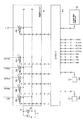
- the hydraulic drive device 400 in the first embodiment has three main hydraulic pumps driven by an engine (not shown), for example, a first hydraulic pump 1 and a second hydraulic pump each composed of a variable displacement hydraulic pump. A pump 2 and a third hydraulic pump 3 are provided. Further, the pilot pump 91 driven by the engine is provided, and the hydraulic pumps 1 to 3 and the hydraulic oil tank 5 for supplying oil to the pilot pump 91 are provided.
- the tilt angle of the first hydraulic pump 1 is controlled by the regulator attached to the first hydraulic pump 1.
- the regulator of the first hydraulic pump 1 includes a flow control command pressure port 1a, a first hydraulic pump self-pressure port 1b, and a second hydraulic pump self-pressure port 1c.
- the tilt angle of the second hydraulic pump 2 is controlled by a regulator attached to the second hydraulic pump 2.
- the regulator of the second hydraulic pump 2 includes a flow control command pressure port 2a, a second hydraulic pump self-pressure port 2b, and a first hydraulic pump self-pressure port 2c.
- the tilt angle of the third hydraulic pump 3 is controlled by a regulator attached to the third hydraulic pump 3.
- the regulator of the third hydraulic pump 3 includes a flow control command pressure port 3a and a third hydraulic pump self-pressure port 3b.
- the discharge line 40 of the first hydraulic pump 1 is connected to the hydraulic oil tank 5 via the center bypass oil passage 41.
- the center bypass oil passage 41 is supplied to the right traveling direction control valve 6 and the bucket cylinder 206a that control the driving of the right traveling motor (not shown) among the pair of traveling motors that drive the traveling body 201 in order from the upstream side.
- a first boom directional control valve 9 for controlling the above is arranged.
- Each supply port of the bucket directional control valve 7, the second arm directional control valve 8, and the first boom directional control valve 9 is a center that connects the right traveling directional control valve 6 and the bucket directional control valve 7. It is connected to a part of the bypass oil passage 41 in parallel via the oil passages 42, 43, oil passages 44, 45, and oil passages 46, 47, respectively. Further, the discharge line 40 is connected to the hydraulic oil tank 5 via the main relief valve 18 in order to protect the circuit from an excessive pressure rise. The discharge line 40 is provided with a pressure sensor (not shown) for detecting the pressure of the first hydraulic pump 1.
- the discharge line 50 of the second hydraulic pump 2 is connected to the hydraulic oil tank 5 via the center bypass oil passage 51, and is also connected to the discharge line 40 of the first hydraulic pump 1 via the merging valve 17.
- the flow of the pressure oil supplied to the second boom directional control valve 10 and the arm cylinder 205a which control the flow of the pressure oil supplied to the boom cylinder 204a, is controlled in this order from the upstream side.
- Direction control valve for the first arm 11 for example, the direction for the first attachment that controls the flow of pressure oil supplied to the first actuator (not shown) that drives the first special attachment such as a small splitting machine provided in place of the bucket 206.
- a control valve 12 and a left traveling direction control valve 13 for controlling the driving of a left traveling motor (not shown) among a pair of traveling motors for driving the traveling body 201 are arranged.
- the supply ports of the second boom directional control valve 10, the first arm directional control valve 11, the first attachment directional control valve 12, and the left traveling directional control valve 13 are the discharge lines 50 of the second hydraulic pump 2.
- a check valve 30 is provided between the connection point with the oil passage 56 and the connection point with the oil passage 58 in the discharge line 50.
- the check valve 30 prevents the hydraulic oil supplied to the discharge line 50 via the merging valve from flowing into the directional control valves 10 to 12 on the upstream side of the traveling left directional control valve 13. Further, the discharge line 50 is connected to the hydraulic oil tank 5 via the main relief valve 19 in order to protect the circuit from an excessive pressure rise.
- the discharge line 50 is provided with a pressure sensor 81 that detects the pressure of the second hydraulic pump 2.
- the meter outport of the directional control valve 11 for the first arm is connected to the hydraulic oil tank 5 via the oil passage 70.
- a variable throttle valve 36 is arranged in the oil passage 70.
- the upstream side of the variable throttle valve 36 is connected to the oil passage 55 via the regeneration valve 35.
- the regeneration valve 35 allows the flow of hydraulic oil from the oil passage 70 (meter outport of the directional control valve 11) to the oil passage 55 (meter import of the directional control valve 11) and blocks the flow in the reverse direction.
- a pressure sensor 87 is provided on the upstream side of the regeneration valve 35, and a pressure sensor 83 is provided on the downstream side of the regeneration valve 35.
- the discharge line 60 of the third hydraulic pump 3 is connected to the hydraulic oil tank 5 via the center bypass oil passage 61.
- a swivel direction control valve 14 that controls the flow of pressure oil supplied to the swivel motor 211, and a third that controls the flow of pressure oil supplied to the boom cylinder 204a.
- a boom directional control valve 15 and a second attachment directional control valve 16 are arranged.
- the directional control valve 16 for the second attachment is provided when a second special attachment equipped with a second actuator is attached in addition to the first special attachment, or when the first special actuator is replaced with the first actuator and the second actuator.
- the supply ports of the turning directional control valve 14, the third boom directional control valve 15, and the second attachment directional control valve 16 are connected to the discharge line 60 of the third hydraulic pump 3, respectively, with oil passages 62 and 63 and oil. It is connected in parallel via roads 64 and 65 and oil passages 66 and 67. Further, the discharge line 60 is connected to the hydraulic oil tank 5 via the main relief valve 20 in order to protect the circuit from an excessive pressure rise.
- the discharge line 60 is provided with a pressure sensor (not shown) that detects the pressure of the third hydraulic pump 3.
- the boom cylinder 204a, arm cylinder 205a, and bucket cylinder 206a are provided with stroke sensors 84, 85, and 86, respectively, for detecting the stroke amount for the purpose of acquiring the operating state of the hydraulic excavator 300.
- the means for acquiring the operating state of the hydraulic excavator 300 is various, such as an inclination sensor, a rotation angle sensor, and an IMU, and is not limited to the stroke sensor described above.
- Oil passages 42 and 43 connected to the bucket directional control valve 7, oil passages 44 and 45 connected to the second arm directional control valve 8, and oil passages 46 connected to the first boom directional control valve 9. , 47 are provided with flow rate control valves 21, 22, 23, respectively, which limit the flow rate of the pressure oil supplied from the first hydraulic pump 1 to the direction control valves 7 to 8 during the combined operation.
- auxiliary flow rate control valves 24 and 25 which limit the flow rate of the pressure oil supplied from the second hydraulic pump 2 to the directional control valves 10 to 12 during the combined operation, 26 are provided respectively.
- Oil passages 62 and 63 connected to the supply port of the turning directional control valve 14, oil passages 64 and 65 connected to the supply port of the third boom directional control valve 15, and the directional control valve 16 for the second attachment.
- Auxiliary flow control valves 27, 28, 29 that limit the flow rate of the pressure oil supplied from the third hydraulic pump 3 to the directional control valves 14 to 16 during the combined operation are provided in the oil passages 66, 67 connected to the supply port. Each is provided.
- the discharge port of the pilot pump 91 is connected to the hydraulic oil tank 5 via the pilot relief valve 92 for generating the primary pilot pressure, and is an electromagnetic proportional valve built in the solenoid valve unit 93 via the oil passage 97. It is connected to one of the input ports of 93a to 93h. The other input port of the electromagnetic proportional valves 93a to 93h is connected to the hydraulic oil tank 5.
- the electromagnetic proportional valves 93a to 93h each reduce the pilot primary pressure in response to a command signal from the controller 94 to generate a pilot command pressure.
- the output port of the electromagnetic proportional valve 93a is connected to the flow control command pressure port 2a of the regulator of the second hydraulic pump 2.
- the output ports of the electromagnetic proportional valves 93b and 93c are connected to the pilot port of the second boom directional control valve 10.
- the output ports of the electromagnetic proportional valves 93d and 93e are connected to the pilot port of the directional control valve 11 for the first arm.
- the output port of the electromagnetic proportional valve 93f is connected to the pilot port of the auxiliary flow control valve 24 (pilot port 32a of the pilot variable throttle 32) via the oil passage 71.
- the output port of the electromagnetic proportional valve 93g is connected to the pilot port of the auxiliary flow control valve 25 (pilot port 34a of the pilot variable throttle 34) via the oil passage 72.
- the output port of the electromagnetic proportional valve 93h is connected to the pilot port of the variable throttle valve 36 via the oil passage 73.
- an electromagnetic proportional valve for the flow control command pressure ports 1a and 3a of the regulators of the first hydraulic pump 1 and the third hydraulic pump 3, and an electromagnetic proportional valve for the right traveling direction control valve 6 are provided.
- the electromagnetic proportional valve for 16 and the electromagnetic proportional valve for auxiliary flow control valves 21 to 23 and 26 to 29 are not shown.
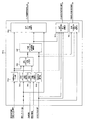
- the auxiliary flow rate control valve 24 is provided on the seat-shaped main valve 31 forming the auxiliary variable throttle and the valve body 31a of the main valve 31, and the control variable throttle 31b that changes the opening amount according to the movement amount of the valve body 31a.
- the pilot variable aperture 32 The housing in which the main valve 31 is built has a first pressure chamber 31c formed at the connection portion between the main valve 31 and the oil passage 52 and a second pressure chamber 31d formed at the connection portion between the main valve 31 and the oil passage 53. And a third pressure chamber 31e formed so as to communicate with each other via the first pressure chamber 31c and the control variable throttle 31b.
- the pilot variable throttle 32 is arranged in the oil passage 68 connecting the third pressure chamber 31e and the oil passage 53.
- the pilot port 32a of the pilot variable throttle 32 is connected to the output port of the electromagnetic proportional valve 93f.
- a pressure sensor 82 is provided in the oil passage 53 connecting the second boom directional control valve 10 and the auxiliary flow rate control valve 24 (main valve 31).
- the hydraulic drive device 400 includes a boom operating lever 95a capable of switching and operating the first boom directional control valve 9, the second boom directional control valve 10, and the third boom directional control valve 15, and the direction for the first arm. It is provided with an arm operation lever 95b capable of switching and operating the control valve 11 and the second arm direction control valve 8.
- the right traveling operation lever for switching the right traveling directional control valve 6, the bucket operating lever for switching the bucket directional control valve 7, and the first attachment directional control valve 12 are switched.
- the operation lever for the second attachment to be switched is not shown.
- the hydraulic drive device 400 includes a controller 94, and the input amounts of the operating levers 95a and 95b, the output values of the pressure sensors 81 to 83 and 87, and the output values of the stroke sensors 84 to 86 are input to the controller 94. Further, the controller 94 outputs a command signal to the solenoid proportional valves 93a to 93h (including the solenoid proportional valve (not shown)) included in the solenoid valve unit 93.
- FIG. 3 is a functional block diagram of the controller 94.
- the controller 94 includes a control activation determination unit 94a, a request actuator flow rate calculation unit 94b, a limited actuator flow rate calculation unit 94c, a regeneration flow rate calculation unit 94d, a target actuator flow rate calculation unit 94e, and a target actuator supply. It has a flow rate calculation unit 94f, a target pump flow rate calculation unit 94g, a target direction control valve opening calculation unit 94h, a target flow control valve opening calculation unit 94i, and a target variable throttle valve opening calculation unit 94j.
- the control activation determination unit 94a determines whether the automatic control function is valid or invalid based on the signal of the automatic control function changeover switch 96.
- the required actuator flow rate calculation unit 94b calculates the required flow rate of the actuator based on the input amounts of the operating levers 95a and 95b.
- the limiting actuator flow rate calculation unit 94c uses the attitude information of the vehicle body 202 or the work device 203 obtained from the signals of the stroke sensors 84 to 86 and the like, and preset design surface information (including the target locus of the registered actuator). Based on this, the actuator flow rate for controlling the vehicle body 202 or the work device 203 so as not to deviate from the set limited area is calculated as the limit flow rate.
- the regeneration flow rate calculation unit 94d calculates the flow rate (regeneration flow rate) passing through the regeneration valve 35 from the output value of the pressure sensor and the preset opening characteristics of the regeneration valve 35.
- the target actuator flow rate calculation unit 94e sets the actuator based on the determination result of the control activation determination unit 94a, the required flow rate of the actuator from the required actuator flow rate calculation unit 94b, and the limited flow rate of the actuator from the limited actuator flow rate calculation unit 94c. Calculate the target flow rate (target actuator flow rate) to be supplied.
- the target actuator supply flow rate calculation unit 94f is a target flow rate supplied to the actuator by the hydraulic pump (target actuator supply flow rate) based on the target actuator flow rate from the target actuator flow rate calculation unit 94e and the regeneration flow rate from the regeneration flow rate calculation unit 94d. Is calculated.
- the target pump flow rate calculation unit 94g is the target flow rate of the hydraulic pumps 1 to 3 based on the determination result of the control activation determination unit 94a, the target actuator supply flow rate from the target actuator supply flow rate calculation unit 94f, and the operation lever input amount. (Target pump flow rate) is calculated, and a command signal (pump flow rate control command signal) corresponding to the target pump flow rate is output.
- the target direction control valve opening calculation unit 94h calculates the target opening amount of the direction control valves 6 to 16 based on the input amount of the operating levers 95a and 95b.
- the target flow control valve opening calculation unit 94i is based on the determination result of the control activation determination unit 94a, the target actuator supply flow rate from the target actuator supply flow rate calculation unit 94f, the operation lever input amount, and the pressure sensor output value.
- the target opening amount of the auxiliary flow control valves 21 to 29 is calculated, and a command signal (flow control valve control command signal) corresponding to the target opening amount is output.
- the target variable throttle valve opening calculation unit 94j is based on the target actuator flow rate from the target actuator flow rate calculation unit 94e, the regeneration flow rate from the regeneration flow rate calculation unit 94d, and the operation lever input amount, and the target opening amount of the variable throttle valve 36. Is calculated, and a command signal (variable throttle valve control command signal) corresponding to the target opening amount is output.
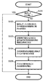
- FIG. 4 is a flowchart showing processing related to the control of the directional control valves 6 to 16 of the controller 94.
- the processing related to the second boom directional control valve 10 will be described. Since the other processes related to the directional control valve are the same as this, the description thereof will be omitted.
- the controller 94 first determines whether or not there is an input of the boom operation lever 95a (step S101). If it is determined in step S101 that there is no input of the boom operation lever 95a (YES), the flow is terminated. If it is determined in step S101 that there is an input (NO) for the boom operating lever 95a, the target direction control valve opening calculation unit 94h of the controller 94 determines that the direction control valve 10 corresponds to the input amount of the boom operating lever 95a. The target opening amount Ams of (step S102) is calculated.
- step S102 the controller 94 outputs a command signal corresponding to the target opening amount Ams to the electromagnetic proportional valves 93b and 93c for the directional control valve 10 (S103), and the pilot of the directional control valve 10 is output to the electromagnetic proportional valves 93b and 93c.
- the command pressure is generated (S104), the direction control valve 10 is opened according to the pilot command pressure (S105), and the flow is terminated.
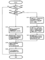
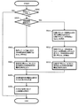
- FIG. 5 is a flowchart showing processing related to the control of the auxiliary flow rate control valves 21 to 29 of the controller 94.
- the processing related to the control of the auxiliary flow rate control valve 24 corresponding to the second boom directional control valve 10 will be described. Since the other processes related to the control of the auxiliary flow control valve are the same as this, the description thereof will be omitted.
- the controller 94 first determines whether or not there is an input of the boom operation lever 95a (step S201). If it is determined in step S201 that there is no input of the boom operation lever 95a (YES), the flow is terminated. If it is determined in step S201 that the boom operation lever 95a is input (NO), it is determined whether or not the automatic control function (machine control) is effective (step S202).
- step S202 If it is determined in step S202 that the automatic control function is invalid (NO), the target flow rate control valve opening calculation unit 94i of the controller 94 uses the auxiliary flow rate control valve 24 (main valve) according to the input amount of the boom operation lever 95a.
- the target opening amount Afcv_M of 31) is calculated (step S203), a command signal corresponding to the target opening amount Afcv_M is output to the electromagnetic proportional valve 93f for the auxiliary flow rate control valve 24 (S204), and the auxiliary flow rate is supplied to the electromagnetic proportional valve 93f.
- the pilot command pressure of the control valve 24 (main valve 31) is generated (S205), the auxiliary flow rate control valve 24 (main valve 31) is opened according to the pilot command pressure (S206), and the flow is terminated.
- the target actuator supply flow rate calculation unit 94f of the controller 94 calculates the target actuator supply flow rate Qact_A by subtracting the regeneration flow rate Qreg from the target actuator flow rate Qref ().
- Step S211 in the target flow rate control valve opening calculation unit 94i of the controller 94, the target of the auxiliary flow rate control valve 24 based on the target actuator supply flow rate Qact_A and the front-rear differential pressure ⁇ Pfcv of the auxiliary flow rate control valve 24 (main valve 31).
- step S212 After calculating the opening amount Afcv_A (step S212), outputting the command signal corresponding to the target opening amount Afcv_A to the electromagnetic proportional valve 93f for the auxiliary flow rate control valve 24 (step S213), and executing the processes of steps S205 and S206. , End the flow.
- FIG. 6 is a flowchart showing processing related to the control of the hydraulic pumps 1 to 3 of the controller 94.
- the processes related to the control of the second hydraulic pump 2 will be described. Since other processes related to the control of the hydraulic pump are the same as this, the description thereof will be omitted.
- the controller 94 first determines whether or not there is an input of the operation levers 95a and 95b (step S301). If it is determined in step S301 that there is no input of the operation levers 95a and 95b (YES), the flow is terminated. If it is determined in step S301 that the operation levers 95a and 95b are input (NO), it is determined whether or not the automatic control function is valid (step S302).
- step S302 If it is determined in step S302 that the automatic control function is invalid (NO), the target pump flow rate calculation unit 94g of the controller 94 calculates the target pump flow rate Qpmp_M of the hydraulic pump 2 according to the input amounts of the operating levers 95a and 95b.
- Step S303 a command signal corresponding to the target pump flow rate Qpmp_M is output to the electromagnetic proportional valve 93a for controlling the flow rate of the hydraulic pump 2 (S304), and the flow control command pressure PiP2 of the hydraulic pump 2 is applied to the electromagnetic proportional valve 93a. It is generated (S305), the inclination of the second hydraulic pump 2 is changed according to the flow control command pressure PiP2 (S306), and the flow is terminated.
- the target actuator supply flow rate calculation unit 94f of the controller 94 calculates the target actuator supply flow rate Qact_Aa, QactAb, ... (Steps S311a, S311b, ). ..
- the target actuator supply flow rate Qact_Aa is the target flow rate supplied by the hydraulic pump 2 to the boom cylinder 204a
- the target actuator supply flow rate Qact_Ab is the target flow rate supplied by the hydraulic pump 2 to the arm cylinder 205a.
- the target pump flow rate calculation unit 94g of the controller 94 calculates the total of the target supply flow rates Qact_Aa, Qact_Ab, ... Of each actuator as the target pump flow rate Qpmp_A (step S312), and the hydraulic pump 2 A command signal corresponding to the target pump flow rate Qpmp_A is output to the electromagnetic proportional valve 93a for flow rate control (S313), the processes of steps S305 and S306 are executed, and then the flow is terminated.
- the target pump flow rate Qpmp_A is appropriately set by the designer, and does not have to be exactly the same as the total target flow rate of each actuator, and the bleed-off flow rate, drain flow rate, and the like may be added.
- FIG. 7 is a flowchart showing a process related to the control of the variable throttle valve 36 of the controller 94.
- the processing related to the control of the variable throttle valve 36 corresponding to the directional control valve 11 for the first arm will be described. Since the processing related to the control of other variable throttle valves (not shown) is the same as this, the description thereof will be omitted.
- the controller 94 first determines whether or not there is an input of the arm operation lever 95b (step S401). If it is determined in step S401 that there is no input of the arm operation lever 95b (YES), the flow is terminated. If it is determined in step S401 that the arm operation lever 95b is input (NO), it is determined whether or not the automatic control function is effective (step S402).
- step S402 If it is determined in step S402 that the automatic control function is invalid (NO), the target variable throttle valve opening calculation unit 94j of the controller 94 determines the target opening amount of the variable throttle valve 36 according to the input value of the arm operation lever 95b.
- Avtv_M is calculated (step S403), a command signal corresponding to the target opening amount Avtv_M is output to the electromagnetic proportional valve 93h for the variable throttle valve 36 (S404), and the pilot command pressure of the variable throttle valve 36 is applied to the electromagnetic proportional valve 93h. It is generated (S405), the variable throttle valve 36 is opened according to the pilot command pressure (S406), and the flow is terminated.
- the regeneration flow rate Qreg changes according to the input amount of the arm operation lever 95b.
- step S402 If it is determined in step S402 that the automatic control function is valid (YES), the target variable throttle valve opening calculation unit 94j of the controller 94 determines whether or not the regenerated flow rate Qreg is larger than the target actuator flow rate QRef (step). S411). If it is determined in step S411 that the regeneration flow rate Qreg is equal to or less than the target actuator flow rate Qref (NO), the processes after step S403 are executed. As a result, as long as the regenerated flow rate Qreg does not exceed the target actuator flow rate Qref, the regenerated flow rate Qreg changes according to the input amount of the arm operating lever 95b.
- step S411 If it is determined in step S411 that the regenerated flow rate Qreg is larger than the target actuator flow rate Qref (YES), the target variable throttle valve opening calculation unit 94j of the controller 94 is larger than the current opening amount Avtv_Avef of the variable throttle valve 36.
- step S412 After calculating the target opening amount Avtv_A (step S412), outputting the command signal corresponding to the target opening amount Avtv_A to the electromagnetic proportional valve 93h for the variable throttle valve 36 (S413), and executing the processes of steps S405 and S405, End the flow.
- the regeneration flow rate Qreg is limited to the target actuator flow rate Qref or less.
- the electromagnetic proportional valves 93d and 93e generate pilot command pressures PiAm1U and PiAm1D in response to the command signal, and control the opening amount of the directional control valve 11 for the first arm.
- the auxiliary flow rate control valve controller 94 calculates the target opening amount Afcv_M of the auxiliary flow rate control valve 25 (main valve 33) according to the input amount of the arm operation lever 95b, and electromagnetically transmits a command signal corresponding to the target opening amount Afcv_M. Output to the proportional valve 93g.
- the electromagnetic proportional valve 93g generates a pilot command pressure in response to a command signal, and controls the opening amount of the auxiliary flow rate control valve 25 (main valve 33).
- the auxiliary flow rate control valve 25 (main valve 33) is controlled so as to have the maximum opening amount (the auxiliary flow rate control valve 25 (main valve 33) is fully opened).
- the hydraulic pump controller 94 calculates the target flow rate Qpmp_M of the second hydraulic pump 2 according to the input amount of the arm operation lever 95b, and outputs a command signal corresponding to the target flow rate Qmpmp_M to the electromagnetic proportional valve 93a.
- the electromagnetic proportional valve 93a generates a flow rate control command pressure PiP2 in response to a command signal, and controls the flow rate of the second hydraulic pump 2.
- the variable throttle valve controller 94 calculates the target opening amount Avtv_M of the variable throttle valve 36 according to the input amount of the arm operation lever 95b, and outputs a command signal corresponding to the target opening amount Avtv_M to the electromagnetic proportional valve 93h.
- the electromagnetic proportional valve 93h generates a pilot command pressure in response to a command signal and controls the opening amount of the variable throttle valve 36.
- the directional control valve controller 94 calculates the target opening amount Ams of the first arm directional control valve 11 according to the input amount of the arm operating lever 95b, and sends a command signal corresponding to the target opening amount Ams to the electromagnetic proportional valve 93d. , 93e is output.
- the electromagnetic proportional valves 93d and 93e generate pilot command pressures PiAm1U and PiAm1D in response to the command signal, and control the opening amount of the directional control valve 11 for the first arm.
- the auxiliary flow rate control valve controller 94 calculates the target actuator flow rate Qref and the regeneration flow rate Qreg based on the input amount of the arm operation lever 95b, the attitude information of the vehicle body 202 or the work device 203, the design surface information, and the pressure sensor output value. Then, the target actuator supply flow rate Qact_A is calculated by subtracting the regeneration flow rate Qreg from the target actuator flow rate Qref, and the auxiliary flow rate control is performed based on the target actuator supply flow rate Qact_A and the front-rear differential pressure ⁇ Pfcv of the auxiliary flow rate control valve 25 (main valve 33).
- the target opening amount Afcv_A of the valve 25 (main valve 33) is calculated, and a command signal corresponding to the target opening amount Afcv_A is output to the electromagnetic proportional valve 93 g.
- the electromagnetic proportional valve 93g generates a pilot command pressure in response to a command signal, and controls the opening amount of the auxiliary flow rate control valve 25 (main valve 33).
- the hydraulic pump controller 94 calculates the target pump flow rate Qpmp_A by summing the target supply flow rate Qact_A of each actuator, and outputs a command signal corresponding to the target pump flow rate Qpmp_A to the electromagnetic proportional valve 93a.
- the electromagnetic proportional valve 93a generates a flow rate control command pressure Pipe 2 in response to a command signal, and controls the flow rate of the second hydraulic pump 2. Since this operation is an independent operation of the arm cylinder 205a, the target pump flow rate Qpmp_A is equal to the target supply flow rate Qact_A of the arm cylinder 205a.
- the variable throttle valve controller 94 determines whether or not the regenerated flow rate Qreg is larger than the target actuator flow rate Qref. If the determination result is YES, the target opening amount Avtv_M of the variable throttle valve 36 according to the input amount of the arm operating lever 95b is calculated, and the command signal corresponding to the target opening amount Avtv_M is output to the electromagnetic proportional valve 93h.
- the target opening amount Avtv_A larger than the current opening amount Avtv_Abef of the variable throttle valve 36 is calculated, and the command signal corresponding to the target opening amount Avtv_A is output to the electromagnetic proportional valve 93h.
- the electromagnetic proportional valve 93h generates a pilot command pressure in response to a command signal and controls the opening amount of the variable throttle valve 36.
- the hydraulic pumps 1 to 3 that suck the hydraulic oil from the hydraulic oil tank 5 and supply it to the actuators 204a, 205a, 206a, 211 and the discharge lines 40, 50, 60 of the hydraulic pumps 1 to 3 are connected in parallel. Instructs the operation of the flow control valves 6 to 16, 21 to 29 for controlling the flow of the pressure oil supplied from the hydraulic pumps 1 to 3 to the actuators 204a, 205a, 206a, 211 and the actuators 204a, 205a, 206a, 211.
- the controller 94 includes a regeneration valve 35 arranged in an oil passage connecting the meter out port and the meter import, and pressure sensors 87 and 83 for detecting the front-rear differential pressure of the regeneration valve 35, and the controller 94 has operating levers 95a and 95b.
- the target actuator flow rate Qref which is the target flow rate of the actuators 204a, 205a, 206a, 211, is calculated based on the operation instruction amount from, and the regeneration flow rate Qreg, which is the passing flow rate of the regeneration valve 35, is calculated based on the front-rear differential pressure of the regeneration valve 35.
- the target actuator supply flow rate Qact_A is calculated by subtracting the regeneration flow rate Qreg from the target actuator flow rate Qref, the target flow control valve opening amount Afcv_A is calculated based on the target actuator supply flow rate Qact_A, and the total of the target actuator supply flow rate Qact_A.
- the target pump flow rate Qpmp_A as described above is calculated, the flow rate control valves 21 to 29 are controlled according to the target flow control valve opening amount Afcv_A, and the hydraulic pumps 1 to 3 are controlled according to the target pump flow rate Qpmp_A.
- the flow control valves 6 to 16 and 21 to 29 are a direction control valve 6 to 16 for controlling the direction of the pressure oil supplied from the hydraulic pumps 1 to 3 to the actuators 204a, 205a, 206a and 211, and the hydraulic pump 1 It has auxiliary flow rate control valves 21 to 29 that limit the flow rate of the pressure oil supplied to the meter import of the direction control valves 6 to 16 from 3 to 3, and the regeneration valve 35 has a meter out port of the direction control valve 11 and a meter. It is located in the oil channel connecting the import.
- the sum of the target flow rate (target actuator supply flow rate Qact_A) supplied to the actuator by the hydraulic pumps 1 to 3 and the regeneration flow rate Qreg of the actuator is the target flow rate of the actuator (target actuator flow rate).
- the flow control valves 21 to 29 and the hydraulic pumps 1 to 3 are controlled so as to be equal to Qref).
- the work machine 300 includes a variable throttle valve 36 provided in an oil passage 70 connecting the meter out port of the flow rate control valve 11 and the hydraulic oil tank 5, and the controller 94 uses the regenerated flow rate Qreg.
- the opening amount of the variable throttle valve 36 is increased until the regenerated flow rate Qreg becomes equal to or less than the target actuator flow rate Qref. This makes it possible to maximize the regeneration flow rate Qreg while maintaining the supply flow rate to the actuator at the target flow rate Qact_A.
- the work machine 300 includes an automatic control function changeover switch 96 for instructing activation or invalidation of the automatic control function of the vehicle body 202 or the work device 203, and the controller 94 is an automatic control function changeover switch 96.
- the target flow rate control valve opening amount Afcv_M and the target pump flow rate Qpmp_M are calculated based on the operation instruction amounts from the operating levers 95a and 95b.
- FIGS. 8A and 8B are circuit diagrams of a hydraulic drive device according to a second embodiment of the present invention.
- (1) Configuration The configuration of the hydraulic drive system 400A in this embodiment is almost the same as that of the hydraulic drive system 400 (shown in FIGS. 2A and 2B) in the first embodiment, but is different in the following points.
- the hydraulic drive device 400A in the present embodiment includes check valves 101 to 109 for preventing backflow from the actuator side to the discharge lines 40, 50, 60 instead of the auxiliary flow control valves 21 to 29 in the first embodiment. ing.
- the regeneration valve 35 in this embodiment is arranged inside the spool of the first arm directional control valve 11, and the first arm directional control valve 11 is provided with regeneration ports 121 and 122.
- An oil passage 111 branched from an oil passage 70 connected to the meter out port of the directional control valve 11 for the first arm is connected to the regeneration port 121.
- An oil passage 112 branched from an oil passage 114 connecting the first arm directional control valve 11 and the bottom side of the arm cylinder 205a is connected to the regeneration port 122.
- the oil passage 111 is connected to the upstream side of the regeneration valve 35, and the oil passage 112 is connected to the downstream side of the regeneration valve 35. Be connected.
- the hydraulic oil discharged from the rod side of the arm cylinder 205a is regenerated to the bottom side.
- Pressure sensors 117 and 118 are provided in the oil passages 113 and 114 connecting the directional control valve 11 for the first arm and the arm cylinder 205a, respectively.
- FIG. 9 is a functional block diagram of the controller 94A in this embodiment.
- the controller 94A in the present embodiment replaces the target direction control valve opening calculation unit 94h and the target flow rate control valve opening calculation unit 94i (shown in FIG. 3) in the first embodiment with the target direction control valve opening. It has a calculation unit 94k.
- the target direction control valve opening calculation unit 94k is based on the determination result from the control activation determination unit 94a, the target actuator supply flow rate from the target actuator supply flow rate calculation unit 94f, the operation lever input amount, and the pressure sensor output value. Calculate the target opening amount of the direction control valve.
- FIG. 10 is a flowchart showing processing related to the control of the directional control valves 6 to 16 of the controller 94A.
- processing related to the control of the second boom directional control valve 10 will be described. Since the other processes related to the control of the directional control valve are the same as this, the description thereof will be omitted.
- the controller 94A first determines whether or not there is an input of the boom operation lever 95a (step S501). If it is determined in step S501 that there is no input of the boom operation lever 95a (YES), the flow is terminated. When it is determined in step S501 that the boom operation lever 95a is input (NO), it is determined whether or not the automatic control function (machine control) is effective (step S502).
- step S502 If it is determined in step S502 that the automatic control function is invalid (NO), the target direction control valve opening calculation unit 94k of the controller 94A determines the target opening amount of the direction control valve 10 according to the input amount of the boom operation lever 95a.
- Ams_M is calculated (step S503), a command signal corresponding to the target opening amount Ams_M is output to the electromagnetic proportional valves 93b and 93c for the directional control valve 10 (S504), and the directional control valve 10 is output to the electromagnetic proportional valves 93b and 93c.
- a pilot command pressure is generated (S505), the direction control valve 10 is opened according to the pilot command pressure (S506), and the flow is terminated.
- step S502 If it is determined in step S502 that the automatic control function is valid (YES), the target actuator supply flow rate calculation unit 94f of the controller 94A calculates the target actuator supply flow rate Qact_A by subtracting the regeneration flow rate Qreg from the target actuator flow rate Qref (). In step S511), the target direction control valve opening calculation unit 94k of the controller 94A calculates the target opening amount Ams_A of the direction control valve 10 based on the target actuator supply flow rate Qact_A and the front-rear differential pressure ⁇ Pms of the direction control valve 10.
- Step S512 a command signal corresponding to the target opening amount Ams_A is output to the electromagnetic proportional valves 93b and 93c for the directional control valve 10 (step S513), the processes of steps S505 and S506 are executed, and then the flow is terminated. do.
- (2) Operation The operation of the hydraulic drive system 400A in the second embodiment will be described by taking up a part related to the second hydraulic pump 2. Since the operation of the parts related to other hydraulic pumps is the same as this, the description thereof will be omitted. (2-1) Operation in the state where the automatic control function is disabled The operation of each device when the arm operation lever 95b is operated in the state where the automatic control function is disabled will be described.
- the directional control valve controller 94A calculates the target opening amount Ams_M of the first arm directional control valve 11 according to the input amount of the arm operating lever 95b, and sends a command signal corresponding to the target opening amount Ams_M to the electromagnetic proportional valve 93d. , 93e is output.
- the electromagnetic proportional valves 93d and 93e generate pilot command pressures PiAm1U and PiAm1D in response to the command signal, and control the opening amount of the directional control valve 11 for the first arm. -Since it is the same as the first embodiment of the hydraulic pump, the description thereof will be omitted. -Variable throttle valve Since it is the same as that of the first embodiment, the description thereof will be omitted.
- the direction control valve controller 94A calculates the target actuator flow rate Qref and the regeneration flow rate Qreg based on the input amount of the arm operation lever 95b, the attitude information of the vehicle body 202 or the work device 203, the design surface information, and the pressure sensor output value.
- the target actuator supply flow rate Qact_A is calculated by subtracting the regeneration flow rate Qreg from the target actuator flow rate Qref, and the target opening amount Ams_A of the direction control valve 11 is calculated based on the target actuator supply flow rate Qact_A and the front-rear differential pressure ⁇ Pms of the direction control valve 11.
- the command signal calculated and corresponding to the target opening amount Ams_A is output to the electromagnetic proportional valves 93d and 93e.
- the electromagnetic proportional valves 93d and 93e generate pilot command pressures PiAm1U and PiAm1D in response to the command signal, and control the opening amount of the directional control valve 11.
- the flow control valves 6 to 16 for controlling the flow of the pressure oil supplied from the hydraulic pumps 1 to 3 to the actuators 204a, 205a, 206a and 211 are from the hydraulic pumps 1 to 3. It is a directional control valve that controls the direction and flow rate of the pressure oil supplied to the actuators 204a, 205a, 206a, 211, and the regeneration valve 115 is arranged inside the spool of the directional control valve 11.
- the second embodiment configured as described above, it is possible to increase the operating speed of the actuator by the reproduction function while ensuring the position control accuracy of the actuator with a simpler configuration than the first embodiment. It will be possible. As a result, the work efficiency of the work machine 100 can be improved while suppressing the cost.
- the present invention is not limited to the above-mentioned examples, and includes various modifications.
- the above-described embodiment has been described in detail in order to explain the present invention in an easy-to-understand manner, and is not necessarily limited to those having all the described configurations. It is also possible to add a part of the configuration of another embodiment to the configuration of one embodiment, delete a part of the configuration of one embodiment, or replace it with a part of another embodiment. It is possible.
- Direction control valve for bucket (flow control valve) ), 8 ... 2nd arm directional control valve (flow control valve), 9 ... 1st boom directional control valve (flow control valve), 10 ... 2nd boom directional control valve (flow control valve), 11 ... 1-arm directional control valve (flow control valve), 12 ... directional control valve for 1st attachment (flow control valve), 13 ... left-traveling directional control valve (flow control valve), 14 ... directional control valve for turning (flow rate) Control valve), 15 ... 3rd boom directional control valve (flow control valve), 16 ... 2nd attachment directional control valve (flow control valve), 17 ... merging valve, 18-20 ... main relief valve, 21-29 ... Auxiliary flow control valve (flow control valve), 30 ...
- Target flow control valve opening calculation unit 94j ... Target variable throttle valve opening calculation unit, 94k ... Target direction control valve opening calculation unit, 95a ... Boom operation lever, 95b ... Arm operation lever, 96 ... Automatic control Function changeover switch, 97 ... oil passage, 101-109 ... check valve, 111-114 ... oil passage, 117-120 ... pressure sensor, 121, 122 ... regeneration port, 201 ... traveling body, 202 ... swivel body (body), 203 ... Working device, 204 ... Boom, 204a ... Boom cylinder (actuator), 205 ... Arm, 205a ... Arm cylinder (actuator), 206 ... Bucket, 206a ...
- Bucket cylinder (actuator), 207 ... Driver's cab, 208 ... Machine room , 209 ... counter weight, 210 ... control valve, 211 ... swivel motor (actuator), 300 ... hydraulic excavator (working machine), 400, 400A ... hydraulic drive device.
Landscapes
- Engineering & Computer Science (AREA)
- General Engineering & Computer Science (AREA)
- Mining & Mineral Resources (AREA)
- Civil Engineering (AREA)
- Structural Engineering (AREA)
- Mechanical Engineering (AREA)
- Physics & Mathematics (AREA)
- Fluid Mechanics (AREA)
- Operation Control Of Excavators (AREA)
- Fluid-Pressure Circuits (AREA)
Abstract
Description
(1)構成
第1の実施例における油圧駆動装置400は、エンジン(図示せず)によって駆動される3つの主油圧ポンプ、例えばそれぞれ可変容量形油圧ポンプからなる第1油圧ポンプ1、第2油圧ポンプ2、および第3油圧ポンプ3を備えている。また、エンジンによって駆動されるパイロットポンプ91を備えると共に、油圧ポンプ1~3およびパイロットポンプ91に油を供給する作動油タンク5を備えている。
(2)動作
油圧駆動装置400の動作について、第2油圧ポンプ2に関わる部分を取り上げて説明する。他の油圧ポンプに関わる部分の動作についてはこれと同様であるため、説明は省略する。
(2-1)自動制御機能が無効な状態での操作
自動制御機能が無効な状態でアーム用操作レバー95bが操作された場合の各機器の動作を説明する。
・方向制御弁
コントローラ94は、アーム用操作レバー95bの入力量に応じた第1アーム用方向制御弁11の目標開口量Amsを算出し、目標開口量Amsに応じた指令信号を電磁比例弁93d,93eへ出力する。電磁比例弁93d,93eは、指令信号に応じてパイロット指令圧PiAm1U,PiAm1Dを生成し、第1アーム用方向制御弁11の開口量を制御する。
・補助流量制御弁
コントローラ94は、アーム用操作レバー95bの入力量に応じた補助流量制御弁25(主弁33)の目標開口量Afcv_Mを算出し、目標開口量Afcv_Mに応じた指令信号を電磁比例弁93gへ出力する。電磁比例弁93gは、指令信号に応じてパイロット指令圧を生成し、補助流量制御弁25(主弁33)の開口量を制御する。本動作例では、補助流量制御弁25(主弁33)の開口量が最大となる(補助流量制御弁25(主弁33)が全開となる)ように制御する。
・油圧ポンプ
コントローラ94は、アーム用操作レバー95bの入力量に応じた第2油圧ポンプ2の目標流量Qpmp_Mを算出し、目標流量Qpmp_Mに応じた指令信号を電磁比例弁93aへ出力する。電磁比例弁93aは、指令信号に応じて流量制御指令圧PiP2を生成し、第2油圧ポンプ2の流量を制御する。
・可変絞り弁
コントローラ94は、アーム用操作レバー95bの入力量に応じた可変絞り弁36の目標開口量Avtv_Mを算出し、目標開口量Avtv_Mに応じた指令信号を電磁比例弁93hへ出力する。電磁比例弁93hは、指令信号に応じてパイロット指令圧を生成し、可変絞り弁36の開口量を制御する。
(2-2)自動制御機能が有効な状態での操作
自動制御機能が有効な状態でアーム用操作レバー95bが操作された場合の各機器の動作を説明する。
・方向制御弁
コントローラ94は、アーム用操作レバー95bの入力量に応じた第1アーム用方向制御弁11の目標開口量Amsを算出し、目標開口量Amsに応じた指令信号を電磁比例弁93d,93eへ出力する。電磁比例弁93d,93eは、指令信号に応じてパイロット指令圧PiAm1U,PiAm1Dを生成し、第1アーム用方向制御弁11の開口量を制御する。
・補助流量制御弁
コントローラ94は、アーム用操作レバー95bの入力量、車体202または作業装置203の姿勢情報、設計面情報、および圧力センサ出力値に基づいて目標アクチュエータ流量Qrefと再生流量Qregを算出し、目標アクチュエータ流量Qrefから再生流量Qregを引いて目標アクチュエータ供給流量Qact_Aを算出し、目標アクチュエータ供給流量Qact_Aと補助流量制御弁25(主弁33)の前後差圧ΔPfcvとに基づいて補助流量制御弁25(主弁33)の目標開口量Afcv_Aを算出し、目標開口量Afcv_Aに応じた指令信号を電磁比例弁93gへ出力する。電磁比例弁93gは、指令信号に応じてパイロット指令圧を生成し、補助流量制御弁25(主弁33)の開口量を制御する。
・油圧ポンプ
コントローラ94は、各アクチュエータの目標供給流量Qact_Aを合計して目標ポンプ流量Qpmp_Aを算出し、目標ポンプ流量Qpmp_Aに応じた指令信号を電磁比例弁93aへ出力する。電磁比例弁93aは、指令信号に応じて流量制御指令圧Pip2を生成し、第2油圧ポンプ2の流量を制御する。なお、本動作はアームシリンダ205aの単独動作であるため、目標ポンプ流量Qpmp_Aはアームシリンダ205aの目標供給流量Qact_Aと等しくなる。
・可変絞り弁
コントローラ94は、再生流量Qregが目標アクチュエータ流量Qrefよりも大きいか否かを判定する。判定結果がYESの場合は、アーム用操作レバー95bの入力量に応じた可変絞り弁36の目標開口量Avtv_Mを算出し、目標開口量Avtv_Mに応じた指令信号を電磁比例弁93hへ出力する。判定結果がNOの場合は、可変絞り弁36の現在の開口量Avtv_Abefよりも大きい目標開口量Avtv_Aを算出し、目標開口量Avtv_Aに応じた指令信号を電磁比例弁93hへ出力する。電磁比例弁93hは、指令信号に応じてパイロット指令圧を生成し、可変絞り弁36の開口量を制御する。
(3)効果
本実施の形態では、車体202と、車体202に取り付けられた作業装置203と、車体202または作業装置203を駆動するアクチュエータ204a,205a,206a,211と、作動油タンク5と、作動油タンク5から作動油を吸入し、アクチュエータ204a,205a,206a,211へ供給する油圧ポンプ1~3と、油圧ポンプ1~3の吐出ライン40,50,60にパラレルに接続されており、油圧ポンプ1~3からアクチュエータ204a,205a,206a,211に供給される圧油の流れを制御する流量制御弁6~16,21~29と、アクチュエータ204a,205a,206a,211の動作を指示するための操作レバー95a,95bと、操作レバー95a,95bからの動作指示量に応じて流量制御弁6~16,21~29を制御するコントローラ94とを備えた作業機械300において、流量制御弁11のメータアウトポートとメータインポートとを接続する油路に配置された再生弁35と、再生弁35の前後差圧を検出する圧力センサ87,83とを備え、コントローラ94は、操作レバー95a,95bからの動作指示量に基づいてアクチュエータ204a,205a,206a,211の目標流量である目標アクチュエータ流量Qrefを算出し、再生弁35の前後差圧に基づいて再生弁35の通過流量である再生流量Qregを算出し、目標アクチュエータ流量Qrefから再生流量Qregを引いて目標アクチュエータ供給流量Qact_Aを算出し、目標アクチュエータ供給流量Qact_Aに基づいて目標流量制御弁開口量Afcv_Aを算出し、目標アクチュエータ供給流量Qact_Aの合計以上となる目標ポンプ流量Qpmp_Aを算出し、目標流量制御弁開口量Afcv_Aに応じて流量制御弁21~29を制御し、目標ポンプ流量Qpmp_Aに応じて油圧ポンプ1~3を制御する。
(1)構成
本実施例における油圧駆動装置400Aの構成は、第1の実施例における油圧駆動装置400(図2Aおよび図2Bに示す)とほぼ同様であるが、以下の点で異なる。
(2)動作
第2の実施例における油圧駆動装置400Aの動作について、第2油圧ポンプ2に関わる部分を取り上げて説明する。他の油圧ポンプに関わる部分の動作についてはこれと同様であるため、説明は省略する。
(2-1)自動制御機能が無効な状態での操作
自動制御機能が無効な状態でアーム用操作レバー95bが操作された場合の各機器の動作を説明する。
・方向制御弁
コントローラ94Aは、アーム用操作レバー95bの入力量に応じた第1アーム用方向制御弁11の目標開口量Ams_Mを算出し、目標開口量Ams_Mに応じた指令信号を電磁比例弁93d,93eへ出力する。電磁比例弁93d,93eは、指令信号に応じてパイロット指令圧PiAm1U,PiAm1Dを生成し、第1アーム用方向制御弁11の開口量を制御する。
・油圧ポンプ
第1の実施例と同様であるため、説明は省略する。
・可変絞り弁
第1の実施例と同様であるため、説明は省略する。
(2-2)自動制御機能が有効な状態での操作
自動制御機能が有効な状態でアーム用操作レバー95bが操作された場合の各機器の動作を説明する。
・方向制御弁
コントローラ94Aは、アーム用操作レバー95bの入力量、車体202または作業装置203の姿勢情報、設計面情報、および圧力センサ出力値に基づいて目標アクチュエータ流量Qrefと再生流量Qregを算出し、目標アクチュエータ流量Qrefから再生流量Qregを引いて目標アクチュエータ供給流量Qact_Aを算出し、目標アクチュエータ供給流量Qact_Aと方向制御弁11の前後差圧ΔPmsとに基づいて方向制御弁11の目標開口量Ams_Aを算出し、目標開口量Ams_A応じた指令信号を電磁比例弁93d,93eへ出力する。電磁比例弁93d,93eは、指令信号に応じてパイロット指令圧PiAm1U,PiAm1Dを生成し、方向制御弁11の開口量を制御する。
・油圧ポンプ
第1の実施例と同様であるため、説明は省略する。
・可変絞り弁
第1の実施例と同様であるため、説明は省略する。
(3)効果
第2の実施例では、油圧ポンプ1~3からアクチュエータ204a,205a,206a,211に供給される圧油の流れを制御する流量制御弁6~16は、油圧ポンプ1~3からアクチュエータ204a,205a,206a,211に供給される圧油の方向および流量を制御する方向制御弁であり、再生弁115は、方向制御弁11のスプールの内部に配置されている。
Claims (5)
- 車体と、
前記車体に取り付けられた作業装置と、
前記車体または前記作業装置を駆動するアクチュエータと、
作動油タンクと、
前記作動油タンクから作動油を吸入し、前記アクチュエータへ供給する油圧ポンプと、
前記油圧ポンプの吐出ラインにパラレルに接続されており、前記油圧ポンプから前記アクチュエータに供給される圧油の流れを制御する流量制御弁と、
前記アクチュエータの動作を指示するための操作レバーと、
前記操作レバーからの動作指示量に応じて前記流量制御弁を制御するコントローラとを備えた作業機械において、
前記流量制御弁のメータアウトポートとメータインポートとを接続する油路に配置された再生弁と、
前記再生弁の前後差圧を検出する圧力センサとを備え、
前記コントローラは、
前記操作レバーからの動作指示量に基づいて前記アクチュエータの目標流量である目標アクチュエータ流量を算出し、
前記再生弁の前後差圧に基づいて前記再生弁の通過流量である再生流量を算出し、
前記目標アクチュエータ流量から前記再生流量を引いて目標アクチュエータ供給流量を算出し、
前記目標アクチュエータ供給流量に基づいて目標流量制御弁開口量を算出し、
前記目標アクチュエータ供給流量の合計以上となる目標ポンプ流量を算出し、
前記目標流量制御弁開口量に応じて前記流量制御弁を制御し、
前記目標ポンプ流量に応じて前記油圧ポンプを制御する
ことを特徴とする作業機械。 - 請求項1に記載の作業機械において、
前記流量制御弁は、前記油圧ポンプから前記アクチュエータに供給される圧油の方向を制御する方向制御弁と、前記油圧ポンプから前記方向制御弁のメータインポートに供給される圧油の流量を制限する補助流量制御弁とを有し、
前記再生弁は、前記方向制御弁のメータアウトポートとメータインポートとを接続する油路に配置されている
ことを特徴とする建設機械。 - 請求項1に記載の作業機械において、
前記流量制御弁は、前記油圧ポンプから前記アクチュエータに供給される圧油の方向および流量を制御する方向制御弁であり、
前記再生弁は、前記方向制御弁のスプールの内部に配置されている
ことを特徴とする建設機械。 - 請求項1に記載の作業機械において、
前記流量制御弁のメータアウトポートと前記作動油タンクとを接続する油路に設けられた可変絞り弁を備え、
前記コントローラは、前記再生流量が前記目標アクチュエータ流量を上回った場合に、前記再生流量が前記目標アクチュエータ流量以下となるまで前記可変絞り弁の開口量を増加させる
ことを特徴とする建設機械。 - 請求項1に記載の作業機械において、
前記車体または前記作業装置の自動制御機能の有効化または無効化を指示する自動制御機能切替スイッチを備え、
前記コントローラは、前記自動制御機能切替スイッチにより前記自動制御機能の無効化が指示された場合は、前記操作レバーからの動作指示量に基づいて前記目標流量制御弁開口量および前記目標ポンプ流量を算出する
ことを特徴とする建設機械。
Priority Applications (5)
| Application Number | Priority Date | Filing Date | Title |
|---|---|---|---|
| CN202180020426.1A CN115279976B (zh) | 2020-04-02 | 2021-03-31 | 作业机械 |
| EP21780963.1A EP4101991B1 (en) | 2020-04-02 | 2021-03-31 | Working machine |
| KR1020227031440A KR102706842B1 (ko) | 2020-04-02 | 2021-03-31 | 작업 기계 |
| US17/910,953 US12371873B2 (en) | 2020-04-02 | 2021-03-31 | Work machine |
| JP2022512656A JP7232964B2 (ja) | 2020-04-02 | 2021-03-31 | 作業機械 |
Applications Claiming Priority (2)
| Application Number | Priority Date | Filing Date | Title |
|---|---|---|---|
| JP2020-066997 | 2020-04-02 | ||
| JP2020066997 | 2020-04-02 |
Publications (1)
| Publication Number | Publication Date |
|---|---|
| WO2021201158A1 true WO2021201158A1 (ja) | 2021-10-07 |
Family
ID=77929100
Family Applications (1)
| Application Number | Title | Priority Date | Filing Date |
|---|---|---|---|
| PCT/JP2021/013993 Ceased WO2021201158A1 (ja) | 2020-04-02 | 2021-03-31 | 作業機械 |
Country Status (6)
| Country | Link |
|---|---|
| US (1) | US12371873B2 (ja) |
| EP (1) | EP4101991B1 (ja) |
| JP (1) | JP7232964B2 (ja) |
| KR (1) | KR102706842B1 (ja) |
| CN (1) | CN115279976B (ja) |
| WO (1) | WO2021201158A1 (ja) |
Cited By (2)
| Publication number | Priority date | Publication date | Assignee | Title |
|---|---|---|---|---|
| US20220333348A1 (en) * | 2020-03-30 | 2022-10-20 | Hitachi Construction Machinery Co., Ltd. | Work Machine |
| JP2023150467A (ja) * | 2022-03-31 | 2023-10-16 | 日立建機株式会社 | 作業機械 |
Citations (5)
| Publication number | Priority date | Publication date | Assignee | Title |
|---|---|---|---|---|
| JPS594680B2 (ja) | 1980-02-29 | 1984-01-31 | 株式会社東芝 | 原子炉隔離弁制御装置 |
| JPH11101202A (ja) * | 1997-09-27 | 1999-04-13 | Yutani Heavy Ind Ltd | 油圧ショベルの制御装置及び制御方法 |
| JP3056254B2 (ja) | 1994-04-28 | 2000-06-26 | 日立建機株式会社 | 建設機械の領域制限掘削制御装置 |
| JP2018003516A (ja) | 2016-07-06 | 2018-01-11 | 日立建機株式会社 | 作業機械 |
| WO2018235779A1 (ja) * | 2017-06-21 | 2018-12-27 | 住友重機械工業株式会社 | ショベル |
Family Cites Families (9)
| Publication number | Priority date | Publication date | Assignee | Title |
|---|---|---|---|---|
| JP3594680B2 (ja) | 1995-02-13 | 2004-12-02 | 日立建機株式会社 | 油圧機械の油圧再生装置 |
| JPH11256623A (ja) * | 1998-03-13 | 1999-09-21 | Komatsu Ltd | 建設機械の油圧制御装置およびその油圧制御方法 |
| JP3056254U (ja) | 1998-07-28 | 1999-02-12 | 泰範 中西 | 木工ボンド及びマヨネーズの抽出容器 |
| JP2001302183A (ja) * | 2000-04-14 | 2001-10-31 | Hitachi Constr Mach Co Ltd | 油圧速度制御装置、フック過巻防止装置および干渉防止装置 |
| JP5089973B2 (ja) * | 2006-07-21 | 2012-12-05 | キャタピラー エス エー アール エル | 作業機械のポンプ制御方法 |
| JP4844363B2 (ja) * | 2006-11-28 | 2011-12-28 | コベルコ建機株式会社 | 油圧駆動装置及びこれを備えた作業機械 |
| JP6605242B2 (ja) * | 2015-07-08 | 2019-11-13 | 株式会社神戸製鋼所 | 作業機械の油圧駆動装置 |
| KR102241944B1 (ko) * | 2017-12-26 | 2021-04-19 | 히다치 겡키 가부시키 가이샤 | 작업 기계 |
| JP7473337B2 (ja) * | 2019-12-27 | 2024-04-23 | 株式会社小松製作所 | 作業機械の制御システム、作業機械、及び作業機械の制御方法 |
-
2021
- 2021-03-31 WO PCT/JP2021/013993 patent/WO2021201158A1/ja not_active Ceased
- 2021-03-31 KR KR1020227031440A patent/KR102706842B1/ko active Active
- 2021-03-31 US US17/910,953 patent/US12371873B2/en active Active
- 2021-03-31 EP EP21780963.1A patent/EP4101991B1/en active Active
- 2021-03-31 CN CN202180020426.1A patent/CN115279976B/zh active Active
- 2021-03-31 JP JP2022512656A patent/JP7232964B2/ja active Active
Patent Citations (5)
| Publication number | Priority date | Publication date | Assignee | Title |
|---|---|---|---|---|
| JPS594680B2 (ja) | 1980-02-29 | 1984-01-31 | 株式会社東芝 | 原子炉隔離弁制御装置 |
| JP3056254B2 (ja) | 1994-04-28 | 2000-06-26 | 日立建機株式会社 | 建設機械の領域制限掘削制御装置 |
| JPH11101202A (ja) * | 1997-09-27 | 1999-04-13 | Yutani Heavy Ind Ltd | 油圧ショベルの制御装置及び制御方法 |
| JP2018003516A (ja) | 2016-07-06 | 2018-01-11 | 日立建機株式会社 | 作業機械 |
| WO2018235779A1 (ja) * | 2017-06-21 | 2018-12-27 | 住友重機械工業株式会社 | ショベル |
Non-Patent Citations (1)
| Title |
|---|
| See also references of EP4101991A4 |
Cited By (4)
| Publication number | Priority date | Publication date | Assignee | Title |
|---|---|---|---|---|
| US20220333348A1 (en) * | 2020-03-30 | 2022-10-20 | Hitachi Construction Machinery Co., Ltd. | Work Machine |
| US11739502B2 (en) * | 2020-03-30 | 2023-08-29 | Hitachi Construction Machinery Co., Ltd. | Work machine |
| JP2023150467A (ja) * | 2022-03-31 | 2023-10-16 | 日立建機株式会社 | 作業機械 |
| JP7705822B2 (ja) | 2022-03-31 | 2025-07-10 | 日立建機株式会社 | 作業機械 |
Also Published As
| Publication number | Publication date |
|---|---|
| US12371873B2 (en) | 2025-07-29 |
| EP4101991B1 (en) | 2025-09-17 |
| CN115279976A (zh) | 2022-11-01 |
| KR102706842B1 (ko) | 2024-09-19 |
| EP4101991A4 (en) | 2024-04-24 |
| US20230167622A1 (en) | 2023-06-01 |
| KR20220137757A (ko) | 2022-10-12 |
| JPWO2021201158A1 (ja) | 2021-10-07 |
| EP4101991A1 (en) | 2022-12-14 |
| JP7232964B2 (ja) | 2023-03-03 |
| CN115279976B (zh) | 2024-03-15 |
Similar Documents
| Publication | Publication Date | Title |
|---|---|---|
| JP4454131B2 (ja) | 建設機械の油圧再生装置及び建設機械 | |
| JP3865590B2 (ja) | 建設機械の油圧回路 | |
| JP7182579B2 (ja) | 作業機械 | |
| JP7269436B2 (ja) | 作業機械 | |
| CN113396288B (zh) | 工程机械 | |
| CN112424483B (zh) | 工程机械 | |
| JP7232964B2 (ja) | 作業機械 | |
| JP2021021199A (ja) | ショベル | |
| JP4240075B2 (ja) | 油圧ショベルの油圧制御回路 | |
| JP7670539B2 (ja) | 作業機械 | |
| JP2016017602A (ja) | 作業機械の駆動装置 | |
| WO2022190491A1 (ja) | 作業機械 | |
| JP7610045B2 (ja) | 作業機械 | |
| JP7594692B2 (ja) | 作業機械 | |
| WO2021131277A1 (ja) | 作業機械 | |
| JP2017026085A (ja) | 作業機械の油圧制御装置 | |
| JP7685966B2 (ja) | 作業機械 | |
| WO2023074810A1 (ja) | ショベル |
Legal Events
| Date | Code | Title | Description |
|---|---|---|---|
| 121 | Ep: the epo has been informed by wipo that ep was designated in this application |
Ref document number: 21780963 Country of ref document: EP Kind code of ref document: A1 |
|
| ENP | Entry into the national phase |
Ref document number: 2022512656 Country of ref document: JP Kind code of ref document: A |
|
| ENP | Entry into the national phase |
Ref document number: 20227031440 Country of ref document: KR Kind code of ref document: A |
|
| ENP | Entry into the national phase |
Ref document number: 2021780963 Country of ref document: EP Effective date: 20220909 |
|
| NENP | Non-entry into the national phase |
Ref country code: DE |
|
| WWG | Wipo information: grant in national office |
Ref document number: 17910953 Country of ref document: US |
|
| WWG | Wipo information: grant in national office |
Ref document number: 2021780963 Country of ref document: EP |