WO2021205593A1 - 酸素ラジカル発生装置および酸素ラジカル発生方法 - Google Patents
酸素ラジカル発生装置および酸素ラジカル発生方法 Download PDFInfo
- Publication number
- WO2021205593A1 WO2021205593A1 PCT/JP2020/015951 JP2020015951W WO2021205593A1 WO 2021205593 A1 WO2021205593 A1 WO 2021205593A1 JP 2020015951 W JP2020015951 W JP 2020015951W WO 2021205593 A1 WO2021205593 A1 WO 2021205593A1
- Authority
- WO
- WIPO (PCT)
- Prior art keywords
- gas
- discharge
- oxygen
- oxygen radical
- mixing
- Prior art date
- Legal status (The legal status is an assumption and is not a legal conclusion. Google has not performed a legal analysis and makes no representation as to the accuracy of the status listed.)
- Ceased
Links
Images






Classifications
-
- B—PERFORMING OPERATIONS; TRANSPORTING
- B01—PHYSICAL OR CHEMICAL PROCESSES OR APPARATUS IN GENERAL
- B01J—CHEMICAL OR PHYSICAL PROCESSES, e.g. CATALYSIS OR COLLOID CHEMISTRY; THEIR RELEVANT APPARATUS
- B01J19/00—Chemical, physical or physico-chemical processes in general; Their relevant apparatus
- B01J19/08—Processes employing the direct application of electric or wave energy, or particle radiation; Apparatus therefor
-
- C—CHEMISTRY; METALLURGY
- C01—INORGANIC CHEMISTRY
- C01B—NON-METALLIC ELEMENTS; COMPOUNDS THEREOF; METALLOIDS OR COMPOUNDS THEREOF NOT COVERED BY SUBCLASS C01C
- C01B13/00—Oxygen; Ozone; Oxides or hydroxides in general
- C01B13/10—Preparation of ozone
- C01B13/11—Preparation of ozone by electric discharge
Definitions
- This application relates to an oxygen radical generator and an oxygen radical generation method.
- a general ozone generator uses an electric discharge to generate ozone.
- oxygen gas (O 2 ) is dissociated by electron collision in the discharge space to generate oxygen radicals (O) (O 2 + e ⁇ O + O + e, e indicates electrons), and the generated oxygen radicals.
- oxygen gas existing in the vicinity are combined to generate ozone (O 3 ) (O + O 2 + M ⁇ O 3 + M, M indicates a third body).
- the efficiency of ozone generation is low.
- the ozone decomposition reaction (O 3 + e ⁇ O + O 2 + e) occurs at the same time as the ozone generation reaction, so that the ozone generation efficiency is low.
- the ozone formation reaction is an exothermic reaction, a third body (M) is required to absorb the reaction energy. Therefore, operation at a gas pressure of 1 atm (101 kPa) or higher is required, and a relatively expensive dielectric barrier discharge system is required to maintain stable discharge.
- the first gas pipe through which air flows and the second gas pipe through which oxygen gas flows are arranged coaxially, and the first gas pipe, which is the inner pipe, is used as a ground electrode.
- An ozone generator that uses a second gas pipe, which is an outer pipe, as a high-voltage electrode and generates oxygen plasma in oxygen gas by dielectric barrier discharge is disclosed.
- a low gas pressure discharge space is formed in the second gas pipe by the venturi effect of the gas-gas ejector, and oxygen plasma is generated in the discharge space to generate oxygen radicals. Then, this ozone generator directly injects the generated oxygen radicals into the air to generate ozone.
- the discharge space is cooled by air at room temperature.
- oxygen radicals have a short life at low temperatures.
- the discharge space and the position where the oxygen radicals are injected into the air are separated from each other, there is a problem that the oxygen radicals generated in the discharge space are not effectively injected into the air.
- the present application has been made to solve the above-mentioned problems, and an object of the present application is to provide an oxygen radical generator capable of efficiently injecting oxygen radicals into air.
- the oxygen radical generator of the present application is supplied to a first gas supply unit to which a first gas containing oxygen is supplied, a second gas supply unit to which a second gas containing oxygen is supplied, and a second gas supply unit.
- the second gas was discharged to generate oxygen radicals, and the second gas treated by the discharge treatment and the first gas supplied to the first gas supply were mixed.
- It includes a mixing unit that generates a mixed gas and a mixed gas discharging unit that discharges the mixed gas generated by the mixing unit.
- the oxygen radical generator of the present application is supplied to a first gas supply unit to which a first gas containing oxygen is supplied, a second gas supply unit to which a second gas containing oxygen is supplied, and a second gas supply unit.
- the second gas was discharged to generate oxygen radicals, and the second gas treated by the discharge treatment and the first gas supplied to the first gas supply were mixed. Since it includes a mixing unit that generates a mixed gas and a mixed gas discharging unit that discharges the mixed gas generated by the mixing unit, oxygen radicals can be efficiently injected into the first gas.
- FIG. It is a block diagram of the oxygen radical generator which concerns on Embodiment 1.
- FIG. It is a characteristic diagram of the oxygen radical supply device of Embodiment 1. It is a characteristic diagram of the oxygen radical supply device of Embodiment 1. It is a characteristic diagram of the oxygen radical supply device of Embodiment 1. It is a characteristic diagram of the oxygen radical supply device of Embodiment 1. It is a characteristic diagram of the oxygen radical generator which concerns on Embodiment 1.
- FIG. It is a characteristic diagram of the oxygen radical generator which concerns on Embodiment 1.
- FIG. It is a figure which shows the characteristic table of the oxygen radical generator which concerns on Embodiment 1.
- FIG. It is a characteristic diagram of the oxygen radical generator which concerns on Embodiment 1.
- FIG. It is a figure which shows the cost table of the oxygen radical generator which concerns on Embodiment 1.
- FIG. It is a characteristic diagram of the oxygen radical generator which concerns on Embodiment 1.
- FIG. It is a characteristic diagram of the oxygen radical generator which concerns on Embodiment 1.
- FIG. It is a block diagram of the oxygen radical generator which concerns on Embodiment 2.
- FIG. It is a block diagram of the oxygen radical generator which concerns on Embodiment 3.
- FIG. 1 is a configuration diagram of an oxygen radical generator according to the first embodiment.
- the oxygen radical generator 1 of the present embodiment includes a gas-gas ejector 6 and an oxygen radical supply device 7.
- the gas-gas ejector 6 has a cylindrical shape, and is composed of a supply port 61, a nozzle 62, a gas mixing region 63, a diffuser 64, and a discharge port 65.
- the first gas 21 is supplied to the supply port 61 from the outside.
- the first gas is an oxygen-containing gas, and air is used in the present embodiment. Air, which is the first gas, is supplied to the supply port 61 by the high-pressure pump 2.
- the white arrow indicates the direction in which the first gas 21 flows.
- the nozzle 62 has a configuration in which the reduction angle is about 45 degrees and the cross-sectional area of the pipeline is gradually reduced toward the downstream side.
- the diffuser 64 has a configuration in which the cross-sectional area of the pipeline is gradually expanded with an expansion angle of about 10 degrees toward the downstream side.
- the first gas 21 pressurized by the high-pressure pump 2 is supplied from the supply port 61, and the flow velocity is increased by the nozzle 62.
- the first gas 21 having the maximum flow velocity passes through the gas mixing region 63, the pressure is recovered by the diffuser 64, and the first gas 21 is discharged from the discharge port 65.
- the gas mixing region 63 is in a negative pressure state of several kPa to 50 kPa due to the Venturi effect of the high-speed first gas 21 injected from the nozzle 62.
- the gas mixing region 63 includes a gas supply port 66 for supplying gas from a direction intersecting with the flow of the first gas 21, for example, a direction orthogonal to the flow.
- the second gas is sucked from the gas supply port 66, and the first gas 21 and the second gas are mixed.
- An oxygen radical supply device 7 is connected to the gas supply port 66.
- the oxygen radical supply device 7 includes an upstream gas pipe 71, a discharge pipe 72, and a downstream gas pipe 73.
- a coil 74 for inductively coupled is provided on the outer circumference of the discharge tube 72.
- a heat insulating outer pipe 75 is provided on the outside of the discharge pipe 72, and a heat insulating material 76 is filled between the discharge pipe 72 and the heat insulating outer pipe 75.
- An AC power supply 77 is connected to the coil 74.
- the oxygen radical supply device 7 supplies oxygen supplied to the upstream gas pipe 71 to the gas supply port 66 of the gas-gas ejector 6 via the discharge pipe 72 and the downstream gas pipe 73, and supplies the second gas containing oxygen radicals. do.
- the oxygen gas supply device 8 is connected to the upstream gas pipe 71 of the oxygen radical supply device 7.
- the oxygen gas supply device 8 includes an oxygen gas tank 81, a humidity regulator 82, a valve 83, a flow rate regulator 84, and a check valve 85.
- High-purity dried oxygen gas having a dew point of 40 ° C. or less is stored in the oxygen gas tank 81.
- the oxygen gas supply device 8 supplies high-purity oxygen gas to the oxygen radical supply device 7.
- the oxygen radical supply device 7 generates a high voltage and a high frequency fluctuating magnetic field inside the discharge tube 72 by applying an AC voltage from the AC power source 77 to the coil 74, and generates a plasma discharge space inside the discharge tube 72.
- the coil 74 and the AC power supply 77 form a discharge power application unit.
- oxygen radicals (O) are generated by electron collision in this plasma discharge space (O 2 + e ⁇ O + O + e, e indicates electrons).
- the oxygen radical generator 1 injects a second gas containing oxygen radicals generated by the oxygen radical supply device 7 into the first gas 21 flowing through the gas mixing region 63 of the gas-gas ejector 6. In this way, the oxygen radical generator 1 generates ozone by injecting oxygen radicals into air, which is the first gas (O + O 2 ⁇ O 3 ).
- the oxygen radical generated inside the discharge tube 72 has a short life at a low temperature of 500 K or less.
- the heat insulating outer pipe 75 is provided on the outside of the discharge pipe 72, and the heat insulating material 76 is further filled between the discharge pipe 72 and the heat insulating outer pipe 75. Therefore, the temperature of the plasma discharge space inside the discharge tube 72 is maintained at 500K to 2000K. Therefore, the oxygen radicals generated inside the discharge tube 72 can be kept in that state for a long time, and high-density oxygen radicals can be generated inside the discharge tube 72. As a result, the ozone generation capacity of the oxygen radical generator 1 can be dramatically improved.
- Oxygen radicals generated in the plasma discharge space are rapidly deactivated on the order of several microseconds when they leave the plasma discharge space (O + O ⁇ O 2 ). Therefore, it is necessary to inject a second gas containing oxygen radicals into the first gas before the oxygen radicals are deactivated. Therefore, it is necessary to set the travel time from when the oxygen radical leaves the plasma discharge space to when it reaches the gas mixing region 63 to 1 msec or less.
- the oxygen radical supply device 7 is arranged adjacent to the gas mixing region 63, and the length of the downstream gas pipe 73 is 10 cm or less.
- the gas-gas ejector 6 is exposed to active gases such as oxygen radicals (O) ozone (O 3 ), hydrogen peroxide (H 2 O 2), and OH radicals. Therefore, it is desirable that the material of the gas-gas ejector 6 is a material having high corrosion resistance.
- active gases such as oxygen radicals (O) ozone (O 3 ), hydrogen peroxide (H 2 O 2), and OH radicals. Therefore, it is desirable that the material of the gas-gas ejector 6 is a material having high corrosion resistance.
- a fluororesin such as PTFE (polytetrafluoroethylene) or PFA (perfluoroalkoxy alkane)
- a metal material such as stainless steel (SUS316, SUS304, etc.), or the surface thereof is coated with a fluororesin. Fluororesin and the like can be used.
- the material of the discharge tube 72 of the oxygen radical supply device 7 is preferably a dielectric that can withstand high temperatures.
- quartz, glass such as borosilicate glass having heat resistance, or ceramics such as alumina and zirconia can be used.
- the upstream gas pipe 71, the discharge pipe 72, and the downstream gas pipe 73 have different configurations, but may be configured by one tubular dielectric material. Composing these with one tubular dielectric is effective in narrowing the non-plasma discharge space.
- the oxygen radical generator 1 in order to generate oxygen radicals in the plasma discharge space with high efficiency and high concentration and supply them to the gas mixing region 63 with high efficiency, the gas temperature in the plasma discharge space is raised and the plasma discharge is performed. It is important to shorten the migration time of oxygen radicals from the space to the gas mixing region 63.
- a heat insulating outer pipe 75 is installed on the outer periphery of the discharge pipe 72.
- the heat insulating outer tube 75 has a function of suppressing leakage of electromagnetic waves of the coil 74 and not letting heat of the plasma discharge space escape to the outside.
- a metal tube can be used as the heat insulating outer tube 75 for the purpose of suppressing leakage of electromagnetic waves.
- the heat insulating outer tube 75 one in which at least one of the inner surface and the outer surface of the insulating tube is coated with a conductive film can be used.
- a heat insulating material 76 is filled between the discharge pipe 72 and the heat insulating outer pipe 75 for the purpose of improving the heat insulating effect and ensuring the electrical insulating property.
- the heat insulating material 76 silicon-based rubber is used, which has excellent heat insulating properties and electrical insulating properties, and does not give stress to the discharge tube 72 during thermal expansion.
- the discharge pipe 72 is installed in the vicinity of the gas mixing region 63 and downstream.
- a throttle 78 is installed inside the gas pipe 73.
- the plasma discharge extends to the gas mixing region 63, and oxygen radicals can be injected into the first gas without passing through the non-plasma discharge space. bottom.
- the discharge pipe 72 may be directly connected to the gas supply port 66 of the gas-gas ejector 6 except for the downstream gas pipe 73.
- a throttle 78 is installed inside the downstream gas pipe 73. The throttle 78 is obtained by gradually reducing the cross-sectional area of the downstream gas pipe 73 toward the downstream side of the gas flow.
- the throttle 78 By installing the throttle 78, the flow velocity of the gas in the downstream gas pipe 73 is increased, and the moving time from when the oxygen radical leaves the plasma discharge space to when it reaches the gas mixing region 63 can be shortened. Considering the lifetime of oxygen radicals, it is desirable to set the residence time of oxygen radicals in the non-plasma discharge space, that is, the travel time from the plasma discharge space to the gas mixing region 63 to 1 ms or less.
- a metal ring 79 may be installed on the gas inflow side of the discharge pipe 72.
- the electric field is concentrated on the metal ring 79, so that the discharge is easily started.
- inductively coupled plasma is generated by using a coil 74 wound around the outer circumference of the discharge tube 72.
- inductively coupled plasma using a coil In addition to the method of generating inductively coupled plasma using a coil, other methods of generating plasma discharge inside the discharge tube by applying an electromagnetic force from the outside of the discharge tube, for example, DC glow discharge plasma, capacitively coupled plasma, etc. A method such as microwave discharge plasma may be used.
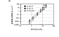
- FIG. 2 is a characteristic diagram showing the gas pressure dependence of the dissociation rate of oxygen gas in the oxygen radical supply device 7 of the present embodiment.
- the dissociation rate of oxygen gas is defined by the molar ratio of the oxygen radical concentration to the oxygen gas concentration (hereinafter, also referred to as O / O 2).
- the discharge power density is obtained by dividing the discharge power (unit: W) by the volume of the discharge portion inside the discharge tube 72 (unit: cm 3).
- the horizontal axis represents the gas pressure inside the discharge pipe 72
- the vertical axis represents the discharge power density.
- SED Specific Energy Density
- the gas pressure is P (unit: Pa)
- the discharge power density is W.
- FIG. 3 is a characteristic diagram showing the gas temperature dependence of the dissociation rate of oxygen gas in the oxygen radical supply device 7 of the present embodiment.
- the horizontal axis represents the gas temperature inside the discharge pipe 72
- the vertical axis represents the discharge power density.
- the conditions for measuring the characteristics shown in FIG. 3 are that the gas pressure inside the discharge tube 72 is 10 kPa and the SED is 1 J / cm 3 .
- FIGS. 2 and 3 are the results when the discharge tube is depressurized by using the gas-gas ejector in the oxygen radical generator 1 of the present embodiment. Similar results can be obtained when the gas pressure inside the discharge pipe 72 is reduced from 1 kPa to 20 kPa by using pumps such as a vacuum pump and a mechanical booster pump, and a blower such as a turbo fan instead of the gas-gas ejector.
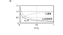
- FIG. 4 is a characteristic diagram showing ozone generation characteristics in the oxygen radical supply device 7 of the present embodiment.
- the characteristic shown in FIG. 4 is the ozone generation characteristic when the oxygen radical generated by the oxygen radical supply device 7 is released into the atmosphere. This condition corresponds to the case where the first gas does not exist.
- the conditions for measuring the characteristics shown in FIG. 4 are that the gas pressure inside the discharge tube 72 is 6.67 kPa, the gas temperature is 600 K, and the discharge power density is 1 kW / cm 3 . 4, the horizontal axis represents the dissociation rate of the oxygen gas (O / O 2), the vertical axis represents the conversion efficiency, the production efficiency of the O 3 concentration and O 3 generated from O to O 3.
- the conversion efficiency from O to O 3 is defined by the molar ratio at which ozone gas is converted to oxygen gas (hereinafter also referred to as O 3 / O)).
- the generation efficiency of the O 3 is defined by the product of the conversion efficiency from the product efficiency and O radicals O radicals to O 3.
- the conversion efficiency from O to O 3 is a numerical value on the vertical axis.
- O 3 concentration is a value obtained by multiplying the 10% value of the vertical axis.
- the generation efficiency of O 3 is a value obtained by multiplying the numerical value on the vertical axis by 10 18 particles / J.
- the solid line shows the conversion efficiency from O to O 3 (O 3 / O)
- the broken line shows the production efficiency of O 3
- the alternate long and short dash line shows the O 3 concentration.
- the unit gO 3 is a value obtained by converting the amount of ozone produced into mass.
- FIG. 5 is a characteristic diagram in which the cost with respect to the ozone concentration is estimated in the oxygen radical generator of the present embodiment.
- the horizontal axis represents the ozone concentration
- the vertical axis represents the cost (yen) required to generate 1 kg of ozone.
- black circles indicate electricity costs
- black squares indicate gas costs
- the horizontal axis represents the dilution ratio of the oxygen gas
- the vertical axis represents the conversion efficiency (O 3 / O), the generation efficiency of the O 3 concentration and O 3 generated from O to O 3.
- the dilution ratio D of the oxygen gas, the flow rate of the second gas supplied from the oxygen radical supply device 7 is Q
- the conversion efficiency from O to O 3 is a numerical value on the vertical axis.
- O 3 concentration is a value obtained by multiplying the 100 g / Nm 3 in the figures the vertical axis.
- the O 3 generation efficiency is a value obtained by multiplying the value on the vertical axis by 500 gO 3 / kWh.
- black circles conversion efficiency from O to O 3 (O 3 / O), the black squares O 3 concentration, the black triangles show the generation efficiency of the O 3.
- FIG. 7 is a diagram showing the characteristics of the oxygen radical generator of the present embodiment as a table when the dilution ratios are 1, 10 and 100.
- the ozone concentration is about 1/25 as compared with the case where the second gas is diluted 1-fold.
- the ozone concentration becomes 1/25 instead of 1/100, so the conversion efficiency from O radicals to O 3 and the production efficiency of O 3 are improved by about 5.5 times, respectively. You can see that it does. It can also be seen that even in the case of 10-fold dilution, the conversion efficiency from O radicals to O 3 and the production efficiency of O 3 are each improved by about 2.4 times.
- the conversion efficiency of O radicals to O 3 and the production efficiency of O 3 can be improved. More preferably, by diluting the second gas containing oxygen radicals with the first gas containing oxygen about 100 times, the conversion efficiency from O radicals to O 3 and the production efficiency of O 3 can be further improved. ..
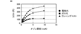
- FIG. 8 is a characteristic diagram in which the cost with respect to the ozone concentration is estimated in the oxygen radical generator 1 of the present embodiment.
- the horizontal axis represents the ozone concentration
- the vertical axis represents the cost (yen) required to generate 1 kg of ozone.
- Costs shown in FIG. 8 an electric bill 15 yen / kWh, an oxygen gas prices was 25 yen / m 3.
- black circles indicate electricity costs
- black squares indicate gas costs
- black triangles indicate running costs.
- the ozone concentration is 9.71%, there is no dilution
- the ozone concentration is 5%
- the dilution ratio is 2
- the ozone concentration is 0.38%
- the dilution ratio is 100.
- the running cost decreases as the dilution ratio increases.
- FIG. 9 is a diagram showing as a table the costs when the dilution ratios are 1, 10 and 100 in the oxygen radical generator 1 of the present embodiment.
- the cost in FIG. 9 is a relative cost when the cost of the oxygen radical generator used in the current water treatment system is 1.
- the second gas is not diluted with the first gas.
- FIG. 9 by setting the dilution ratio to 100, it is possible to realize a running cost of about 1/3 of the running cost of the current oxygen radical generator.
- FIG. 10 is a characteristic diagram showing the ozone generation characteristics when the second gas is diluted with air containing 2.3% of water as the first gas in the oxygen radical generator 1 of the present embodiment. .. 2.3% moisture in air corresponds to a saturated vapor pressure of 1 atmosphere at 20 ° C. 10
- the horizontal axis represents the dilution ratio of the oxygen gas
- the vertical axis represents the conversion efficiency (O 3 / O), the generation efficiency of the O 3 concentration and O 3 generated from O to O 3.
- the conversion efficiency from O to O 3 is a numerical value on the vertical axis.
- O 3 concentration is a value obtained by multiplying the 100 g / Nm 3 in the figures the vertical axis.
- the O 3 generation efficiency is a value obtained by multiplying the value on the vertical axis by 100 gO 3 / kWh.
- black circles conversion efficiency, a black square from O to O 3 O 3 concentration, the black triangles show the generation efficiency of the O 3. As shown in FIG. 10, it can be seen that the O 3 concentration is lowered in accordance with increasing dilution ratio.
- FIG. 11 is a characteristic diagram showing the ozone generation efficiency with respect to the water content of the first gas in the oxygen radical generator 1 of the present embodiment.
- the characteristics shown in FIG. 11 are the characteristics when the dilution ratio is 100 times.
- the horizontal axis is the water content of air, which is the first gas
- the vertical axis is the relative value of ozone production efficiency.
- the ozone generation efficiency decreases as the water content increases.
- an ozone generation efficiency of 50% or more can be obtained with respect to the ozone production efficiency when the water content is zero.
- a humidity controller 22 is provided on the outlet side of the high pressure pump 2.
- the water content of air as the first gas is set to 0.5% or less, that is, the dew point is 0 ° C. or less.
- the oxygen radical generator of the present embodiment includes an oxygen radical supply device that supplies oxygen radicals from a direction intersecting the flow direction of the oxygen-containing gas in the gas mixing region, and supplies the oxygen radicals. Since the device is provided with a discharge unit through which oxygen gas having a gas pressure of 1 kPa to 50 kPa flows, and a discharge power application unit that supplies discharge power to the discharge unit to generate plasma discharge and generate oxygen radicals, oxygen radicals are provided. Generation efficiency can be increased. As a result, the ozone generation efficiency can be increased.
- FIG. 12 is a block diagram of the oxygen radical generator according to the second embodiment.
- the oxygen radical generator 1 of the present embodiment as shown in FIG. 12, two gas-gas ejectors 6 similar to those of the first embodiment are connected in series.
- An oxygen radical supply device 7 is connected to each of the two gas-gas ejectors 6.
- an oxygen gas supply device 8 is connected to each of the two oxygen radical supply devices 7.
- the operations of the two gas-gas ejectors 6 and the two oxygen radical supply devices 7 are the same as those of the first embodiment.
- the ozone concentration can be increased by connecting two gas-gas ejectors 6 in series.
- the number of gas-gas ejectors 6 connected in series may be three or more.
- oxygen gas supply device 8 is connected to each of the two oxygen radical supply devices 7, oxygen gas may be supplied from one oxygen gas supply device 8 to the two oxygen radical supply devices 7. Further, electric power may be supplied from one power source common to each coil of the two oxygen radical supply devices 7.
- FIG. 13 is a block diagram of the oxygen radical generator according to the third embodiment.
- the oxygen radical generator of the present embodiment is the oxygen radical generator described in the first embodiment, in which the rising characteristic of the discharge is improved.
- the upstream gas pipe 71 of the oxygen radical supply device 7 is provided with a gas introduction pipe 71a for introducing gas from an oblique lateral direction.
- the lower figure of FIG. 13 shows a cross-sectional view of the upstream gas pipe 71 provided with the gas introduction pipe 71a.
- An oxygen gas supply device 8 is connected to the gas introduction pipe 71a.
- a metal ring 96 is arranged on the outer periphery of the discharge pipe 72 at a position on the upstream side of the gas of the discharge pipe 72.
- the metal ring 96 is set to a ground potential via a capacitor 97.
- the inert gas supply device 10 is provided in parallel with the oxygen gas supply device 8.
- the inert gas supply device 10 includes, for example, an inert gas tank 101 for storing the inert gas argon gas, a humidity regulator 102, a valve 103, a flow rate regulator 104, and a check valve 105.
- the inert gas supply device 10 supplies the inert gas to the gas introduction pipe 71a.
- the inert gas may be helium gas in addition to argon gas.
- the oxygen gas introduced from the gas introduction pipe 71a flows inside the discharge pipe 72 while spirally circulating, so that the inductively coupled plasma is easily ignited.
- a spiral flow can be generated more effectively. Can be done.
- the inner diameter of the gas introduction pipe 71a is set to 1/2 or less of the inner diameter of the upstream gas pipe 71, the flow velocity of oxygen gas passing through the gas introduction pipe 71a can be increased. Therefore, the gas pressure of the discharge pipe 72 can be lowered.
- the start of plasma discharge becomes easy. Further, when the oxygen radical supply device 7 is started, a discharge is generated between the coil 74 to which a high voltage is applied and the metal ring 96. Since this discharge serves as a pilot light for starting the main discharge, the oxygen radical supply device 7 can be easily started. However, if too much energy enters the pilot discharge, the energy supplied to the main discharge will be insufficient. By adjusting the capacity of the capacitor 97, the amount of energy of the pilot fire discharge can be adjusted.
- a Tesla coil may be provided at a position on the upstream side of the gas of the discharge tube 72. The method of generating a pilot fire with this Tesla coil also facilitates the start of discharge.
- the oxygen radical generator 1 of the present embodiment includes the inert gas supply device 10, and can start the discharge by flowing the inert gas at the time of startup. Once the discharge starts, it is easy to maintain the discharge.
- the flow rate of the inert gas is gradually reduced and the flow rate of the oxygen gas is increased, and finally the discharge is controlled only by the oxygen gas. be able to. By starting the discharge in such a way, the rising characteristic of the discharge can be improved.
- the rising characteristic of the discharge can be improved by controlling the flow rate of the oxygen gas without using the inert gas.
- the flow rate of the oxygen gas supplied from the oxygen gas supply device 8 to the oxygen radical supply device 7 is reduced, and the supply of power to the coil 74 is started in that state. Then, since the gas pressure inside the discharge tube 72 is low, it becomes easy to start the discharge. After the discharge is started, the flow rate of oxygen gas can be gradually increased to raise the gas pressure inside the discharge tube 72 to stably maintain the discharge.
Landscapes
- Chemical & Material Sciences (AREA)
- Organic Chemistry (AREA)
- Inorganic Chemistry (AREA)
- Health & Medical Sciences (AREA)
- General Health & Medical Sciences (AREA)
- Toxicology (AREA)
- Chemical Kinetics & Catalysis (AREA)
- Oxygen, Ozone, And Oxides In General (AREA)
Abstract
効率よく酸素ラジカルを空気に注入することができる酸素ラジカル発生装置を提供する。 酸素を含む第一ガスが供給される第一ガス供給部(62)と、酸素を含む第二ガスが供給される第二ガス供給部(71)と、第二ガス供給部に供給された第二ガスに放電処理を施して酸素ラジカルを発生させる放電処理部(72)と、放電処理部によって放電処理が施された前記第二ガスと前記第一ガス供給部に供給された第一ガスとを混合した混合ガスを生成する混合部(63)と、混合部によって生成された混合ガスを排出する混合ガス排出部(65)とを備えている。
Description
本願は、酸素ラジカル発生装置および酸素ラジカル発生方法に関する。
一般的なオゾン発生装置は、放電を用いてオゾンを発生している。このオゾン発生装置においては、放電空間における電子衝突で酸素ガス(O2)が解離されて酸素ラジカル(O)が生成され(O2+e→O+O+e、eは電子を示す)、生成された酸素ラジカルと周辺に存在する酸素ガスとが結合されてオゾン(O3)が生成される(O+O2+M→O3+M、Mは第三体を示す)。このオゾン発生装置においては、以下の2つの根本的な課題が知られている。
1つは、オゾンの発生効率が低くなることである。放電空間ではオゾンの生成反応と同時にオゾンの分解反応(O3+e→O+O2+e)も起こるため、オゾンの発生効率が低くなる。もう1つは、比較的高価な誘電体バリア放電システムが必要なことである。オゾンの生成反応が発熱反応であるため、反応エネルギーを吸収するための第三体(M)が必要である。そのため、ガス圧が1気圧(101kPa)以上での動作が求められ、安定な放電を維持するためには比較的高価な誘電体バリア放電システムが必要となる。
これらの課題を解決する従来のオゾン発生装置として、空気が流れる第一ガス配管と酸素ガスが流れる第二ガス配管とを同軸状に配置し、内管にあたる第一ガス配管を接地電極として用い、外管にあたる第二ガス配管を高電圧電極として用い、誘電体バリア放電で酸素ガス中に酸素プラズマを発生させるオゾン発生装置が開示されている。このオゾン発生装置は、ガス-ガスエジェクタのベンチュリー効果で第二ガス配管内に低ガス圧の放電空間を形成し、その放電空間で酸素プラズマを発生させて酸素ラジカルを生成している。そして、このオゾン発生装置は、生成した酸素ラジカルを空気に直接注入してオゾンを発生させている。このオゾン発生装置においては、放電空間が低ガス圧状態のため酸素ラジカルと第三体との衝突が起こる確率は低い。その結果、放電空間ではオゾンが生成されず、酸素ラジカルの状態が保持される(例えば、特許文献1参照)。
従来のオゾン発生装置においては、空気が流れる第一ガス配管を電極として使用するため、放電空間は常温の空気によって冷却される。しかしながら、酸素ラジカルは低温では寿命が短い。また、放電空間と酸素ラジカルが空気に注入される位置とが離れているため、放電空間で生成された酸素ラジカルが有効に空気に注入されないという問題があった。
本願は上述のような課題を解決するためになされたもので、効率よく酸素ラジカルを空気に注入することができる酸素ラジカル発生装置を提供することを目的とする。
本願の酸素ラジカル発生装置は、酸素を含む第一ガスが供給される第一ガス供給部と、酸素を含む第二ガスが供給される第二ガス供給部と、第二ガス供給部に供給された第二ガスに放電処理を施して酸素ラジカルを発生させる放電処理部と、放電処理部によって放電処理が施された第二ガスと第一ガス供給部に供給された第一ガスとを混合した混合ガスを生成する混合部と、混合部によって生成された混合ガスを排出する混合ガス排出部とを備えている。
本願の酸素ラジカル発生装置は、酸素を含む第一ガスが供給される第一ガス供給部と、酸素を含む第二ガスが供給される第二ガス供給部と、第二ガス供給部に供給された第二ガスに放電処理を施して酸素ラジカルを発生させる放電処理部と、放電処理部によって放電処理が施された第二ガスと第一ガス供給部に供給された第一ガスとを混合した混合ガスを生成する混合部と、混合部によって生成された混合ガスを排出する混合ガス排出部とを備えているので、効率よく酸素ラジカルを第一ガスに注入することができる。
以下、本願を実施するための実施の形態に係る酸素ラジカル発生装置について、図面を参照して詳細に説明する。なお、各図において同一符号は同一もしくは相当部分を示している。
実施の形態1.
図1は、実施の形態1に係る酸素ラジカル発生装置の構成図である。本実施の形態の酸素ラジカル発生装置1は、ガス-ガスエジェクタ6と酸素ラジカル供給装置7とで構成されている。ガス-ガスエジェクタ6は円筒形状であり、供給口61、ノズル62、ガス混合領域63、ディフューザ64および排出口65で構成されている。供給口61には、外部から第一ガス21が供給される。第一ガスは酸素含有ガスであり、本実施の形態においては空気を用いている。第一ガスである空気は、高圧ポンプ2で供給口61に供給される。図1において、白矢印は第一ガス21の流れる方向を示している。ノズル62は、下流側に向かって縮小角度が約45度で管路断面積を徐々に絞った構成である。ディフューザ64は、下流側に向かって拡大角度が約10度で管路断面積を徐々に拡げた構成である。ガス-ガスエジェクタ6において、高圧ポンプ2で加圧された第一ガス21は、供給口61から供給され、ノズル62で流速が増加される。流速が最大になった第一ガス21は、ガス混合領域63を通過し、ディフューザ64で圧力回復が行われ、排出口65から排出される。
図1は、実施の形態1に係る酸素ラジカル発生装置の構成図である。本実施の形態の酸素ラジカル発生装置1は、ガス-ガスエジェクタ6と酸素ラジカル供給装置7とで構成されている。ガス-ガスエジェクタ6は円筒形状であり、供給口61、ノズル62、ガス混合領域63、ディフューザ64および排出口65で構成されている。供給口61には、外部から第一ガス21が供給される。第一ガスは酸素含有ガスであり、本実施の形態においては空気を用いている。第一ガスである空気は、高圧ポンプ2で供給口61に供給される。図1において、白矢印は第一ガス21の流れる方向を示している。ノズル62は、下流側に向かって縮小角度が約45度で管路断面積を徐々に絞った構成である。ディフューザ64は、下流側に向かって拡大角度が約10度で管路断面積を徐々に拡げた構成である。ガス-ガスエジェクタ6において、高圧ポンプ2で加圧された第一ガス21は、供給口61から供給され、ノズル62で流速が増加される。流速が最大になった第一ガス21は、ガス混合領域63を通過し、ディフューザ64で圧力回復が行われ、排出口65から排出される。
ガス混合領域63は、ノズル62から噴射された高速の第一ガス21のベンチュリー効果によって数kPaから50kPaの負圧状態になる。このガス混合領域63は、第一ガス21の流れと交差する方向、例えば直交する方向からガスを供給するためのガス供給口66を備えている。負圧状態となったガス混合領域63では、ガス供給口66から第二ガスが吸い込まれ、第一ガス21と第二ガスとが混合される。ガス供給口66には、酸素ラジカル供給装置7が接続されている。
酸素ラジカル供給装置7は、上流ガス配管71と放電管72と下流ガス配管73とを備えている。放電管72の外周には誘導結合用のコイル74が設けられている。また、放電管72の外側には断熱外管75が設けられており、放電管72と断熱外管75との間には断熱材76が充填されている。コイル74には、交流電源77が接続されている。酸素ラジカル供給装置7は、上流ガス配管71に供給される酸素を放電管72および下流ガス配管73を経由して、ガス-ガスエジェクタ6のガス供給口66に酸素ラジカルを含む第二ガスを供給する。
酸素ラジカル供給装置7の上流ガス配管71には、酸素ガス供給装置8が接続されている。酸素ガス供給装置8は、酸素ガスタンク81、湿度調整器82、バルブ83、流量調整器84および逆止弁85を備えている。酸素ガスタンク81には露点40℃以下の高純度の乾燥された酸素ガスが貯蔵されている。酸素ガス供給装置8は、酸素ラジカル供給装置7へ高純度の酸素ガスを供給する。
酸素ラジカル供給装置7は、交流電源77からコイル74に交流電圧を印加することで、放電管72の内部に高電圧および高周波数の変動磁場を発生させ、放電管72内部にプラズマ放電空間を発生させる。つまり、コイル74と交流電源77とで放電電力印加部を構成している。このプラズマ放電空間に酸素ガスが供給されると、このプラズマ放電空間では、電子衝突で酸素ラジカル(O)が生成される(O2+e→O+O+e、eは電子を示す)。酸素ラジカル発生装置1は、酸素ラジカル供給装置7で生成された酸素ラジカルを含む第二ガスをガス-ガスエジェクタ6のガス混合領域63を流れる第一ガス21に注入する。このようにして酸素ラジカル発生装置1は、第一ガスである空気に酸素ラジカルを注入することでオゾンを発生させる(O+O2→O3)。
放電管72の内部で生成された酸素ラジカルは500K以下の低温では寿命が短い。本実施の形態の酸素ラジカル発生装置1においては、放電管72の外側に断熱外管75を設け、さらに放電管72と断熱外管75との間に断熱材76を充填している。そのため、放電管72内部のプラズマ放電空間の温度は、500Kから2000Kに保持される。そのため、放電管72内部で生成された酸素ラジカルは長時間その状態を保つことができ、放電管72の内部に高密度の酸素ラジカルを生成させることができる。その結果、酸素ラジカル発生装置1のオゾン発生能力を飛躍的に向上させることができる。
プラズマ放電空間で生成した酸素ラジカルは、プラズマ放電空間を離れると数マイクロ秒のオーダーで急速に失活する(O+O→O2)。そのため、酸素ラジカルが失活する前に酸素ラジカルを含む第二ガスを第一ガスに注入する必要がある。したがって、酸素ラジカルがプラズマ放電空間を離れてからガス混合領域63に到達するまでの移動時間を1msec以下にする必要がある。本実施の形態の酸素ラジカル発生装置1においては、酸素ラジカル供給装置7をガス混合領域63に隣接して配置し、下流ガス配管73の長さを10cm以下としている。
ガス-ガスエジェクタ6は、酸素ラジカル(O)オゾン(O3)、過酸化水素(H2O2)、OHラジカルなどの活性ガスに曝される。そのため、ガス-ガスエジェクタ6の材料は耐食性の高い材料であることが望ましい。ガス-ガスエジェクタ6の材料としては、例えばPTFE(ポリテトラフルオロエチレン)、PFA(ペルフルオロアルコキシアルカン)などのフッ素樹脂、ステンレス(SUS316、SUS304など)などの金属材料、または表面がフッ素樹脂で被覆された材料などを用いることができる。酸素ラジカル供給装置7の放電管72の材料は、高温に耐える誘電体が望ましい。放電管72は、例えば石英、耐熱性を有するホウケイ酸ガラスなどのガラス類、またはアルミナ、ジルコニアなどのセラミクス類を用いることができる。また、図1に示す酸素ラジカル供給装置7において、上流ガス配管71と放電管72と下流ガス配管73とを異なる構成としたが、1本の管状の誘電体で構成してもよい。これらを1本の管状の誘電体で構成することは、非プラズマ放電空間を狭くすることに有効である。
酸素ラジカル発生装置1において、酸素ラジカルをプラズマ放電空間で高効率かつ高濃度に生成し、高効率にガス混合領域63に供給するためには、プラズマ放電空間のガス温度を上げること、およびプラズマ放電空間からガス混合領域63までの酸素ラジカルの移動時間を短くすることが重要である。
プラズマ放電空間のガス温度を上げるために、本実施の形態の酸素ラジカル供給装置7においては、放電管72の外周に断熱外管75が設置されている。この断熱外管75は、コイル74の電磁波の漏洩を抑え、かつプラズマ放電空間の熱を外部に逃さない機能を有する。電磁波の漏洩を抑える目的で、断熱外管75として金属管を使用することができる。または、断熱外管75として絶縁管の内表面および外表面の少なくとも一方に導電性皮膜を施したものを使用することができる。さらに、断熱効果を向上させかつ電気絶縁性を確保する目的で、本実施の形態の酸素ラジカル供給装置7においては、放電管72と断熱外管75との間には断熱材76が充填されている。断熱材76としては、断熱性および電気絶縁性に優れ、かつ熱膨張時に放電管72にストレスを与えないようにシリコン系のゴムを用いている。
プラズマ放電空間からガス混合領域63までの酸素ラジカルの移動時間を短くするために、本実施の形態の酸素ラジカル供給装置7においては、放電管72をガス混合領域63の近傍に設置すると共に、下流ガス配管73の内部に絞り78を設置している。
図1に示す酸素ラジカル供給装置7において、実験の結果、ガス流の影響でプラズマ放電空間内の荷電粒子がガス下流方向に流され、放電管72よりもガス下流側にプラズマ放電が伸長することが判明した。とくに下流ガス配管73の長さを5cm以下にすることで、プラズマ放電はガス混合領域63まで伸長し、酸素ラジカルは非プラズマ放電空間を通過することなく第一ガスに注入することができることが判明した。本実施の形態の酸素ラジカル発生装置1においては、下流ガス配管73を除いて、ガス-ガスエジェクタ6のガス供給口66に放電管72を直接接続してもよい。また、本実施の形態の酸素ラジカル供給装置7においては、図1に示すように、下流ガス配管73の内部に絞り78を設置している。この絞り78は、下流ガス配管73の管路断面積をガス流の下流側に向かって徐々に小さくしたものである。絞り78を設置することで、下流ガス配管73内のガスの流速が増大し、酸素ラジカルがプラズマ放電空間を離れてからガス混合領域63に到達するまでの移動時間を短くすることができる。酸素ラジカルの寿命を考慮すると、酸素ラジカルの非プラズマ放電空間の滞在時間、すなわちプラズマ放電空間からガス混合領域63までの移動時間は1ms以下に設定することが望ましい。
図1に示す酸素ラジカル供給装置7において、実験の結果、ガス流の影響でプラズマ放電空間内の荷電粒子がガス下流方向に流され、放電管72よりもガス下流側にプラズマ放電が伸長することが判明した。とくに下流ガス配管73の長さを5cm以下にすることで、プラズマ放電はガス混合領域63まで伸長し、酸素ラジカルは非プラズマ放電空間を通過することなく第一ガスに注入することができることが判明した。本実施の形態の酸素ラジカル発生装置1においては、下流ガス配管73を除いて、ガス-ガスエジェクタ6のガス供給口66に放電管72を直接接続してもよい。また、本実施の形態の酸素ラジカル供給装置7においては、図1に示すように、下流ガス配管73の内部に絞り78を設置している。この絞り78は、下流ガス配管73の管路断面積をガス流の下流側に向かって徐々に小さくしたものである。絞り78を設置することで、下流ガス配管73内のガスの流速が増大し、酸素ラジカルがプラズマ放電空間を離れてからガス混合領域63に到達するまでの移動時間を短くすることができる。酸素ラジカルの寿命を考慮すると、酸素ラジカルの非プラズマ放電空間の滞在時間、すなわちプラズマ放電空間からガス混合領域63までの移動時間は1ms以下に設定することが望ましい。
酸素ラジカル供給装置7において、始動のときにプラズマの点火が困難な場合がある。本実施の形態の酸素ラジカル供給装置7においては、図1に示すように、放電管72のガスの流入側に金属リング79を設置してもよい。コイル74に交流電圧の印加を開始してプラズマを点火するときにこの金属リング79に電界が集中するので、放電が開始し易くなる。
なお、本実施の形態の酸素ラジカル供給装置7においては、放電管72の外周に巻かれたコイル74を用いて誘導結合プラズマを発生させている。コイルを用いて誘導結合プラズマを発生させる方法以外に、放電管の外部から電磁力を印加することによって放電管の内部にプラズマ放電を発生させる他の方法、例えばDCグロー放電プラズマ、容量結合プラズマ、マイクロ波放電プラズマなどの方法を用いてもよい。
なお、本実施の形態の酸素ラジカル供給装置7においては、放電管72の外周に巻かれたコイル74を用いて誘導結合プラズマを発生させている。コイルを用いて誘導結合プラズマを発生させる方法以外に、放電管の外部から電磁力を印加することによって放電管の内部にプラズマ放電を発生させる他の方法、例えばDCグロー放電プラズマ、容量結合プラズマ、マイクロ波放電プラズマなどの方法を用いてもよい。
次に、本実施の形態の酸素ラジカル供給装置7の性能について説明する。図2は、本実施の形態の酸素ラジカル供給装置7における酸素ガスの解離率に対するガス圧依存性を示す特性図である。ここで、酸素ガスの解離率は、酸素ガス濃度に対する酸素ラジカル濃度のモル比率(これ以降O/O2とも記す)で定義した。また、放電電力密度は、放電電力(単位:W)を放電管72の内部の放電部体積(単位:cm3)で割ったものである。図2において、横軸は放電管72の内部のガス圧、縦軸は放電電力密度である。図2に示す特性の測定の条件は、放電管72の内部のガス温度が600K、比エネルギー密度(SED:Specific Energy Density)が1J/cm3である。ここで、SEDは、放電電力密度(単位:W/cm3)とプラズマ放電空間の酸素ラジカルを含むガスの滞在時間(単位:秒)との積である。
図2において、黒丸はO/O2=2を維持するために必要なガス圧と放電電力密度との関係を示し、黒四角はO/O2=1を維持するために必要なガス圧と放電電力密度との関係を示し、黒三角はO/O2=0.5を維持するために必要なガス圧と放電電力密度との関係を示している。図2から、放電電力密度が同じであれはガス圧が増大するにしたがって酸素ガスの解離率(O/O2)は低下するが、放電電力密度を増大させることで高いガス圧においても解離率(O/O2)が上昇することがわかる。この特性は、発明者が初めて明らかにしものである。
ここで、ガス圧をP(単位:Pa)、放電電力密度をWとする。図2において、回帰分析の結果、O/O2=2、O/O2=1およびO/O2=0.5の回帰曲線はそれぞれW=6.8×P3.1405、W=3.0×P3.0268およびW=1.1×P3.073となることがわかった。したがって、ガス圧Pの条件において、放電電力密度Wを、W>1.1×P3.073に設定することでO/O2>0.5が得られる。さらに、放電電力密度Wを、W>3.0×P3.0268に設定することでさらに高い酸素ガスの解離率(O/O2>1)が得られる。
図3は、本実施の形態の酸素ラジカル供給装置7における酸素ガスの解離率に対するガス温度依存性を示す特性図である。図3において、横軸は放電管72の内部のガス温度、縦軸は放電電力密度である。図3に示す特性の測定の条件は、放電管72の内部のガス圧が10kPa、SEDが1J/cm3である。図3において、黒丸はO/O2=1を維持するために必要なガス温度と放電電力密度との関係を示している。
図3から、ガス温度が高くなるにしたがって酸素の解離率が増大するために同じ酸素の解離率を維持するための放電電力密度は低くなることがわかった。ここで、ガス温度をT(単位:K)、放電電力密度をWとする。図3において、回帰分析の結果、ガス圧が10kPaにおけるO/O2=1の回帰曲線は、W=2×1014×T-3.867となることがわかった。以上の結果から、プラズマ放電空間のガス温度を高くすることで酸素の解離率を高くできる。
酸素プラズマ放電の研究は、半導体製造プロセスに対応した数100mPaから数100Paの低ガス圧領域での研究、またはオゾン生成および表面処理に対応した100kPa以上の高ガス圧領域での研究がほとんどである。1kPaから50kPaの中ガス圧領域での放電電力密度の影響は、今回の検討で初めて明らかになった。図2および図3で示した事実、すなわち同じ放電電力密度の条件では、ガス圧が増大するにしたがって酸素の解離率が低下すること、放電電力密度が増大するにしたがって酸素の解離率が上昇すること、およびガス温度が高くなるにしたがって酸素の解離率が上昇することはこれまで報告された例はなく発明者が初めて見出したものである。
さらに、ガス温度が600Kにおいて、O/O2=1を実現するために必要な放電電力密度W(W/cm3)は、ガス圧P(Pa)に対してW=3.0×P3.0268の関係が成り立つことを見出した。また、ガス圧が10kPaにおいて、O/O2=1を実現するために必要な放電電力密度W(W/cm3)は、ガス温度T(K)に対してW=2×1014×T-3.867の関係が成り立つことを見出した。これらの放電電力密度の臨界値は、高濃度でOラジカルを発生させる酸素ラジカル供給装置の設計基準として極めて重要な値であり、新しい指針となる極めて大きな発見と言える。
なお、図2および図3の結果は、本実施の形態の酸素ラジカル発生装置1において、ガス-ガスエジェクタを用いて放電管を減圧した場合の結果である。ガス-ガスエジェクタの替わりに真空ポンプ、メカニカルブースターポンプなどのポンプ類、ターボファンなどの送風機を用いて放電管72の内部のガス圧を1kPaから20kPaに減圧する場合でも同様の結果が得られる。
図4は、本実施の形態の酸素ラジカル供給装置7におけるオゾンの生成特性を示す特性図である。図4に示す特性は、酸素ラジカル供給装置7で生成された酸素ラジカルを大気中に開放したときのオゾンの生成特性である。この条件は、第一ガスが存在しない場合に相当する。図4に示す特性の測定の条件は、放電管72の内部のガス圧が6.67kPa、ガス温度が600K、放電電力密度が1kW/cm3である。図4において、横軸は酸素ガスの解離率(O/O2)、縦軸はOからO3への変換効率、生成されたO3濃度およびO3の生成効率を示す。ここで、OからO3への変換効率は、オゾンガスが酸素ガスに変換されるモル比率(これ以降O3/O)とも記す)で定義した。また、O3の生成効率は、Oラジカルの生成効率とOラジカルからO3への変換効率との積で定義される。図4において、OからO3への変換効率は、縦軸の数値である。O3濃度は、縦軸の数値に10%をかけた値である。O3の生成効率は、縦軸の数値に1018particles/Jをかけた値である。図4において、実線はOからO3への変換効率(O3/O)を示し、破線はO3の生成効率を示し、一点破線はO3濃度を示している。
図4から、酸素の解離率(O/O2)が増大するにしたがってO3を生成するために必要なO2分子数が減るため、OからO3への変換効率(O3/O)およびO3の生成効率は急速に低下することがわかる。ここで、O/O2=1のときの特性値を下記に示す。
酸素の解離率:O/O2=1
酸素ラジカルの生成効率:1.17×10¹⁸particles/J
オゾンへの変換効率:O3/O=0.139
オゾンの生成効率:1.62×10¹⁷particles/J
(=1.17×10¹⁸particles/J×0.139)
=46.8gO3/kWh
オゾン濃度:9.71mol%=208g/Nm3
ここで、単位gO3は、オゾンの生成量を質量に換算したものである。
酸素の解離率:O/O2=1
酸素ラジカルの生成効率:1.17×10¹⁸particles/J
オゾンへの変換効率:O3/O=0.139
オゾンの生成効率:1.62×10¹⁷particles/J
(=1.17×10¹⁸particles/J×0.139)
=46.8gO3/kWh
オゾン濃度:9.71mol%=208g/Nm3
ここで、単位gO3は、オゾンの生成量を質量に換算したものである。
図5は、本実施の形態の酸素ラジカル発生装置において、オゾン濃度に対するコストを見積もった特性図である。図5において、横軸はオゾン濃度、縦軸はオゾン1kgを生成するときに必要なコスト(円)を示す。図5に示すコストは、電気代を15円/kWh、酸素ガス代を25円/m3とし、図4に示すオゾンの生成特性に基づいて試算した。なお、第一ガスの供給は行われていないので、コストの見積もりに高圧ポンプ2を作動させるための電気代は含まれていない。また、図5において、黒丸は電気代、黒四角はガス代、黒三角はランニングコストを示している。図5から、ランニングコストが最小になるのは、オゾン濃度が約7%(=150g/Nm3)の場合であることがわかる。
次に、O/O2=1の場合に第一ガスの混合量の効果について説明する。図6は、O/O2=1の場合において、第一ガスの混合量に対するオゾンの生成特性を示す特性図である。図6において、横軸は酸素ガスの希釈倍率であり、縦軸はOからO3への変換効率(O3/O)、生成されたO3濃度およびO3の生成効率を示す。ここで、酸素ガスの希釈倍率Dは、酸素ラジカル供給装置7から供給される第二ガスの流量をQとし、高圧ポンプ2から供給される第一ガスである空気の流量をQ1とすると、D=(Q+Q1)/Qで定義される。図6において、OからO3への変換効率は、縦軸の数値である。O3濃度は、縦軸の数値に100g/Nm3をかけた値である。O3の生成効率は、縦軸の数値に500gO3/kWhをかけた値である。図6において、黒丸はOからO3への変換効率(O3/O)、黒四角はO3濃度、黒三角はO3の生成効率を示している。
図6からわかるように、第一ガスの混合量が増加するすなわち希釈倍率が増大すると、オゾン濃度は低下するが、OからO3への変換効率(O3/O)およびO3の生成効率は大幅に増大することがわかる。この特性はO3を生成するために必要なO2が増加したことによる得られる効果である。
図7は、本実施の形態の酸素ラジカル発生装置において、希釈倍率1、10および100の場合の特性を表として示す図である。図7からわかるように、第二ガスが第一ガスで100倍に希釈された場合、1倍に希釈された場合に対してオゾン濃度は約1/25になる。希釈倍率が100倍のときにオゾン濃度が1/100にならずに1/25になるということから、OラジカルからO3への変換効率およびO3の生成効率がそれぞれ約5.5倍向上することがわかる。また、10倍希釈の場合でも、OラジカルからO3への変換効率およびO3の生成効率がそれぞれ約2.4倍向上することがわかる。したがって、酸素ラジカルを含む第二ガスを酸素を含む第一ガスで希釈する場合、10倍以上に希釈するすなわち第二ガスの流量に対して第一ガスの流量を9倍以上に設定することでOラジカルからO3への変換効率およびO3の生成効率を向上させることができる。さらに望ましくは、酸素ラジカルを含む第二ガスを酸素を含む第一ガスで100倍程度に希釈することで、OラジカルからO3への変換効率およびO3の生成効率をさらに向上させることができる。
図8は、本実施の形態の酸素ラジカル発生装置1において、オゾン濃度に対するコストを見積もった特性図である。図8において、横軸はオゾン濃度、縦軸はオゾン1kgを生成するときに必要なコスト(円)を示す。図8に示すコストは、電気代を15円/kWh、酸素ガス代を25円/m3とした。また、図8において、黒丸は電気代、黒四角はガス代、黒三角はランニングコストを示している。ここで、オゾン濃度が9.71%のときが希釈なし、オゾン濃度が5%のときが希釈倍率が2、オゾン濃度が0.38%のときが希釈倍率が100に相当する。図8からわかるように、希釈倍率の増大でランニングコストが低下することがわかる。
図9は、本実施の形態の酸素ラジカル発生装置1において、希釈倍率1、10および100の場合のコストを表として示す図である。図9におけるコストは、現行の水処理システムで使用されている酸素ラジカル発生装置のコストを1とした場合の相対コストである。現行の水処理システムで使用されている酸素ラジカル発生装置においては、第一ガスで第二ガスを希釈することは行われていない。図9からわかるように、希釈倍率を100とすることで、現行の酸素ラジカル発生装置のランニングコストに対して約1/3のランニングコストを実現することができる。
次に、本実施の形態の酸素ラジカル発生装置のおける第一ガスに含まれる水分の影響について説明する。
図10は、本実施の形態の酸素ラジカル発生装置1において、第一ガスとして2.3%の水分を含む空気を用いて第二ガスを希釈したときのオゾンの生成特性を示す特性図である。空気中の2.3%の水分は、20℃で1気圧の飽和蒸気圧に相当する。図10において、横軸は酸素ガスの希釈倍率であり、縦軸はOからO3への変換効率(O3/O)、生成されたO3濃度およびO3の生成効率を示す。図10において、OからO3への変換効率は、縦軸の数値である。O3濃度は、縦軸の数値に100g/Nm3をかけた値である。O3の生成効率は、縦軸の数値に100gO3/kWhをかけた値である。図10において、黒丸はOからO3への変換効率、黒四角はO3濃度、黒三角はO3の生成効率を示している。図10に示すように、希釈倍率が増えるにしたがってO3濃度が低下していくことがわかる。
図10は、本実施の形態の酸素ラジカル発生装置1において、第一ガスとして2.3%の水分を含む空気を用いて第二ガスを希釈したときのオゾンの生成特性を示す特性図である。空気中の2.3%の水分は、20℃で1気圧の飽和蒸気圧に相当する。図10において、横軸は酸素ガスの希釈倍率であり、縦軸はOからO3への変換効率(O3/O)、生成されたO3濃度およびO3の生成効率を示す。図10において、OからO3への変換効率は、縦軸の数値である。O3濃度は、縦軸の数値に100g/Nm3をかけた値である。O3の生成効率は、縦軸の数値に100gO3/kWhをかけた値である。図10において、黒丸はOからO3への変換効率、黒四角はO3濃度、黒三角はO3の生成効率を示している。図10に示すように、希釈倍率が増えるにしたがってO3濃度が低下していくことがわかる。
図11は、本実施の形態の酸素ラジカル発生装置1において、第一ガスの水分含有量に対するオゾンの生成効率を示す特性図である。図11に示す特性は、希釈倍率が100倍のときの特性である。図11において、横軸は第一ガスである空気の水分含有量であり、縦軸はオゾンの生成効率の相対値である。図11に示すように、水分含有量が増えるにしたがってオゾンの生成効率が低下していくことがわかる。水分含有量が0.5%以下であれば、水分含有量がゼロのときのオゾンの生成効率に対して50%以上のオゾン生成効率が得られる。さらに、水分含有量が0.1%以下であれば、水分含有量がゼロのときのオゾンの生成効率に対して80%以上のオゾン生成効率が得られる。水分の影響を調べたところ、希釈用の空気に水分が含まれている場合、Oラジカルがその水分と反応してOH、H2O2などを生成するため、OラジカルからO3への変換が妨げられることが明らかになった。
そこで、本実施の形態の酸素ラジカル発生装置1においては、図1に示すように、高圧ポンプ2の出口側に湿度調整器22を備えている。この湿度調整器22を用いて第一ガスとしての空気の水分含有量を0.5%以下すなわち露点0℃以下としている。従来、酸素ラジカルを含む第二ガスの水分含有量の影響の研究報告はあるが、酸素ラジカルに混合する第一ガスの水分含有量の影響については今回初めて明らかになった。
以上説明したように、本実施の形態の酸素ラジカル発生装置は、ガス混合領域において酸素含有ガスの流れる方向と交差する方向から酸素ラジカルを供給する酸素ラジカル供給装置を備えており、この酸素ラジカル供給装置がガス圧が1kPaから50kPaの酸素ガスが流れる放電部と、放電部に放電電力を供給してプラズマ放電を発生させて酸素ラジカルを生成させる放電電力印加部とを備えているので、酸素ラジカルの生成効率を高くできる。その結果、オゾンの生成効率を高くすることができる。
実施の形態2.
図12は、実施の形態2に係る酸素ラジカル発生装置の構成図である。本実施の形態の酸素ラジカル発生装置1は、図12に示すように、実施の形態1と同様のガス-ガスエジェクタ6が2つ直列に接続されている。2つのガス-ガスエジェクタ6には、酸素ラジカル供給装置7がそれぞれ接続されている。さらに、2つの酸素ラジカル供給装置7には、酸素ガス供給装置8がそれぞれ接続されている。
図12は、実施の形態2に係る酸素ラジカル発生装置の構成図である。本実施の形態の酸素ラジカル発生装置1は、図12に示すように、実施の形態1と同様のガス-ガスエジェクタ6が2つ直列に接続されている。2つのガス-ガスエジェクタ6には、酸素ラジカル供給装置7がそれぞれ接続されている。さらに、2つの酸素ラジカル供給装置7には、酸素ガス供給装置8がそれぞれ接続されている。
本実施の形態の酸素ラジカル発生装置1において、2つのガス-ガスエジェクタ6および2つの酸素ラジカル供給装置7の動作については実施の形態1と同様である。本実施の形態の酸素ラジカル発生装置1は、2つのガス-ガスエジェクタ6を直列に接続することで、オゾン濃度を高くすることができる。なお、ガス-ガスエジェクタ6の直列接続は、3つ以上であってもよい。また、2つの酸素ラジカル供給装置7それぞれに酸素ガス供給装置8を接続しているが、1つの酸素ガス供給装置8から2つの酸素ラジカル供給装置7に酸素ガスを供給してもよい。さらには、2つの酸素ラジカル供給装置7のそれぞれのコイルに共通の1つの電源から電力を供給してもよい。
実施の形態3.
図13は、実施の形態3に係る酸素ラジカル発生装置の構成図である。本実施の形態の酸素ラジカル発生装置は、実施の形態1で説明した酸素ラジカル発生装置において、放電の立ち上がり特性を改善したものである。図13に示すように、本実施の形態においては、酸素ラジカル供給装置7の上流ガス配管71が斜め横方向からガスを導入するためのガス導入配管71aを備えたものである。図13の下の図には、ガス導入配管71aを備えた上流ガス配管71の断面図を示している。このガス導入配管71aには、酸素ガス供給装置8が接続されている。また、放電管72のガスの上流側の位置に、放電管72の外周に金属リング96を配置している。この金属リング96はコンデンサ97を介して接地電位に設定されている。さらに、酸素ガス供給装置8と並列に不活性ガス供給装置10を備えている。不活性ガス供給装置10は、例えば不活性ガスのアルゴンガスを貯蔵した不活性ガスタンク101、湿度調整器102、バルブ103、流量調整器104および逆止弁105を備えている。不活性ガス供給装置10は、ガス導入配管71aに不活性ガスを供給する。なお、不活性ガスとしては、アルゴンガス以外にヘリウムガスでもよい。
図13は、実施の形態3に係る酸素ラジカル発生装置の構成図である。本実施の形態の酸素ラジカル発生装置は、実施の形態1で説明した酸素ラジカル発生装置において、放電の立ち上がり特性を改善したものである。図13に示すように、本実施の形態においては、酸素ラジカル供給装置7の上流ガス配管71が斜め横方向からガスを導入するためのガス導入配管71aを備えたものである。図13の下の図には、ガス導入配管71aを備えた上流ガス配管71の断面図を示している。このガス導入配管71aには、酸素ガス供給装置8が接続されている。また、放電管72のガスの上流側の位置に、放電管72の外周に金属リング96を配置している。この金属リング96はコンデンサ97を介して接地電位に設定されている。さらに、酸素ガス供給装置8と並列に不活性ガス供給装置10を備えている。不活性ガス供給装置10は、例えば不活性ガスのアルゴンガスを貯蔵した不活性ガスタンク101、湿度調整器102、バルブ103、流量調整器104および逆止弁105を備えている。不活性ガス供給装置10は、ガス導入配管71aに不活性ガスを供給する。なお、不活性ガスとしては、アルゴンガス以外にヘリウムガスでもよい。
このように構成された酸素ラジカル発生装置1においては、ガス導入配管71aから導入された酸素ガスが螺旋状に回流しながら放電管72の内部を流れるため、誘導結合プラズマが点火し易くなる。このとき、図13の下の図に示すように、上流ガス配管71の中心軸に対して、ガス導入配管71aの中心軸の方向をずらしておくと、より効果的に螺旋流を発生させることができる。さらに、ガス導入配管71aの内径を上流ガス配管71の内径の1/2以下とすることで、ガス導入配管71aを通過する酸素ガスの流速を速くすることができる。そのため、放電管72のガス圧を低くすることができる。その結果、プラズマ放電の開始が容易となる。また、酸素ラジカル供給装置7の始動時に高電圧が印加されたコイル74と金属リング96との間で放電が発生する。この放電が主放電開始の種火となるため、酸素ラジカル供給装置7の始動が容易となる。ただし、種火放電にエネルギーが入り過ぎると主放電に供給されるエネルギーが不足する。コンデンサ97の容量を調整することで種火放電のエネルギー量を調整することができる。なお、金属リング96とコンデンサ97とに替えて、放電管72のガスの上流側の位置にテスラコイルを設けてもよい。このテスラコイルで種火を発生させる方法でも放電開始が容易になる。
また、酸素ガスは付着性ガスのため放電しにくい。一方、酸素ガスに比べてアルゴンガスおよびヘリウムガスなどの不活性ガスは放電し易い。図13に示したように、本実施の形態の酸素ラジカル発生装置1は、不活性ガス供給装置10を備えており、起動時には不活性ガスを流して放電を開始させることができる。一旦放電が開始すると放電の維持は容易である。本実施の形態においては、不活性ガスを流して放電を開始した後は徐々に不活性ガスの流量を減らすと共に酸素ガスの流量を増やし、最終的には酸素ガスだけで放電するように制御することができる。このような方法で放電を開始することで、放電の立ち上がり特性を改善することができる。
なお、図13に示す酸素ラジカル発生装置1において、不活性ガスを使用せず、酸素ガスの流量を制御することで放電の立ち上がり特性を改善することもできる。酸素ガス供給装置8から酸素ラジカル供給装置7に供給する酸素ガスの流量を絞り、その状態でコイル74への電力の供給を開始する。そうすると放電管72内部のガス圧は低いため、放電開始が容易となる。放電が開始された後は酸素ガスの流量を徐々に増加させて放電管72内部のガス圧を上昇させて安定に放電を保持することができる。
本願は、様々な例示的な実施の形態および実施例が記載されているが、1つ、または複数の実施の形態に記載された様々な特徴、態様、および機能は特定の実施の形態の適用に限られるのではなく、単独で、または様々な組み合わせで実施の形態に適用可能である。
したがって、例示されていない無数の変形例が、本願明細書に開示される技術の範囲内において想定される。例えば、少なくとも1つの構成要素を変形する場合、追加する場合または省略する場合、さらには、少なくとも1つの構成要素を抽出し、他の実施の形態の構成要素と組み合わせる場合が含まれるものとする。
したがって、例示されていない無数の変形例が、本願明細書に開示される技術の範囲内において想定される。例えば、少なくとも1つの構成要素を変形する場合、追加する場合または省略する場合、さらには、少なくとも1つの構成要素を抽出し、他の実施の形態の構成要素と組み合わせる場合が含まれるものとする。
1 酸素ラジカル発生装置、2 高圧ポンプ、6 ガス-ガスエジェクタ、7 酸素ラジカル供給装置、8 酸素ガス供給装置、10 不活性ガス供給装置、21 第一ガス、22、82、102 湿度調整器、61 供給口、62 ノズル、63 ガス混合領域、64 ディフューザ、65 排出口、66 ガス供給口、71 上流ガス配管、72 放電管、73 下流ガス配管、74 コイル、75 断熱外管、76 断熱材、77 交流電源、78 絞り、79、96 金属リング、81 酸素ガスタンク、83、103 バルブ、84、104 流量調整器、85、105 逆止弁、97 コンデンサ、101 不活性ガスタンク。
Claims (15)
- 酸素ラジカルを発生する酸素ラジカル発生装置において、
酸素を含む第一ガスが供給される第一ガス供給部と、
酸素を含む第二ガスが供給される第二ガス供給部と、
前記第二ガス供給部に供給された前記第二ガスに放電処理を施して前記酸素ラジカルを発生させる放電処理部と、
前記放電処理部によって前記放電処理が施された前記第二ガスと前記第一ガス供給部に供給された前記第一ガスとを混合した混合ガスを生成する混合部と、
前記混合部によって生成された前記混合ガスを排出する混合ガス排出部とを備えることを特徴とする酸素ラジカル発生装置。 - 前記放電処理部によって前記放電処理が施された前記第二ガスを前記混合部へと導く出口部位を更に備え、
前記出口部位は、前記第一ガス供給部から前記混合ガス排出部へと向かうガス流方向に交差する交差方向で前記混合部と接続してあることを特徴とする請求項1に記載の酸素ラジカル発生装置。 - ガス流方向に沿って前記第一ガス供給部と前記混合部との間に位置し、前記第一ガス供給部側から前記混合部側へ向かって縮径するよう構成してあり、前記第一ガス供給部に供給された前記第一ガスを前記混合部へと導くノズル部位と、
前記ガス流方向に沿って前記混合部と前記混合ガス排出部との間に位置し、前記混合部側から前記混合ガス排出部側へ向かって拡径するよう構成してあり、前記混合部において混合された前記混合ガスを前記混合ガス排出部へと導くディフューザ部位とを備える
ことを特徴とする請求項1または2に記載の酸素ラジカル発生装置。 - 前記放電処理部における前記第二ガスのガス圧が1kPaから50kPaであることを特徴とする請求項1から3のいずれか1項に記載の酸素ラジカル発生装置。
- 前記放電処理の電力を前記放電処理部の放電体積で割った値である放電電力密度をWとし、前記放電処理部を流れる前記第二ガスのガス圧をPとしたときに、W>1.1×P3.073を満足することを特徴とする請求項1から4のいずれか1項に記載の酸素ラジカル発生装置。
- 前記第一ガスの流量をQ1とし、前記第二ガスの流量をQとしたときに、(Q+Q1)/Q≧10を満足することを特徴とする請求項1から5のいずれか1項に記載の酸素ラジカル発生装置。
- 前記酸素ラジカル発生装置は、前記放電処理部に不活性ガスを供給する不活性ガス供給部をさらに備え、前記放電処理の電力の印加を開始するときに前記不活性ガス供給部から前記不活性ガスを供給し、放電が発生した後に前記不活性ガスの供給を減らし前記第二ガスの流量を増やすことを特徴とする請求項1から6のいずれか1項に記載の酸素ラジカル発生装置。
- 前記第一ガスの水分含有量を0.5%以下としたことを特徴とする請求項1から7のいずれか1項に記載の酸素ラジカル発生装置。
- 酸素ラジカルを発生する酸素ラジカル発生方法において、
酸素を含む第一ガスを第一ガス供給部に供給する第一ガス供給ステップと、
酸素を含む第二ガスを第二ガス供給部に供給する第二ガス供給ステップと、
前記第二ガス供給部に供給された前記第二ガスに放電処理を施して前記酸素ラジカルを発生させる放電処理ステップと、
前記放電処理ステップによって前記放電処理が施された前記第二ガスと前記第一ガス供給部に供給された前記第一ガスとを混合部で混合して混合ガスを生成する混合ステップと、
前記混合ステップによって生成された前記混合ガスを混合ガス排出部から排出する混合ガス排出ステップとを備えることを特徴とする酸素ラジカル発生方法。 - 前記放電処理ステップによって前記放電処理が施された前記第二ガスを、前記第一ガス供給部から前記混合ガス排出部へと向かうガス流方向に交差する交差方向で前記混合部へと導く第二ガス誘導ステップを更に備えることを特徴とする請求項9に記載の酸素ラジカル発生方法。
- ガス流方向に沿って前記第一ガス供給部と前記混合部との間に位置し、前記第一ガス供給部側から前記混合部側へ向かって縮径するよう構成してあり、前記第一ガス供給部に供給された前記第一ガスを前記混合部へと導くノズル部位を準備するノズル部位準備ステップと、
前記ガス流方向に沿って前記混合部と前記混合ガス排出部との間に位置し、前記混合部側から前記混合ガス排出部側へ向かって拡径するよう構成してあり、前記混合部において混合された前記混合ガスを前記混合ガス排出部へと導くディフューザ部位を準備するディフューザ部位準備ステップとを備える
ことを特徴とする請求項9または10に記載の酸素ラジカル発生方法。 - 前記放電処理ステップにおける前記第二ガスのガス圧が1kPaから50kPaであることを特徴とする請求項9から11のいずれか1項に記載の酸素ラジカル発生方法。
- 前記放電処理ステップにおける前記放電処理の電力を放電体積で割った値である放電電力密度をWとし、前記第二ガスのガス圧をPとしたときに、W>1.1×P3.073を満足することを特徴とする請求項9から12のいずれか1項に記載の酸素ラジカル発生方法。
- 前記混合ステップにおける前記第一ガスの流量をQ1とし、前記第二ガスの流量をQとしたときに、(Q+Q1)/Q≧10を満足することを特徴とする請求項9から13のいずれか1項に記載の酸素ラジカル発生方法。
- 前記放電処理ステップの前に、不活性ガスに放電処理を行って放電を開始させる放電開始ステップをさらに備えたことを特徴とする請求項9から14のいずれか1項に記載の酸素ラジカル発生方法。
Priority Applications (3)
| Application Number | Priority Date | Filing Date | Title |
|---|---|---|---|
| CN202080096008.6A CN115427348B (zh) | 2020-04-09 | 2020-04-09 | 氧自由基产生装置及氧自由基产生方法 |
| PCT/JP2020/015951 WO2021205593A1 (ja) | 2020-04-09 | 2020-04-09 | 酸素ラジカル発生装置および酸素ラジカル発生方法 |
| JP2020541826A JP6818953B1 (ja) | 2020-04-09 | 2020-04-09 | 酸素ラジカル発生装置および酸素ラジカル発生方法 |
Applications Claiming Priority (1)
| Application Number | Priority Date | Filing Date | Title |
|---|---|---|---|
| PCT/JP2020/015951 WO2021205593A1 (ja) | 2020-04-09 | 2020-04-09 | 酸素ラジカル発生装置および酸素ラジカル発生方法 |
Publications (1)
| Publication Number | Publication Date |
|---|---|
| WO2021205593A1 true WO2021205593A1 (ja) | 2021-10-14 |
Family
ID=74200187
Family Applications (1)
| Application Number | Title | Priority Date | Filing Date |
|---|---|---|---|
| PCT/JP2020/015951 Ceased WO2021205593A1 (ja) | 2020-04-09 | 2020-04-09 | 酸素ラジカル発生装置および酸素ラジカル発生方法 |
Country Status (3)
| Country | Link |
|---|---|
| JP (1) | JP6818953B1 (ja) |
| CN (1) | CN115427348B (ja) |
| WO (1) | WO2021205593A1 (ja) |
Cited By (1)
| Publication number | Priority date | Publication date | Assignee | Title |
|---|---|---|---|---|
| RU2856179C1 (ru) * | 2024-10-31 | 2026-02-11 | Общество с ограниченной ответственностью "ИЗОТ" | Метод обеззараживания воды атомарным кислородом в плавательных бассейнах всех видов и устройство для его осуществления |
Citations (3)
| Publication number | Priority date | Publication date | Assignee | Title |
|---|---|---|---|---|
| JPH02157091A (ja) * | 1988-12-09 | 1990-06-15 | Shimon Kk | 水のオゾン処理装置 |
| JPH04135694A (ja) * | 1990-09-26 | 1992-05-11 | Mitsubishi Electric Corp | 水処理装置 |
| JPH0986904A (ja) * | 1995-09-28 | 1997-03-31 | Mitsubishi Electric Corp | オゾン発生方法およびオゾン発生装置 |
Family Cites Families (4)
| Publication number | Priority date | Publication date | Assignee | Title |
|---|---|---|---|---|
| US5785824A (en) * | 1995-09-28 | 1998-07-28 | Mitsubishi Denki Kabushiki Kaisha | Method of and apparatus for producing ozone |
| TW412502B (en) * | 1998-05-20 | 2000-11-21 | Academia Sinica | System for efficient ozone generation |
| TW200528390A (en) * | 2004-02-25 | 2005-09-01 | Toshiba Mitsubishi Elec Inc | Apparatus and method of producing ozone gas |
| TWM358827U (en) * | 2008-11-17 | 2009-06-11 | Shu-Xuan Chen | Cooling structure of ozone generator |
-
2020
- 2020-04-09 WO PCT/JP2020/015951 patent/WO2021205593A1/ja not_active Ceased
- 2020-04-09 JP JP2020541826A patent/JP6818953B1/ja active Active
- 2020-04-09 CN CN202080096008.6A patent/CN115427348B/zh active Active
Patent Citations (3)
| Publication number | Priority date | Publication date | Assignee | Title |
|---|---|---|---|---|
| JPH02157091A (ja) * | 1988-12-09 | 1990-06-15 | Shimon Kk | 水のオゾン処理装置 |
| JPH04135694A (ja) * | 1990-09-26 | 1992-05-11 | Mitsubishi Electric Corp | 水処理装置 |
| JPH0986904A (ja) * | 1995-09-28 | 1997-03-31 | Mitsubishi Electric Corp | オゾン発生方法およびオゾン発生装置 |
Cited By (1)
| Publication number | Priority date | Publication date | Assignee | Title |
|---|---|---|---|---|
| RU2856179C1 (ru) * | 2024-10-31 | 2026-02-11 | Общество с ограниченной ответственностью "ИЗОТ" | Метод обеззараживания воды атомарным кислородом в плавательных бассейнах всех видов и устройство для его осуществления |
Also Published As
| Publication number | Publication date |
|---|---|
| CN115427348A (zh) | 2022-12-02 |
| CN115427348B (zh) | 2024-03-01 |
| JPWO2021205593A1 (ja) | 2021-10-14 |
| JP6818953B1 (ja) | 2021-01-27 |
Similar Documents
| Publication | Publication Date | Title |
|---|---|---|
| JP2936069B1 (ja) | オゾン発生システム | |
| CN110049614B (zh) | 微波等离子体装置及等离子体激发方法 | |
| KR101174202B1 (ko) | 유전체 배리어 방전 가스의 생성 장치 | |
| CN102282916A (zh) | 等离子体生成装置及方法 | |
| CN103789716B (zh) | 一种大气压冷等离子体射流对金属材料表面改性的方法 | |
| CN100417308C (zh) | 用于形成等离子体的设备和方法 | |
| CN109911850B (zh) | 一种甲烷重整装置及甲烷重整方法 | |
| CN101346032A (zh) | 大气压微波等离子体发生装置 | |
| JPH06508718A (ja) | 半導体技術におけるエッチングおよび析出工程のために励起される中性粒子発生方法 | |
| CN201230400Y (zh) | 一种大气压微波等离子体发生装置 | |
| JP6818952B1 (ja) | 酸素ラジカル供給装置および酸素ラジカル供給方法 | |
| CN105221319A (zh) | 一种用于点火和辅助燃烧的滑动放电反应器 | |
| CN113764252B (zh) | 等离子体源及其启动方法 | |
| CN103979668B (zh) | 一种旋流气柱的气液界面放电等离子反应装置 | |
| CN111278206B (zh) | 一种介质阻挡放电串联微波放电的等离子体发生装置 | |
| JP6818953B1 (ja) | 酸素ラジカル発生装置および酸素ラジカル発生方法 | |
| CN112004304A (zh) | 一种电晕复合介质阻挡放电等离子体射流发生装置 | |
| JP3666075B2 (ja) | オゾン発生方法およびオゾン発生装置 | |
| Aramaki et al. | Development of a compact divertor simulator excited by helicon-wave discharge | |
| CN116801470B (zh) | 一种带有磁芯的电感耦合远程等离子体发生器 | |
| EP4450456A1 (en) | A device and a method for generation of high-temperature reactive gas flow from water vapour | |
| CN107490025A (zh) | 燃气灶具 | |
| CN104868357A (zh) | 一种基于单重态氧传能的溴化氢化学激光器 | |
| CN209815681U (zh) | 一种甲烷重整装置 | |
| CN111491436B (zh) | 场发射手持式常压电浆产生装置 |
Legal Events
| Date | Code | Title | Description |
|---|---|---|---|
| ENP | Entry into the national phase |
Ref document number: 2020541826 Country of ref document: JP Kind code of ref document: A |
|
| 121 | Ep: the epo has been informed by wipo that ep was designated in this application |
Ref document number: 20930458 Country of ref document: EP Kind code of ref document: A1 |
|
| NENP | Non-entry into the national phase |
Ref country code: DE |
|
| 122 | Ep: pct application non-entry in european phase |
Ref document number: 20930458 Country of ref document: EP Kind code of ref document: A1 |