WO2021205733A1 - 供給装置 - Google Patents
供給装置 Download PDFInfo
- Publication number
- WO2021205733A1 WO2021205733A1 PCT/JP2021/004152 JP2021004152W WO2021205733A1 WO 2021205733 A1 WO2021205733 A1 WO 2021205733A1 JP 2021004152 W JP2021004152 W JP 2021004152W WO 2021205733 A1 WO2021205733 A1 WO 2021205733A1
- Authority
- WO
- WIPO (PCT)
- Prior art keywords
- transport
- conveyor
- unit
- processed
- offset
- Prior art date
- Legal status (The legal status is an assumption and is not a legal conclusion. Google has not performed a legal analysis and makes no representation as to the accuracy of the status listed.)
- Ceased
Links
Images


Classifications
-
- B—PERFORMING OPERATIONS; TRANSPORTING
- B65—CONVEYING; PACKING; STORING; HANDLING THIN OR FILAMENTARY MATERIAL
- B65G—TRANSPORT OR STORAGE DEVICES, e.g. CONVEYORS FOR LOADING OR TIPPING, SHOP CONVEYOR SYSTEMS OR PNEUMATIC TUBE CONVEYORS
- B65G47/00—Article or material-handling devices associated with conveyors; Methods employing such devices
- B65G47/22—Devices influencing the relative position or the attitude of articles during transit by conveyors
- B65G47/26—Devices influencing the relative position or the attitude of articles during transit by conveyors arranging the articles, e.g. varying spacing between individual articles
- B65G47/30—Devices influencing the relative position or the attitude of articles during transit by conveyors arranging the articles, e.g. varying spacing between individual articles during transit by a series of conveyors
-
- B—PERFORMING OPERATIONS; TRANSPORTING
- B65—CONVEYING; PACKING; STORING; HANDLING THIN OR FILAMENTARY MATERIAL
- B65G—TRANSPORT OR STORAGE DEVICES, e.g. CONVEYORS FOR LOADING OR TIPPING, SHOP CONVEYOR SYSTEMS OR PNEUMATIC TUBE CONVEYORS
- B65G47/00—Article or material-handling devices associated with conveyors; Methods employing such devices
- B65G47/52—Devices for transferring articles or materials between conveyors i.e. discharging or feeding devices
- B65G47/68—Devices for transferring articles or materials between conveyors i.e. discharging or feeding devices adapted to receive articles arriving in one layer from one conveyor lane and to transfer them in individual layers to more than one conveyor lane or to one broader conveyor lane, or vice versa, e.g. combining the flows of articles conveyed by more than one conveyor
-
- B—PERFORMING OPERATIONS; TRANSPORTING
- B07—SEPARATING SOLIDS FROM SOLIDS; SORTING
- B07C—POSTAL SORTING; SORTING INDIVIDUAL ARTICLES, OR BULK MATERIAL FIT TO BE SORTED PIECE-MEAL, e.g. BY PICKING
- B07C1/00—Measures preceding sorting according to destination
- B07C1/02—Forming articles into a stream; Arranging articles in a stream, e.g. spacing, orientating
- B07C1/04—Forming a stream from a bulk; Controlling the stream, e.g. spacing the articles
-
- B—PERFORMING OPERATIONS; TRANSPORTING
- B65—CONVEYING; PACKING; STORING; HANDLING THIN OR FILAMENTARY MATERIAL
- B65G—TRANSPORT OR STORAGE DEVICES, e.g. CONVEYORS FOR LOADING OR TIPPING, SHOP CONVEYOR SYSTEMS OR PNEUMATIC TUBE CONVEYORS
- B65G21/00—Supporting or protective framework or housings for endless load-carriers or traction elements of belt or chain conveyors
- B65G21/20—Means incorporated in, or attached to, framework or housings for guiding load-carriers, traction elements or loads supported on moving surfaces
- B65G21/2045—Mechanical means for guiding or retaining the load on the load-carrying surface
- B65G21/2063—Mechanical means for guiding or retaining the load on the load-carrying surface comprising elements not movable in the direction of load-transport
- B65G21/2072—Laterial guidance means
Definitions
- An embodiment of the present invention relates to a device for supplying an object to be processed.
- a technique using, for example, a slope-shaped inclined conveyor is known in order to separate a load loaded on the upper side of a certain load from a load on the lower side.
- An object to be solved by the present invention is to provide a supply device that facilitates handling of a processing object such as a multi-layer bulk state in a subsequent device.
- the supply device has a first transport unit, a second transport unit, and a third transport unit.
- the first transport unit takes out the processing target from the loading unit on which the plurality of processing objects are placed and transports the processing target along the first transport direction.
- the second transport unit is arranged on the downstream side of the first transport unit, and a plurality of transport units that transport the object to be processed while shifting in one direction in the width direction of the transport path have different transport directions. Are connected in order.
- the second transport unit transports the object to be processed from the upstream side to the downstream side along the second transport direction.
- the third transport unit is arranged on the downstream side of the second transport unit, and transports the objects to be processed along the third transport direction while keeping them at a predetermined pitch.
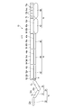
- FIG. 1 is a schematic perspective view showing an operating state of the supply device according to the first embodiment.
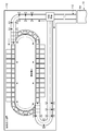
- FIG. 2 is a schematic view showing a state in which the supply device shown in FIG. 1 is viewed from above.
- FIG. 3 is a schematic view showing a state of a transport path along an extension direction in which the transport path of the supply device shown in FIGS. 1 and 2 extends.
- FIG. 4 is a schematic view showing an article sorting device that processes an object to be processed supplied from the supply device shown in FIG.
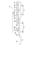
- FIG. 5 is a schematic view showing a state in which the supply device according to the second embodiment is viewed from above.
- FIG. 6 is a schematic view showing a state of a transport path along an extension direction in which the transport path of the supply device shown in FIG. 5 extends.
- the supply device (luggage supply device) 10 separates (separates) a multi-layered baggage, and for example, in a physical distribution system, the baggage is set at a predetermined time interval (predetermined pitch) with respect to a sorting device (logistics sorter) that classifies each destination. (Processing object) is supplied. Further, the supply device (parts supply device) 10 is located in, for example, a part of a production line, separates (separates) a large number of parts of the same type or different types (objects to be processed), and has a predetermined time interval (predetermined) for subsequent devices. Luggage (object to be processed) is supplied at (pitch).
- FIG. 1 is a schematic perspective view showing an operating state of the supply device 10.
- FIG. 2 is a schematic view showing a state in which the supply device 10 shown in FIG. 1 is viewed from above.
- the supply device 10 in FIG. 2 defines an XYZ Cartesian coordinate system.
- FIG. 3 shows a state in which the end portion in the width direction orthogonal to the extending direction of the transport path is viewed from the inside (other direction) to the outside (one direction). Therefore, FIG. 3 shows the case where it is assumed that the extension directions D (D10, D11, D12, D21, D22, D23, D31, D32) of the series of transport paths of the supply device 10 shown in FIG. 2 are straightened.
- It is a schematic diagram which shows the inclined state and the height difference of the transport path along the extension direction D.
- FIG. 4 is a schematic view showing an example of an article sorting device (distribution sorter) 110 that processes the processing object S supplied from the supply device 10.
- the supply device 10 includes a charging unit 12 into which a plurality of processing objects S are charged, a first transport unit 14, a second transport unit 16, and a third transport unit 18. Has.
- An example of the input unit 12 is a basket.
- a tipper containing a plurality of (many) processing objects S is tilted, and the plurality of processing objects S slide with respect to the tipper, so that the plurality of processing objects S are stored in the charging unit 12. Then, the object to be processed S placed on the charging section 12 comes into contact with, for example, the upstream end of the first transport path 14a.
- the upstream end of the transport path itself is the upstream end, and the downstream end is the downstream end.
- the first transport unit 14 has a first transport path 14a that transports the processing object S from the upstream side to the downstream side along the first transport direction C1 (C10, C11, C12).
- the extension directions D10, D11, and D12 of the first transport unit 14 are apparently straight along the X-axis direction as a whole, but as shown in FIG. 3, the extension direction D11 , D12 are tilted along the ZX plane with respect to the X-axis and the Z-axis.
- the extension directions D11 and D12 are inclined with respect to the horizontal plane (ground).
- the second transport section 16 is arranged on the downstream side of the first transport path 14a of the first transport section 14, and has, for example, a second transport path 16a bent into a U shape (including a J shape).
- the second transport path 16a of the second transport unit 16 transports the object S to be processed from the upstream side to the downstream side along the second transport directions C21, C22, and C23.
- the third transport unit 18 is arranged on the downstream side of the second transport path 16a, and has a third transport path 18a that transports the processing object S from the upstream side to the downstream side along the third transport direction C32.
- the third transport unit 18 is straight along the X-axis direction.
- the cargo loading unit 112 of the distribution sorter 110 of the distribution system shown in FIG. 4 is arranged on the downstream side of the third transport unit 18.
- a component input unit (not shown) of the production line may be arranged instead of the distribution sorter 110.
- the first transport unit 14 and the third transport unit 18 are separated from each other in the Y-axis direction. Therefore, the first transport unit 14 and the third transport unit 18 face each other with a space in between.
- the horizontal component of the first transport path 14a in the first transport direction C1 and the horizontal component of the third transport path 18a in the third transport direction C32 are straight.
- the horizontal component of the first transport direction C1 of the first transport path 14a and the horizontal component of the third transport direction C32 of the third transport path 18a are parallel (including substantially parallel) to each other and are directed in opposite directions.
- the first conveyor unit 14 is arranged on the downstream side of the first conveyor unit 22 along the X axis and the first conveyor unit (take-out conveyor unit) 22 adjacent to the downstream side of the loading unit 12. It has a second conveyor section 24.
- the first conveyor portion 22 has a transport path 22a horizontal to a horizontal plane (ground), for example, by an endless belt.
- the second conveyor portion 24 includes a first inclined conveyor (downward inclined conveyor portion) 32 having a transport path 32a that is inclined with respect to the horizontal plane as a downhill by an endless belt, and is inclined with respect to the horizontal plane as an uphill by, for example, an endless belt.
- It has a second inclined conveyor (upward inclined conveying portion) 34 having a conveying path 34a.
- the first inclined conveyor 32 is adjacent to the downstream side of the first conveyor portion 22.
- the second inclined conveyor 34 is adjacent to the downstream side of the first inclined conveyor 32.
- the first inclined conveyor (downward inclined conveying section) 32 is inclined downward along the first conveying direction C1 due to the downhill slope.
- the second inclined conveyor (upward inclined conveying section) 34 is inclined upward along the first conveying direction C1 due to the uphill slope.
- the transport speed V10 along the transport direction C10 of the transport path 22a of the first conveyor unit 22 is the same as or higher than the transport speed V11 along the transport direction C11 of the transport path 32a of the first inclined conveyor 32 of the second conveyor unit 24. Is also fast.
- the transport speed V12 along the transport direction C12 of the transport path 34a of the second inclined conveyor 34 of the second conveyor section 24 is the transport speed V11 along the transport direction C11 of the transport path 32a of the first inclined conveyor 32 of the second conveyor section 24. Same as or faster than that.
- the inclination angle ⁇ 1 of the transport path 32a of the first inclined conveyor 32 with respect to the horizontal plane shown in FIG. 3 is preferably, for example, about 10 ° to 40 °.
- the inclination angle ⁇ 2 of the transport path 34a of the second inclined conveyor 34 with respect to the horizontal plane is preferably, for example, about 10 ° to 40 °.
- the upstream end of the transport path 32a of the first inclined conveyor 32 is slightly lower between the downstream end of the transport path 22a of the first conveyor section 22 and the upstream end of the first inclined conveyor 32. In this case, the object S to be processed is easily delivered between the transport path 22a of the first conveyor section 22 and the transport path 32a of the first inclined conveyor 32.
- the second conveyor 16 has a first offset conveyor (first offset conveyor) 42 adjacent to the downstream side of the first conveyor 14 along the X-axis, and a second offset conveyor. It has a conveyor (second offset transport section) 44 and a third offset conveyor (third offset transport section) 46.
- the second conveyor 16 is connected with a plurality of conveyors (conveyors) 42, 44, 46 having different extension directions D21, D22, D23 and transport directions C21, C22, C23.
- the extension directions D21, D22, and D23 of the plurality of conveyors 42, 44, and 46 of the second conveyor 16 are U-shaped as a whole.
- the three conveyors 42, 44, and 46 may be arranged adjacent to each other, and it is not necessary to integrate them as one conveyor.
- the first one-sided conveyor 42 of the second transport unit 16 is installed on the downstream side of the first transport unit 14 along the first transport direction C1.
- the second one-sided conveyor 44 is installed on the downstream side of the first one-sided conveyor 42 along the direction intersecting with the first one-sided conveyor 42.
- the third one-sided conveyor 46 is installed on the downstream side of the second one-sided conveyor 44 along the direction intersecting with the second one-sided conveyor 44.
- the first offset conveyor 42 extends along the extension direction D21.
- the extension direction D21 of the first offset conveyor 42 substantially coincides with the horizontal component of the first transport direction C1.
- the transport path 42a of the first offset conveyor 42 is, for example, parallel to the XY plane.
- the transport direction C21 of the object S to be processed by the transport path 42a of the first offset conveyor 42 deviates from the horizontal component of the first transport direction C1.
- an oblique roller conveyor is used as the first offset conveyor 42.
- the transport direction C21 is inclined at an inclination angle ⁇ a with respect to the extension direction D21 of the transport path 42a of the first offset conveyor 42.
- the inclination angle ⁇ a is preferably, for example, about 10 ° to 40 °. Therefore, in the first offset conveyor 42, the processing object S placed on the transport path 42a of the first offset conveyor 42 is placed in one direction in the width direction orthogonal to the extension direction D21, that is, one end portion 42b. Can be brought to.
- the transport path 42a of the first offset conveyor 42 is set to the extension direction D21 of the first offset conveyor 42 at the speed of V21 ⁇ cos ⁇ a.
- the processing object S is moved along the line. It is preferable that the transport speed V21 along the transport direction C21 of the transport path 42a of the first offset conveyor 42 is higher than the transport speed V12 along the transport direction C12 of the transport path 34a of the second inclined conveyor 34.
- a first wall portion 52 serving as a wall is provided.
- the first wall portion 52 extends parallel to, for example, the extending direction D21 of the transport path 42a of the first offset conveyor 42. The presence of the first wall portion 52 prevents the object to be processed S from falling off from one end of the first offset conveyor 42 in one direction.
- the first wall portion 52 is an auxiliary conveyor portion that actively or passively conveys the object S to be processed along the first extension direction D21 from the upstream side to the downstream side of the transport path 42a of the first offset conveyor 42. It has 52a.
- the auxiliary transport portion 52a of the first wall portion 52 is directed to the other end portion (inner end portion) 42c in the width direction orthogonal to the extension direction D21 of the first offset conveyor 42.
- the auxiliary transport portion 52a of the first wall portion 52 actively transports the object S to be processed along the first extension direction D21 from the upstream side to the downstream side of the transport path 42a of the first offset conveyor 42. This will be described by taking the case of making the case as an example.
- the auxiliary transport unit 52a has an endless belt similar to that used in, for example, a belt conveyor.
- the normal direction of the transport surface 52b of the endless belt is, for example, horizontal and faces inward (other direction) in the width direction.
- the transport surface 52b of the endless belt of the auxiliary transport portion 52a operates so as to move the processing object S from the upstream side to the downstream side in parallel with the first extension direction D21, for example, at a speed of V21 ⁇ cos ⁇ a.
- a step H of, for example, about 10 cm is formed between the downstream end of the second inclined conveyor 34 and the upstream end of the first offset conveyor 42.
- the second offset conveyor 44 extends in a direction along the Y axis that is orthogonal to the extension direction D21 (direction along the X axis) of the first offset conveyor 42, for example.
- the transport path 44a of the second offset conveyor 44 is, for example, parallel to the XY plane.
- As the second offset conveyor 44 for example, an oblique roller conveyor is used.
- the transport direction C22 of the second offset conveyor 44 is inclined at an inclination angle ⁇ b with respect to the extension direction D22 of the second offset conveyor 44.
- the inclination angle ⁇ b is preferably, for example, about 10 ° to 40 °. Therefore, in the second offset conveyor 44, the processing object S placed on the transport path 44a of the second offset conveyor 44 is placed in one direction in the width direction orthogonal to the extension direction D22, that is, one end 44b. Can be brought to.
- the transport path 44a of the second offset conveyor 44 has a speed of V22 ⁇ cos ⁇ b ( ⁇ V21 ⁇ cos ⁇ a) and the second offset conveyor 44. It operates so as to move the processing object S along the extension direction D22 of. It is preferable that the transport speed V22 along the transport direction C22 of the transport path 44a of the second offset conveyor 44 is higher than the transport speed V21 along the transport direction C21 of the transport path 42a of the first offset conveyor 42.
- a second wall portion 54 serving as a wall is provided.
- the second wall portion 54 extends parallel to, for example, the extending direction D22 of the transport path 44a of the second offset conveyor 44. The presence of the second wall portion 54 prevents the object to be processed S from falling off from the second offset conveyor 44.
- the second wall portion 54 is an auxiliary conveyor portion that actively or passively conveys the object S to be processed along the second extension direction D22 from the upstream side to the downstream side of the transport path 44a of the second offset conveyor 44. It has 54a.
- the auxiliary transport portion 54a of the second wall portion 54 is directed to the other end portion (inner end portion) 44c in the width direction orthogonal to the extension direction D22 of the second offset conveyor 44.
- the auxiliary transport portion 54a of the second wall portion 54 actively transports the object S to be processed along the second extension direction D22 from the upstream side to the downstream side of the transport path 44a of the second offset conveyor 44. This will be described by taking the case of making the case as an example.
- the auxiliary transport portion 54a is formed in the same manner as, for example, the auxiliary transport portion 52a. Therefore, the transport surface 54b of the endless belt of the auxiliary transport portion 54a operates so as to move the processing object S from the upstream side to the downstream side in parallel with the second extension direction D22, for example, at a speed of V22 ⁇ cos ⁇ b.
- the third one-sided conveyor 46 is adjacent to the downstream side of the second one-sided conveyor 44 along the Y axis.
- the third offset conveyor 46 extends in a direction orthogonal to, for example, the extension direction D22 of the second offset conveyor 44.
- the transport path 46a of the third offset conveyor 46 is, for example, parallel to the XY plane.
- As the third offset conveyor 46 for example, an oblique roller conveyor is used.
- the transport direction C23 of the third offset conveyor 46 is inclined at an inclination angle ⁇ c with respect to the extension direction D23 of the third offset conveyor 46.
- the inclination angle ⁇ c is preferably, for example, about 10 ° to 40 °. Therefore, in the third offset conveyor 46, the processing object S placed on the transport path 46a of the third offset conveyor 46 is placed in one direction in the width direction orthogonal to the extension direction D23, that is, one end portion 46b. Can be brought to.
- the transport path 46a of the third one-sided conveyor 46 has a speed of V23 ⁇ cos ⁇ c ( ⁇ V22 ⁇ cos ⁇ b) and the third one-sided conveyor 46. It operates so as to move the processing object S along the extension direction D23 of. It is preferable that the transport speed V23 along the transport direction C23 of the transport path 46a of the third offset conveyor 46 is higher than the transport speed V22 along the transport direction C22 of the transport path 44a of the second offset conveyor 44.
- a third wall portion 56 that serves as a wall is provided.
- the third wall portion 56 extends parallel to, for example, the extending direction D23 of the transport path 46a of the third offset conveyor 46. The presence of the third wall portion 56 prevents the object to be processed S from falling off from the third offset conveyor 46.
- the third wall portion 56 is an auxiliary conveyor portion that actively or passively conveys the object S to be processed along the third extension direction D23 from the upstream side to the downstream side of the transport path 46a of the third offset conveyor 46. It has 56a.
- the auxiliary transport portion 56a of the third wall portion 56 is directed to the other end portion (inner end portion) 46c in the width direction orthogonal to the extension direction D23 of the third offset conveyor 46.
- the auxiliary transport portion 56a of the third wall portion 56 actively transports the object S to be processed along the third extension direction D23 from the upstream side to the downstream side of the transport path 46a of the third offset conveyor 46.
- the case of making the device will be described as an example.
- the auxiliary transport portion 56a is formed in the same manner as, for example, the auxiliary transport portions 52a and 54a. Therefore, the transport surface 56b of the endless belt of the auxiliary transport portion 56a moves the processing object S from the upstream side to the downstream side in parallel with the third extension direction D23, for example, at a speed of V23 ⁇ cos ⁇ c.
- the third conveyor 18 has a narrow conveyor 62, a speed governor 64, and a collection unit 66.
- a camera (sensor) (not shown) for recognizing, for example, the speed of the transport path 62a of the narrow conveyor 62 and the distance between the front and rear processing objects S on the transport path 62a is arranged in the third transport unit 18. ing.
- the narrow conveyor 62 is adjacent to the downstream side of the third offset conveyor 46 along the X axis.
- the upstream end of the narrow conveyor 62 is formed to have a width smaller than the width in the width direction orthogonal to the extension direction D23 of the downstream end of the third offset conveyor 46.
- the width of the narrow conveyor 62 is set according to, for example, the size of the object S to be processed.
- the narrow conveyor 62 has a width such that a plurality of objects S to be processed having an appropriate size are not lined up in the width direction.
- the narrow conveyor 62 has a transport path 62a horizontal to a horizontal plane (ground), for example by an endless belt.
- the upstream end of the transport path 62a of the narrow conveyor 62 is arranged at a position adjacent to the downstream end in one direction in the width direction of the transport path 46a of the third offset conveyor 46.
- the transport direction C31 of the narrow conveyor 62 is parallel to the extension direction D31 of the narrow conveyor 62. It is preferable that the transport speed V31 along the transport direction C31 of the transport path 62a of the narrow conveyor 62 is higher than the transport speed V23 along the transport direction C23 of the transport path 46a of the third offset conveyor 46.
- the object S to be processed falls off from one direction of the narrow conveyor 62 at the end (outer end) 62b in the width direction orthogonal to the extension direction D31 (conveyor direction C31) of the narrow conveyor 62.
- a fourth wall portion 68 is provided as a wall for preventing the above.
- the fourth wall portion 68 extends parallel to, for example, the extending direction D31 of the transport path 62a of the narrow conveyor 62. The presence of the fourth wall portion 68 prevents the object to be processed S from falling off from the narrow conveyor 62.
- end portion (outer end portion) 62b of the narrow conveyor 62 and the end portion (outer end portion) 46b of the third offset conveyor 46 are in a straight line along the X axis.
- the fourth wall portion 68 has an auxiliary transport portion 68a that actively or passively transports the object S to be processed along the extension direction D31 from the upstream side to the downstream side of the transport path 62a of the narrow conveyor 62. ..
- the auxiliary transport portion 68a of the fourth wall portion 68 is directed to the other end portion (inner end portion) 62c in the width direction orthogonal to the extension direction D31 of the narrow conveyor 62.
- the auxiliary transport portion 68a is formed in the same manner as, for example, the auxiliary transport portions 52a, 54a, 56a. Therefore, the transport surface 68b of the endless belt of the auxiliary transport portion 68a moves the processing object S parallel to the extension direction D31, for example, from the upstream side to the downstream side at a speed V31.
- the horizontal component of the first transport direction C1 of the first transport path 14a and the horizontal component of the third transport direction C32 of the third transport path 18a are straight.
- the speed governor 64 is adjacent to the downstream side of the narrow conveyor 62 along the X axis.
- the transport path 64a of the speed governor 64 appropriately accelerates and decelerates with respect to the transport speed of the transport path 62a of the narrow conveyor 62 so that the objects S placed on the transport path 64a are separated from each other at a predetermined pitch. Be controlled.
- the upstream end of the speed governor 64 is formed to have substantially the same width as the width in the width direction orthogonal to the extension direction D31 of the downstream end of the narrow conveyor 62.
- the transport path 64a of the speed governor 64 is horizontal to a horizontal plane (ground), for example, by an endless belt.
- the transport direction C32 of the speed governor 64 is parallel to the extension direction D32 of the speed governor 64.
- the transport speed V32 along the transport direction C32 of the transport path 64a of the speed governor 64 is controlled so as to separate the pitches of the processing objects S arranged in a row from each other to a predetermined pitch. Therefore, the transfer speed V32 along the transfer direction C32 of the transfer path 64a of the speed governor 64 can be increased or decreased.
- the object S to be processed falls off from one direction of the speed governor 64 at the end (outer end) 64b in the width direction orthogonal to the extension direction D32 (conveyor direction C32) of the speed governor 64.
- a fifth wall portion 70 is provided as a wall for preventing the above.
- the fifth wall portion 70 extends parallel to, for example, the extension direction D32 of the transport path 64a of the speed governor 64. The presence of the fifth wall portion 70 prevents the object S to be processed from falling off from the speed governor 64.
- end portion (outer end portion) 64b of the speed governor 64 and the end portion (outer end portion) 62b of the narrow conveyor 62 are in a straight line along the X axis.
- the fifth wall portion 70 has an auxiliary transport portion 70a that actively or passively transports the object S to be processed along the extension direction D32 from the upstream side to the downstream side of the transport path 64a of the speed governor 64. ..
- the auxiliary transport portion 70a of the fifth wall portion 70 is directed to the other end portion (inner end portion) 64c in the width direction orthogonal to the extension direction D32 of the speed governor 64.
- the auxiliary transport unit 70a may be formed as a transport surface for actively transporting the object S to be processed, as in the transport surfaces 52b, 54b, 56b, 68b of the auxiliary transport portions 52a, 54a, 56a, 68a, for example.
- the auxiliary transport unit 70a has a plurality of rollers 70b that passively rotate when the object to be processed S comes into contact with the auxiliary transport unit 70a.
- the rollers 70b in FIG. 3 are arranged, for example, in a grid pattern or in a row.
- Each of the rollers 70b is formed in a spherical shape, and can freely rotate at that position.
- the roller 70b may be formed so as to rotate around an axis parallel to the Z axis, like a roller (wheel) of a roller conveyor.
- the collection unit 66 is adjacent to the downstream end of the third conveyor 46 of the second conveyor 16 along the X axis of the transport path 46a, and is adjacent to the other direction (inside) in the width direction of the narrow conveyor 62.
- the recovery unit 66 has an inclined surface 72 and a guide 74.
- the inclined surface 72 is formed as a flat surface or a curved surface.
- the inclined surface 72 is higher as it is closer to the narrow conveyor 62 (first end 72a), and is closer to the other in the width direction orthogonal to the horizontal component of the first conveyor 14 in the transport direction C1 (second end 72b). ) Is as low as possible.
- the inclined surface 72 is higher at a position closer to the downstream end of the transport path 46a of the third offset conveyor 46 (third end 72c), and is separated from the downstream end of the transport path 46a of the third offset conveyor 46 along the X-axis direction. The lower the position (4th end 72d).
- the object to be processed S placed on the inclined surface 72 slides toward the fourth end portion 72d of the inclined surface 72 due to its own weight.
- the first end 72a of the inclined surface 72 on the narrow conveyor 62 side may be continuous with the downstream end of the narrow conveyor 62 transport path 62a, and may have a step at the downstream end of the narrow conveyor 62 transport path 62a. It may be located on the lower side.
- the guide 74 is formed in a plate shape.
- the guide 74 is fixed to the second end portion 72b of the inclined surface 72.
- the guide 74 extends along the X-axis direction.
- the guide 74 is formed so as to project upward from the second end portion 72b (the end portion of the first transport portion 14 that is close to the other in the width direction orthogonal to the horizontal component of the transport direction C1) of the inclined surface 72. There is.
- the supply device 10 puts the processing object S collected by the collecting unit 66 into the charging unit 12 adjacent to the collecting unit 66 that collects the processing object S in the third transport unit 18. It has a fourth transport unit 20 for transporting toward.
- the fourth transport unit 20 has, for example, a curve conveyor 92.
- the curve conveyor 92 is provided between the fourth end portion 72d and the charging portion 12 of the inclined surface 72 of the collecting portion 66.
- the upstream end of the transport path 92a of the curve conveyor 92 is adjacent to the fourth end 72d of the inclined surface 72.
- the downstream end of the transport path 92a of the curve conveyor 92 is adjacent to the charging section 12.
- the lengths of the first conveyor 42, the second conveyor 44, and the third conveyor 46 of the second conveyor 16 along the extension directions D21, D22, and D23 are orthogonal to the extension directions D21, D22, and D23.
- the widths and angles ⁇ a, ⁇ b, and ⁇ c are such that, for example, the processing object S at the inner end 42c of the downstream end of the transport path 42a of the first conveyor 42 has the first conveyor 42 and the second conveyor 42 as described later. It is set so that when it passes through the conveyor 44 and the third offset conveyor 46, it comes into contact with the outer end portion 46b of the third offset conveyor 46.
- the transport speed of the first transport unit 14 along the first transport direction C1 (C10, C11, C12) is assumed to match the moving speed of the processing object S in contact with the first transport unit 14. ..
- the transport speed of the second transport unit 16 along the second transport directions C21, C22, and C23 comes into contact with the second transport unit 16 in a state where the object S to be processed does not contact the wall portions 52, 54, 56. It is assumed that it matches the moving speed of the processing object S.
- the transport speed of the third transport unit 18 along the third transport directions C31 and C32 is the transport speed of the processing target S that comes into contact with the third transport unit 18 when the processing object S does not touch the wall portions 68 and 70. It shall match.
- the tipper is tilted and the object S to be processed is charged into the charging unit 12.
- the employee may input the processing object S into the input unit 12.
- the objects S to be processed which may be in a multi-layered bulk state in the loading section 12, are sequentially upstream of the transport path 22a of the first conveyor section 22 of the first transport section 14 due to, for example, the inclination of the floor surface of the loading section 12. Move towards the edge.
- the first conveyor unit 22 of the first conveyor unit 14 takes out the processing target object S in contact with the transport path 22a by the transfer operation of the transfer path 22a, and moves the plurality of processing objects S in the transfer direction C10. Separate and disperse.
- the object S to be processed which is in contact with the transport path 22a of the first conveyor section 22, is conveyed from the upstream side to the downstream side.
- the other processing target S stacked on the upper side of the processing target S is on the lower side according to the frictional force with the lower processing target S. Slip against the object S to be processed. Therefore, a part of the multi-layered object S to be processed is destroyed. In this way, for example, a part of the processing object S having a plurality of layers is separated and separated.
- the object S to be processed is delivered from the transport path 22a of the first conveyor section 22 to the transport path 32a of the first inclined conveyor 32 of the second conveyor section 24.
- the transport path 32a of the first inclined conveyor 32 is inclined as a downhill.
- the processing object S placed on the upper side of the rectangular parallelepiped processing object S in contact with the transport path 32a of the first inclined conveyor 32 is acted on by a component that inclines in the horizontal direction parallel to the upper surface of the processing object S. .. Therefore, the other processing object S stacked on the upper side of the processing object S in contact with the transport path 32a is in the transport path 32a as compared with the case where it is horizontal as in the transport path 22a of the first conveyor unit 22. It is slippery with respect to the object S in contact with it.
- the transport speed V11 of the transport path 32a of the first inclined conveyor 32 is lower than the transport speed V10 of the transport path 22a of the first conveyor unit 22. Therefore, due to the difference in transport speed between the horizontal transport path 22a of the first conveyor portion 22 and the transport path 32a of the first inclined conveyor 32, the processing object S in contact with the transport path 32a is in a state of being braked and transported.
- the processing object S on the upper side of the processing object S in contact with the path 32a slides with respect to the processing object S in contact with the transport path 32a according to the law of inertia, and the multilayer processing object S is broken.
- the multi-layered object S to be processed is broken in the first inclined conveyor 32. Therefore, for example, a part of the processing object S having a plurality of layers is separated and separated.
- the processing object S in contact with the transport path 32a of the first inclined conveyor 32 rolls and becomes a plurality of layers such as two layers.
- the object S to be processed is destroyed.
- a part of the object S to be processed is delivered from the transport path 32a of the first inclined conveyor 32 of the second conveyor section 24 to the transport path 34a of the second inclined conveyor 34 of the second conveyor section 24, for example, in a state of a plurality of layers. ..
- the transport path 34a of the second inclined conveyor 34 is inclined as an uphill. Therefore, the other processing object S stacked on the upper side of the processing object S in contact with the transfer path 34a is in the transfer path 34a as compared with the case where it is horizontal as in the transfer path 22a of the first conveyor unit 22. It is slippery with respect to the object S in contact with it.
- the transfer speed V12 of the transfer path 34a of the second inclined conveyor 34 is higher than the transfer speed V11 of the transfer path 32a of the first inclined conveyor 32. Therefore, due to the difference in transfer speed between the transfer path 32a of the first inclined conveyor 32 and the transfer path 34a of the second inclined conveyor 34, the processing object S in contact with the transfer path 34a is in a state of being accelerated and is in contact with the transfer path 34a.
- the processing object S on the upper side of the processing object S slides on the processing object S in contact with the transport path 34a according to the law of inertia, and the multi-layered processing object S is broken.
- the multi-layered object S to be processed is further destroyed in the second inclined conveyor 34. Therefore, for example, a part of the processing object S having a plurality of layers is separated and separated.
- first conveyor section 22 and the second conveyor section 24 break the multi-layered object S to be processed and separate it one by one.
- These multilayer processing objects S may be parts of the same type or parts of different types.
- the object S to be processed is delivered from the second inclined conveyor 34 to the first offset conveyor 42. Due to the step H between the second inclined conveyor 34 and the first offset conveyor 42, the object S to be processed moves significantly when it is passed from the second inclined conveyor 34 to the first offset conveyor 42. At this time, the object to be processed S is separated by pulling the object to be processed by the first offset conveyor 42 on the downstream side of the second inclined conveyor 34 so as to take out the object to be processed along the transport direction C21.
- FIG. 3 an example in which a step H is provided between the second inclined conveyor 34 and the first offset conveyor 42 is shown.
- a conveyor having a horizontal transfer path is arranged between the second inclined conveyor 34 and the first one-sided conveyor 42, and there is a step H between the conveyor having the horizontal transfer path and the first one-sided conveyor 42. May be good.
- the objects S to be processed which are separated one by one, incline with respect to the extension direction D21 of the first one-sided conveyor 42 from the upstream side to the downstream side on the transport path 42a of the first one-sided conveyor 42. It moves in the transport direction C21. Therefore, the plurality of objects S to be processed are offset toward the first wall portion 52 on the transport path 42a of the first offset conveyor 42. Therefore, the distance in the width direction of the plurality of objects S to be processed is gradually narrowed from the upstream side to the downstream side. Then, a part of the object S to be processed comes into contact with the first wall portion 52 between the upstream end and the downstream end of the transport path 42a of the first offset conveyor 42.
- the object S to be processed which is in contact with the first wall portion 52 on the transport path 42a of the first one-sided conveyor 42, moves in the direction along the extension direction D21 of the transport path 42a at a speed of V21 ⁇ cos ⁇ a.
- the object S to be processed moves along the first wall portion 52 and is delivered from the transport path 42a of the first one-sided conveyor 42 to the transport path 44a of the second one-sided conveyor 44. Therefore, the auxiliary transport portion 52a of the first wall portion 52 prevents the first wall portion 52 from hindering the movement of the processing object S when the processing object S comes into contact with the first wall portion 52. do.
- the object S to be processed moves on the transport path 44a of the second offset conveyor 44 in the transport direction C22 which is inclined with respect to the extension direction D22 of the second offset conveyor 44 from the upstream side to the downstream side.
- the transport direction of the object S to be processed is changed from the direction along the extension direction D21 or the direction along the transport direction C21 to the direction along the transport direction C22. Therefore, the plurality of objects S to be processed are offset toward the second wall portion 54 on the transport path 44a of the second offset conveyor 44. Therefore, the distance in the width direction of the plurality of objects S to be processed is gradually narrowed.
- the object S to be processed which is in contact with the second wall portion 54 on the transport path 44a of the second offset conveyor 44, moves in the direction along the extension direction D22 of the transport path 44a at a speed of V22 ⁇ cos ⁇ b.
- the object S to be processed moves along the second wall portion 54 and is delivered from the transport path 44a of the second offset conveyor 44 to the transport path 46a of the third offset conveyor 46. Therefore, the auxiliary transport portion 54a of the second wall portion 54 prevents the second wall portion 54 from hindering the movement of the processing object S when the processing object S comes into contact with the second wall portion 54. do.
- the object S to be processed moves on the transport path 46a of the third one-sided conveyor 46 in the transport direction C23 that is inclined with respect to the extension direction D23 of the third one-sided conveyor 46 from the upstream side to the downstream side.
- the transport direction of the object S to be processed is changed from the direction along the extension direction D22 or the direction along the transport direction C22 to the direction along the transport direction C23. Therefore, the plurality of objects S to be processed are offset toward the third wall portion 56 on the transport path 46a of the third offset conveyor 46. Therefore, the distance in the width direction of the plurality of objects S to be processed is gradually narrowed. Then, a part of the object S to be processed comes into contact with the third wall portion 56 between the upstream end and the downstream end of the transport path 46a of the third offset conveyor 46.
- the plurality of processing objects S transported along the center of the transport path 14a of the first transport section 14 in the width direction are the transport path 42a of the first one-sided conveyor 42 and the transport path 44a of the second one-sided conveyor 44.
- the side-by-side state orthogonal to the extension directions D21, D22, and D23 gradually disappears as the conveyor moves to the transport path 46a of the third offset conveyor 46, that is, the direction is changed.
- the plurality of objects S to be processed are arranged in a row, for example, in the transport path 46a of the third offset conveyor 46.
- the second transport unit 16 shifts the plurality of objects S to be processed in one direction in the width direction orthogonal to the extension directions D21, D22, and D23 of the U-shaped second transport path 16a as a whole. While arranging in a row.
- the object S to be processed which is in contact with the third wall portion 56 on the transport path 46a of the third one-sided conveyor 46, moves in the direction along the extension direction D23 of the transport path 46a at a speed of V23 ⁇ cos ⁇ c.
- the object S to be processed moves along the third wall portion 56 and is delivered from the transport path 46a of the third one-sided conveyor 46 to the transport path 62a of the narrow conveyor 62. Therefore, the auxiliary transport portion 56a of the third wall portion 56 prevents the third wall portion 56 from hindering the movement of the processing object S when the processing object S comes into contact with the third wall portion 56. do.
- the transport speed V31 of the transport path 62a of the narrow conveyor 62 is higher than V23 ⁇ cos ⁇ c. Therefore, when the conveyor is delivered from the conveyor 46a of the third one-sided conveyor 46 to the conveyor 62a of the narrow conveyor 62, the conveyor 62a of the narrow conveyor 62 is a plurality of objects S arranged in a row. Widen the pitch.
- the object S to be processed which is in contact with the fourth wall portion 68 on the transport path 62a of the narrow conveyor 62, moves in the direction along the predetermined transport direction C31 (extension direction D31) of the transport path 62a at the speed of V31. do.
- the object S to be processed moves along the fourth wall portion 68 and is delivered from the transport path 62a of the narrow conveyor 62 to the transport path 62a of the narrow conveyor 62. Therefore, the auxiliary transport portion 68a of the fourth wall portion 68 prevents the fourth wall portion 68 from hindering the movement of the processing object S when the processing object S comes into contact with the fourth wall portion 68. do.
- the transport speed V32 of the transport path 64a of the speed governor 64 of the third transport unit 18 is appropriately controlled based on the information of the processing objects S before and after the above. That is, the speeding up and deceleration of the transport speed V32 along the predetermined transport direction C32 (extending direction D32) of the transport path 64a of the speed control conveyor 64 of the third transport unit 18 is controlled, and the speed of the third transport unit 18 is adjusted.
- the processing objects S arranged in a row are separated from each other at a predetermined pitch.
- the processing objects S arranged in a row separated by a predetermined pitch are put into the cargo loading section 112 of the logistics sorter 110 of the logistics system on the downstream side of the third transport section 18.
- the processing objects S arranged in a row at a predetermined pitch are charged into the component charging section of the production line on the downstream side of the third transport section 18.
- the roller 70b of the auxiliary transport unit 70a rotates at that position and is parallel to the extension direction D32, and the speed control conveyor of the third transport unit 18 is used.
- the object S to be processed is moved from the upstream side to the downstream side at the speed V32 of the transport path 64a of 64. Therefore, the auxiliary transport portion 70a of the fifth wall portion 70 prevents the friction between the fifth wall portion 70 and the processing object S from hindering the movement of the processing object S.
- a plurality of objects S to be processed are not arranged in a row, and in the transport path 46a of the third offset conveyor 46, the width orthogonal to the extension direction D23 of the third offset conveyor 46. May be lined up in a direction.
- the processing object S that was not arranged in a row in the transport path 46a of the third one-sided conveyor 46 the processing object S that is separated from the third wall portion 56 in the width direction is the transport path of the third one-sided conveyor 46. It is not conveyed from the downstream end of 46a to the transport path 62a of the narrow conveyor 62, but is delivered to the inclined surface 72 of the fourth conveyor 20. Therefore, the object S to be processed reaches the fourth end portion 72d of the inclined surface 72 while sliding near the boundary between the inclined surface 72 and the guide 74.
- the processing object S that has reached the fourth end portion 72d of the inclined surface 72 is conveyed to the charging portion 12 by the curve conveyor 92.
- the collection unit 66 and the fourth transport unit 20 direct the processing target S, which has failed to be offset in one direction in the second transport unit 16 among the processing objects S, toward the first transport unit 14.
- Transport Therefore, the collection unit 66 can collect a part of the processing object S that is offset in one direction by the second transport unit 16 among the processing objects S. Therefore, the processing object S collected by the collection unit 66 and transported from the fourth transport unit 20 to the loading unit 12 is again transported from the loading unit 12 to the first transport unit 14, the second transport unit 16, and the third transport unit. It is arranged at a predetermined pitch with respect to other objects S to be processed through the unit 18, and is charged into the cargo loading unit 112 of the distribution sorter 110 of the distribution system and the parts input unit of the production line.
- the first transport unit 14 of the supply device 10 is used as a separate stage for separating the plurality of objects S to be processed, which are piled up in bulk, one by one.
- the second transport unit 16 is used as an arrangement stage for arranging the processing objects S separated from each other in a row.
- the third transport unit 18 is used as an adjusting stage that separates the processing objects S arranged in one row at a predetermined pitch. Then, the supply device 10 according to the present embodiment transfers a plurality of processing objects S to the first transport unit (separate stage) 14, the second transport unit (arrange stage) 16, and the third transport unit (adjustment stage) 18. It can be transported in order and delivered to other devices.
- the processing target object S is separated by the first transport unit 14.
- the processing objects S are arranged as an example, and in a state where the processing objects S are separated from each other at a predetermined pitch in the third transport unit 18, the load loading unit 112 of the distribution sorter 110 and the production line It can be put into the parts putting part of. Therefore, the processing objects S charged into the charging unit 12 are automatically separated by the supply device 10 by the first transport unit 14, the second transport unit 16, and the third transport unit 18, arranged in a line, and predetermined. The pitch can be spaced. Then, the processing object S can be delivered from the supply device 10 to the subsequent device.
- the bulk-loaded processing objects S use a first conveyor unit 22 and a plurality of conveyor units such as the first inclined conveyor 32 and the second inclined conveyor 34 of the second conveyor unit 24. It can be separated one by one. Therefore, in the second transport unit 16, it is possible to avoid a state in which the objects to be processed S have multiple layers. Therefore, it is easy to arrange a plurality of processing objects S in one row.
- the processing object S having a different size, material, and shape is input to the first transport unit 14 regardless of whether the processing object S is different or the same type.
- the objects S to be processed can be separated from each other at a predetermined pitch and delivered to another device.
- the supply device 10 according to the present embodiment appropriately forms a transport path 16a of the second transport unit 16 to appropriately form a relatively small object S such as a bolt or nut, a beverage bottle larger than the bolt or nut, or the like. It is possible to deal with the processing object S and even a relatively large processing object S such as a home delivery.
- the object S to be processed is greatly moved when it is passed from the second inclined conveyor 34 to the first offset conveyor 42. Is done. Therefore, the object to be processed S can be separated by pulling the object to be processed by the first offset conveyor 42 on the downstream side of the second inclined conveyor 34 so as to take out the object to be processed along the transport direction C21.
- the transfer speed V12 of the transfer path 32a of the second inclined conveyor 34 of the first transfer unit 14 is transferred to the transfer path 42a of the first offset conveyor 42 of the second transfer unit 16.
- the speed V21 is increased to increase the transfer speed V22 of the transfer path 44a of the second offset conveyor 44 with respect to the transfer speed V21 of the transfer path 42a of the first offset conveyor 42, and the transfer speed V22 of the transfer path 44a of the second offset conveyor 44 is increased.
- the transport speed V23 of the transport path 46a of the third one-sided conveyor 46 is increased with respect to the speed V22, and the transport speed V31 of the transport path 62a of the narrow conveyor 62 is increased with respect to the transport speed V23 of the transport path 46a of the third one-sided conveyor 46.
- the transport paths 32a, 42a, 44a, 46a, 62a are delivered to each other, a distance can be taken between the processing objects S along the transport direction due to the speed difference. Therefore, it is possible to prevent the object S to be processed from staying on the transfer path 16a of the second transfer unit 16 and to separate the object S to be processed. Therefore, it is possible to prevent the objects S to be processed from interfering with each other, and the objects S to be processed are likely to be arranged in a row on the transport path 46a.
- the supply device 10 includes a plurality of conveyors 42, 44, 46 in which the extension directions D21, D22, D23 of the second transport unit 16 are U-shaped as a whole.
- the extension directions D21, D22, D23 of these plurality of conveyors 42, 44, 46 are, for example, straight. Therefore, the cost increase can be suppressed as compared with the case where the conveyors 42, 44, and 46 are integrally formed according to the space.
- the first transport unit 14 on the upstream side of the second transport unit 16 and the first transport unit 14 on the downstream side of the second transport unit 16 3 It is easy to arrange the transport unit 18 so as to face each other in the Y-axis direction. Further, the horizontal components of the extension directions D10, D11, and D12 of the first transfer unit 14 are parallel to the extension direction D31 of the narrow conveyor 62 of the third transfer unit 18 and the extension direction D32 of the speed governor 64. can do. Therefore, the supply device 10 according to the present embodiment can be arranged in a space-saving manner.
- the supply device 10 is formed according to the installation space. be able to.
- the lengths of the extension directions D21, D22, D23 of the plurality of conveyors 42, 44, 46, the width orthogonal to the extension directions D21, D22, D23, and the inclination angles ⁇ a, ⁇ b, ⁇ c of the conveyors 42, 44, 46. Can be appropriately set to appropriately set the size, shape, and the like of the second conveyor 16.
- the narrow conveyor 62 of the third transport unit 18 uses an endless belt.
- ball rollers arranged in a grid pattern may be used.
- the object S to be processed placed on the narrow conveyor 62 can be pushed out from the wall portion 68 to the collection portion 66. Therefore, the collection unit 66 can collect a part of the processing object S that is offset in one direction by the second transport unit 16 among the processing objects S.
- the supply device 10 can selectively convey, for example, the same type of processing object S or the processing object S having the same size to the third transport unit 18.
- the second conveyor 16 has a narrow conveyor 62.
- a roller conveyor (not shown) having a width similar to that of the third offset conveyor 46 and parallel to the extension direction D32, which is the same as the third conveyor 18, is used. You may.
- a gate may be provided between the end of the third offset conveyor 46 and the roller conveyor arranged on the downstream side of the third offset conveyor 46. By opening and closing the gate, or by detecting the processing object S at the gate, it is possible to sort whether or not the processing object S is transported to the third transport unit 18.
- the gate may be provided on the transport path 64a of the speed governor 64 of the third transport unit 18.
- the transport speed of the transport path 64a of the speed control conveyor 64 of the third transport unit 18 is set to a constant speed, the timing of passing through the gate is adjusted by opening and closing the gate, and the distance between the objects S to be processed is separated by a predetermined distance. be able to.
- the third conveyor 18 has a narrow conveyor 62.
- the object S to be processed may be delivered from the third offset conveyor 46 to the speed governor 64 of the third conveyor 18, for example, by suction by a robot arm.
- a robot arm may be used instead of the transport path 18a of the third transport unit 18.
- the third transport unit 18 may be a robot.
- the processing object S transported to the downstream end of the third offset conveyor 46 of the second transport unit 16 by the arm of the robot is transferred to, for example, the cargo loading unit 112 of the distribution sorter 110 of the distribution system or the parts input unit of the production line. You may put it directly in.
- a collection container (not shown) that collects the processing objects S that are not lined up in one direction in the second conveyor 16 is provided. It may be arranged at the downstream end of the third offset conveyor 46 of the second transport unit 16 at a position adjacent to the narrow conveyor 62 of the third transport unit 18. After collecting the processing objects S in the collecting container as the collecting unit 66 for an appropriate time, the collecting container may be moved to recharge each processing object S into the charging unit 12. Therefore, the fourth transport unit 20 is not always necessary.
- the fourth conveyor 20 can use, for example, a straight conveyor or a vertical conveyor instead of the curved conveyor 92.
- the position of the upstream end of the fourth conveyor 20 is a position adjacent to the speed governor 64 in FIG.
- the position of the upstream end of the fourth conveyor 20 may be a position adjacent to the narrow conveyor 62.
- first wall portion 52, the second wall portion 54, the third wall portion 56, and the fourth wall portion 68 have auxiliary transport portions 52a, 54a, 56a, 68a that actively move has been described.
- the first wall portion 52, the second wall portion 54, the third wall portion 56, and the fourth wall portion 68 may be configured to passively transport the object S to be processed from the upstream side to the downstream side.
- the first wall portion 52, the second wall portion 54, the third wall portion 56, and the fourth wall portion 68 passively transport the object S to be processed from the upstream side to the downstream side, for example, the auxiliary transport unit. It is preferable that the configuration is the same as that of 70a.
- All auxiliary transport units 52a, 54a, 56a, 68a, 70a may be configured to actively transport the processing object S from the upstream side to the downstream side. All auxiliary transport units 52a, 54a, 56a, 68a, 70a passively operate according to the transport of the processing object S in the adjacent transport paths 42a, 44a, 46a, 62a, 64a, and move from the upstream side to the downstream side. It may be configured to be transported.
- a supply device 10 that facilitates handling of a processing object S in a multi-layered bulk state or the like in a subsequent device such as a distribution sorter 110 or a production line. ..
- FIG. 5 is a schematic view showing a state in which the supply device 10 according to the present embodiment is viewed from above.
- the supply device 10 in FIG. 5 defines an XYZ Cartesian coordinate system.
- FIG. 6 shows a state in which the end portion in the width direction orthogonal to the extending direction of the transport path is viewed from the inside (other direction) to the outside (one direction). Therefore, FIG. 6 is a schematic diagram showing a transport path when it is assumed that the extension directions D (D101, D201, D202, D31, D32) of the series of transport paths of the supply device 10 shown in FIG. 5 are straightened. It is a figure.
- the first transport unit 14 has a first transport path 14a for transporting the processing object S from the upstream side to the downstream side along the first transport direction C101.
- the extension direction D101 of the first transport unit 14 is straight along the X-axis direction.
- the first conveyor unit 14 uses, for example, a vibration conveyor (vibration feeder) instead of using the first conveyor unit 22 and the second conveyor unit 24 described in the first embodiment.
- a vibration conveyor vibration feeder
- the second transport unit 16 has a second transport path 16a bent in an L shape.
- the second transport path 16a of the second transport unit 16 transports the object S to be processed from the upstream side to the downstream side along the second transport directions C201 and C202.
- the horizontal components of the first transport direction C1 of the first transport path 14a and the horizontal components of the third transport directions C31 and C32 of the third transport path 18a are straight. Is.
- the horizontal components of the first transport direction C1 of the first transport path 14a and the horizontal components of the third transport directions C31 and C32 of the third transport path 18a are parallel to each other (including substantially parallel) and are directed in opposite directions.
- the first transport unit 14 and the third transport unit 18 are displaced in the X-axis direction, but may face each other in the Y-axis direction depending on the width and size of each conveyor.
- the second conveyor 16 is aligned with the first roller conveyor (conveyor) 402 adjacent to the downstream side along the X axis of the first conveyor 14 and the Y axis of the first roller conveyor 402. It has a second roller conveyor (conveyor unit) 404 adjacent to the downstream side, and a guide 406 provided on the transport path 402a of the first roller conveyor 402 and on the transport path 404a of the second roller conveyor 404.
- a plurality of conveyors (conveyor units) 402 and 404 are connected to each other with different extension directions D201 and D202 and transfer directions C201 and C202.
- the extension directions D201 and D202 of the plurality of conveyors 402 and 404 of the second conveyor 16 are L-shaped as a whole.
- the two conveyors 402 and 404 may be arranged adjacent to each other, and need not be integrated as one conveyor.
- the first roller conveyor 402 of the second conveyor 16 is installed on the downstream side of the first conveyor 14 along the direction intersecting the first conveyor 14.
- the second roller conveyor 404 is installed on the downstream side of the first roller conveyor 402 along the direction intersecting with the first roller conveyor 402.
- the transport path 402a of the first roller conveyor 402 is, for example, parallel to the XY plane.
- the transport path 404a of the second roller conveyor 404 is, for example, parallel to the XY plane.
- the extension direction D201 of the first roller conveyor 402 and the transport direction of the transport path 402a of the first roller conveyor 402 are parallel.
- the extension direction D202 of the second roller conveyor 404 and the transfer direction of the transfer path 404a of the second roller conveyor 404 are parallel.
- the extension direction D201 of the first roller conveyor 402 and the extension direction D202 of the second roller conveyor 404 are, for example, orthogonal to each other.
- a first wall portion 502 serving as a wall is provided.
- the first wall portion 502 extends parallel to, for example, the extending direction D201 of the transport path 402a of the first roller conveyor 402. The presence of the first wall portion 502 prevents the object S to be processed from falling off from the unidirectional end portion 402b of the first roller conveyor 402.
- the first wall portion 502 is an auxiliary conveyor portion that actively or passively conveys the object S to be processed along the first extension direction D201 from the upstream side to the downstream side of the transport path 402a of the first roller conveyor 402. It has 502a.
- the auxiliary transport portion 502a of the first wall portion 502 is directed to the other end (inner end) 402c in the width direction orthogonal to the extension direction D201 of the first roller conveyor 402.
- the auxiliary transport portion 502a of the first wall portion 502 has, for example, a plurality of rollers 502b that passively rotate when the object S to be processed comes into contact with the auxiliary transport portion 502a.
- Each of the rollers 502b in FIG. 6 is formed in a spherical shape and can rotate freely at that position.
- a second wall portion 504 that serves as a wall is provided.
- the second wall portion 504 extends parallel to, for example, the extending direction D202 of the transport path 404a of the second roller conveyor 404. The presence of the second wall portion 504 prevents the object S to be processed from falling off from the unidirectional end portion 404b of the second roller conveyor 404.
- the second wall portion 504 is an auxiliary conveyor portion that actively or passively conveys the object S to be processed along the second extension direction D202 from the upstream side to the downstream side of the transport path 404a of the second roller conveyor 404. It has a 504a.
- the auxiliary transport portion 504a of the second wall portion 504 is directed to the other end (inner end) 404c in the width direction orthogonal to the extension direction D202 of the second roller conveyor 404.
- the auxiliary transport portion 504a of the second wall portion 504 has, for example, a plurality of rollers 504b that passively rotate when the object S to be processed comes into contact with the auxiliary transport portion 504a.
- Each of the rollers 504b in FIG. 6 is formed in a spherical shape and can rotate freely at that position.
- the second wall portion 504 also extends to the end portion (outer end portion) 62b of the narrow conveyor 62.
- the auxiliary transport portion 504a of the second wall portion 504 is directed to the other end (inner end) 62c in the width direction orthogonal to the extension direction D31 of the narrow conveyor 62.
- the extension line L is the second guide described later. It is preferable to intersect the guide surface 409a of the rod 409.
- the guide 406 has a first guide rod 407 and a second guide rod 409 in this embodiment.
- the first guide rod 407 has a guide surface 407a that is inclined with respect to the extension direction D201 of the first roller conveyor 402 on the transport path 402a of the first roller conveyor 402.
- the first guide rod 407 is fixed to, for example, the end portion 402c.
- the guide surface 407a of the first guide rod 407 is directed to the end portion 402b in the width direction orthogonal to the extension direction D201.
- the guide surface 407a goes from the end portion 402c to the end portion 402b from the upstream side to the downstream side.
- the guide surface 407a is separated from the end portion 402b by a distance through which the object S to be processed can pass.
- the second guide rod 409 has a guide surface 409a that is inclined with respect to the extension direction D202 of the second roller conveyor 404 on the transport path 404a of the second roller conveyor 404.
- the second guide rod 409 is fixed to, for example, the end 404c.
- the guide surface 409a of the second guide rod 409 is directed to the unidirectional end 404b in the width direction orthogonal to the extension direction D202.
- the guide surface 409a goes from the end 404c to the end 404b from the upstream side to the downstream side.
- the guide surface 409a is separated from the end portion 404b by a distance through which the object S to be processed can pass.
- the object S to be processed in the multi-layered bulk state is sequentially directed toward the upstream end of the transport path 22a of the first conveyor section 22 of the first transport section 14 due to the inclination of the floor surface of the loading section 12, for example. To move.
- the transport path 14a of the first transport section 14 takes out the processing object S in contact with the transport path 14a by the transport operation of the transport path 14a.
- the transport path 14a of the first transport unit 14 vibrates and transports a plurality of objects S to be processed in the transport direction C101. For this reason, the transport path 14a of the first transport unit 14 separates, for example, a plurality of multi-layered objects S to be processed by a path from the upstream end to the downstream end and disperses them.
- the first transport unit 14 breaks the multi-layered object S to be processed and separates it one by one.
- These multilayer processing objects S may be parts of the same type or parts of different types.
- the object S to be processed moves along the first transport direction C101 and is delivered from the transport path 14a of the first transport unit 14 to the transport path 402a of the first roller conveyor 402.
- the transport direction of the object S to be processed changes from the direction along the first transport direction C101 to the direction along the extension direction D201.
- a part of the processing object S separated from each other is guided by the guide surface 407a of the first guide rod 407 from the upstream side to the downstream side on the transport path 402a of the first roller conveyor 402.
- the first roller conveyor 402 moves along the broken line indicated by the reference numeral C201 which is inclined with respect to the extension direction D201.
- the plurality of objects S to be processed are offset toward the first wall portion 502 on the transport path 402a of the first roller conveyor 402. Therefore, the distance in the width direction of the plurality of objects S to be processed is gradually narrowed from the upstream side to the downstream side. Then, a part of the object S to be processed comes into contact with the first wall portion 502 between the upstream end and the downstream end of the transport path 402a of the first roller conveyor 402.
- the first roller conveyor 402 cooperates with the guide surface 407a of the first guide rod 407 to move the processing object S placed on the transport path 402a of the first roller conveyor 402 in the extension direction D201. It can be moved in one direction in the orthogonal width direction, that is, one end 402b.
- the object S to be processed can move on the transport path 402a of the first roller conveyor 402, for example, as indicated by reference numeral C201.
- the object S to be processed which is in contact with the first wall portion 502 on the transport path 402a of the first roller conveyor 402, moves in the direction along the extension direction D201 of the transport path 402a at the transport speed of the transport path 402a.
- the object S to be processed moves along the first wall portion 502 and is transferred from the transport path 402a of the first roller conveyor 402 to the transport path 404a of the second roller conveyor 404.
- the transport direction of the object to be processed S changes from the direction along the extension direction D201 or the transport direction C201 to the direction along the extension direction D202.
- the object S to be processed is guided by the guide surface 409a of the second guide rod 409 as it goes from the upstream side to the downstream side on the transport path 404a of the second roller conveyor 404, and the extension direction of the second roller conveyor 404. It moves along the broken line shown by the reference numeral C202, which is inclined with respect to D202. Therefore, the plurality of objects S to be processed are offset toward the second wall portion 504 on the transport path 404a of the second roller conveyor 404. Therefore, the distance in the width direction of the plurality of objects S to be processed is gradually narrowed. Then, a part of the object S to be processed comes into contact with the second wall portion 504 between the upstream end and the downstream end of the transport path 404a of the second roller conveyor 404.
- the second roller conveyor 404 cooperates with the guide surface 409a of the second guide rod 409 to move the processing object S placed on the transport path 404a of the second roller conveyor 404 in the extension direction D202. It can be moved in one direction in the orthogonal width direction, that is, at one end 404b.
- the object S to be processed can move on the transport path 404a of the second roller conveyor 404, for example, as indicated by reference numeral C202.
- the plurality of processing objects S transported along the center of the transport path 14a of the first transport section 14 in the width direction are the transport path 402a of the first roller conveyor 402 and the transport path 404a of the second roller conveyor 404.
- the side-by-side state orthogonal to the extension directions D201 and D202 gradually disappears.
- the plurality of objects S to be processed are lined up in a row in the transport path 404a of the second roller conveyor 404.
- the second transport unit 16 is arranged in a row while aligning the plurality of processing objects S in one direction in the width direction orthogonal to the extension directions D201 and D202 of the L-shaped second transport path 16a as a whole. Align to.
- the object S to be processed moves along the second wall portion 504 and is delivered from the transport path 404a of the second roller conveyor 404 to the transport path 62a of the narrow conveyor 62 of the third transport unit 18.
- the objects S to be processed arranged in a row are separated from each other at a predetermined pitch in the transport path 64a of the speed governor 64 of the third transport unit 18.
- the processing objects S arranged in a row separated by a predetermined pitch are put into the cargo loading section 112 of the logistics sorter 110 of the logistics system shown in FIG. 4 on the downstream side of the third transport section 18.
- the processing objects S arranged in a row at a predetermined pitch are charged into the component charging section of the production line on the downstream side of the third transport section 18.
- the guide 406 has described an example having the first guide rod 407 and the second guide rod 409, the first guide rod 407 and the second guide rod 409 may be integrated as a whole, for example, in an L shape. ..
- the first transport unit 14 of the supply device 10 is used as a separate stage for separating the plurality of objects S to be processed, which are piled up in bulk.
- the second transport unit 16 is used as an arrangement stage for aligning the separated processing objects S in a row.
- the third transport unit 18 is used as an adjusting stage that separates the processing objects S arranged in one row at a predetermined pitch. Then, the supply device 10 according to the present embodiment transfers a plurality of processing objects S to the first transport unit (separate stage) 14, the second transport unit (arrange stage) 16, and the third transport unit (adjustment stage) 18. It can be transported in order and delivered to other devices.
- the processing target object S is separated by the first transport unit 14.
- the processing objects S are arranged as an example, and in a state where the processing objects S are separated from each other at a predetermined pitch in the third transport unit 18, the load loading unit 112 of the distribution sorter 110 and the production line It can be put into the parts putting part of. Even if the processing objects S are of the same type, by feeding the processing objects S having different sizes, materials, and shapes into the first transport unit 14, the processing objects S are separated from each other at a predetermined pitch. Can be handed over to another device.
- the transport path 16a of the second transport unit 16 by appropriately forming the transport path 16a of the second transport unit 16, not only a relatively small object S such as a bolt or a nut but also a delivery object or the like is compared. It is possible to handle up to a large processing object S.
- the supply device 10 includes a plurality of conveyors 402 and 404 in which the extension directions D201 and D202 of the second transport unit 16 are L-shaped as a whole.
- the extension directions D201 and D202 of these plurality of conveyors 402 and 404 are, for example, straight. Therefore, the cost increase can be suppressed as compared with the case where the conveyors 402 and 404 are integrally formed according to the space.
- extension direction D101 of the first transport unit 14 and the extension directions D31 and D32 of the third transport unit 18 can be made parallel, and the supply device 10 can be arranged in a space-saving manner.
- the supply device 10 can be formed according to the installation space.
- the vibration conveyor of the first conveyor unit 14 described in the present embodiment is the second conveyor unit 24 described in the first embodiment, and the first conveyor unit 22 described in the first embodiment is located upstream of the vibration conveyor. It may be arranged.
- the first conveyor unit 22 and the second conveyor unit 24 described in the first embodiment may be used.
- the recovery unit 66 and the fourth conveyor 20 of the third conveyor 18 are not shown, but the first embodiment described between the downstream end of the second roller conveyor 404 and the charging unit 12 is described. 3
- the recovery unit 66 and the fourth transfer unit 20 of the transfer unit 18 may be arranged. If the object to be processed S falls off from the end 62b of the narrow conveyor 62 of the third conveyor 18 or the end 64c of the speed governor 64 of the third conveyor 18, the collection unit 66 will remove the object to be processed. S can be recovered. Further, the collection unit 66 and the fourth transport unit 20 transport the processing object S, which has failed to be offset in one direction in the second transport unit 16, toward the first transport unit 14. ..
- the object S to be processed is placed on the transport path 14a of the first transport unit 14 again from the charging unit 12, passes through the first transport unit 14, the second transport unit 16, and the third transport unit 18, and then another. They are arranged at a predetermined pitch with respect to the object S to be processed, and are charged into the cargo loading section 112 of the logistics sorter 110 of the logistics system shown in FIG. 4 and the component loading section of the production line.
- a supply device 10 that facilitates handling of a processing object S in a multi-layer bulk state or the like in a subsequent device.
- the first transport unit 14 that separates the processing objects S, the second transport unit 16 that aligns the processing objects S in a row, and the processing object S are predetermined.
- the third transport unit 18 having a pitch of the processing objects S in the multi-layered bulk state and the like are automatically separated and aligned to have a predetermined pitch, and the processing objects S can be easily handled by the subsequent device. It becomes possible to do.
Landscapes
- Engineering & Computer Science (AREA)
- Mechanical Engineering (AREA)
- Attitude Control For Articles On Conveyors (AREA)
- Intermediate Stations On Conveyors (AREA)
- Reverberation, Karaoke And Other Acoustics (AREA)
- Undergarments, Swaddling Clothes, Handkerchiefs Or Underwear Materials (AREA)
- Paper (AREA)
Abstract
Description
供給装置(荷物供給装置)10は、多層の荷物を離間(分離)させ、例えば物流システムにおいて、宛先毎に区分する区分装置(物流ソータ)に対して所定の時間間隔(所定のピッチ)で荷物(処理対象物)を供給する。また、供給装置(部品供給装置)10は、例えば製造ラインの一部にあり、多数の同種又は異種の部品(処理対象物)を離間(分離)し、後続の装置に所定の時間間隔(所定のピッチ)で荷物(処理対象物)を供給する。
第1実施形態に係る供給装置10について図1から図3を用いて説明する。
本実施形態において、第1搬送部14の第1搬送方向C1(C10,C11,C12)に沿う搬送速度は、第1搬送部14に接触する処理対象物Sの移動速度に一致するものとする。同様に、第2搬送部16の第2搬送方向C21,C22,C23に沿う搬送速度は、処理対象物Sが壁部52,54,56に接しない状態において、第2搬送部16に接触する処理対象物Sの移動速度に一致するものとする。第3搬送部18の第3搬送方向C31,C32に沿う搬送速度は、処理対象物Sが壁部68,70に接しない状態において、第3搬送部18に接触する処理対象物Sの搬送速度に一致するものとする。
なお、図3中、第2傾斜コンベヤ34から第1片寄コンベヤ42との間に段差Hを設ける例を示した。例えば、第2傾斜コンベヤ34から第1片寄コンベヤ42との間に水平な搬送路を有するコンベヤを配置し、水平な搬送路を有するコンベヤと第1片寄コンベヤ42との間に段差Hがあってもよい。
第2実施形態に係る供給装置10について図5及び図6を用いて説明する。第1実施形態で説明した部材と同一の部材又は同一の機能を有する部材には極力同一の符号を付し、詳しい説明を省略する。
Claims (10)
- 複数の処理対象物が載置される投入部から前記処理対象物を取り出し、第1搬送方向に沿って搬送する第1搬送部と、
前記第1搬送部の下流側に配置され、前記処理対象物を搬送路の幅方向の一方向に片寄せしながら搬送する複数の搬送部が互いに異なる搬送方向を有して順に接続され、第2搬送方向に沿って上流側から下流側に前記処理対象物を搬送する第2搬送部と、
前記第2搬送部の下流側に配置され、前記処理対象物同士を所定のピッチに離間させながら第3搬送方向に沿って搬送する第3搬送部と
を有する供給装置。 - 前記第1搬送方向と前記第3搬送方向とは互いに反対方向である、請求項1に記載の供給装置。
- 前記第2搬送部は、
前記第1搬送方向に沿って前記第1搬送部の下流側に設置される第1片寄搬送部と、
前記第1片寄搬送部と交差する方向に沿って前記第1片寄搬送部の下流側に設置される第2片寄搬送部と、
前記第2片寄搬送部と交差する方向に沿って前記第2片寄搬送部の下流側に設置される第3片寄搬送部と、
を有する請求項1又は2に記載の供給装置。 - 前記第3搬送部は、前記第2搬送部の前記複数の搬送部の下流端及び前記第3搬送部に隣接し、前記処理対象物のうち、前記第2搬送部において前記一方向に片寄せした処理対象物の一部を回収可能な回収部を有する、請求項1乃至請求項3のいずれか1項に記載の供給装置。
- 前記回収部の下流側に配置され、前記回収部で回収した前記処理対象物を前記投入部へ搬送する第4搬送部を有する、請求項4に記載の供給装置。
- 前記第1搬送部は、
前記処理対象物を取り出す取出搬送部と、
前記取出搬送部の下流側に配置され、前記第1搬送方向に沿って下方に傾斜する下方傾斜搬送部と
前記下方傾斜搬送部の下流側に配置され、前記第1搬送方向に沿って上方に傾斜する上方傾斜搬送部と、
を有する、請求項1乃至請求項5のいずれか1項に記載の供給装置。 - 前記下方傾斜搬送部の搬送速度は、前記取出搬送部の搬送速度に対して低速であり、
前記上方傾斜搬送部の搬送速度は、前記下方傾斜搬送部の搬送速度よりも高速である、請求項6に記載の供給装置。 - 前記第2搬送部は、前記処理対象物を前記第2搬送部の前記幅方向の前記一方向に片寄せする方向に面する壁部を有する、請求項1乃至請求項7のいずれか1項に記載の供給装置。
- 前記壁部は、前記処理対象物を能動的又は受動的に前記第2搬送方向に沿って前記第2搬送部の前記上流側から前記下流側に向かって搬送する補助搬送部を有する、請求項8に記載の供給装置。
- 前記第3搬送部は、前記処理対象物を宛先毎に区分する区分装置へ供給する、請求項1乃至請求項9のいずれか1項に記載の供給装置。
Priority Applications (4)
| Application Number | Priority Date | Filing Date | Title |
|---|---|---|---|
| AU2021254011A AU2021254011B2 (en) | 2020-04-09 | 2021-02-04 | Supply apparatus |
| CA3172892A CA3172892C (en) | 2020-04-09 | 2021-02-04 | Supply apparatus |
| EP21784721.9A EP4134340A4 (en) | 2020-04-09 | 2021-02-04 | Feeding device |
| US17/934,497 US12195284B2 (en) | 2020-04-09 | 2022-09-22 | Supply apparatus |
Applications Claiming Priority (2)
| Application Number | Priority Date | Filing Date | Title |
|---|---|---|---|
| JP2020070241A JP7362541B2 (ja) | 2020-04-09 | 2020-04-09 | 供給装置 |
| JP2020-070241 | 2020-04-09 |
Related Child Applications (1)
| Application Number | Title | Priority Date | Filing Date |
|---|---|---|---|
| US17/934,497 Continuation US12195284B2 (en) | 2020-04-09 | 2022-09-22 | Supply apparatus |
Publications (1)
| Publication Number | Publication Date |
|---|---|
| WO2021205733A1 true WO2021205733A1 (ja) | 2021-10-14 |
Family
ID=78023948
Family Applications (1)
| Application Number | Title | Priority Date | Filing Date |
|---|---|---|---|
| PCT/JP2021/004152 Ceased WO2021205733A1 (ja) | 2020-04-09 | 2021-02-04 | 供給装置 |
Country Status (6)
| Country | Link |
|---|---|
| US (1) | US12195284B2 (ja) |
| EP (1) | EP4134340A4 (ja) |
| JP (1) | JP7362541B2 (ja) |
| AU (1) | AU2021254011B2 (ja) |
| TW (1) | TW202140357A (ja) |
| WO (1) | WO2021205733A1 (ja) |
Cited By (1)
| Publication number | Priority date | Publication date | Assignee | Title |
|---|---|---|---|---|
| US12195284B2 (en) | 2020-04-09 | 2025-01-14 | Kabushiki Kaisha Toshiba | Supply apparatus |
Families Citing this family (4)
| Publication number | Priority date | Publication date | Assignee | Title |
|---|---|---|---|---|
| JP2023045031A (ja) | 2021-09-21 | 2023-04-03 | 株式会社東芝 | 供給装置 |
| CN115583476A (zh) * | 2022-09-23 | 2023-01-10 | 科捷智能科技股份有限公司 | 双向导入系统 |
| CN115636231A (zh) * | 2022-09-23 | 2023-01-24 | 科捷智能科技股份有限公司 | 双向导入控制方法 |
| EP4477586A1 (en) * | 2023-06-13 | 2024-12-18 | Mechanica Sistemi S.r.L. | Conveyor, system and process for handling items |
Citations (6)
| Publication number | Priority date | Publication date | Assignee | Title |
|---|---|---|---|---|
| JPH06278843A (ja) * | 1993-03-25 | 1994-10-04 | Hitachi Battery Hanbai Kk | 物品の整列搬送装置 |
| JPH10273219A (ja) * | 1997-03-31 | 1998-10-13 | Tsubakimoto Chain Co | 扁平箱状物品の切出しコンベヤ装置 |
| JP2000118687A (ja) * | 1998-08-10 | 2000-04-25 | Mannesmann Ag | 物品単一化コンベヤ、非均一寸法製品の単一化及び蓄積の方法、包装物品単一化コンベヤ、包装物品の除去方法、包装物品の搬送方法、並びに搬送装置 |
| JP4125594B2 (ja) | 2000-12-26 | 2008-07-30 | サンドビック インテレクチュアル プロパティー アクティエボラーグ | 下向き傾斜積降ろし装置及び積重ねた品物を積降ろす方法 |
| JP2019519449A (ja) * | 2016-06-16 | 2019-07-11 | フィブ シレップス | 一連のパッケージを単一の列に調整された速度で区分けするための方法および装置 |
| JP2019116382A (ja) * | 2017-12-26 | 2019-07-18 | 日本協同企画株式会社 | 物品離間搬送方法と物品離間搬送装置 |
Family Cites Families (24)
| Publication number | Priority date | Publication date | Assignee | Title |
|---|---|---|---|---|
| JPS61188321A (ja) * | 1985-02-13 | 1986-08-22 | Masao Matsumoto | コンベヤ−装置 |
| US5236077A (en) * | 1992-10-02 | 1993-08-17 | Hoppmann Corporation | Linear feeder |
| US5439098A (en) * | 1994-01-03 | 1995-08-08 | United Parcel Service Of America, Inc. | Powered belt turn |
| US5769204A (en) | 1995-12-21 | 1998-06-23 | Sandvik Sorting Systems, Inc. | Singulator conveyor system having package-return conveyors |
| US5950800A (en) * | 1997-07-17 | 1999-09-14 | Sandvik Sorting Systems, Inc. | Conveying methods and apparatus |
| WO2000006475A1 (en) * | 1998-07-29 | 2000-02-10 | Crisplant A/S | Parcel singulation system |
| EP1189707A4 (en) * | 1999-04-30 | 2008-03-05 | Siemens Ag | SYSTEM FOR SEPARATING ELEMENTS |
| JP2001048341A (ja) | 1999-08-06 | 2001-02-20 | Makitekku:Kk | ローラコンベア及びこれを用いた搬送システム |
| CA2407374A1 (en) * | 2000-04-27 | 2001-11-08 | Siemens Aktiengesellschaft | Article separation conveyor |
| WO2006010032A2 (en) * | 2004-07-08 | 2006-01-26 | Span Tech Llc | Article singulation and reorientation system |
| FR2905119B1 (fr) * | 2006-08-24 | 2008-11-07 | Sidel Participations | Procede de regulation d'un flux de produits et agencement pour la mise en oeuvre d'un tel procede |
| US7861847B2 (en) * | 2009-05-28 | 2011-01-04 | Laitram, L.L.C. | Roller-belt depalletizer |
| CA3040424C (en) * | 2010-03-08 | 2020-03-10 | Laitram, L.L.C. | Package-culling conveyor system and method |
| CA2941600C (en) * | 2014-03-03 | 2018-06-12 | Fives Intralogistics Corp. | Shift and hold conveyor assembly for removal of oversize parcels |
| JP2016044056A (ja) * | 2014-08-25 | 2016-04-04 | 株式会社東芝 | 物品仕分装置 |
| FR3031048B1 (fr) * | 2014-12-24 | 2016-12-30 | Solystic | Machine de tri postal avec une entree d'alimentation comprenant un bras robotise et un convoyeur a plat incline |
| US10315859B1 (en) * | 2017-03-20 | 2019-06-11 | Amazon Technologies, Inc. | Automatic singulation of items |
| ES2944432T3 (es) * | 2017-10-27 | 2023-06-21 | Ronchi Mario Spa | Aparato para poner en orden envases dispuestos de forma aleatoria |
| US11040831B2 (en) * | 2018-10-31 | 2021-06-22 | Setpoint Systems, Inc. | Dual conveyor sorting system |
| US10870543B1 (en) * | 2019-03-29 | 2020-12-22 | Amazon Technologies, Inc. | Item singulation system and method |
| JP7159117B2 (ja) | 2019-06-24 | 2022-10-24 | 株式会社東芝 | 物品区分制御装置、物品区分制御プログラム、及び物品区分システム |
| JP7204592B2 (ja) | 2019-06-24 | 2023-01-16 | 株式会社東芝 | 物品区分制御装置、物品区分制御プログラム、及び物品区分システム |
| US10815073B1 (en) * | 2019-11-12 | 2020-10-27 | Amazon Technologies, Inc. | Item singulation systems using turn conveyors |
| JP7362541B2 (ja) | 2020-04-09 | 2023-10-17 | 株式会社東芝 | 供給装置 |
-
2020
- 2020-04-09 JP JP2020070241A patent/JP7362541B2/ja active Active
-
2021
- 2021-02-04 AU AU2021254011A patent/AU2021254011B2/en active Active
- 2021-02-04 EP EP21784721.9A patent/EP4134340A4/en active Pending
- 2021-02-04 WO PCT/JP2021/004152 patent/WO2021205733A1/ja not_active Ceased
- 2021-02-19 TW TW110105669A patent/TW202140357A/zh unknown
-
2022
- 2022-09-22 US US17/934,497 patent/US12195284B2/en active Active
Patent Citations (6)
| Publication number | Priority date | Publication date | Assignee | Title |
|---|---|---|---|---|
| JPH06278843A (ja) * | 1993-03-25 | 1994-10-04 | Hitachi Battery Hanbai Kk | 物品の整列搬送装置 |
| JPH10273219A (ja) * | 1997-03-31 | 1998-10-13 | Tsubakimoto Chain Co | 扁平箱状物品の切出しコンベヤ装置 |
| JP2000118687A (ja) * | 1998-08-10 | 2000-04-25 | Mannesmann Ag | 物品単一化コンベヤ、非均一寸法製品の単一化及び蓄積の方法、包装物品単一化コンベヤ、包装物品の除去方法、包装物品の搬送方法、並びに搬送装置 |
| JP4125594B2 (ja) | 2000-12-26 | 2008-07-30 | サンドビック インテレクチュアル プロパティー アクティエボラーグ | 下向き傾斜積降ろし装置及び積重ねた品物を積降ろす方法 |
| JP2019519449A (ja) * | 2016-06-16 | 2019-07-11 | フィブ シレップス | 一連のパッケージを単一の列に調整された速度で区分けするための方法および装置 |
| JP2019116382A (ja) * | 2017-12-26 | 2019-07-18 | 日本協同企画株式会社 | 物品離間搬送方法と物品離間搬送装置 |
Non-Patent Citations (1)
| Title |
|---|
| See also references of EP4134340A4 |
Cited By (1)
| Publication number | Priority date | Publication date | Assignee | Title |
|---|---|---|---|---|
| US12195284B2 (en) | 2020-04-09 | 2025-01-14 | Kabushiki Kaisha Toshiba | Supply apparatus |
Also Published As
| Publication number | Publication date |
|---|---|
| AU2021254011A1 (en) | 2022-10-20 |
| JP7362541B2 (ja) | 2023-10-17 |
| EP4134340A1 (en) | 2023-02-15 |
| US12195284B2 (en) | 2025-01-14 |
| CA3172892A1 (en) | 2021-10-14 |
| TW202140357A (zh) | 2021-11-01 |
| US20230249920A1 (en) | 2023-08-10 |
| AU2021254011B2 (en) | 2024-09-26 |
| EP4134340A4 (en) | 2024-05-08 |
| JP2021167228A (ja) | 2021-10-21 |
Similar Documents
| Publication | Publication Date | Title |
|---|---|---|
| WO2021205733A1 (ja) | 供給装置 | |
| JP7675613B2 (ja) | 荷物の搬送装置及び荷物の供給装置 | |
| JP6333394B2 (ja) | 固い小包および小さい小包の大きなバッグのためのシンギュレータコンベアシステム | |
| US11407595B2 (en) | Methods and apparatuses for performing article singulation | |
| US9878349B2 (en) | Postal sorting machine with a feed inlet having a robotized arm and a sloping flat conveyor | |
| US9624043B2 (en) | High rate bulk flow sortation | |
| US10501269B2 (en) | Singulation of parcels | |
| US20160263622A1 (en) | Postal Sorting Machine With a Feed Inlet Having a Robotized Arm and a Vertically Movable Magazine | |
| CN105339285B (zh) | 用于将设置成堆垛的物品卸垛和运送的设备和方法 | |
| US10227179B2 (en) | Conveyor chute comprising a width adjusting mechanism | |
| CA3172892C (en) | Supply apparatus | |
| WO2023048032A1 (ja) | 供給装置 | |
| US12358730B2 (en) | Apparatus for orienting or rotating objects | |
| US12486119B2 (en) | Apparatus for orienting or rotating objects | |
| JP7735136B2 (ja) | 供給装置 | |
| CN115367407B (zh) | 物件处理设备和物件处理方法 | |
| JP2022164151A (ja) | 物品搬送システム、及び、供給装置 | |
| WO2025145227A1 (en) | Conveyor parcel accumulation chute assembly | |
| JP2026000336A (ja) | 振り分け装置、及び、シュート | |
| JPH10434A (ja) | 廃棄瓶の分別装置 | |
| HK1226707B (zh) | 用於刚性包和小包的大袋子的分离机输送机系统 |
Legal Events
| Date | Code | Title | Description |
|---|---|---|---|
| 121 | Ep: the epo has been informed by wipo that ep was designated in this application |
Ref document number: 21784721 Country of ref document: EP Kind code of ref document: A1 |
|
| ENP | Entry into the national phase |
Ref document number: 3172892 Country of ref document: CA |
|
| ENP | Entry into the national phase |
Ref document number: 2021254011 Country of ref document: AU Date of ref document: 20210204 Kind code of ref document: A |
|
| NENP | Non-entry into the national phase |
Ref country code: DE |
|
| ENP | Entry into the national phase |
Ref document number: 2021784721 Country of ref document: EP Effective date: 20221109 |