WO2021205921A1 - Dispositif de communication, procédé de commande de communication, et système de communication - Google Patents
Dispositif de communication, procédé de commande de communication, et système de communication Download PDFInfo
- Publication number
- WO2021205921A1 WO2021205921A1 PCT/JP2021/013171 JP2021013171W WO2021205921A1 WO 2021205921 A1 WO2021205921 A1 WO 2021205921A1 JP 2021013171 W JP2021013171 W JP 2021013171W WO 2021205921 A1 WO2021205921 A1 WO 2021205921A1
- Authority
- WO
- WIPO (PCT)
- Prior art keywords
- antenna
- communication device
- switching
- base station
- terminal device
- Prior art date
- Legal status (The legal status is an assumption and is not a legal conclusion. Google has not performed a legal analysis and makes no representation as to the accuracy of the status listed.)
- Ceased
Links
Images


Classifications
-
- H—ELECTRICITY
- H04—ELECTRIC COMMUNICATION TECHNIQUE
- H04B—TRANSMISSION
- H04B7/00—Radio transmission systems, i.e. using radiation field
- H04B7/02—Diversity systems; Multi-antenna system, i.e. transmission or reception using multiple antennas
- H04B7/04—Diversity systems; Multi-antenna system, i.e. transmission or reception using multiple antennas using two or more spaced independent antennas
- H04B7/06—Diversity systems; Multi-antenna system, i.e. transmission or reception using multiple antennas using two or more spaced independent antennas at the transmitting station
- H04B7/0602—Diversity systems; Multi-antenna system, i.e. transmission or reception using multiple antennas using two or more spaced independent antennas at the transmitting station using antenna switching
-
- H—ELECTRICITY
- H04—ELECTRIC COMMUNICATION TECHNIQUE
- H04B—TRANSMISSION
- H04B7/00—Radio transmission systems, i.e. using radiation field
- H04B7/02—Diversity systems; Multi-antenna system, i.e. transmission or reception using multiple antennas
- H04B7/04—Diversity systems; Multi-antenna system, i.e. transmission or reception using multiple antennas using two or more spaced independent antennas
- H04B7/06—Diversity systems; Multi-antenna system, i.e. transmission or reception using multiple antennas using two or more spaced independent antennas at the transmitting station
- H04B7/0686—Hybrid systems, i.e. switching and simultaneous transmission
- H04B7/0691—Hybrid systems, i.e. switching and simultaneous transmission using subgroups of transmit antennas
-
- H—ELECTRICITY
- H04—ELECTRIC COMMUNICATION TECHNIQUE
- H04B—TRANSMISSION
- H04B1/00—Details of transmission systems, not covered by a single one of groups H04B3/00 - H04B13/00; Details of transmission systems not characterised by the medium used for transmission
- H04B1/38—Transceivers, i.e. devices in which transmitter and receiver form a structural unit and in which at least one part is used for functions of transmitting and receiving
- H04B1/40—Circuits
- H04B1/44—Transmit/receive switching
-
- H—ELECTRICITY
- H04—ELECTRIC COMMUNICATION TECHNIQUE
- H04L—TRANSMISSION OF DIGITAL INFORMATION, e.g. TELEGRAPHIC COMMUNICATION
- H04L27/00—Modulated-carrier systems
- H04L27/26—Systems using multi-frequency codes
- H04L27/2601—Multicarrier modulation systems
- H04L27/2602—Signal structure
- H04L27/261—Details of reference signals
- H04L27/2613—Structure of the reference signals
-
- H—ELECTRICITY
- H04—ELECTRIC COMMUNICATION TECHNIQUE
- H04W—WIRELESS COMMUNICATION NETWORKS
- H04W16/00—Network planning, e.g. coverage or traffic planning tools; Network deployment, e.g. resource partitioning or cells structures
- H04W16/24—Cell structures
- H04W16/28—Cell structures using beam steering
Definitions
- the present disclosure relates to communication devices, communication control methods and communication systems.
- LTE Long Term Evolution
- LTE-A Long Term Evolution
- LTE-A Pro Long Term Evolution Pro
- 5G No. 5th generation
- NR New Radio
- NRAT New Radio Access Technology
- EUTRA Evolved Universal Terrestrial Radio Access
- FEUTRA Further EUTRA
- LTE includes LTE-A, LTE-A Pro, and EUTRA
- NR includes NRAT and FEUTRA.
- the base station device (base station) is also referred to as eNodeB (evolved NodeB) in LTE and gNodeB in NR
- the terminal device (mobile station, mobile station device, terminal) is also referred to as UE (User Equipment).
- LTE and NR are cellular communication systems in which a plurality of areas covered by a base station are arranged in a cell shape. A single base station may manage multiple cells.
- Non-Patent Document 1 discloses a technique of transmitting uplink measurement signals for the number of antennas while performing antenna switching.
- a terminal device having multiple antenna panels may perform antenna switching.
- the antenna panel is composed of a plurality of antennas, a plurality of receiving processing units using the antenna (for example, an analog circuit), and one or more transmitting processing units using the antenna (for example, an analog circuit). It is composed.
- the base station device cannot grasp which antenna panel the terminal device performs the antenna switching. Therefore, it is difficult for the base station apparatus to allocate resources for performing antenna switching in consideration of the antenna panel used by the terminal apparatus.
- this disclosure provides a mechanism that enables more effective use of resources when performing antenna switching.
- a communication device includes a plurality of antenna panels and a control unit.
- the antenna panel includes one or more antennas, one or more transmission processing units for signal transmission using the antenna, and one or more reception processing units for signal reception using the antenna.
- the control unit receives a notification including information about the downlink reference signal from the second communication device, the control unit switches the connection between the antenna included in the antenna panel that has received the reference signal and the transmission processing unit. Perform antenna switching.
- FIG. 1 is a diagram showing an example of the overall configuration of the system 1 according to the embodiment of the present disclosure.
- the system 1 includes a base station 100 (100A and 100B), a terminal device 200 (200A and 200B), a core network (Core Network) 20, and a PDN (Packet Data Network) 30.
- a base station 100 100A and 100B
- a terminal device 200 200A and 200B
- a core network Core Network
- PDN Packet Data Network
- the base station 100 is a communication device that operates cells 11 (11A and 11B) and provides wireless services to one or more terminal devices 200 located inside the cell 11.
- the base station 100A provides a wireless service to the terminal device 200A
- the base station 100B provides a wireless service to the terminal device 200B.
- the cell 11 can be operated according to any wireless communication method such as LTE or NR (New Radio).
- the base station 100 is connected to the core network 20.
- the core network 20 is connected to the PDN 30.
- the core network 20 may include, for example, MME (Mobility Management Entity), S-GW (Serving gateway), P-GW (PDN gateway), PCRF (Policy and Charging Rule Function), and HSS (Home Subscriber Server).
- MME Mobility Management Entity
- S-GW Serving gateway
- P-GW Packet Data Network gateway
- PCRF Policy and Charging Rule Function
- HSS Home Subscriber Server
- the MME is a control node that handles signals on the control plane, and manages the moving state of the terminal device 200.
- the S-GW is a control node that handles user plane signals, and is a gateway device that switches the transfer path of user data.
- the P-GW is a control node that handles user plane signals, and is a gateway device that serves as a connection point between the core network 20 and the PDN 30.
- PCRF is a control node that controls policies such as Quality of Service (QoS) for bearers and billing.
- the HSS is a control node that handles subscriber data and controls
- the terminal device 200 is a communication device that wirelessly communicates with the base station 100 based on the control of the base station 100.
- the terminal device 200 may be a so-called user terminal (User Equipment: UE).
- UE User Equipment
- the terminal device 200 transmits an uplink signal to the base station 100 and receives a downlink signal from the base station 100.
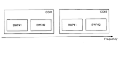
- FIG. 2 is a diagram for explaining BWP.
- CC # 1 includes a plurality of BWPs (# 1 and # 2)
- CC # 2 includes a plurality of BWPs (# 1 and # 2).
- the number after # indicates the index.
- CC Component Carrier
- Throughput can be expected to be improved by the terminal device 200 performing communication processing with a plurality of CCs at the same time.
- the CC includes a plurality of frequency bands called BWP (Band Width Part).
- BWP divides CC, which is one operation bandwidth, into a plurality of frequency bandwidths.
- different Subcarrier spacings can be set.
- This BWP has been standardized as the basic frame format for the NR of 3GPP Rel15.
- the subcarrier interval was fixed at 15 kHz.
- the subcarrier interval can be set to 60 kHz, 120 kHz or 240 kHz. The longer the subcarrier interval, the shorter the OFDM symbol length. For example, in LTE, since the subcarrier interval is 15 kHz, one slot can be transmitted per 1 ms, in other words, 14 OFDM symbols can be transmitted.
- 2 slots can be transmitted when the subcarrier interval is 60 kHz
- 4 slots can be transmitted when the subcarrier interval is 120 kHz
- 8 slots can be transmitted when the subcarrier interval is 240 kHz.
- BWP with different subcarrier intervals can be provided at the same time. Therefore, NR can simultaneously provide a plurality of BWPs corresponding to different use cases.
- 3GPP Rel15 and Rel16 specify a system in which the terminal device 200 cannot transmit and receive using a plurality of BWPs at the same time. Such a system can perform transmission / reception using a plurality of antenna panels described later.
- the terminal device 200 receives data transmitted from a plurality of base stations (TRPs) by each of the plurality of antenna panels, the terminal device 200 does not use the plurality of BWPs at the same time.
- TRPs base stations
- the base station 100 can improve the communication quality, for example, by performing beamforming and communicating with the terminal device 200.
- a beamforming method there are a method of generating a beam that follows the terminal device 200 and a method of selecting a beam that follows the terminal device 200 from the candidate beams. Since the former method requires a calculation cost each time a beam is generated, it is unlikely that it will be adopted in a future wireless communication system (for example, 5G). On the other hand, the latter method is also adopted in FD-MIMO (Full Dimension Multiple Input Multiple Output) of Release 13 of 3GPP (Third Generation Partnership Project). The latter method is also referred to as codebook based beam forming.
- FD-MIMO Full Dimension Multiple Input Multiple Output
- base station 100 prepares (that is, generates) beams in all directions in advance.
- the base station 100 selects a beam suitable for the target terminal device 200 from the beams prepared in advance, and communicates with the terminal device 200 using the selected beam.
- the base station 100 is capable of communicating at 360 degrees in the horizontal direction, for example, 360 types of beams are prepared in increments of 1 degree.
- the base station 100 prepares 720 types of beams.
- base station 100 prepares a beam for 180 degrees, for example, from ⁇ 90 degrees to +90 degrees.
- the terminal device 200 Since the terminal device 200 only observes the beam, it is not necessary to know the existence of the codebook on the base station 100 side.
- the plurality of beams prepared in advance by the base station 100 are also referred to as beam groups below.
- the beam group can be defined for each frequency band, for example. Also, the beam group can be defined for each Rx / Tx beam and for each downlink / uplink.
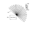
- Beam sweeping NR is a beam that transmits or receives a measurement signal (known signal) using each of a plurality of beams belonging to a beam group in order to select the optimum beam to be used for communication. Sweeping is being considered.
- the measurement signal may also be referred to as a reference signal.
- the optimum transmission beam (hereinafter, also referred to as Tx beam) can be selected based on the measurement result of the measurement signal transmitted while beam sweeping. An example thereof will be described with reference to FIG.
- the base station 100 transmits the measurement signal while beam sweeping (that is, switching the Tx beam) using the beam group 40.
- transmission while beam sweeping is also referred to as beam sweeping transmission below.
- the terminal device 200 measures the measurement signal transmitted by beam sweeping and determines which Tx beam is most easily received. In this way, the optimum Tx beam of the base station 100 is selected. By exchanging the base station 100 and the terminal device 200 and executing the same procedure, the base station 100 can select the optimum Tx beam of the terminal device 200.
- the terminal device 200 transmits a measurement signal by uplink. Then, the base station 100 receives the measurement signal while beam sweeping (that is, switching the Rx beam), and determines which Rx beam is most likely to be received. In this way, the optimum Rx beam of the base station 100 is selected. By exchanging the base station 100 and the terminal device 200 and executing the same procedure, the terminal device 200 can select the optimum Rx beam of the terminal device 200.
- receiving while beam-sweeping is also referred to as beam-sweeping reception below.
- the side that receives and measures the transmitted measurement signal reports the measurement result to the side that transmits the measurement signal.
- the measurement result includes information indicating which Tx beam is optimal.
- the optimum Tx beam is, for example, the Tx beam having the largest received power.
- the measurement result may include information indicating one Tx beam having the largest received power, or may include information indicating the top K Tx beams having the largest received power.
- the measurement result includes, for example, Tx beam identification information (for example, beam index) and information indicating the magnitude of the received power of the Tx beam (for example, RSRP (Reference Signal Received Power)) in association with each other.
- Tx beam identification information for example, beam index
- RSRP Reference Signal Received Power
- the measurement signal is beam-sweeping transmitted using each of the plurality of Tx beams belonging to the beam group. That is, for example, the base station 100 transmits a known signal, a reference signal, as a measurement signal with directivity. Therefore, it can be said that each of the Tx beams is identified by the measurement signal.
- a resource for transmitting a measurement signal transmitted using a beam may also be referred to as a beam resource.
- the transmission resource of the measurement signal transmitted by beam sweeping using the beam group may also be referred to as a beam resource group.
- the CSI acquisition procedure is executed after the optimum beam is selected by the beam selection procedure accompanied by the beam sweeping described above.
- the CSI acquisition procedure acquires the channel quality in communication using the selected beam. For example, in the CSI acquisition procedure, CQI (Channel Quality Indicator) is acquired.
- Channel quality is used to determine communication parameters such as modulation schemes. If a modulation method that can send only a few bits even though the channel quality is good, for example, QPSK (Quadrature Phase Shift Keying) is adopted, the throughput will be low. On the other hand, if a modulation method that can send many bits, for example, 256QAM (Quadrature Amplitude Modulation), is adopted even though the channel quality is poor, data reception fails on the receiving side and the throughput becomes low. .. In this way, it is important to acquire the channel quality correctly in order to improve the throughput.
- QPSK Quadrature Phase Shift Keying
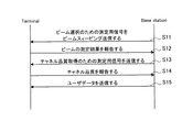
- FIG. 4 is a sequence diagram showing an example of the flow of a typical beam selection procedure and CSI acquisition procedure executed by the base station 100 and the terminal device 200.
- the base station 100 transmits a measurement signal for beam selection by beam sweeping (step S11).
- the terminal device 200 measures the measurement signal for beam selection, and reports the measurement result of the beam to the base station 100 (step S12).
- Such measurement results include, for example, information indicating the selection result of the optimum Tx beam of the base station 100.
- the base station 100 transmits a measurement signal for channel quality acquisition using the selected optimum beam (step S13).
- the terminal device 200 reports the channel quality acquired based on the measurement result of the measurement signal to the base station 100 (step S14).
- the base station 100 transmits the user data to the terminal device 200 using the communication parameters based on the reported channel quality (step S15).
- the channel quality of the downlink is measured based on the measurement signal transmitted on the downlink.
- downlink channel quality can also be measured based on the measurement signal transmitted on the uplink. This is because the uplink channels and the downlink channels have reversibility, and the quality of these channels is basically the same. Such reversibility is also referred to as channel receipt.
- the measurement result of the measurement signal for channel quality acquisition is reported. Reporting this measurement result can be a significant overhead.
- the channel can be represented by a matrix of N ⁇ M.
- FIG. 5 is a sequence diagram showing another example of the flow of a typical beam selection procedure and CSI acquisition procedure executed by the base station 100 and the terminal device 200.
- the terminal device 200 transmits the measurement signal for beam selection by beam sweeping, and the base station 100 receives the measurement signal while beam sweeping (step S21).
- the base station 100 selects the optimum Tx beam of the terminal device 200 and the optimum Rx beam of the base station 100 based on the measurement result.
- the base station 100 reports the measurement result of the beam to the terminal device 200 (step S22).
- the measurement result includes information indicating the selection result of the optimum Tx beam of the terminal device 200.
- the terminal device 200 transmits a measurement signal for channel quality acquisition using the selected Tx beam (step S23).
- the base station 100 acquires the uplink channel quality based on the measurement result, and acquires the downlink channel quality based on the uplink channel quality.
- the base station 100 transmits the user data to the terminal device 200 using the communication parameters based on the acquired downlink channel quality (step S24).
- FIG. 6 is a diagram for explaining antenna switching.
- the antenna set 50 shown in FIG. 6 has four antennas 51 (51A to 51D), four transmission / reception changeover switches 52 (52A to 52D), an antenna element changeover switch 53, and two transmission analog circuits 54 (54A and 54B). (An example of a transmission processing unit) and four receiving analog circuits 55 (55A to 55D) (an example of a receiving processing unit) are included.
- Each antenna 51 is also referred to as antenna # 0 to # 3.
- the antenna 51 radiates a signal as a radio wave into space, or converts a radio wave in space into a signal.
- the transmission / reception changeover switch 52 is a switch for switching between outputting a signal to be transmitted to the antenna 51 and outputting a signal received by the antenna 51 to the antenna element changeover switch 53.
- the antenna element changeover switch 53 is a switch for switching the connection between the transmission / reception changeover switch 52 and the transmission analog circuit 54 or the reception analog circuit 55.
- the transmission analog circuit 54 is a circuit that performs analog processing for transmitting a signal using the antenna 51.
- the reception analog circuit 55 is a circuit that performs analog processing for receiving a signal using the antenna 51.
- Each antenna 51 is switchably connected to the transmission analog circuit 54 or the reception analog circuit 55 via the transmission / reception changeover switch 52 and the antenna element changeover switch 53.
- the antenna element changeover switch 53 switches whether a signal is received or transmitted by each antenna 51.
- the number of receiving analog circuits 55 is four, which is the same as the number of antennas 51.
- the number of transmission analog circuits 54 is two, which is less than the number of antennas 51. Such a situation is caused, for example, by reducing the transmission analog circuit 54 in terms of cost.
- the antenna set 50 can receive a signal by using four antennas 51 at the same time.
- the antenna set 50 can transmit a signal by using two antennas 51 at the same time. In other words, the antenna set 50 cannot transmit signals using four antennas 51 at the same time. Therefore, the terminal device 200 having the antenna set 50 cannot transmit the measurement signal for channel quality acquisition by using the four antennas 51 at the same time. Since the number of antennas 51 that can be used simultaneously by the terminal device 200 differs between the downlink and the uplink, it is difficult for the base station 100 to acquire the channel quality of the downlink by using the channel recession. ..
- antenna switching As a countermeasure, there is a technology called antenna switching. An example thereof will be described with reference to FIGS. 7 to 9.
- the antenna element changeover switch 53 connects the transmission analog circuit 54A to the transmission / reception changeover switch 52A and the antenna 51A, and connects the transmission analog circuit 54B to the transmission / reception changeover switch 52B and the antenna 51B.
- the terminal device 200 having the antenna set 50 transmits a measurement signal for channel quality acquisition using the antennas 51A and 51B.
- the antenna element changeover switch 53 connects the transmission analog circuit 54A to the transmission / reception changeover switch 52C and the antenna 51C, and connects the transmission analog circuit 54B to the transmission / reception changeover switch 52D and the antenna 51D.
- the terminal device 200 having the antenna set 50 transmits a measurement signal for channel quality acquisition using the antennas 51C and 51D.
- Such switching of the connection between the antenna 51 and the transmission analog circuit 54 is also referred to as antenna switching.
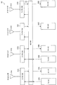
- FIG. 9 is a diagram showing an example of the relationship between antenna switching and the resource on which antenna switching is performed.
- the antenna set 50 in the state shown in FIG. 7 is the resource # 1 used for transmitting the measurement signal using the antennas # 0 and # 1
- the antenna set 50 in the state shown in FIG. 8 is the antenna # 2.
- resource # 2 used for transmitting the measurement signal using # 3 are shown.
- resource # 1 and resource # 2 are set to different time resources. Therefore, using these different time resources, measurement signals are transmitted using a total of four antennas 51, two in order. As a result, it is possible to transmit a measurement signal using a total of four antennas 51 as in the case of the downlink, so that channel recognition can be used.
- Resource # 2 is placed after resource # 1 after a predetermined time. In this way, a gap is provided between resource # 1 and resource # 2. This is because it takes time for the characteristics of the switched transmission analog circuit 54 to stabilize after the connection between the transmission analog circuit 54 and the antenna set 50 is switched. The above-mentioned gap is provided until the characteristics of the transmission analog circuit 54 whose connection with the antenna 51 is switched stabilizes.
- a gap is, for example, a length of about 1 OFDM symbol, but is not limited to this, and may be a length other than the 1OFDM symbol.
- a signal for antenna switching is transmitted.
- the signal for antenna switching is transmitted, for example, at a certain time resource of a certain BWP. That is, antenna switching is carried out at a certain time resource of a certain BWP.
- the signal for antenna switching is, for example, a measurement signal.
- An antenna panel is a device including one or more antennas, one or more transmission analog circuits for signal transmission using antennas, and one or more reception analog circuits for signal reception using antennas.
- the number of transmission analog circuits and reception analog circuits included in the antenna panel may be indicated as 2T4R.
- 2T4R indicates that the antenna panel contains two transmit analog circuits and four receive analog circuits.
- 1T8R indicates that the antenna panel contains one transmit analog circuit and eight receive analog circuits.
- the number before T indicates the number of transmission systems
- the number before R indicates the number of reception systems.
- the base station 100 gives an instruction to the terminal device 200 as to which antenna panel the terminal device 200 uses to perform antenna switching. I could't.
- the base station 100 transmits a notification including information regarding the reference signal to the terminal device 200.
- a reference signal is, for example, a measurement signal transmitted by the base station 100 for the terminal device 200 to observe the channel quality in step S13 of FIG.
- the terminal device 200 When the terminal device 200 receives the notification including the information regarding the reference signal, the terminal device 200 performs antenna switching on the antenna panel that has received the reference signal.
- the base station 100 can control the terminal device 200 to specify the antenna panel that has received the reference signal and perform antenna switching by transmitting a notification including information about the reference signal. Therefore, the resources used for transmitting the measurement signal can be allocated on the premise that the antenna switching using the antenna panel is performed, and the resources can be used more effectively. An example in which the base station 100 makes effective use of resources will be described later.
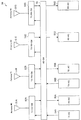
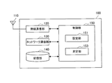
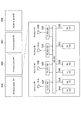
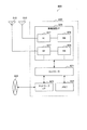
- FIG. 10 is a block diagram showing an example of the configuration of the base station 100 according to the present embodiment.
- the base station 100 includes an antenna unit 110, a wireless communication unit 120, a network communication unit 130, a storage unit 140, and a control unit 150.
- Antenna unit 110 The antenna unit 110 radiates the signal output by the wireless communication unit 120 into space as a radio wave. Further, the antenna unit 110 converts a radio wave in space into a signal and outputs the signal to the wireless communication unit 120.
- the antenna unit 110 of the present embodiment has a plurality of antenna elements and can form a beam.
- the wireless communication unit 120 transmits and receives signals.
- the wireless communication unit 120 transmits a downlink signal to the terminal device 200 and receives an uplink signal from the terminal device 200.
- the wireless communication unit 120 of the present embodiment can form a plurality of beams by the antenna unit 110 and communicate with the terminal device 200.
- the network communication unit 130 transmits / receives information.
- the network communication unit 130 transmits information to another node and receives information from the other node.
- the other node includes another base station 100 and a core network node.
- Storage unit 140 The storage unit 140 temporarily or permanently stores the program and various data for the operation of the base station 100.
- Control unit 150 controls the operation of the entire base station 100 to provide various functions of the base station 100.
- the control unit 150 includes a setting unit 151 and a measuring unit 153.
- the setting unit 151 has a function of making settings related to communication with the terminal device 200. For example, the setting unit 151 sets the antenna panel for performing antenna switching and sets the resources for performing antenna switching. Then, the setting unit 151 notifies the terminal device 200 of an instruction regarding antenna switching, such as a notification including information regarding a reference signal.
- the measurement unit 153 has a function of measuring the uplink measurement signal transmitted from the terminal device 200 and performing various processes based on the measurement result. For example, the measuring unit 153 measures the measurement signal transmitted by beam sweeping from the terminal device 200 as described above with reference to FIG. 5, and measures the optimum Tx beam of the terminal device 200 and the base station 100. Select the optimal Rx beam for. Further, the measuring unit 153 measures the measurement signal transmitted from the terminal device 200 using the optimum Tx beam as described above with reference to FIG. 5, and acquires the uplink channel quality. Then, the measuring unit 153 acquires the downlink channel quality based on the acquired uplink channel quality.
- the control unit 150 may further include other components other than these components. That is, the control unit 150 can perform operations other than the operations of these components.
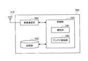
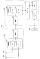
- FIG. 11 is a block diagram showing an example of the configuration of the terminal device 200 according to the present embodiment.
- the terminal device 200 includes an antenna unit 210, a wireless communication unit 220, a storage unit 230, and a control unit 240.
- Antenna unit 210 The antenna unit 210 radiates the signal output by the wireless communication unit 220 into space as a radio wave. Further, the antenna unit 210 converts a radio wave in space into a signal and outputs the signal to the wireless communication unit 220.
- the antenna unit 210 of the present embodiment has a plurality of antenna elements and can form a beam.
- the wireless communication unit 220 transmits and receives signals.
- the wireless communication unit 220 receives the downlink signal from the base station 100 and transmits the uplink signal to the base station 100.
- the wireless communication unit 220 of the present embodiment can form a plurality of beams by the antenna unit 210 and communicate with the base station 100.
- the antenna unit 210 and the wireless communication unit 220 are configured to include a plurality of antenna panels 60, which will be described later with reference to FIG.
- the antenna unit 210 corresponds to the antenna 51 shown in FIG.
- the wireless communication unit 220 is used in the transmission / reception changeover switch 52, the antenna element changeover switch 53, the transmission analog circuit 54 (an example of the transmission processing unit), and the reception analog circuit 55 (an example of the reception processing unit) shown in FIG. Equivalent to.
- Storage unit 230 The storage unit 230 temporarily or permanently stores the program and various data for the operation of the terminal device 200.
- Control unit 240 controls the operation of the entire terminal device 200 to provide various functions of the terminal device 200.
- the control unit 240 includes a reporting unit 241 and an antenna control unit 243.
- the reporting unit 241 has a function of reporting various information used for control by the base station 100 regarding antenna switching to the base station 100. For example, the reporting unit 241 reports the antenna panel configuration information and the capability information described later to the base station 100.
- the antenna control unit 243 has a function of controlling the implementation of antenna switching based on the control from the base station 100. For example, the antenna control unit 243 performs antenna switching by the antenna panel 60 instructed by the base station 100 among the plurality of antenna panels 60 in the resource instructed by the base station 100.
- the control unit 240 may further include other components other than these components. That is, the control unit 240 may perform operations other than the operations of these components.
- FIG. 12 is a diagram showing an example of the configuration of a plurality of antenna panels 60 included in the terminal device 200 according to the present embodiment.
- the terminal device 200 includes a plurality of antenna panels 60 (60A to 60D). Each antenna panel 60 is also referred to as antenna panels # 0 to # 3.
- the antenna panel 60A includes the same configuration as the antenna set 50 described above with reference to FIG.
- the antenna panels 60B to 60D may include an antenna set 50 having the same or different configuration as the antenna panel 60A.
- the configuration of the antenna set 50 is the same as that of the antenna set 50 shown in FIG. 6, so the description thereof will be omitted.
- the terminal device 200 may include four antenna panels 60 having four antennas 51.
- the plurality of antenna panels 60 described above are used, for example, when receiving a plurality of data from a base station 100 called a TRP (Transmission Reception Point). More specifically, the terminal device 200 receives the downlink data from each TPR at each antenna panel 60.
- TRP Transmission Reception Point
- one antenna panel 60 basically forms one beam.
- analog beamforming is performed in which a beam is formed by adjusting the phase of a signal with a phase shifter (phase shifter) of the transmission analog circuit 54 or the reception analog circuit 55.
- the terminal device 200 directs the Rx beam in different directions on the plurality of antenna panels 60 and receives the data.
- Data transmitted by a plurality of TRPs may be received in bands of different frequencies, but in the present embodiment, unless otherwise specified, the data is basically operated in the same frequency band and in the same BWP. It shall be done.
- the throughput can be improved by receiving the data transmitted by the plurality of TRPs on the plurality of antenna panels 60.
- the terminal device 200 may or may not be able to use the plurality of antenna panels 60 for reception at the same time.
- the terminal device 200 uses the plurality of antenna panels 60 in different frequency bands to receive data at the same time.
- the terminal device 200 may use the beams formed in different directions in each of the plurality of antenna panels 60 so that the plurality of antenna panels 60 receive data at the same time.
- the terminal device 200 uses the plurality of antenna panels 60 by switching them in a time division manner.
- the terminal device 200 may or may not be able to use a plurality of antenna panels 60 for transmission at the same time.
- the terminal device 200 transmits data at the same time using the plurality of antenna panels 60 in different frequency bands.
- the terminal device 200 may transmit data to the plurality of antenna panels 60 at the same time by using beams formed in different directions in the plurality of antenna panels 60, respectively.
- the terminal device 200 switches the plurality of antenna panels 60 in a time division manner for transmission.
- the simultaneous transmission has a large burden on the terminal device 200 from the viewpoint of power consumption, for example, and is difficult to realize.
- the terminal device 200 performs antenna switching and transmits a reference signal (for example, a measurement signal) when a plurality of antenna panels 60 cannot transmit and receive at the same time
- a reference signal for example, a measurement signal
- the present invention is not limited thereto. ..
- the technique according to this embodiment can also be applied when the terminal device 200 can use a plurality of antenna panels 60 at the same time.
- TRP ⁇ 2.4.
- a plurality of TRPs are base stations 100 arranged in a predetermined area. Therefore, a plurality of TRPs exist around the terminal device 200.
- the terminal device 200 receives the data transmitted from the plurality of TRPs at the same time or at different times. For example, when the terminal device 200 receives data from a plurality of TRPs at the same time, the throughput can be improved according to the number of TRPs as compared with the case where the terminal device 200 receives a plurality of data from one TRP. For example, when data is received from n TRPs at the same time, the throughput of the terminal device 200 is expected to increase n times.
- the terminal device 200 uses a different antenna panel 60 for each TRP to transmit / receive data.
- the terminal device 200 When the data transmitted by different TRPs is received by the same antenna panel 60, the terminal device 200 cannot receive the data at the same time and receives the data in time division. This is because one antenna panel 60 does not form a plurality of beams at the same time, but one beam is formed. Therefore, for example, when data is transmitted from each of TRP # 1 and TRP # 2, the terminal device 200 first receives the data transmitted by TRP # 1, and then receives the data transmitted by TRP # 2.
- the base station 100 When the terminal device 200 receives data from a plurality of TRPs, the base station 100 needs to acquire the downlink channel quality for each of the plurality of TRPs. As described above, when the base station 100 acquires the downlink channel quality, the base station 100 estimates the downlink channel quality by observing the uplink channel using the channel recession. Therefore, when communicating using different antenna panels 60 for each of the plurality of TRPs, the base station 100 causes the terminal device 200 to transmit measurement signals while performing antenna switching on each antenna panel 60, thereby causing a plurality of TRPs. It is necessary to observe the uplink channel.
- the terminal device 200 uses the resources specified by the base station 100 to measure each antenna.
- Uplink channel measurement signals are transmitted from the panel 60, respectively.
- the channel measurement signal for example, SRS (Sounding Reference Signal), which is an uplink reference signal, is used.
- the base station 100 multiplexes the SRS resources used for antenna switching in the plurality of antenna panels 60 in a time division manner. More specifically, the base station 100 multiplies the SRS resources used for antenna switching in a plurality of antenna panels 60 by time division by utilizing the gap required when switching the antenna 50 in one antenna panel 60. do.
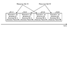
- FIG. 13 is a diagram showing an arrangement example of SRS resources used for antenna switching in a plurality of antenna panels 60.
- FIG. 13 shows the resource allocation when the 1T2R antenna panel # 1 and the 1T2R antenna panel # 2 transmit SRS.
- the antenna panel # 1 transmits SRS to, for example, TRP # 1
- the antenna panel # 2 transmits SRS to, for example, TRP # 2.
- the set of SRS resources for the antenna panel # 1 to perform antenna switching and transmit the SRS is described as a resource set (Resource Set) # 1.
- the set of SRS resources for the antenna panel # 2 to perform antenna switching and transmit the SRS is described as a resource set (Resource Set) # 2.
- a gap is provided between the resource R11 for SRS transmission using the antenna # 1 of the antenna panel # 1 and the resource R12 for SRS transmission using the antenna # 2. Be done. In this way, after the resource set # 1 having a gap between the two resources, the resource set # 2 having a gap in the same manner is arranged. In the resource set # 2, the resource R21 for SRS transmission using the antenna # 1 and the resource R22 for SRS transmission using the antenna # 2 are arranged with a gap.
- the SRS resources particularly the resources in the time domain, increase by the amount of the gaps provided. This is because as the number of times the antenna 50 is switched increases or the number of antenna panels 60 increases, the number of gaps also increases, and the proportion of SRS resources (time resources) in the time domain also increases. be.
- a gap is also provided between the resource set # 1 and the resource set # 2, but since the switching response time between the plurality of antenna panels 60 is fast, such a gap is provided for a short time or a gap. It does not have to be. This is because when switching the antenna panel 60, it is not necessary to switch the connection between the transmission analog circuit 54 and the antenna 50.
- the SRS resource used by the base station 100 for antenna switching on the plurality of antenna panels 60 is time-divisioned by utilizing the gap required when switching the antenna 50 on one antenna panel 60. Multiplex.
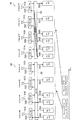
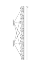
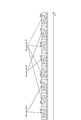
- FIG. 14 is a diagram showing an arrangement example of SRS resources used for antenna switching in the plurality of antenna panels 60 according to the embodiment of the present disclosure.
- the base station 100 uses the resource R21 (time resource) used when performing antenna switching of the antenna panel # 2 (corresponding to the first antenna panel) to the antenna panel # 1 (second antenna panel). It is arranged between a plurality of resources R11 and R12 that perform antenna switching (corresponding to). The base station 100 arranges the resource R22 after the resource R12.
- the base station 100 does not need to provide a gap between the resource R11 and the resource R21. Similarly, the base station 100 does not need to provide a gap between the resource R21 and the resource R12 and between the resource R12 and the resource R22.
- the base station 100 can reduce the time resources required for antenna switching, and can improve the resource utilization efficiency.
- FIG. 15 is a diagram showing an arrangement example of SRS resources used for antenna switching in a plurality of antenna panels 60.
- FIG. 15 shows the resource allocation when the 1T4R antenna panel # 1 and the 1T4R antenna panel # 2 transmit SRS.
- the antenna panel # 1 transmits SRS to, for example, TRP # 1
- the antenna panel # 2 transmits SRS to, for example, TRP # 2.
- the set of SRS resources for the antenna panel # 1 to perform antenna switching and transmit the SRS is described as a resource set (Resource Set) # 1.
- the set of SRS resources for the antenna panel # 2 to perform antenna switching and transmit the SRS is described as a resource set (Resource Set) # 2.
- resources R11 to R14 are arranged in the resource set # 1 with a gap for SRS transmission using the antennas # 1 to # 4 of the antenna panel # 1, respectively. Further, the resource set # 2 is arranged after the resource set # 1. Resources R21 to R24 are arranged in the resource set # 2 with gaps for SRS transmission using the antennas # 1 to # 4 of the antenna panel # 2.
- the base station 100 multiplexes the SRS resources used for antenna switching in the plurality of antenna panels 60 in a time division manner.
- FIG. 16 is a diagram showing an arrangement example of SRS resources used for antenna switching in the plurality of antenna panels 60 according to the embodiment of the present disclosure.
- the base station 100 alternately arranges the resources R11 to R14 of the resource set # 1 and the resources R21 to R24 of the resource set # 2.
- the base station 100 can reduce the time resources required for antenna switching, and the resources can be reduced. Utilization efficiency can be improved.
- FIG. 17 is a diagram showing an arrangement example of SRS resources used for antenna switching in a plurality of antenna panels 60.
- FIG. 17 shows the resource allocation when the 2T4R antenna panel # 1 and the 2T4R antenna panel # 2 transmit SRS.
- the antenna panel # 1 transmits SRS to, for example, TRP # 1
- the antenna panel # 2 transmits SRS to, for example, TRP # 2.
- the set of SRS resources for the antenna panel # 1 to perform antenna switching and transmit the SRS is described as a resource set (Resource Set) # 1.
- the set of SRS resources for the antenna panel # 2 to perform antenna switching and transmit the SRS is described as a resource set (Resource Set) # 2.
- the resource set # 1 includes the resource R112 for SRS transmission using the antennas # 1 and # 2 of the antenna panel # 1 and the resource R112 for SRS transmission using the antennas # 3 and # 4.
- the resource R134 and the resource R134 of the above are arranged with a gap.
- the resource set # 2 is arranged after the resource set # 1. In the resource set # 2, there is a gap between the resource R212 for SRS transmission using the antennas # 1 and # 2 of the antenna panel # 2 and the resource R234 for SRS transmission using the antennas # 3 and # 4. It is provided and arranged.
- the SRS resource used by the base station 100 for antenna switching in the plurality of antenna panels 60 is time-division-multiplexed in the same manner as in 1T2R.
- FIG. 18 is a diagram showing an arrangement example of SRS resources used for antenna switching in the plurality of antenna panels 60 according to the embodiment of the present disclosure.
- the base station 100 alternately arranges the resources R112 and R134 of the resource set # 1 and the resources R212 and R234 of the resource set # 2.
- the base station 100 can reduce the time resources required for antenna switching, and the resources of the resources can be reduced. Utilization efficiency can be improved.
- FIG. 19 is a diagram showing an arrangement example of SRS resources used for antenna switching in the plurality of antenna panels 60 according to the embodiment of the present disclosure.
- FIG. 19 shows the resource allocation when the 1T2R antenna panel # 1, the 1T4R antenna panel # 2, and the 1T2R antenna panel # 3 transmit SRS.
- the antenna panel # 1 transmits SRS to, for example, TRP # 1
- the antenna panel # 2 transmits SRS to, for example, TRP # 2.
- Antenna panel # 3 transmits SRS to, for example, TRP # 3.
- the set of SRS resources for the antenna panel # 1 to perform antenna switching and transmit the SRS is described as a resource set (Resource Set) # 1.
- the resource set # 1 includes a resource R11 for the SRS transmitted by the antenna # 1 and a resource R12 for the SRS transmitted by the antenna # 2.
- Resource Set # 1 includes resources R21 to R24 for SRS transmitted by antennas # 1 to # 4.
- Resource set # 3 includes resource R31 for SRS transmitted by antenna # 1 and resource R32 for SRS transmitted by antenna # 2.
- the base station 100 alternately arranges the resources R22 to R24 included in the resource set # 2 and the resources R11, R12, R31, and R32 included in the resource sets # 1 and # 3.
- the resources included in one resource set are not continuously arranged, and the base station 100 does not need to provide a gap between the resources.
- the base station 100 can reduce the time resource required for antenna switching, and can improve the resource utilization efficiency.
- the number of transmission and reception systems and the number of antenna panels 60 described above are examples, and are not limited thereto.
- the base station 100 may arrange each resource so that the resources included in one resource set are not continuous, and the number of systems and the number of antenna panels can take various values.
- the resource allocation by the base station 100 may become complicated. Therefore, for example, in the base station 100 of the present embodiment, when antenna switching is performed on a plurality of antenna panels 60 having the same number of systems, the resource set is time-division-multiplexed. Specifically, for example, when the base station 100 switches a plurality of 1T2R antenna panels 60 to perform antenna switching, the base station 100 performs time division multiplexing of the resource set using the Gap described above.
- the complexity of resource allocation of the base station 100 can be reduced, and the complexity of switching between the antenna panel 60 and the antenna 50 in the terminal device 200 can be reduced.
- 3GPP Rel15 and Rel16 stipulate that the terminal device 200 cannot transmit signals using a plurality of antenna panels 60 at the same time.
- the terminal device 200 simultaneously uses a plurality of antenna panels 60 for transmission.
- the terminal device 200 simultaneously uses the plurality of antenna panels 60 for transmission in this way, it is desirable to reduce the time resource for antenna switching.
- the base station 100 allocates SRS resources allocated for antenna switching of each antenna panel 60 in the frequency domain. Multiplex.
- FIG. 20 is a diagram showing an arrangement example of SRS resources used for antenna switching in the plurality of antenna panels 60 according to the embodiment of the present disclosure.
- FIG. 20 shows the resource allocation when the 2T4R antenna panel # 1 and the 2T4R antenna panel # 2 transmit SRS.
- the antenna panel # 1 transmits SRS to, for example, TRP # 1
- the antenna panel # 2 transmits SRS to, for example, TRP # 2.
- the set of SRS resources for the antenna panel # 1 to perform antenna switching and transmit the SRS is described as a resource set (Resource Set) # 1.
- the set of SRS resources for the antenna panel # 2 to perform antenna switching and transmit the SRS is described as a resource set (Resource Set) # 2.
- the resource set # 1 includes the resource R112 for SRS transmission using the antennas # 1 and # 2 of the antenna panel # 1 and the resource R112 for SRS transmission using the antennas # 3 and # 4.
- the resource R134 and the resource R134 of the above are arranged with a gap.
- the resource set # 2 is arranged in a frequency domain different from that of the resource set # 1. In the resource set # 2, there is a gap between the resource R212 for SRS transmission using the antennas # 1 and # 2 of the antenna panel # 2 and the resource R234 for SRS transmission using the antennas # 3 and # 4. It is provided and arranged.
- the base station 100 multiplexes the SRS resources allocated for the antenna switching of each antenna panel 60 in the frequency domain. Time resources can be reduced.
- the base station 100 allocates resources for each of a plurality of antenna panels 60, but there is a method in which the base station 100 specifically specifies which antenna panel 60 the terminal device 200 transmits SRS. There was no such thing in the past. That is, conventionally, the base station 100 specifies the SRS resource to be used for antenna switching, but cannot specifically specify which antenna panel 60 to use, and which antenna panel 60 should be used to send the SRS. , The terminal device 200 was unknown.
- the base station 100 designates the antenna panel 60 that performs antenna switching using the designated SRS resource by using the downlink reference signal.
- the downlink reference signal is, for example, CSI-RS (Channel State Information Reference Signal).
- Base station 100 transmits a plurality of CSI-RSs as downlink reference signals.
- the base station 100 transmits a notification including information about one CSI-RS out of a plurality of CSI-RSs to the terminal device 200, and the antenna panel 60 used when receiving the CSI-RS included in the notifications. Is specified and the terminal device 200 is requested to transmit the SRS.
- the base station 100 designates the antenna panel 60 having the CSI-RS and Spatial Relation.
- Spatial Relation is for the base station 100 to request the terminal device 200 to perform transmission using the same antenna panel 60 as the antenna panel 60 used when receiving the CSI-RS.
- the terminal device 200 selects and receives the desired antenna panel 60 by itself.
- the desirable antenna panel 60 is, for example, an antenna panel 60 that can form a beam having a large received power.
- the base station 100 designates the terminal device 200 to transmit the SRS, which is an uplink reference signal, by using the antenna panel 60 used when the CSI-RS is received.
- the base station 100 shall transmit CSI-RS # 1 and CSI-RS # 2 to the terminal device 200 as downlink reference signals.
- the base station 100 notifies the terminal device 200 of information about CSI-RS # 1, for example, as an antenna panel 60 for transmitting SRS in the resource set # 1, and an antenna that receives CSI-RS # 1.
- the base station 100 receives CSI-RS # 2 as an antenna panel 60 for transmitting SRS in the resource set # 2 by notifying the terminal device 200 of information about CSI-RS # 2, for example. Specify 60.
- the base station 100 can specify the antenna panel 60 using the SRS resources multiplexed in the time direction described above by transmitting the notification including the information regarding the reference signal to the terminal device 200. As a result, the base station 100 can allocate resources to the predetermined antenna panel 60, and the resource utilization efficiency can be further improved.
- the antenna panel 60 used by the terminal device 200 for receiving CSI-RS # 1 and CSI-RS # 2 is the same, in other words, one antenna panel is used for CSI-RS # 1 and CSI-RS.
- both # 2 are received.
- the terminal device 200 even if the base station 100 specifies CSI-RS # 1 and CSI-RS # 2, the terminal device 200 both transmits the SRS using the same antenna panel 60. Therefore, the base station 100 cannot multiplex the SRS resource in the time direction by utilizing the gap of the resource set described above.
- the base station 100 acquires information (hereinafter, may also be referred to as a stamp) regarding the antenna panel 60 used when the base station 100 receives the CSI-RS from the terminal device 200.
- the base station 100 can confirm whether or not the antenna panels 60 that have received the plurality of CSI-RSs are the same, and can appropriately specify the antenna panels 60 to be used in the SRS resource. become.
- the terminal device 200 When the received power of CSI-RS # 1 is the largest among the plurality of CSI-RS received while beam sweeping, the terminal device 200 reports to the base station 100 to that effect. At this time, the terminal device 200 reports such a report including information indicating which antenna panel 60 received CSI-RS # 1. Similarly, the terminal device 200 received the CSI-RS # 2 on which antenna panel 60 when the received power of the CSI-RS # 2 was the largest among the plurality of CSI-RS received while beam-sweeping. It is reported to the base station 100 including the information indicating the above.
- FIG. 21 is a chart for explaining an example of information reported by the terminal device 200 according to the embodiment of the present disclosure.
- the terminal device 200 reports the information that the CRI (CSI-RS resource Identity) is CSI-RS # 1 as the information for identifying the desired CSI-RS as the report for the CSI-RS # 1. do. Further, the terminal device 200 reports the antenna panel 60 that has received CSI-RS # 1 including information for identifying the antenna (identification information: ID). In the example of FIG. 21, the terminal device 200 reports including the Antenna Panel ID indicating that the antenna panel # 1 is used.
- CRI CSI-RS resource Identity
- the terminal device 200 reports information that CRI (CSI-RS resource Identity) is CSI-RS # 2 as information for identifying a desirable CSI-RS. Further, the terminal device 200 reports the antenna panel 60 that has received CSI-RS # 2 including information for identifying the antenna (identification information: ID). In the example of FIG. 21, the terminal device 200 reports including the Antenna Panel ID indicating that the antenna panel # 2 is used.
- CRI CSI-RS resource Identity
- FIG. 22 is a chart for explaining another example of the information reported by the terminal device 200 according to the embodiment of the present disclosure.
- the terminal device 200 reports information that CRI (CSI-RS resource Identity) is CSI-RS # 1 as information for identifying a desirable CSI-RS. do. Further, the terminal device 200 reports the antenna panel 60 that has received CSI-RS # 1 including information for identifying the antenna (identification information: ID). In the example of FIG. 22, the terminal device 200 reports including the Antenna Panel ID indicating that the antenna panel # 1 is used.
- CRI CSI-RS resource Identity
- the terminal device 200 reports information that CRI (CSI-RS resource Identity) is CSI-RS # 2 as information for identifying a desirable CSI-RS. Further, the terminal device 200 reports the antenna panel 60 that has received CSI-RS # 2 including information for identifying the antenna (identification information: ID). In the example of FIG. 22, the terminal device 200 reports including the Antenna Panel ID indicating that the antenna panel # 1 is used.
- CRI CSI-RS resource Identity
- the terminal device 200 notifies the base station 100 of information regarding the antenna panel 60 used for receiving the CSI-RS. Thereby, the base station 100 can confirm whether or not the terminal device 200 uses the same antenna panel 60 for receiving the plurality of CSI-RSs.
- the base station 200 arranges a plurality of resource sets side by side in the time direction, for example, as shown in FIGS. 13, 15, and 17. , Notify the terminal device 200 of such arrangement.
- the base station 200 alternately alternates the resources included in the plurality of resource sets, as shown in FIGS. 14, 16 and 18, for example. By arranging them in the same direction, the terminals are multiplexed in the time direction, and the terminal device 200 is notified of such arrangement.
- FIG. 23 is a diagram for explaining the conventional Spatial Relation Info.
- the Spatial Relation Info shown in FIG. 23 is described in 3GPP TS36.311.
- the base station 100 uses Spatial Relation Info to specify a beam to be used when transmitting an SRS resource. More specifically, the base station 100 uses Spatial Relation Info to specify that a Tx beam pointing in the same direction as the Rx beam used for receiving CSI-RS and SSB (Synchronization Signal Block) is used. ..
- FIG. 24 is a diagram for explaining the SRS resource set according to the embodiment of the present disclosure.
- Spatial Relation Info that specifies the SRS resource set used for antenna switching is provided. Therefore, in this embodiment, a new SRS resource set is defined.
- the ID of the SRS resource set and the SRS resource belonging to the resource set identified by the ID are comprehensively associated with each other. That is, for example, in the case of the resource allocation shown in FIG. 14, depending on the newly defined SRS resource set, the resource sets # 1 and # 2 and the resources R11, R12, and R21 included in the resource sets # 1 and # 2, respectively, R22 is associated with each other. It is also specified that such an SRS resource set will be used for antenna switching.
- Spatial Relation Info is provided in the SRS resource set of the present embodiment.
- the base station 100 may specify two or more CSI-RSs. That is, the base station 100 may specify a plurality of CSI-RSs reported by the terminal device 200 as having been received from the plurality of TRPs. By designating a plurality of CSI-RSs, the base station 100 designates the terminal device 200 to transmit the antenna switching SRS using the antenna panel 60 that has received the designated CSI-RSs.
- the SRS resource set shown in FIG. 24 sets one resource set (for example, resource set # 1), and is different for setting another resource set (for example, resource set # 2).
- SRS resource set is used. That is, for example, when antenna switching is performed by two antenna panels 60, two SRS resource sets shown in FIG. 24 are set.
- a plurality of resource sets are set by the base station 100 transmitting the information "csi-RS-Index1, csi-RS-Index2" to the terminal device 200 by one information element in the DCI (Downlink Control Information). You may specify # 1 and # 2. In this case, the base station 100 can also specify which CSI-RS is used when the antenna panel 60 is used for antenna switching.
- the base station 100 can specify the antenna panel 60 used for antenna switching.
- the base station 100 can arrange the SRS resources in consideration of the antenna panel 60 used for antenna switching, and the resources can be used more effectively.
- the base station 100 By designating the antenna panel 60 used for antenna switching, the base station 100 according to the present embodiment can multiplex the resource set as described above and shorten the transmission time of SRS of all the antenna panels 60. can. As a result, the base station 100 can further improve the measurement accuracy of the channel quality and can improve the throughput.
- the base station 100 is an antenna switching including information (for example, 1T2R or 1T4R) regarding the number of transmission analog circuits 54 (example of transmission processing unit) and the number of reception analog circuits 55 (example of reception processing unit) allocated by SRS resources, for example.
- a notification specifying the mode is transmitted to the terminal device 200.
- 1T of 1T2R indicates that the number of transmission analog circuits 54, in other words, the number of antennas used for transmission is one.
- 2R of 1T2R indicates that the number of receiving analog circuits 55, in other words, the number of antennas used for reception is two.
- the terminal device 200 performs antenna switching on the antenna panel 60 based on the notification.
- the antenna switching on the antenna panel 60 of 1T2R, 1T4R and 1T8R is defined.
- antenna switching is also possible with the antenna panel 60 other than these antenna panels 60.
- antenna switching on the 1T6R antenna panel 60 can also be defined, but defining antenna panels 60 other than 1T2R, 1T4R and 1T8R complicates the system.
- the definition of 1T12R is also required.
- the number of the transmission analog circuit 54 and the reception analog circuit 55 of the antenna panel 60 capable of performing the antenna switching increases, it may become difficult to support the antenna switching in the antenna panel 60.
- antenna switching in the antenna panels 60 of 1T2R, 1T4R and 1T8R is defined, in other words, the base station 100 allocates SRS resources to the antenna panels 60 of 1T2R, 1T4R and 1T8R. .. In this way, the base station 100 allocates SRS resources assuming that the antenna panel 60 has a power of 2 for the number of transmission analog circuits 54 and a power of 2 for the reception analog circuits 55.
- the terminal device 200 uses the allocated SRS resource for antenna switching.
- the antenna panel 60 of the transmission analog circuit 54 and the reception analog circuit 55 which is equal to or less than the number of transmission analog circuits 54 and the number of reception analog circuits 55 to which the base station 100 has allocated SRS resources. Perform antenna switching at.
- the terminal device 200 when the SRS resource of 1T8R is allocated from the base station 100, the terminal device 200 performs antenna switching on the antenna panel 60 of 1T6R, which has fewer reception analog circuits 55 than 1T8R.
- the terminal device 200 Even when the SRS resource of 1T8R is allocated from the base station 100, if the terminal device 200 has only the antenna panel 60 of 1T2R or less, it is determined that the setting error of the base station 100 is made and the antenna is used. Switching may not be performed.
- the terminal device 200 includes an antenna panel 60 (for example, a 1T6R antenna panel 60) including a transmission analog circuit 54 or a reception analog circuit 55 which is not a power of 2.
- the terminal device 200 performs antenna switching on the antenna panel 60 of the 1T6R when, for example, the SRS resource of the 1T8R is allocated from the base station 100.
- the terminal device 200 determines that it is a setting error of the base station 100 and does not perform antenna switching.
- the antenna switching may be performed by the allocated SRS resource. More specifically, the terminal device 200 receives the antenna panel when the SRS resource is allocated by the power of 2 closest to the number of the transmitting analog circuit 54 and the receiving analog circuit 55 of the antenna panel 60 owned by the terminal device 200. Antenna switching is performed at 60.
- antenna switching can be performed without increasing the time and effort of resource allocation by the base station 100. Can be done.
- the base station 100 notifies the terminal device 200 of information indicating whether or not the antenna panel 60 may perform antenna switching with the allocated SRS resource other than the capacity assumed at the time of allocation. May be good.
- the terminal device 200 may perform antenna switching on an antenna panel 60 other than 1T8R (for example, 1T6R or 1T2R).
- the terminal device 200 performs antenna switching on the antenna panel 60 of 1T8R, and does not perform antenna switching on the other antenna panels 60.
- the base station 100 can explicitly notify whether or not antenna switching can be performed.
- Terminal device capabilities In order to carry out the antenna switching described above, the terminal device 200 notifies the base station 100 of its capabilities. As a result, the base station 100 can set an appropriate SRS resource according to the capability of the terminal device 200.
- FIG. 25 is a diagram for explaining the capability transmitted from the terminal device 200 to the base station 100 according to the embodiment of the present disclosure.
- the terminal device 200 notifies the base station 100 whether or not antenna switching corresponding to a plurality of TRPs is possible, for example.
- the terminal device 200 notifies the base station 100 of information (an example of mode information) regarding the antenna switching mode including information regarding the number of transmission analog circuits 54 and the number of reception analog circuits 55 (for example, 1T2R and 1T4R).
- the terminal device 200 notifies the base station 100 of mode information regarding the antenna switching mode that can be implemented by the terminal device 200.
- the terminal device 200 includes the antenna panels 60 of 1T2R and 1T4R, the terminal device 200 notifies the base station 100 of the mode information including "1T2R, 1T4R".
- the terminal device 200 notifies the base station 100 of information (an example of implementation information) indicating whether or not antenna switching can be performed in a mode other than the switching mode notified by the mode information. For example, even when the terminal device 200 is designated as 1T8R and the SRS resource is allocated, the terminal device 200 notifies the base station 100 of information indicating whether or not antenna switching is possible on the antenna panel 60 of, for example, 1T6R.
- information an example of implementation information
- the base station 100 may be notified of information indicating whether or not the above-mentioned Flag (for example, 1T8R Flag) can be determined by the base station 100.
- the above-mentioned Flag for example, 1T8R Flag
- the terminal device 200 notifies the base station 100 of its own capability required for antenna switching, so that the base station 100 can grasp the capability of the terminal device 200.
- the base station 100 can appropriately allocate SRS resources for antenna switching.
- the capability of the terminal device 200 described above is an example, and the terminal device 200 may notify the base station 100 of information other than the capability described above.
- FIG. 26 is a sequence diagram for explaining the flow of communication processing according to the embodiment of the present disclosure. The same processes as those shown in FIG. 5 are designated by the same reference numerals, and the description thereof will be omitted.
- the terminal device 200 first transmits information regarding the capability for performing antenna switching to the base station 100 (step S31).
- the base station 100 notifies the terminal device 200 of the resource allocation for antenna switching (step S32).
- the base station 100 designates the antenna panel 60 used by the terminal device 200 by notifying the information including the information regarding the downlink reference signal (for example, CSI-RS).
- the downlink reference signal for example, CSI-RS
- the terminal device 200 that received the report of the beam measurement result in step S22 performs antenna switching and transmits a measurement signal (for example, SRS) to the base station 100 (step S33). At this time, the terminal device 200 uses the designated antenna panel 60 based on the notification received in step S32, and transmits the measurement signal with the designated resource.
- a measurement signal for example, SRS
- the base station 100 may be realized as any kind of eNB (evolved Node B) such as a macro eNB or a small eNB.
- the small eNB may be an eNB that covers cells smaller than the macro cell, such as a pico eNB, a micro eNB, or a home (femto) eNB.
- the base station 100 may be realized as another type of base station such as NodeB or BTS (Base Transceiver Station).
- the base station 100 may include a main body (also referred to as a base station device) that controls wireless communication, and one or more RRHs (Remote Radio Heads) that are arranged at a location different from the main body.
- RRHs Remote Radio Heads
- various types of terminals which will be described later, may operate as the base station 100 by temporarily or semi-permanently executing the base station function.
- the terminal device 200 is a smartphone, a tablet PC (Personal Computer), a notebook PC, a portable game terminal, a mobile terminal such as a portable / dongle type mobile router or a digital camera, or an in-vehicle terminal such as a car navigation device. It may be realized as. Further, the terminal device 200 may be realized as a terminal (also referred to as an MTC (Machine Type Communication) terminal) that performs M2M (Machine To Machine) communication. Further, the terminal device 200 may be a wireless communication module (for example, an integrated circuit module composed of one die) mounted on these terminals.
- MTC Machine Type Communication
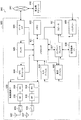
- FIG. 27 is a block diagram showing a first example of a schematic configuration of an eNB to which the techniques according to the present disclosure can be applied.
- the eNB 800 has one or more antennas 810 and a base station device 820. Each antenna 810 and base station device 820 may be connected to each other via an RF cable.
- Each of the antennas 810 has a single antenna element or a plurality of antenna elements (for example, a plurality of antenna elements constituting a MIMO antenna), and is used for transmitting and receiving a radio signal by the base station apparatus 820.
- the eNB 800 has a plurality of antennas 810 as shown in FIG. 27, and the plurality of antennas 810 may correspond to a plurality of frequency bands used by the eNB 800, for example.
- FIG. 27 shows an example in which the eNB 800 has a plurality of antennas 810, the eNB 800 may have a single antenna 810.
- the base station device 820 includes a controller 821, a memory 822, a network interface 823, and a wireless communication interface 825.
- the controller 821 may be, for example, a CPU or a DSP, and operates various functions of the upper layer of the base station apparatus 820. For example, the controller 821 generates a data packet from the data in the signal processed by the wireless communication interface 825, and transfers the generated packet via the network interface 823. The controller 821 may generate a bundled packet by bundling data from a plurality of baseband processors and transfer the generated bundled packet. Further, the controller 821 is a logic that executes control such as radio resource management (Radio Resource Control), radio bearer control (Radio Bearer Control), mobility management (Mobility Management), inflow control (Admission Control), or scheduling (Scheduling). Function.
- Radio Resource Control Radio Resource Control
- Radio Bearer Control Radio Bearer Control
- Mobility Management Mobility Management
- Admission Control Inflow control
- scheduling scheduling
- the control may be executed in cooperation with the surrounding eNB or the core network node.
- the memory 822 includes a RAM and a ROM, and stores a program executed by the controller 821 and various control data (for example, a terminal list, transmission power data, scheduling data, and the like).
- the network interface 823 is a communication interface for connecting the base station device 820 to the core network 824. Controller 821 may communicate with a core network node or other eNB via network interface 823. In that case, the eNB 800 and the core network node or other eNB may be connected to each other by a logical interface (for example, S1 interface or X2 interface).
- the network interface 823 may be a wired communication interface or a wireless communication interface for a wireless backhaul. When the network interface 823 is a wireless communication interface, the network interface 823 may use a frequency band higher than the frequency band used by the wireless communication interface 825 for wireless communication.
- the wireless communication interface 825 supports either a cellular communication method such as LTE (Long Term Evolution) or LTE-Advanced, and provides a wireless connection to a terminal located in the cell of the eNB 800 via the antenna 810.
- the wireless communication interface 825 may typically include a baseband (BB) processor 826, an RF circuit 827, and the like.
- the BB processor 826 may perform, for example, coding / decoding, modulation / demodulation, and multiplexing / demultiplexing, and each layer (for example, L1, MAC (Medium Access Control), RLC (Radio Link Control), and PDCP. (Packet Data Convergence Protocol)) Performs various signal processing.
- L1, MAC Medium Access Control
- RLC Radio Link Control
- PDCP Packet Data Convergence Protocol
- the BB processor 826 may have some or all of the above-mentioned logical functions instead of the controller 821.
- the BB processor 826 may be a module including a memory for storing a communication control program, a processor for executing the program, and related circuits, and the function of the BB processor 826 may be changed by updating the above program. good.
- the module may be a card or a blade inserted into the slot of the base station device 820, or may be a chip mounted on the card or the blade.
- the RF circuit 827 may include a mixer, a filter, an amplifier, and the like, and transmits and receives radio signals via the antenna 810.
- the wireless communication interface 825 includes a plurality of BB processors 826 as shown in FIG. 27, and the plurality of BB processors 826 may correspond to a plurality of frequency bands used by, for example, the eNB 800. Further, the wireless communication interface 825 includes a plurality of RF circuits 827 as shown in FIG. 27, and the plurality of RF circuits 827 may correspond to, for example, a plurality of antenna elements. Although FIG. 27 shows an example in which the wireless communication interface 825 includes a plurality of BB processors 826 and a plurality of RF circuits 827, the wireless communication interface 825 includes a single BB processor 826 or a single RF circuit 827. It may be.
- the eNB 800 may include a module including a part (for example, a BB processor 826) or all of the wireless communication interface 825 and / or a controller 821, and the module may be equipped with one or more of the above components. good.
- the module stores a program for causing the processor to function as the one or more components (in other words, a program for causing the processor to execute the operation of the one or more components). You may run the program.
- the eNB 800, the base station device 820, or the module may be provided as a device including the one or more components, and a program for making the processor function as the one or more components is provided. You may. Further, a readable recording medium on which the above program is recorded may be provided.
- the wireless communication unit 120 described with reference to FIG. 10 may be mounted on the wireless communication interface 825 (for example, RF circuit 827). Further, the antenna unit 110 may be mounted on the antenna 810. Further, the network communication unit 130 may be implemented in the controller 821 and / or the network interface 823. Further, the storage unit 140 may be mounted in the memory 822.
- FIG. 28 is a block diagram showing a second example of a schematic configuration of an eNB to which the techniques according to the present disclosure can be applied.
- the eNB 830 has one or more antennas 840, a base station device 850, and an RRH860. Each antenna 840 and RRH860 may be connected to each other via an RF cable. Further, the base station apparatus 850 and RRH860 may be connected to each other by a high-speed line such as an optical fiber cable.
- Each of the antennas 840 has a single antenna element or a plurality of antenna elements (for example, a plurality of antenna elements constituting a MIMO antenna) and is used for transmitting and receiving a radio signal by the RRH860.
- the eNB 830 has a plurality of antennas 840 as shown in FIG. 28, and the plurality of antennas 840 may correspond to a plurality of frequency bands used by the eNB 830, for example.
- FIG. 28 shows an example in which the eNB 830 has a plurality of antennas 840, the eNB 830 may have a single antenna 840.
- the base station device 850 includes a controller 851, a memory 852, a network interface 853, a wireless communication interface 855, and a connection interface 857.
- the controller 851, memory 852, and network interface 853 are similar to the controller 821, memory 822, and network interface 823 described with reference to FIG. 27.
- the wireless communication interface 855 supports either a cellular communication method such as LTE or LTE-Advanced, and provides a wireless connection to a terminal located in a sector corresponding to the RRH860 via the RRH860 and the antenna 840.
- the wireless communication interface 855 may typically include a BB processor 856 and the like.
- the BB processor 856 is similar to the BB processor 826 described with reference to FIG. 27, except that it is connected to the RF circuit 864 of the RRH860 via the connection interface 857.
- the wireless communication interface 855 includes a plurality of BB processors 856 as shown in FIG. 28, and the plurality of BB processors 856 may correspond to a plurality of frequency bands used by, for example, the eNB 830.
- FIG. 28 shows an example in which the wireless communication interface 855 includes a plurality of BB processors 856, the wireless communication interface 855 may include a single BB processor 856.
- connection interface 857 is an interface for connecting the base station device 850 (wireless communication interface 855) to the RRH860.
- the connection interface 857 may be a communication module for communication on the high-speed line that connects the base station apparatus 850 (wireless communication interface 855) and the RRH860.
- the RRH860 includes a connection interface 861 and a wireless communication interface 863.
- connection interface 861 is an interface for connecting the RRH860 (wireless communication interface 863) to the base station device 850.
- the connection interface 861 may be a communication module for communication on the high-speed line.
- the wireless communication interface 863 transmits and receives wireless signals via the antenna 840.
- the wireless communication interface 863 may typically include RF circuits 864 and the like.
- the RF circuit 864 may include a mixer, a filter, an amplifier, and the like, and transmits and receives radio signals via the antenna 840.
- the wireless communication interface 863 includes a plurality of RF circuits 864 as shown in FIG. 28, and the plurality of RF circuits 864 may correspond to, for example, a plurality of antenna elements.
- FIG. 28 shows an example in which the wireless communication interface 863 includes a plurality of RF circuits 864, the wireless communication interface 863 may include a single RF circuit 864.
- one or more components (setting unit 151 and / or measuring unit 153) included in the control unit 150 described with reference to FIG. 10 are wireless communication interfaces 855 and / or wireless. It may be implemented in the communication interface 863. Alternatively, at least some of these components may be implemented in controller 851. As an example, the eNB 830 includes a module including a part (for example, BB processor 856) or all of the wireless communication interface 855 and / or a controller 851, and even if one or more of the above components are implemented in the module. good.
- the module stores a program for causing the processor to function as the one or more components (in other words, a program for causing the processor to execute the operation of the one or more components). You may run the program. As another example, even if a program for making the processor function as one or more of the above components is installed in the eNB 830 and the wireless communication interface 855 (eg, BB processor 856) and / or the controller 851 executes the program. good.
- the eNB 830, the base station device 850, or the module may be provided as a device including the one or more components, and a program for making the processor function as the one or more components is provided. You may. Further, a readable recording medium on which the above program is recorded may be provided.
- the wireless communication unit 120 described with reference to FIG. 10 may be mounted on the wireless communication interface 863 (for example, RF circuit 864). Further, the antenna unit 110 may be mounted on the antenna 840. Further, the network communication unit 130 may be implemented in the controller 851 and / or the network interface 853. Further, the storage unit 140 may be mounted in the memory 852.
- FIG. 29 is a block diagram showing an example of a schematic configuration of a smartphone 900 to which the technology according to the present disclosure can be applied.
- the smartphone 900 includes a processor 901, a memory 902, a storage 903, an external connection interface 904, a camera 906, a sensor 907, a microphone 908, an input device 909, a display device 910, a speaker 911, a wireless communication interface 912, and one or more antenna switches 915. It comprises one or more antennas 916, bus 917, battery 918 and auxiliary controller 919.
- the processor 901 may be, for example, a CPU or a SoC (System on Chip), and controls the functions of the application layer and other layers of the smartphone 900.
- Memory 902 includes RAM and ROM and stores programs and data executed by processor 901.
- the storage 903 may include a storage medium such as a semiconductor memory or a hard disk.
- the external connection interface 904 is an interface for connecting an external device such as a memory card or a USB (Universal Serial Bus) device to the smartphone 900.
- the camera 906 has an image sensor such as a CCD (Charge Coupled Device) or a CMOS (Complementary Metal Oxide Semiconductor) and generates an image.
- the sensor 907 may include, for example, a group of sensors such as a positioning sensor, a gyro sensor, a geomagnetic sensor and an acceleration sensor.
- the microphone 908 converts the voice input to the smartphone 900 into a voice signal.
- the input device 909 includes, for example, a touch sensor, a keypad, a keyboard, a button, or a switch for detecting a touch on the screen of the display device 910, and receives an operation or information input from the user.
- the display device 910 has a screen such as a liquid crystal display (LCD) or an organic light emitting diode (OLED) display, and displays an output image of the smartphone 900.
- the speaker 911 converts the voice signal output from the smartphone 900 into voice.
- the wireless communication interface 912 supports any cellular communication method such as LTE or LTE-Advanced, and executes wireless communication.
- the wireless communication interface 912 may typically include a BB processor 913, an RF circuit 914, and the like.
- the BB processor 913 may perform, for example, coding / decoding, modulation / demodulation, multiplexing / demultiplexing, and the like, and performs various signal processing for wireless communication.
- the RF circuit 914 may include a mixer, a filter, an amplifier, and the like, and transmits and receives radio signals via the antenna 916.
- the wireless communication interface 912 may be a one-chip module in which a BB processor 913 and an RF circuit 914 are integrated.
- the wireless communication interface 912 may include a plurality of BB processors 913 and a plurality of RF circuits 914 as shown in FIG. Although FIG. 29 shows an example in which the wireless communication interface 912 includes a plurality of BB processors 913 and a plurality of RF circuits 914, the wireless communication interface 912 includes a single BB processor 913 or a single RF circuit 914. It may be.
- the wireless communication interface 912 may support other types of wireless communication systems such as a short-range wireless communication system, a proximity wireless communication system, or a wireless LAN (Local Area Network) system in addition to the cellular communication system.
- a short-range wireless communication system such as a Bluetooth Special Interest Group (SIG) system
- a proximity wireless communication system such as a Wi-Fi Protected Access
- a wireless LAN (Local Area Network) system such as a Wi-Fi Protected Access 2 (WPA) system
- BB processor 913 and the RF circuit 914 for each wireless communication system may be included.
- Each of the antenna switches 915 switches the connection destination of the antenna 916 between a plurality of circuits (for example, circuits for different wireless communication methods) included in the wireless communication interface 912.
- Each of the antennas 916 has a single antenna element or a plurality of antenna elements (for example, a plurality of antenna elements constituting a MIMO antenna) and is used for transmitting and receiving a radio signal by the wireless communication interface 912.
- the smartphone 900 may have a plurality of antennas 916 as shown in FIG. Although FIG. 29 shows an example in which the smartphone 900 has a plurality of antennas 916, the smartphone 900 may have a single antenna 916.
- the smartphone 900 may be provided with an antenna 916 for each wireless communication method.
- the antenna switch 915 may be omitted from the configuration of the smartphone 900.
- the bus 917 connects the processor 901, the memory 902, the storage 903, the external connection interface 904, the camera 906, the sensor 907, the microphone 908, the input device 909, the display device 910, the speaker 911, the wireless communication interface 912, and the auxiliary controller 919 to each other. ..
- the battery 918 supplies electric power to each block of the smartphone 900 shown in FIG. 29 via a power supply line partially shown by a broken line in the figure.
- the auxiliary controller 919 operates the minimum necessary functions of the smartphone 900, for example, in the sleep mode.
- the smartphone 900 shown in FIG. 29 one or more components (reporting unit 241 and / or antenna control unit 243) included in the control unit 240 described with reference to FIG. 11 are implemented in the wireless communication interface 912. You may. Alternatively, at least some of these components may be implemented in processor 901 or auxiliary controller 919.
- the smartphone 900 includes a module including a part (for example, BB processor 913) or all of the wireless communication interface 912, a processor 901, and / or an auxiliary controller 919, and one or more of the above-mentioned components in the module. May be implemented.
- the module stores a program for causing the processor to function as the one or more components (in other words, a program for causing the processor to execute the operation of the one or more components). You may run the program.
- a program for making the processor function as one or more of the above components is installed in the smartphone 900, the wireless communication interface 912 (eg, BB processor 913), the processor 901, and / or the auxiliary controller 919. You may run the program.
- the smartphone 900 or the module may be provided as a device including the one or more components, and a program for making the processor function as the one or more components may be provided. Further, a readable recording medium on which the above program is recorded may be provided.
- the wireless communication unit 220 described with reference to FIG. 11 may be mounted on the wireless communication interface 912 (for example, RF circuit 914). Further, the antenna unit 210 may be mounted on the antenna 916. Further, the storage unit 230 may be mounted in the memory 902.
- FIG. 30 is a block diagram showing an example of a schematic configuration of a car navigation device 920 to which the technique according to the present disclosure can be applied.
- the car navigation device 920 includes a processor 921, a memory 922, a GPS (Global Positioning System) module 924, a sensor 925, a data interface 926, a content player 927, a storage medium interface 928, an input device 929, a display device 930, a speaker 931, and wireless communication. It comprises an interface 933, one or more antenna switches 936, one or more antennas 937, and a battery 938.
- GPS Global Positioning System
- the processor 921 may be, for example, a CPU or SoC, and controls the navigation function and other functions of the car navigation device 920.
- Memory 922 includes RAM and ROM and stores programs and data executed by processor 921.
- the GPS module 924 measures the position (for example, latitude, longitude and altitude) of the car navigation device 920 using GPS signals received from GPS satellites.
- the sensor 925 may include, for example, a group of sensors such as a gyro sensor, a geomagnetic sensor and a barometric pressure sensor.
- the data interface 926 is connected to the vehicle-mounted network 941 via a terminal (not shown), and acquires data generated on the vehicle side such as vehicle speed data.
- the content player 927 reproduces the content stored in the storage medium (for example, CD or DVD) inserted in the storage medium interface 928.
- the input device 929 includes, for example, a touch sensor, a button, or a switch that detects a touch on the screen of the display device 930, and receives an operation or information input from the user.
- the display device 930 has a screen such as an LCD or an OLED display, and displays an image of a navigation function or a content to be reproduced.
- the speaker 931 outputs the sound of the navigation function or the content to be played.
- the wireless communication interface 933 supports either a cellular communication method such as LTE or LTE-Advanced, and executes wireless communication.
- the wireless communication interface 933 may typically include a BB processor 934, an RF circuit 935, and the like.
- the BB processor 934 may perform, for example, coding / decoding, modulation / demodulation, multiplexing / demultiplexing, and the like, and performs various signal processing for wireless communication.
- the RF circuit 935 may include a mixer, a filter, an amplifier, and the like, and transmits and receives radio signals via the antenna 937.
- the wireless communication interface 933 may be a one-chip module in which a BB processor 934 and an RF circuit 935 are integrated.
- the wireless communication interface 933 may include a plurality of BB processors 934 and a plurality of RF circuits 935 as shown in FIG. Although FIG. 30 shows an example in which the wireless communication interface 933 includes a plurality of BB processors 934 and a plurality of RF circuits 935, the wireless communication interface 933 includes a single BB processor 934 or a single RF circuit 935. It may be.
- the wireless communication interface 933 may support other types of wireless communication systems such as a short-range wireless communication system, a proximity wireless communication system, or a wireless LAN system in addition to the cellular communication system.
- a BB processor 934 and an RF circuit 935 for each communication method may be included.
- Each of the antenna switches 936 switches the connection destination of the antenna 937 between a plurality of circuits (for example, circuits for different wireless communication methods) included in the wireless communication interface 933.
- Each of the antennas 937 has a single antenna element or a plurality of antenna elements (for example, a plurality of antenna elements constituting a MIMO antenna) and is used for transmitting and receiving a radio signal by the wireless communication interface 933.
- the car navigation device 920 may have a plurality of antennas 937 as shown in FIG. Although FIG. 30 shows an example in which the car navigation device 920 has a plurality of antennas 937, the car navigation device 920 may have a single antenna 937.
- the car navigation device 920 may be provided with an antenna 937 for each wireless communication method.
- the antenna switch 936 may be omitted from the configuration of the car navigation device 920.
- the battery 938 supplies electric power to each block of the car navigation device 920 shown in FIG. 30 via a power supply line partially shown by a broken line in the figure. In addition, the battery 938 stores electric power supplied from the vehicle side.
- the car navigation device 920 shown in FIG. 30 one or more components (reporting unit 241 and / or antenna control unit 243) included in the control unit 240 described with reference to FIG. 11 are included in the wireless communication interface 933. It may be implemented. Alternatively, at least some of these components may be implemented in processor 921.
- the car navigation device 920 includes a module including a part (for example, BB processor 934) or all and / or a processor 921 of the wireless communication interface 933, in which one or more of the above components are mounted. You may. In this case, the module stores a program for causing the processor to function as the one or more components (in other words, a program for causing the processor to execute the operation of the one or more components).
- a program for making the processor function as one or more of the above components is installed in the car navigation device 920, and the wireless communication interface 933 (eg, BB processor 934) and / or the processor 921 executes the program. You may.
- the car navigation device 920 or the module may be provided as a device including the one or more components, or a program for making the processor function as the one or more components may be provided. good. Further, a readable recording medium on which the above program is recorded may be provided.
- the wireless communication unit 220 described with reference to FIG. 11 may be mounted on the wireless communication interface 933 (for example, RF circuit 935). Further, the antenna unit 210 may be mounted on the antenna 937. Further, the storage unit 230 may be mounted in the memory 922.
- the technique according to the present disclosure may be realized as an in-vehicle system (or vehicle) 940 including one or more blocks of the car navigation device 920 described above, an in-vehicle network 941, and a vehicle-side module 942.
- the vehicle-side module 942 generates vehicle-side data such as vehicle speed, engine speed, or failure information, and outputs the generated data to the vehicle-mounted network 941.
- antenna switching for each BWP has been mainly described, but the present technology is not limited to such an example.
- antenna switching may be performed for each CC.
- a plurality of antenna panels including one or more antennas, one or more transmission processing units for signal transmission using the antenna, and one or more reception processing units for signal reception using the antenna.
- antenna switching for switching the connection between the antenna included in the antenna panel that received the reference signal and the transmission processing unit is performed.
- Control unit and A communication device equipped with (2) The communication device according to (1), wherein the control unit reports information about the antenna panel used for receiving the reference signal to the second communication device.
- the control unit uses the time resource used when performing the antenna switching of the first antenna panel, and a plurality of time resources used when performing the antenna switching of the second antenna panel.
- the communication device according to (1) or (2) which transmits a signal using a resource arrangement arranged between time resources.
- the number of the transmission processing units and the number of the reception processing units included in the first antenna panel are the number of the transmission processing units and the reception processing unit included in the second antenna panel.
- the communication device according to (3) wherein the resource allocation is used when the number is the same.
- the control unit allocates the resources.
- the communication device according to (3) or (4) to be used.
- the control unit transmits a notification indicating whether or not the antenna switching is possible with the plurality of second communication devices, according to any one of (1) to (5).
- Communication device (7)
- the control unit receives a notification from the second communication device that specifies an antenna switching mode including information on the number of transmission processing units and the number of reception processing units of the antenna panel, and corresponds to the antenna switching mode.
- the communication device according to (7), wherein the control unit transmits mode information regarding the feasible antenna switching mode to the second communication device.
- the control unit transmits execution information indicating whether or not the antenna switching can be performed to the second communication device (8). ).
- the control unit is less than the number of the transmission processing units or the number of the reception processing units included in the antenna switching mode.
- a communication device including a control unit for designating the antenna panel. (12) It is a communication control method for communication devices.
- the communication device includes a plurality of antennas, one or more transmission processing units for signal transmission using the antenna, and one or more reception processing units for signal reception using the antenna. Has an antenna panel
- the communication control method is When a notification including information about a downlink reference signal is received from the second communication device, an antenna switching processor that switches the connection between the antenna included in the antenna panel that has received the reference signal and the transmission processing unit. To be carried out by Communication control methods, including.
- a communication control method including designating the antenna panel by a processor.
- a communication system including a first communication device and a second communication device.
- the first communication device is A plurality of antenna panels including one or more antennas, one or more transmission processing units for signal transmission using the antenna, and one or more reception processing units for signal reception using the antenna.
- Control unit and With The second communication device is A control unit that specifies, by a processor, the antenna panel that performs the antenna switching at the time of signal transmission of the first communication device by transmitting a notification including information about the reference signal to the first communication device.
- Communication system including.
Landscapes
- Engineering & Computer Science (AREA)
- Computer Networks & Wireless Communication (AREA)
- Signal Processing (AREA)
- Mobile Radio Communication Systems (AREA)
Abstract
Un dispositif de communication (200) comprend une pluralité de panneaux d'antenne (60) et une unité de commande (240). Les panneaux d'antenne (60) comprennent une ou plusieurs antennes (50), un ou plusieurs circuits analogiques d'émission (54) pour une émission de signaux dans laquelle les antennes (50) sont utilisées, et un ou plusieurs circuits analogiques de réception (55) pour une réception de signaux dans laquelle les antennes (50) sont utilisées. Lorsqu'une notification qui comprend des informations relatives à un signal de référence de liaison descendante est reçue d'un second dispositif de communication (100), l'unité de commande (240) exécute une commutation d'antenne pour commuter une connexion entre les antennes (50) comprises dans les panneaux d'antenne (60) qui ont reçu le signal de référence et les circuits analogiques d'émission (54).
Priority Applications (2)
| Application Number | Priority Date | Filing Date | Title |
|---|---|---|---|
| US17/801,522 US20230246681A1 (en) | 2020-04-09 | 2021-03-29 | Communication device, communication control method, and communication system |
| EP21785639.2A EP4135212A4 (fr) | 2020-04-09 | 2021-03-29 | Dispositif de communication, procédé de commande de communication, et système de communication |
Applications Claiming Priority (2)
| Application Number | Priority Date | Filing Date | Title |
|---|---|---|---|
| JP2020070664 | 2020-04-09 | ||
| JP2020-070664 | 2020-04-09 |
Publications (1)
| Publication Number | Publication Date |
|---|---|
| WO2021205921A1 true WO2021205921A1 (fr) | 2021-10-14 |
Family
ID=78023043
Family Applications (1)
| Application Number | Title | Priority Date | Filing Date |
|---|---|---|---|
| PCT/JP2021/013171 Ceased WO2021205921A1 (fr) | 2020-04-09 | 2021-03-29 | Dispositif de communication, procédé de commande de communication, et système de communication |
Country Status (3)
| Country | Link |
|---|---|
| US (1) | US20230246681A1 (fr) |
| EP (1) | EP4135212A4 (fr) |
| WO (1) | WO2021205921A1 (fr) |
Cited By (2)
| Publication number | Priority date | Publication date | Assignee | Title |
|---|---|---|---|---|
| WO2023061549A1 (fr) * | 2021-10-11 | 2023-04-20 | Nokia Technologies Oy | Équipement utilisateur, équipement de réseau, procédés et programmes informatiques pour commander des signaux de référence de sondage de liaison montante vers de multiples points de réception de transmission |
| JPWO2024057551A1 (fr) * | 2022-09-16 | 2024-03-21 |
Families Citing this family (1)
| Publication number | Priority date | Publication date | Assignee | Title |
|---|---|---|---|---|
| EP4117196A1 (fr) * | 2021-07-08 | 2023-01-11 | Nokia Technologies Oy | Gestion de panneau d'antenne |
Family Cites Families (1)
| Publication number | Priority date | Publication date | Assignee | Title |
|---|---|---|---|---|
| US10972972B2 (en) * | 2018-07-17 | 2021-04-06 | FG Innovation Company Limited | Methods and apparatuses for operating multiple antenna panels |
-
2021
- 2021-03-29 US US17/801,522 patent/US20230246681A1/en active Pending
- 2021-03-29 EP EP21785639.2A patent/EP4135212A4/fr active Pending
- 2021-03-29 WO PCT/JP2021/013171 patent/WO2021205921A1/fr not_active Ceased
Non-Patent Citations (4)
| Title |
|---|
| CATT: "Remaining issues on SRS", 3GPP DRAFT; R1-1806286, 3RD GENERATION PARTNERSHIP PROJECT (3GPP), MOBILE COMPETENCE CENTRE ; 650, ROUTE DES LUCIOLES ; F-06921 SOPHIA-ANTIPOLIS CEDEX ; FRANCE, vol. RAN WG1, 20 May 2018 (2018-05-20), Mobile Competence Centre ; 650, route des Lucioles ; F-06921 Sophia-Antipolis Cedex ; France , XP051441493 * |
| HUAWEI, HISILICON: "UE dynamic adaptation to the maximum number of MIMO layer", 3GPP DRAFT; R1-1910078, 3RD GENERATION PARTNERSHIP PROJECT (3GPP), MOBILE COMPETENCE CENTRE ; 650, ROUTE DES LUCIOLES ; F-06921 SOPHIA-ANTIPOLIS CEDEX ; FRANCE, vol. RAN WG1, 5 October 2019 (2019-10-05), Mobile Competence Centre ; 650, route des Lucioles ; F-06921 Sophia-Antipolis Cedex ; France , XP051788885 * |
| NOKIA, NOKIA SHANGHAI BELL: "Enhancements on Multi-beam Operation", 3GPP DRAFT; R1-1902564, 3RD GENERATION PARTNERSHIP PROJECT (3GPP), MOBILE COMPETENCE CENTRE ; 650, ROUTE DES LUCIOLES ; F-06921 SOPHIA-ANTIPOLIS CEDEX ; FRANCE, vol. RAN WG1, 16 February 2019 (2019-02-16), Mobile Competence Centre ; 650, route des Lucioles ; F-06921 Sophia-Antipolis Cedex ; France , XP051600258 * |
| SONY: "Remaining issues on SRS", RL-1806564, 3GPP TSG RAN WG1 MEETING #93, May 2018 (2018-05-01) |
Cited By (3)
| Publication number | Priority date | Publication date | Assignee | Title |
|---|---|---|---|---|
| WO2023061549A1 (fr) * | 2021-10-11 | 2023-04-20 | Nokia Technologies Oy | Équipement utilisateur, équipement de réseau, procédés et programmes informatiques pour commander des signaux de référence de sondage de liaison montante vers de multiples points de réception de transmission |
| JPWO2024057551A1 (fr) * | 2022-09-16 | 2024-03-21 | ||
| WO2024057551A1 (fr) * | 2022-09-16 | 2024-03-21 | 株式会社Nttドコモ | Terminal et procédé de communication |
Also Published As
| Publication number | Publication date |
|---|---|
| EP4135212A4 (fr) | 2023-09-13 |
| EP4135212A1 (fr) | 2023-02-15 |
| US20230246681A1 (en) | 2023-08-03 |
Similar Documents
| Publication | Publication Date | Title |
|---|---|---|
| JP7314945B2 (ja) | 通信装置、通信方法及び記録媒体 | |
| JP7521525B2 (ja) | 通信装置、基地局装置、通信方法、及び基地局装置の制御方法 | |
| CN112514433B (zh) | 通信设备、通信控制方法和记录介质 | |
| US12335014B2 (en) | Terminal device, base station device, communication method, and base station device control method | |
| US20210282028A1 (en) | Communication device, communication method, and recording medium | |
| JP7582431B2 (ja) | 通信装置、及び通信制御装置 | |
| WO2018230246A1 (fr) | Dispositif de communication, procédé de commande de communication et programme informatique | |
| WO2021205921A1 (fr) | Dispositif de communication, procédé de commande de communication, et système de communication | |
| JP7472901B2 (ja) | 通信装置、基地局装置、通信方法、及び基地局装置の制御方法 | |
| WO2020145007A1 (fr) | Dispositif de communication, dispositif de commande de communication, procédé de communication, procédé de commande de communication, et programme informatique | |
| KR102788110B1 (ko) | 통신 장치, 통신 제어 장치, 통신 방법 및 통신 제어 방법 |
Legal Events
| Date | Code | Title | Description |
|---|---|---|---|
| 121 | Ep: the epo has been informed by wipo that ep was designated in this application |
Ref document number: 21785639 Country of ref document: EP Kind code of ref document: A1 |
|
| NENP | Non-entry into the national phase |
Ref country code: DE |
|
| ENP | Entry into the national phase |
Ref document number: 2021785639 Country of ref document: EP Effective date: 20221109 |
|
| NENP | Non-entry into the national phase |
Ref country code: JP |