WO2021210302A1 - Dispositif de guidage de véhicule, procédé de guidage de véhicule et zone de stationnement - Google Patents
Dispositif de guidage de véhicule, procédé de guidage de véhicule et zone de stationnement Download PDFInfo
- Publication number
- WO2021210302A1 WO2021210302A1 PCT/JP2021/009321 JP2021009321W WO2021210302A1 WO 2021210302 A1 WO2021210302 A1 WO 2021210302A1 JP 2021009321 W JP2021009321 W JP 2021009321W WO 2021210302 A1 WO2021210302 A1 WO 2021210302A1
- Authority
- WO
- WIPO (PCT)
- Prior art keywords
- vehicle
- retroreflector
- light reflecting
- target position
- light
- Prior art date
- Legal status (The legal status is an assumption and is not a legal conclusion. Google has not performed a legal analysis and makes no representation as to the accuracy of the status listed.)
- Ceased
Links
Images



Classifications
-
- G—PHYSICS
- G08—SIGNALLING
- G08G—TRAFFIC CONTROL SYSTEMS
- G08G1/00—Traffic control systems for road vehicles
- G08G1/14—Traffic control systems for road vehicles indicating individual free spaces in parking areas
- G08G1/141—Traffic control systems for road vehicles indicating individual free spaces in parking areas with means giving the indication of available parking spaces
- G08G1/142—Traffic control systems for road vehicles indicating individual free spaces in parking areas with means giving the indication of available parking spaces external to the vehicles
-
- B—PERFORMING OPERATIONS; TRANSPORTING
- B60—VEHICLES IN GENERAL
- B60L—PROPULSION OF ELECTRICALLY-PROPELLED VEHICLES; SUPPLYING ELECTRIC POWER FOR AUXILIARY EQUIPMENT OF ELECTRICALLY-PROPELLED VEHICLES; ELECTRODYNAMIC BRAKE SYSTEMS FOR VEHICLES IN GENERAL; MAGNETIC SUSPENSION OR LEVITATION FOR VEHICLES; MONITORING OPERATING VARIABLES OF ELECTRICALLY-PROPELLED VEHICLES; ELECTRIC SAFETY DEVICES FOR ELECTRICALLY-PROPELLED VEHICLES
- B60L53/00—Methods of charging batteries, specially adapted for electric vehicles; Charging stations or on-board charging equipment therefor; Exchange of energy storage elements in electric vehicles
- B60L53/10—Methods of charging batteries, specially adapted for electric vehicles; Charging stations or on-board charging equipment therefor; Exchange of energy storage elements in electric vehicles characterised by the energy transfer between the charging station and the vehicle
- B60L53/12—Inductive energy transfer
-
- B—PERFORMING OPERATIONS; TRANSPORTING
- B60—VEHICLES IN GENERAL
- B60L—PROPULSION OF ELECTRICALLY-PROPELLED VEHICLES; SUPPLYING ELECTRIC POWER FOR AUXILIARY EQUIPMENT OF ELECTRICALLY-PROPELLED VEHICLES; ELECTRODYNAMIC BRAKE SYSTEMS FOR VEHICLES IN GENERAL; MAGNETIC SUSPENSION OR LEVITATION FOR VEHICLES; MONITORING OPERATING VARIABLES OF ELECTRICALLY-PROPELLED VEHICLES; ELECTRIC SAFETY DEVICES FOR ELECTRICALLY-PROPELLED VEHICLES
- B60L53/00—Methods of charging batteries, specially adapted for electric vehicles; Charging stations or on-board charging equipment therefor; Exchange of energy storage elements in electric vehicles
- B60L53/10—Methods of charging batteries, specially adapted for electric vehicles; Charging stations or on-board charging equipment therefor; Exchange of energy storage elements in electric vehicles characterised by the energy transfer between the charging station and the vehicle
- B60L53/14—Conductive energy transfer
-
- B—PERFORMING OPERATIONS; TRANSPORTING
- B60—VEHICLES IN GENERAL
- B60L—PROPULSION OF ELECTRICALLY-PROPELLED VEHICLES; SUPPLYING ELECTRIC POWER FOR AUXILIARY EQUIPMENT OF ELECTRICALLY-PROPELLED VEHICLES; ELECTRODYNAMIC BRAKE SYSTEMS FOR VEHICLES IN GENERAL; MAGNETIC SUSPENSION OR LEVITATION FOR VEHICLES; MONITORING OPERATING VARIABLES OF ELECTRICALLY-PROPELLED VEHICLES; ELECTRIC SAFETY DEVICES FOR ELECTRICALLY-PROPELLED VEHICLES
- B60L53/00—Methods of charging batteries, specially adapted for electric vehicles; Charging stations or on-board charging equipment therefor; Exchange of energy storage elements in electric vehicles
- B60L53/30—Constructional details of charging stations
- B60L53/35—Means for automatic or assisted adjustment of the relative position of charging devices and vehicles
- B60L53/36—Means for automatic or assisted adjustment of the relative position of charging devices and vehicles by positioning the vehicle
-
- B—PERFORMING OPERATIONS; TRANSPORTING
- B60—VEHICLES IN GENERAL
- B60L—PROPULSION OF ELECTRICALLY-PROPELLED VEHICLES; SUPPLYING ELECTRIC POWER FOR AUXILIARY EQUIPMENT OF ELECTRICALLY-PROPELLED VEHICLES; ELECTRODYNAMIC BRAKE SYSTEMS FOR VEHICLES IN GENERAL; MAGNETIC SUSPENSION OR LEVITATION FOR VEHICLES; MONITORING OPERATING VARIABLES OF ELECTRICALLY-PROPELLED VEHICLES; ELECTRIC SAFETY DEVICES FOR ELECTRICALLY-PROPELLED VEHICLES
- B60L53/00—Methods of charging batteries, specially adapted for electric vehicles; Charging stations or on-board charging equipment therefor; Exchange of energy storage elements in electric vehicles
- B60L53/30—Constructional details of charging stations
- B60L53/35—Means for automatic or assisted adjustment of the relative position of charging devices and vehicles
- B60L53/37—Means for automatic or assisted adjustment of the relative position of charging devices and vehicles using optical position determination, e.g. using cameras
-
- E—FIXED CONSTRUCTIONS
- E04—BUILDING
- E04H—BUILDINGS OR LIKE STRUCTURES FOR PARTICULAR PURPOSES; SWIMMING OR SPLASH BATHS OR POOLS; MASTS; FENCING; TENTS OR CANOPIES, IN GENERAL
- E04H6/00—Buildings for parking cars, rolling-stock, aircraft, vessels or like vehicles, e.g. garages
- E04H6/42—Devices or arrangements peculiar to garages, not covered elsewhere, e.g. securing devices, safety devices, monitoring and operating schemes; centering devices
-
- G—PHYSICS
- G01—MEASURING; TESTING
- G01S—RADIO DIRECTION-FINDING; RADIO NAVIGATION; DETERMINING DISTANCE OR VELOCITY BY USE OF RADIO WAVES; LOCATING OR PRESENCE-DETECTING BY USE OF THE REFLECTION OR RERADIATION OF RADIO WAVES; ANALOGOUS ARRANGEMENTS USING OTHER WAVES
- G01S17/00—Systems using the reflection or reradiation of electromagnetic waves other than radio waves, e.g. lidar systems
- G01S17/02—Systems using the reflection of electromagnetic waves other than radio waves
- G01S17/06—Systems determining position data of a target
- G01S17/08—Systems determining position data of a target for measuring distance only
-
- G—PHYSICS
- G01—MEASURING; TESTING
- G01S—RADIO DIRECTION-FINDING; RADIO NAVIGATION; DETERMINING DISTANCE OR VELOCITY BY USE OF RADIO WAVES; LOCATING OR PRESENCE-DETECTING BY USE OF THE REFLECTION OR RERADIATION OF RADIO WAVES; ANALOGOUS ARRANGEMENTS USING OTHER WAVES
- G01S17/00—Systems using the reflection or reradiation of electromagnetic waves other than radio waves, e.g. lidar systems
- G01S17/88—Lidar systems specially adapted for specific applications
-
- G—PHYSICS
- G01—MEASURING; TESTING
- G01S—RADIO DIRECTION-FINDING; RADIO NAVIGATION; DETERMINING DISTANCE OR VELOCITY BY USE OF RADIO WAVES; LOCATING OR PRESENCE-DETECTING BY USE OF THE REFLECTION OR RERADIATION OF RADIO WAVES; ANALOGOUS ARRANGEMENTS USING OTHER WAVES
- G01S7/00—Details of systems according to groups G01S13/00, G01S15/00, G01S17/00
- G01S7/48—Details of systems according to groups G01S13/00, G01S15/00, G01S17/00 of systems according to group G01S17/00
- G01S7/481—Constructional features, e.g. arrangements of optical elements
-
- G—PHYSICS
- G01—MEASURING; TESTING
- G01S—RADIO DIRECTION-FINDING; RADIO NAVIGATION; DETERMINING DISTANCE OR VELOCITY BY USE OF RADIO WAVES; LOCATING OR PRESENCE-DETECTING BY USE OF THE REFLECTION OR RERADIATION OF RADIO WAVES; ANALOGOUS ARRANGEMENTS USING OTHER WAVES
- G01S7/00—Details of systems according to groups G01S13/00, G01S15/00, G01S17/00
- G01S7/48—Details of systems according to groups G01S13/00, G01S15/00, G01S17/00 of systems according to group G01S17/00
- G01S7/481—Constructional features, e.g. arrangements of optical elements
- G01S7/4811—Constructional features, e.g. arrangements of optical elements common to transmitter and receiver
- G01S7/4813—Housing arrangements
-
- G—PHYSICS
- G01—MEASURING; TESTING
- G01S—RADIO DIRECTION-FINDING; RADIO NAVIGATION; DETERMINING DISTANCE OR VELOCITY BY USE OF RADIO WAVES; LOCATING OR PRESENCE-DETECTING BY USE OF THE REFLECTION OR RERADIATION OF RADIO WAVES; ANALOGOUS ARRANGEMENTS USING OTHER WAVES
- G01S7/00—Details of systems according to groups G01S13/00, G01S15/00, G01S17/00
- G01S7/48—Details of systems according to groups G01S13/00, G01S15/00, G01S17/00 of systems according to group G01S17/00
- G01S7/483—Details of pulse systems
- G01S7/486—Receivers
- G01S7/4868—Controlling received signal intensity or exposure of sensor
-
- G—PHYSICS
- G08—SIGNALLING
- G08G—TRAFFIC CONTROL SYSTEMS
- G08G1/00—Traffic control systems for road vehicles
- G08G1/14—Traffic control systems for road vehicles indicating individual free spaces in parking areas
- G08G1/145—Traffic control systems for road vehicles indicating individual free spaces in parking areas where the indication depends on the parking areas
- G08G1/146—Traffic control systems for road vehicles indicating individual free spaces in parking areas where the indication depends on the parking areas where the parking area is a limited parking space, e.g. parking garage, restricted space
-
- G—PHYSICS
- G08—SIGNALLING
- G08G—TRAFFIC CONTROL SYSTEMS
- G08G1/00—Traffic control systems for road vehicles
- G08G1/16—Anti-collision systems
- G08G1/168—Driving aids for parking, e.g. acoustic or visual feedback on parking space
-
- H—ELECTRICITY
- H04—ELECTRIC COMMUNICATION TECHNIQUE
- H04N—PICTORIAL COMMUNICATION, e.g. TELEVISION
- H04N23/00—Cameras or camera modules comprising electronic image sensors; Control thereof
- H04N23/70—Circuitry for compensating brightness variation in the scene
- H04N23/73—Circuitry for compensating brightness variation in the scene by influencing the exposure time
-
- B—PERFORMING OPERATIONS; TRANSPORTING
- B60—VEHICLES IN GENERAL
- B60L—PROPULSION OF ELECTRICALLY-PROPELLED VEHICLES; SUPPLYING ELECTRIC POWER FOR AUXILIARY EQUIPMENT OF ELECTRICALLY-PROPELLED VEHICLES; ELECTRODYNAMIC BRAKE SYSTEMS FOR VEHICLES IN GENERAL; MAGNETIC SUSPENSION OR LEVITATION FOR VEHICLES; MONITORING OPERATING VARIABLES OF ELECTRICALLY-PROPELLED VEHICLES; ELECTRIC SAFETY DEVICES FOR ELECTRICALLY-PROPELLED VEHICLES
- B60L2260/00—Operating Modes
- B60L2260/20—Drive modes; Transition between modes
- B60L2260/32—Auto pilot mode
Definitions
- the reflection setting device may be attached to the retroreflector and may include a drive mechanism for setting the angle of the retroreflector with respect to the optical path of the laser beam toward the retroreflector.
- the control unit sets the retroreflector at an angle at which the retroreflector is located on the optical path as a setting of the first state via the drive mechanism, and sets the retroreflector as a setting of the second state.
- the retroreflector may be set at an angle at which the retroreflector deviates from the optical path.
- the battery of the vehicle can be charged by non-contact power supply, and the electric power required for air conditioning (for example, heating and cooling) of the vehicle can be supplied by non-contact power supply.
- air conditioning for example, heating and cooling
- an appropriate parking space is selected according to the power supply capacity of the power supply unit, the capacity of the rechargeable battery mounted on the vehicle, or the charging state such as the remaining amount of the rechargeable battery, and the vehicle is placed in the selected parking space. Can be guided, so that each parking space can be charged efficiently.
- FIG. 8 is a diagram showing an example of the configuration of the light reflecting device 11 including the drive mechanism 27.
- the drive mechanism 27 includes a motor (not shown) and the like, and sets the angle (in other words, the posture) of the retroreflector 12 with respect to the optical path 82 of the laser beam 80 toward the retroreflector 12. That is, the light reflecting device 11 according to this example switches between the open state and the closed state by changing the angle (posture) of the retroreflector 12 with respect to the optical path 82 without using a physical optical shutter.
- the end (eg, lower end) of the retroreflector 12 is attached to the shaft 26.
- the shaft 26 is rotated by the drive mechanism 27.
- the drive mechanism 27 is controlled by the control unit 20.
- the laser beam 80 does not enter the retroreflector 12. That is, in this example, the state in which the laser light 80 can be incident on the reflecting surface 12a of the retroreflector 12 is an open state (that is, the first state), and the state in which the laser light 80 is not incident on the retroreflector 12 is a closed state (that is,). The second state).
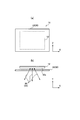
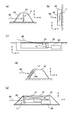
- FIG. 10 is a diagram showing an example of arrangement of the light reflecting device 11. As shown in this figure, a plurality (in other words, at least two) light reflecting devices 11 may be provided for one target position. Hereinafter, for convenience of explanation, a case where the number of the light reflecting devices 11 is 2 will be described as an example.
- the reflection setting device 30 such as the optical shutter 13 is omitted in FIG.
- the two light reflecting devices 11 when the two light reflecting devices 11 are projected on the XY plane (horizontal plane) along the Z direction (vertical direction), they are positioned at a predetermined distance from each other.
- the two light reflecting devices 11 are located on the XZ plane and are separated by a predetermined distance in the X direction.
- the two light reflecting devices 11 are located in the YZ plane and are separated by a predetermined distance in the Y direction.
- the heights of the two light reflectors 11 (retroreflectors 12) along the Z direction may be the same as shown in FIG. 10 (a), and are shown in FIGS. 10 (b) and 10 (c). It may be different as shown.
- the orientation of the vehicle with respect to the target position can be specified. For example, as shown in FIG. 10, it is assumed that two light reflecting devices 11 are arranged for one target position.
- the autonomous driving control unit 70 of the vehicle 50 identifies the position of the reflection point specified as each reflection surface 12a. Further, the autonomous driving control unit 70 specifies a direction connecting (passing) two reflection points as seen from the vehicle 50 (LIDAR60).
- this specified direction will be referred to as an arrangement direction.
- This arrangement direction is one of the tangential directions of the plane including the two reflection points.
- the plane including the two reflection points is a plane parallel to the XZ plane in FIGS. 10 (a) and 10 (b), and a plane parallel to the YZ plane in FIG. 10 (c). Therefore, the autonomous driving control unit 70 can specify the direction of the vehicle 50 with respect to the plane including the two reflection points based on the specified arrangement direction.
- the autonomous driving control unit 70 steers the specified vehicle 50 so that the specified direction is a predetermined direction.
- the predetermined orientation referred to here is included in, for example, a predetermined plane (for example, a horizontal plane or a traveling surface of the vehicle 50), and two reflection points are included.
- Autonomous driving may be controlled cruise called automatic driving. Further, since the autonomous driving according to the present disclosure is an operation toward a parking space, it may be a controlled driving called automatic parking.
Landscapes
- Engineering & Computer Science (AREA)
- Physics & Mathematics (AREA)
- General Physics & Mathematics (AREA)
- Remote Sensing (AREA)
- Radar, Positioning & Navigation (AREA)
- Computer Networks & Wireless Communication (AREA)
- Transportation (AREA)
- Mechanical Engineering (AREA)
- Power Engineering (AREA)
- Electromagnetism (AREA)
- Architecture (AREA)
- Multimedia (AREA)
- Signal Processing (AREA)
- Structural Engineering (AREA)
- Civil Engineering (AREA)
- Traffic Control Systems (AREA)
- Optical Radar Systems And Details Thereof (AREA)
Abstract
L'invention concerne un dispositif de guidage de véhicule (10) comprenant : au moins un dispositif réfléchissant la lumière (11) qui comprend un dispositif de rétroréflexion (12) qui réfléchit un faisceau laser de télémétrie (80) émis par un véhicule (50) afin d'effectuer une conduite autonome, et un dispositif de réglage de réflexion (30) qui définit soit un premier état dans lequel le faisceau laser (80) est rétroréfléchi vers le véhicule (50) par le dispositif de rétroréflexion (12), soit un second état dans lequel le faisceau laser (80) n'est pas rétroréfléchi vers le véhicule (50) par le dispositif de rétroréflexion (12); et une unité de commande (20) qui est associée au dispositif réfléchissant la lumière (11) et qui amène le dispositif de réglage de réflexion (30) à régler le premier état en fonction d'un réglage de position cible pour le véhicule (50), et qui amène le dispositif de réglage de réflexion (30) à régler le second état après que le véhicule (50) est arrivé à la position cible.
Priority Applications (3)
| Application Number | Priority Date | Filing Date | Title |
|---|---|---|---|
| JP2022515248A JP7384275B2 (ja) | 2020-04-17 | 2021-03-09 | 車両誘導装置、車両誘導方法及び駐車場 |
| DE112021002412.4T DE112021002412T5 (de) | 2020-04-17 | 2021-03-09 | Fahrzeugführungseinrichtung, Fahrzeugführungsverfahren und Parkbereich |
| US17/835,076 US11941982B2 (en) | 2020-04-17 | 2022-06-08 | Vehicle guidance device, vehicle guidance method and parking area |
Applications Claiming Priority (2)
| Application Number | Priority Date | Filing Date | Title |
|---|---|---|---|
| JP2020073802 | 2020-04-17 | ||
| JP2020-073802 | 2020-04-17 |
Related Child Applications (1)
| Application Number | Title | Priority Date | Filing Date |
|---|---|---|---|
| US17/835,076 Continuation US11941982B2 (en) | 2020-04-17 | 2022-06-08 | Vehicle guidance device, vehicle guidance method and parking area |
Publications (1)
| Publication Number | Publication Date |
|---|---|
| WO2021210302A1 true WO2021210302A1 (fr) | 2021-10-21 |
Family
ID=78085276
Family Applications (1)
| Application Number | Title | Priority Date | Filing Date |
|---|---|---|---|
| PCT/JP2021/009321 Ceased WO2021210302A1 (fr) | 2020-04-17 | 2021-03-09 | Dispositif de guidage de véhicule, procédé de guidage de véhicule et zone de stationnement |
Country Status (4)
| Country | Link |
|---|---|
| US (1) | US11941982B2 (fr) |
| JP (1) | JP7384275B2 (fr) |
| DE (1) | DE112021002412T5 (fr) |
| WO (1) | WO2021210302A1 (fr) |
Cited By (2)
| Publication number | Priority date | Publication date | Assignee | Title |
|---|---|---|---|---|
| JP7346659B1 (ja) | 2022-05-24 | 2023-09-19 | 株式会社ジャパン・インフラ・ウェイマーク | 移動体、制御方法、およびプログラム |
| JP2024087205A (ja) * | 2022-12-19 | 2024-07-01 | メルセデス・ベンツ グループ アクチェンゲゼルシャフト | 電動車両の駐車案内装置 |
Families Citing this family (2)
| Publication number | Priority date | Publication date | Assignee | Title |
|---|---|---|---|---|
| KR102506809B1 (ko) * | 2021-08-25 | 2023-03-06 | 고려대학교 산학협력단 | 무선 광통신 기반 장치 |
| US20230176217A1 (en) * | 2021-12-07 | 2023-06-08 | Beijing Voyager Technology Co., Ltd. | Lidar and ambience signal separation and detection in lidar receiver |
Citations (4)
| Publication number | Priority date | Publication date | Assignee | Title |
|---|---|---|---|---|
| JP2004116031A (ja) * | 2002-09-24 | 2004-04-15 | Japan System Bank Corp | ロック式駐車装置の故障時誤進入防止装置 |
| JP2014069647A (ja) * | 2012-09-28 | 2014-04-21 | Denso Corp | 駐車支援システム及び位置決め体付き輪止め |
| JP2015113600A (ja) * | 2013-12-10 | 2015-06-22 | 矢崎総業株式会社 | 駐車支援システム及びワイヤレス給電システム |
| JP2015158444A (ja) * | 2014-02-25 | 2015-09-03 | アイシン・エィ・ダブリュ株式会社 | 車両姿勢判定システム、車両姿勢判定プログラム及び車両姿勢判定方法 |
Family Cites Families (13)
| Publication number | Priority date | Publication date | Assignee | Title |
|---|---|---|---|---|
| ATE446563T1 (de) | 2007-04-26 | 2009-11-15 | Skidata Ag | Vorrichtung zur einzelstellplatzüberwachung |
| JP2013236524A (ja) | 2012-05-11 | 2013-11-21 | Mitsubishi Electric Corp | 非接触給電システム |
| USD729163S1 (en) | 2013-06-12 | 2015-05-12 | Bombardier Transportation Gmbh | Charging pad |
| JP6410080B2 (ja) | 2014-07-02 | 2018-10-24 | 株式会社デンソー | 非接触給電装置 |
| DE102014221746A1 (de) | 2014-10-27 | 2016-04-28 | Robert Bosch Gmbh | Verfahren und System zum Führen eines Fahrzeugs zu einem freien Stellplatz auf einem Parkplatz |
| JP6350312B2 (ja) | 2015-01-29 | 2018-07-04 | 株式会社デンソー | 非接触充電駐車支援装置 |
| US9625582B2 (en) * | 2015-03-25 | 2017-04-18 | Google Inc. | Vehicle with multiple light detection and ranging devices (LIDARs) |
| US10845470B2 (en) * | 2016-11-16 | 2020-11-24 | Waymo Llc | Methods and systems for protecting a light detection and ranging (LIDAR) device |
| JP6766690B2 (ja) | 2017-02-28 | 2020-10-14 | 株式会社Ihi | 地上側給電装置 |
| US11333748B2 (en) * | 2018-09-17 | 2022-05-17 | Waymo Llc | Array of light detectors with corresponding array of optical elements |
| US11353588B2 (en) * | 2018-11-01 | 2022-06-07 | Waymo Llc | Time-of-flight sensor with structured light illuminator |
| JP2020131943A (ja) | 2019-02-20 | 2020-08-31 | 住友電気工業株式会社 | 駐車制御システム、車載装置、駐車制御方法、及びコンピュータプログラム |
| US11557061B2 (en) * | 2019-06-28 | 2023-01-17 | GM Cruise Holdings LLC. | Extrinsic calibration of multiple vehicle sensors using combined target detectable by multiple vehicle sensors |
-
2021
- 2021-03-09 WO PCT/JP2021/009321 patent/WO2021210302A1/fr not_active Ceased
- 2021-03-09 DE DE112021002412.4T patent/DE112021002412T5/de active Pending
- 2021-03-09 JP JP2022515248A patent/JP7384275B2/ja active Active
-
2022
- 2022-06-08 US US17/835,076 patent/US11941982B2/en active Active
Patent Citations (4)
| Publication number | Priority date | Publication date | Assignee | Title |
|---|---|---|---|---|
| JP2004116031A (ja) * | 2002-09-24 | 2004-04-15 | Japan System Bank Corp | ロック式駐車装置の故障時誤進入防止装置 |
| JP2014069647A (ja) * | 2012-09-28 | 2014-04-21 | Denso Corp | 駐車支援システム及び位置決め体付き輪止め |
| JP2015113600A (ja) * | 2013-12-10 | 2015-06-22 | 矢崎総業株式会社 | 駐車支援システム及びワイヤレス給電システム |
| JP2015158444A (ja) * | 2014-02-25 | 2015-09-03 | アイシン・エィ・ダブリュ株式会社 | 車両姿勢判定システム、車両姿勢判定プログラム及び車両姿勢判定方法 |
Cited By (4)
| Publication number | Priority date | Publication date | Assignee | Title |
|---|---|---|---|---|
| JP7346659B1 (ja) | 2022-05-24 | 2023-09-19 | 株式会社ジャパン・インフラ・ウェイマーク | 移動体、制御方法、およびプログラム |
| JP2023172736A (ja) * | 2022-05-24 | 2023-12-06 | 株式会社ジャパン・インフラ・ウェイマーク | 移動体、制御方法、およびプログラム |
| JP2024087205A (ja) * | 2022-12-19 | 2024-07-01 | メルセデス・ベンツ グループ アクチェンゲゼルシャフト | 電動車両の駐車案内装置 |
| JP7551976B2 (ja) | 2022-12-19 | 2024-09-18 | メルセデス・ベンツ グループ アクチェンゲゼルシャフト | 電動車両の駐車案内装置 |
Also Published As
| Publication number | Publication date |
|---|---|
| DE112021002412T5 (de) | 2023-04-13 |
| JPWO2021210302A1 (fr) | 2021-10-21 |
| JP7384275B2 (ja) | 2023-11-21 |
| US20220301433A1 (en) | 2022-09-22 |
| US11941982B2 (en) | 2024-03-26 |
Similar Documents
| Publication | Publication Date | Title |
|---|---|---|
| JP7384275B2 (ja) | 車両誘導装置、車両誘導方法及び駐車場 | |
| JP6734951B2 (ja) | 複数の光検出及び測距装置(lidar)付きの車両 | |
| US20220308191A1 (en) | Use of Extended Detection Periods for Range Aliasing Detection and Mitigation in a Light Detection and Ranging (LIDAR) System | |
| CN111033306B (zh) | 通过多个假设的光探测和测距(lidar)设备范围混叠弹性 | |
| US11513525B2 (en) | Server and method for controlling laser irradiation of movement path of robot, and robot that moves based thereon | |
| JP2007527007A (ja) | 移動制御システム | |
| JP2019526056A (ja) | 車両の形状に適応したダイナミックステアドlidar | |
| JP2000162533A (ja) | 光走査装置 | |
| CN113167904B (zh) | 物体检测装置 | |
| CN105866737A (zh) | 具有自动定位系统的高安全性运输车 | |
| US20200191922A1 (en) | Measurement device | |
| KR20230118642A (ko) | 제어 방법 및 제어 시스템 | |
| KR102653633B1 (ko) | 무인 반송차 및 무인 반송차의 이동을 제어하기 위한 방법 | |
| CN213398918U (zh) | 激光雷达装置和agv小车 | |
| KR20240042394A (ko) | 무인 반송차 및 무인 반송차의 이동을 제어하기 위한 방법 | |
| JP2024161696A (ja) | 測量装置及び測量システム | |
| JP2025132579A (ja) | 給電システム | |
| WO2023181024A1 (fr) | Détermination de dimension d'objet à l'aide de grilles de pixels décalées | |
| JPH05187821A (ja) | 二重コ−ナキュ−ブと二重コ−ナキュ−ブを用いた移 動体の位置および姿勢計測法 |
Legal Events
| Date | Code | Title | Description |
|---|---|---|---|
| 121 | Ep: the epo has been informed by wipo that ep was designated in this application |
Ref document number: 21789209 Country of ref document: EP Kind code of ref document: A1 |
|
| ENP | Entry into the national phase |
Ref document number: 2022515248 Country of ref document: JP Kind code of ref document: A |
|
| 122 | Ep: pct application non-entry in european phase |
Ref document number: 21789209 Country of ref document: EP Kind code of ref document: A1 |