WO2021210360A1 - Dispositif de mesure, procédé de commande de dispositif de mesure et programme de commande de dispositif de mesure - Google Patents
Dispositif de mesure, procédé de commande de dispositif de mesure et programme de commande de dispositif de mesure Download PDFInfo
- Publication number
- WO2021210360A1 WO2021210360A1 PCT/JP2021/012013 JP2021012013W WO2021210360A1 WO 2021210360 A1 WO2021210360 A1 WO 2021210360A1 JP 2021012013 W JP2021012013 W JP 2021012013W WO 2021210360 A1 WO2021210360 A1 WO 2021210360A1
- Authority
- WO
- WIPO (PCT)
- Prior art keywords
- current
- phase
- voltage
- measurement system
- phases
- Prior art date
- Legal status (The legal status is an assumption and is not a legal conclusion. Google has not performed a legal analysis and makes no representation as to the accuracy of the status listed.)
- Ceased
Links
Images




Classifications
-
- G—PHYSICS
- G01—MEASURING; TESTING
- G01R—MEASURING ELECTRIC VARIABLES; MEASURING MAGNETIC VARIABLES
- G01R25/00—Arrangements for measuring phase angle between a voltage and a current or between voltages or currents
-
- G—PHYSICS
- G01—MEASURING; TESTING
- G01R—MEASURING ELECTRIC VARIABLES; MEASURING MAGNETIC VARIABLES
- G01R19/00—Arrangements for measuring currents or voltages or for indicating presence or sign thereof
- G01R19/25—Arrangements for measuring currents or voltages or for indicating presence or sign thereof using digital measurement techniques
- G01R19/2513—Arrangements for monitoring electric power systems, e.g. power lines or loads; Logging
-
- G—PHYSICS
- G01—MEASURING; TESTING
- G01R—MEASURING ELECTRIC VARIABLES; MEASURING MAGNETIC VARIABLES
- G01R29/00—Arrangements for measuring or indicating electric quantities not covered by groups G01R19/00 - G01R27/00
- G01R29/18—Indicating phase sequence; Indicating synchronism
Definitions
- the present invention relates to a measurement system, a measurement system control method, and a measurement system control program.
- Patent Document 1 device information for identifying a model of an electric device is acquired, current waveform data of a predetermined operating section is extracted, parameters used for identifying the electric device are extracted, and the electric device is described.
- a model identification system that identifies the model is described.
- Patent Document 2 describes a technique for determining an operating state of a power source by using a two-power metering method.
- the present invention has been made in view of the above circumstances, and is a measurement system capable of calculating changes in the current phases of three phases at low cost even when the rotation direction of the three-phase power is unknown.
- One purpose is to provide a measurement system control method and a measurement system control program.
- the measurement system of the embodiment is a line voltage of the first phase and the second phase of a three-phase power line composed of three phases of the first phase, the second phase and the third phase.
- a first voltage measuring unit that measures the first voltage
- a first current measuring unit that measures the first current that is the current of the first phase
- a third that measures the third current that is the current of the third phase.
- the current measuring unit, the determination unit that determines the rotation direction of the three phases based on the first voltage and the first current, and the first current, the third current, and the second phase based on at least the determination of the rotation direction by the determination unit. It is provided with a calculation unit for calculating the change in the current phase due to the load device at each of the second currents, which is the current of the above.
- the measurement system of the embodiment has a second voltage measuring unit that measures the second voltage, which is the line voltage between the second and third phases, and a determination unit based on the second voltage and the third current. It may further include a verification unit for verifying the rotation directions of the three phases determined in.
- the determination unit may determine an installation error of the third current measurement unit based on the verification result of the rotation direction.
- the determination unit may determine the rotation direction of the three phases based on the phase difference between the first voltage and the first current.
- an installation error of the third current measurement unit may be determined based on the verification result of the rotation direction.
- the determination unit rotates the three phases based on whether the phase of the first voltage is ahead of the phase of the first current or is behind the phase of the first current. It may determine the direction.
- the determination unit may determine the rotation direction of the three phases based on the power values calculated from the first voltage and the first current.
- the determination unit calculates from the first power value calculated from the first current whose phase is advanced from the first voltage and the first current whose phase is delayed from the first voltage.
- the second power value to be calculated may be calculated, and the rotation directions of the three phases may be determined based on the comparison of the magnitudes of the first power value and the second power value.
- the measurement system control method of the embodiment is a measurement system control method for controlling the measurement system, from the three phases of the first phase, the second phase, and the third phase.
- a first voltage measurement step for measuring the first voltage which is the line voltage between the first and second phases of the three-phase power line
- a first current measurement step for measuring the first current, which is the current for the first phase.
- a determination step of determining the rotation direction of the three phases based on the first voltage and the first current, and a calculation step of calculating the phase shift of the first current based on the determination of the rotation direction in the determination step are included.
- the measurement system control program of the embodiment is applied to the measurement system with the first phase and the first phase of the three-phase power line composed of the three phases of the first phase, the second phase and the third phase.
- the first voltage measurement function that measures the first voltage, which is the line voltage of the two phases
- the first current measurement function that measures the first current, which is the current of the first phase
- a determination function for determining the rotation direction of the three phases and a calculation function for calculating the phase shift of the first current based on the determination of the rotation direction in the determination function are realized.
- the measurement system is a first-phase and second-phase line voltage of a three-phase power line composed of three phases, a first phase, a second phase, and a third phase.
- One voltage is measured, the first current, which is the current of the first phase, is measured, the third current, which is the current of the third phase, is measured, and the rotation directions of the three phases are determined based on the first voltage and the first current.
- the three-phase power is determined by calculating the change in the current phase due to the load device in each of the first current, the third current, and the second current, which is the current of the second phase, based on at least the determination of the rotation direction. Even when the rotation direction is unknown, it is possible to calculate the change in the current phase for three phases at low cost.
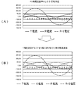
- the second determination method of the phase rotation direction in the measurement system of the embodiment is a waveform diagram explaining (A) the case where the power value is the maximum and (B) the case where the power value is the minimum. It is a flowchart which shows an example of the operation of the 2nd determination method of the phase rotation direction in the measurement system of embodiment.
- A a positive phase waveform based on the RS-phase voltage
- B a waveform for explaining the measurement waveform at the time of CT installation error. It is a figure.
- FIG. 1 is a block diagram showing an example of the configuration of the measurement system of the embodiment.
- the measurement system 10 includes a measurement device 1, a management device 2, a power meter P1, and a power meter P2.
- the measuring device 1 has a voltage measuring unit 11, a current measuring unit 12, and a communication control unit 13.
- the management device 2 includes a determination unit 21, a verification unit 22, a calculation unit 23, and a current analysis unit 24.
- the management device 2 is communicably connected to the management device 2 via the network 9.
- Each of the above-mentioned functional units of the measurement system 10 in the present embodiment will be described as a functional module realized by a measurement system control program (software) that controls the measurement system 10.
- the measurement system control program is executed by the measurement device 1 or the management device 2 in which each functional module is realized.
- the power supply 31 is a three-phase power supply including three phases of R phase, S phase and T phase.
- FIG. 1 power supply 31 illustrates a star-connected three-phase AC power supply having a neutral point N.
- the power supply 31 is connected to the load 32 by three wires, an R-phase wire, an S-phase wire, and an R-phase wire.
- the R phase may be referred to as the first phase
- the S phase may be referred to as the second phase
- the T phase may be referred to as the third phase.
- the first phase is not limited, and for example, any one of the S phase and the T phase may be used as the first phase.
- the power meter P1 has a first voltage measuring unit 111 and a first current measuring unit 121.
- the power meter P2 has a second voltage measuring unit 112 and a third current measuring unit 122.
- the first voltage measuring unit 111 may refer to the line voltage (“first voltage” or “RS line voltage”) between the R phase exemplified as the first phase and the S phase exemplified as the second phase. ) Measure the voltage waveform.
- the first current measuring unit 121 measures the current waveform of the R-phase line current (sometimes referred to as “first current” or “R-line current”).
- the second voltage measuring unit 112 measures the voltage waveform of the line voltage (TS line voltage) between the T phase and the S phase exemplified as the third phase.
- the third current measuring unit 122 measures the current waveform of the T-phase line current (sometimes referred to as “third current” or “T-line current”).
- the measured waveform data of the first voltage, the first current, the second voltage, and the third current are input to the measuring device 1.
- the voltage measuring unit 11 measures the voltage waveform measured by the first voltage measuring unit 111 and the second voltage measuring unit 112.
- the voltage measuring unit 11 may, for example, set a voltage waveform of the first voltage measured by the first voltage measuring unit 111 or the second voltage measured by the second voltage measuring unit 112 as a predetermined timing (sometimes referred to as sampling timing). ) Is sampled.
- the sampling timing is determined, for example, by a wavenumber counter (not shown) that counts the wavenumber in one second.
- the voltage measuring unit 11 measures the zero cross point based on the sampled voltage waveform.
- the zero cross point is a point when the voltage waveform becomes 0 V (sometimes referred to as “voltage 0 point”).
- the current measuring unit 12 measures the current waveforms of the first current measured by the first current measuring unit 121 and the third current measured by the third current measuring unit 122.
- the current measuring unit 12 samples, for example, the current waveform of the first current or the third current at the sampling timing.
- the current measuring unit 12 measures a zero cross point (sometimes referred to as “current 0 point”) based on the sampled current waveform.
- the communication control unit 13 controls the communication between the power meter P1 and the power meter P2 and the measuring device 1. Further, the communication control unit 13 controls communication with the management device 2 via the network 9.
- the communication control unit 13 may control either wired communication or wireless communication.
- the communication control unit 13 may control communication using a wireless LAN (Local Area Network) between the power meter P1 and the power meter P2. Further, the communication control unit 13 may control communication using the Internet protocol with the management device 2.
- LAN Local Area Network
- the management device 2 is a device capable of communicating with the measuring device 1 via the network 9, and is, for example, a server capable of communicating with a plurality of measuring devices 1.
- the determination unit 21 determines the rotation direction of the three phases of the power supply 31 based on the first voltage and the first current.
- the three-phase power supply has three phases of R phase, S phase, and T phase.
- the rotation direction of the three phases in the present embodiment is the transition direction of the three phases, and the voltage phases of the R phase, the S phase, and the T phase rotate (transition) in the order of RST.
- the rotation direction may be unknown before energization.
- the determination unit 21 enables correct measurement in the measurement system 10 by determining the rotation directions of the three phases even when the rotation directions of the three phases are unknown.
- the determination unit 21 determines the rotation direction of the three phases in at least one of the first determination method and the second determination method, which will be described later. If the direction of rotation can be determined, by measuring the voltage of one phase, the phase of the measured voltage waveform can be advanced or delayed by 120 degrees according to the direction of rotation without actually measuring the voltage of the other two phases. It is possible to calculate the voltage of the other two phases by performing the calculation.
- the rotation direction of RST is described as a positive phase and the rotation direction of TSR is a reverse phase, but the rotation direction of RST is a reverse phase and T. It may be carried out with the rotation direction of ⁇ SR as the positive phase.
- the verification unit 22 is a determination unit 21 based on the second voltage and the third current, which are the line voltages of the second phase (S phase) and the third phase (T phase) measured by the second voltage measurement unit 112. The determined rotation directions of the three phases are verified. The verification of the rotation direction is to verify whether or not the determination of the rotation direction determined by the determination unit 21 is correct. If the verification result does not contradict the judgment result, it is verified that the judgment result is correct. On the other hand, if the verification result contradicts the determination result, for example, an installation error of the third current measuring unit 122 is expected.
- the verification of the rotation direction by the verification unit 22 can be executed by the same method as the determination of the rotation direction by the determination unit 21.
- the verification by the verification unit 22 can also be executed by the same method as the first determination method. This makes it possible to share the algorithm, measurement data, and the like in the determination program used in the determination of the determination unit 21. The details of the verification method in the verification unit 22 will also be described later.
- the calculation unit 23 calculates the change in the current phase due to the load 32 in each of the first current, the third current, and the second current, which is the current of the second phase, based on at least the determination of the rotation direction by the determination unit 21. do.
- the change in the current phase due to the load 32 is the phase difference of the current with respect to the voltage in each phase due to the load 32.
- the load 32 is a load including an inductive reactance
- a delay in the current phase with respect to the voltage phase that is, a deterioration in the power factor occurs.
- the inductive reactance differs depending on the device, and the device included in the load 32 may be specified by calculating the phase change.
- the current analysis unit 24 analyzes the current of each phase.
- the current analysis unit 24 analyzes, for example, the type of equipment included in the load 32, the operating state of the equipment, and the like based on the current value, the current waveform, the phase difference from the voltage, and the like.
- the characteristics of each device that can be observed in the load current of the load 32 are stored in advance as a database, and the current analysis unit 24 compares the measured current waveform and the like with the database to determine the type of device and the like.
- the characteristics of each device include, for example, the current value, the change over time of the current value, the power factor, the shape of noise from the device mixed in the current line, and the like.
- the current analysis unit 24 may analyze the types of a plurality of devices by separating the features such as the measured current waveform for each device.
- each of the above-mentioned functional units of the measurement system 10 shows an example of the functional units of each device, and does not limit the functions of each device.
- the functional unit described as having the measuring device 1 may be implemented in the management device 2.
- the functional unit described as having the management device 2 may be implemented in the measuring device 1.
- each device does not have to have all the above-mentioned functional parts, and may have some functional parts.
- each device may have a function other than the above.
- each of the above-mentioned functional parts was explained as being realized by software. However, at least one or more of the functional units may be realized by hardware.
- any of the above functional units may be implemented by dividing one functional unit into a plurality of functional units. Further, any two or more of the above functional units may be integrated into one functional unit. That is, FIG. 1 shows the functions in the measurement system 10 expressed by functional blocks, and does not show, for example, that each functional unit is composed of a separate program file.
- each device may be a device realized by one housing or a system realized by a plurality of devices connected via a network or the like.
- the measuring device 1 or the management device 2 may realize a part or all of its functions by a virtual device such as a cloud service provided by a cloud computing system. That is, the measuring device 1 or the management device 2 may realize at least one or more of the above-mentioned functional units in another device.
- the measuring device 1 or the management device 2 may be a general-purpose computer such as a desktop PC or a server device, or may be a dedicated device having limited functions.
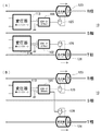
- FIG. 2 is a block diagram showing (A) a first example and (B) a block diagram showing a second example in the device configuration of the measurement system of the embodiment.
- the measurement system 10 includes a circuit meter 101, a circuit meter 102, a transformer 113, a transformer 114, a current transformer 123, a current transformer 124, a secondary current transformer 125, and a secondary current transformer. It has 126.
- the transformer 113 is a transformer that steps down the first voltage, which is the interphase voltage between the R phase (first phase) and the S phase (second phase), at a predetermined winding ratio.
- first voltage which is the interphase voltage between the R phase (first phase) and the S phase (second phase)
- second phase second phase
- one output line (L) is input to the circuit meter 101
- the other output line (N) is grounded and input to the circuit meter 101.
- the circuit meter 101 can measure the first voltage stepped down by the winding ratio of the transformer 113.
- the transformer 114 is a transformer that steps down the second voltage, which is the interphase voltage between the T phase (third phase) and the S phase (second phase), at a predetermined winding ratio.
- the second voltage which is the interphase voltage between the T phase (third phase) and the S phase (second phase)
- one output line (L) is input to the circuit meter 102
- the other output line (N) is grounded and input to the circuit meter 102.
- the circuit meter 102 can measure the first voltage stepped down by the winding ratio of the transformer 114.
- the current transformer 123 changes the current (first current) of the R phase (first phase).
- the secondary current transformer 125 changes the output current of the current transformer 123 to which the first current has been changed.
- the output current of the transformed secondary current transformer 125 is input to the circuit meter 101.
- the current transformer 124 changes the current (third current) of the T phase (third phase).
- the secondary current transformer 126 changes the output current of the current transformer 124 to which the third current has been changed.
- the output current of the transformed secondary current transformer 126 is input to the circuit meter 102. Further, the output current of the transformed secondary current transformer 126 is also input to the circuit meter 101.
- the S-phase current (second current) can be measured by the vector sum of the first current and the second current.
- the measurement system 10 shown in FIG. 2 (A) measures the waveforms of the RS phase voltage and the R phase current by measuring the first voltage (RS phase voltage) and the first current (R phase current). At the same time, it is possible to measure the waveforms of the TS phase voltage or the RS phase voltage and the T phase current by measuring the second voltage (TS phase voltage) and the third current (T phase current). can.
- the measurement system 10 includes a circuit meter 101, a transformer 113, a current transformer 123, a current transformer 124, a secondary current transformer 125, and a secondary current transformer 126. Note that the description overlapping with FIG. 2A may be omitted.
- the current transformer 124 changes the current (third current) of the T phase (third phase).
- the secondary current transformer 126 changes the output current of the current transformer 124 to which the third current has been changed.
- the output current of the transformed secondary current transformer 126 is input to the circuit meter 101. That is, the R-phase current and the T-phase current are input to the circuit meter 101.
- the measurement system 10 shown in FIG. 2B can measure the waveforms of the RS-phase voltage and the R-phase current by measuring the RS-phase voltage and the R-phase current, and also measures the T-phase current. Therefore, the waveforms of the RS-phase voltage and the T-phase current can be measured.
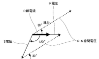
- FIG. 3 is a vector diagram illustrating a first example of the first determination method of the phase rotation direction in the measurement system of the embodiment.
- FIG. 3 shows a case where the rotation directions of the three phases are positive phases.
- the phase of the S voltage lags the phase of the R voltage by 120 degrees.
- the first voltage is an interphase voltage (RS voltage) between the R phase and the S phase.
- RS voltage interphase voltage
- the phase of the first voltage is 30 degrees ahead of the phase of the R-line current, which is the first current (the phase of the first current is It is 30 degrees behind the phase of the first voltage).
- the determination unit 21 compares the phase of the first voltage with the phase of the first current and determines that the phase of the first voltage is 30 degrees ahead of the phase of the first current. It can be determined that the rotation directions of the three phases are positive. For example, the determination unit 21 can determine that the phase of the first voltage is 30 degrees ahead of the phase of the first current by measuring the changes over time between the first voltage and the first current.
- the first determination method described above and the second determination method described later can also be carried out by the verification unit 22. That is, the verification unit 22 can determine the rotation directions of the three phases based on the first determination method or the second determination method. For example, in the above-described embodiment, the case where the rotation direction is determined by comparing the phases of the RS line voltage as the first voltage and the R current as the first current has been described, but the TS line voltage and the T current have been described.
- the first determination method can also be implemented in the phase comparison of. The rotation direction determined based on the RS line voltage and the first current coincides with the rotation direction determined based on the phase comparison between the TS line voltage and the T current. If the rotation directions do not match, there is a high possibility that the equipment has been installed incorrectly.
- the verification unit 22 determines, for example, by determining the rotation direction determined by the determination unit 21 based on the phases of the RS line voltage and the R current based on the phases of the TS line voltage and the T current. The determination result determined in the unit 21 can be verified.
- FIG. 4 is a waveform diagram illustrating a first example of the first determination method of the phase rotation direction in the measurement system of the embodiment.
- FIG. 4 is a waveform diagram showing the R voltage, the S voltage, the R current, and the RS voltage shown in FIG. 3 in time series. Similar to FIG. 3, the phase of the first voltage is 30 degrees ahead of the phase of the R line current which is the first current.
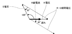
- FIG. 5 is a vector diagram illustrating a second example of the first determination method of the phase rotation direction in the measurement system 10 of the embodiment.
- FIG. 5 shows a case where the rotation directions of the three phases are opposite to each other.
- the S voltage advances 120 degrees from the R voltage. If there is no phase difference between the R-phase voltage and the R-phase current, the phase of the first voltage is 30 degrees behind the phase of the R-line current, which is the first current (the phase of the first current is the first). It is 30 degrees ahead of the voltage phase).
- the determination unit 21 compares the phase of the first voltage with the phase of the first current and determines that the phase of the first voltage is 30 degrees behind the phase of the first current, It can be determined that the rotation directions of the three phases are opposite phases.
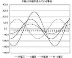
- FIG. 6 is a waveform diagram illustrating a second example of the first determination method of the phase rotation direction in the measurement system 10 of the embodiment.
- FIG. 6 is a waveform diagram showing the R voltage, the S voltage, the R current, and the RS voltage shown in FIG. 5 in time series. Similar to FIG. 5, the phase of the first voltage lags the phase of the R line current, which is the first current, by 30 degrees.
- the determination unit 21 can determine that the phase of the first voltage is 30 degrees behind the phase of the first current by measuring the changes over time between the first voltage and the first current.
- FIG. 7 is a flowchart showing an example of the operation of the first determination method in the phase rotation direction in the measurement system 10 of the embodiment.
- the execution subject of the process is the measurement system 10
- the operations shown in the flowchart are executed in each functional unit of the measurement system 10 described in FIG.
- the measurement system 10 obtains the positions of the 0 points (zero cross points) of the first voltage and the first current with the power meter P1 measuring the RS side (step S11).
- the determination unit 21 of the management device 2 has a voltage based on the voltage waveform measured by the first voltage measurement unit 111 of the wattmeter P1 and the current waveform measured by the first current measurement unit 121. The positions of the 0 point and the 0 point of the current can be obtained.
- the measurement system 10 After executing the process of step S11, the measurement system 10 compares the positions of the voltage 0 point of the first voltage and the current 0 point of the first current (step S12). It is determined whether or not the first current lags behind the first voltage by 30 degrees (step S13). When it is determined that the first current is delayed by 30 degrees (step S13: YES), the measurement system 10 determines that the rotation directions of the three phases are the positive phases of RST (step S14).
- the measurement system 10 After executing the process of step S14, the measurement system 10 obtains the position of the 0 point (zero cross point) of the second voltage and the third current with the power meter P2 measuring the TS side (step S15).
- the determination unit 21 of the management device 2 has a voltage based on the voltage waveform measured by the second voltage measurement unit 112 of the wattmeter P2 and the current waveform measured by the third current measurement unit 122. The positions of the 0 point and the 0 point of the current can be obtained.
- the measurement system 10 After executing the process of step S15, the measurement system 10 compares the positions of the voltage 0 point of the second voltage and the current 0 point of the third current (step S16). Next, the measurement system 10 determines whether or not the third current advances by 30 degrees with respect to the second voltage (step S17). When it is determined that the third current is advanced by 30 degrees (step S17: YES), the measurement system 10 determines that the rotation directions of the three phases are the positive phases of RST (step S18). Whether or not the determination result of the rotation direction determined in the process of step S14 is correct is verified in the process of step S18.
- step S17 NO
- the measurement system 10 determines that the equipment is installed incorrectly.
- the equipment installation error is, for example, an installation error of installing the current measuring unit in the T phase and the S phase, which should be originally installed in the T phase. Since the rotation direction of the three-phase electric wire cannot be confirmed unless it is confirmed with a measuring device in the energized state, the device may be mistakenly installed in a phase different from the originally installed phase. By verifying the direction of rotation, it is possible to determine an installation error.
- step S13 when it cannot be determined that the first current is delayed by 30 degrees (step S13: NO), the measurement system 10 determines that the rotation directions of the three phases are opposite phases of TSR. Judgment (step S20).
- the measurement system 10 After executing the process of step S20, the measurement system 10 obtains the position of the 0 point (zero cross point) of the second voltage and the third current with the power meter P2 measuring the TS side (step S21).
- the determination unit 21 of the management device 2 has a voltage based on the voltage waveform measured by the second voltage measurement unit 112 of the wattmeter P2 and the current waveform measured by the third current measurement unit 122. The positions of the 0 point and the 0 point of the current can be obtained.
- the measurement system 10 After executing the process of step S21, the measurement system 10 compares the positions of the voltage 0 point of the second voltage and the current 0 point of the third current (step S22). Next, the measurement system 10 determines whether or not the third current lags the second voltage by 30 degrees (step S23). When it is determined that the third current is delayed by 30 degrees (step S23: YES), the measurement system 10 determines that the rotation directions of the three phases are opposite phases of TSR (step S24). The determination result of the rotation direction determined in the process of step S20 is verified in the process of step S24.
- step S23 NO
- the measurement system 10 determines that the equipment is installed incorrectly.
- the measurement system 10 After executing the process of step S18, the process of step S19, the process of step S24, or the process of step S25, the measurement system 10 ends the operation shown in the flowchart.
- the second determination method calculates the power value based on the measured line voltage and line current, and determines the rotation direction from the phase relationship in which the power value is maximized from the calculated power values.
- the phase relationship between the RS line voltage and the R line current is based on the RS line voltage, and the phase difference of the R line current is +30 (whether the phase is delayed by 30 degrees) or the phase difference. Is either -30 degrees (whether the phase is advanced by 30 degrees).
- the phase relationship between the TS line voltage and the T line current is based on the TS line voltage, and the phase difference of the T line current is -30 (whether the phase is advanced by 30 degrees) or the phase difference is +30. It is either a degree (whether the phase is delayed by 30 degrees).
- the power value is obtained from the product of the line voltage and the line current at each of the above phase differences. That is, with respect to the RS line voltage, the power value when the phase difference is +30 degrees for the R line current and the power value when the phase difference is -30 degrees for the R line current are calculated, and the power value is large.
- the direction of rotation can be determined based on the phase difference between the two.
- the second determination method can be performed when the load power factor is about 0.9 or more (the phase difference between the line voltage and the line current is within about ⁇ 26 degrees).
- the rotation direction can also be verified in the second determination method. For example, the phase difference at which the power value becomes the maximum value is determined from the TS line voltage and the T line current, and the determination result is verified by checking whether or not the rotation direction matches the rotation direction determined from the TS line voltage and the T line current. can do.
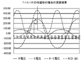
- FIG. 8 is a waveform diagram illustrating a first example of the calculation result of the first determination method in the phase rotation direction in the measurement system of the embodiment.
- FIG. 9 is a waveform diagram illustrating a second example of the calculation result of the first determination method in the phase rotation direction in the measurement system of the embodiment.
- FIG. 8 shows a case where the R-S line voltage is 30 degrees ahead of the R line current.
- the rotation direction of the three phases is the positive phase of the RS as described above.
- the power value obtained by multiplying the measured R-line current by six types of current waveforms whose phases are delayed by 30, 90, 150, 210, 270, and 330 degrees and the R-S line voltage.
- FIG. 9 shows a case where the voltage between the RS lines is delayed by 30 degrees from the R line current.
- the rotation directions of the three phases are opposite to those of the TS R as described above.
- Six types of current waveforms in which the measured R-line currents are delayed by 30, 90, 150, 210, 270, and 330 degrees are multiplied by the RS-line voltage to calculate the power value, and the six types of currents are calculated.
- the phase shift (power factor) between the phase voltage and the phase current affects the measurement.
- the phase difference at which the power value is maximized is not exactly ⁇ 30 degrees because the phase advance due to the power factor correction capacitor and the phase delay due to the motor load occur.
- load equipment in order to reduce power consumption, load equipment is designed so that the power factor during rated operation is as close to 1 as possible. Therefore, the correct phase relationship can be determined by long-time measurement for eliminating the influence of load fluctuation as much as possible, and by determining the phase relationship between both the RS side measurement and the TS side measurement. can. Further, by performing six kinds of calculations in which the phase of the current waveform is changed by 60 degrees as well as ⁇ 30 °, it is possible to detect an installation error during the sensor installation work.
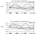
- FIG. 10 is a waveform diagram illustrating a first example of a second determination method in the phase rotation direction in the measurement system of the embodiment.
- the power measurement performs six types of operations in which the current phase is changed by 60 degrees.
- the absolute value of the power value is the largest among them. Two types of cases where the power is the smallest will be described as an example.
- FIG. 10 shows a method of detecting the phase relationship between the phase of the RS line voltage and the phase of the R current by the second determination method.
- FIG. 10A is a waveform diagram when the R-line current is advanced by 30 degrees (delayed by 330 degrees), and shows that the power value is 230.9 W, which is the maximum value among the six types.
- FIG. 10B is a waveform diagram when the R-line current is advanced by 90 degrees (delayed by 270 degrees), and shows that the absolute value of the power value is 115.5 W, which is the minimum value. Since the power value becomes maximum when the R line current is advanced by 30 degrees, it can be determined that the rotation direction is the positive phase of RST.
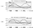
- FIG. 11 is a waveform diagram illustrating a second example of the second determination method of the phase rotation direction in the measurement system of the embodiment.
- FIG. 11 shows a method of detecting the phase relationship between the phase of the RS line voltage and the phase of the T current by the second determination method.
- FIG. 11A is a waveform diagram when the R-line current is advanced by 270 degrees (delayed by 90 degrees), and shows that the power value is 230.9 W, which is the maximum value among the six types. ..
- FIG. 11B is a waveform diagram when the T-line current is advanced by 330 degrees (delayed by 30 degrees), and shows that the absolute value of the power value is 115.5 W, which is the minimum value.
- the rotation direction is the positive phase of RST. For example, by performing the determination based on the T-phase current in FIG. 11 after the determination based on the R-phase current in FIG. 10, it is possible to verify the determination result based on the R-phase current.
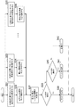
- FIG. 12 is a flowchart showing an example of the operation of the second determination method in the phase rotation direction in the measurement system 10 of the embodiment.
- the measurement system 10 executes the process of step S31 to the process of step S35 in parallel.
- the measurement system 10 measures the RS correlation voltage and the R current, and performs an operation of advancing the current waveform of the measured R current by 30 degrees (step S31).
- the measurement system 10 After executing the process of step S31, the measurement system 10 performs a vector product of the RS correlated voltage and the R current advanced by 30 degrees, and integrates them in one cycle to calculate the power value (step S32).
- the measurement system 10 performs an operation of advancing the current waveform of the measured R current by 90 degrees (step S33). After executing the process of step S33, the measurement system 10 performs a vector product of the RS correlated voltage and the R current advanced by 90 degrees, and integrates them in one cycle to calculate the power value (step S34). The measurement system 10 performs an operation of advancing the measured R current by 150 degrees, an operation of advancing by 210 degrees, and an operation of advancing by 270 degrees, which are not shown, and calculates each power value, and further, the current waveform of the measured R current. Is performed by 330 degrees (step S35), and the power value is calculated (step S36).
- the measurement system 10 After executing the processes of steps S32 to S36, the measurement system 10 obtains the phase relationship of the R current with respect to the RS correlation voltage that maximizes the power value (step S37). Next, the measurement system 10 determines whether or not the phase relationship is +30 degrees (step S38). When it is determined that the phase relationship is +30 degrees (step S38: YES), the measurement system 10 determines that the rotation directions of the three phases are the positive phases of RST (step S39).
- step S38 determines whether or not the phase relationship is +30 degrees (-30 degrees) (step S40).
- step S40 determines that the rotation directions of the three phases are opposite phases of TSR (step S41).
- step S40 determines that the equipment is installed incorrectly (step S42). That is, in the process of step S40, it is possible to verify the determination of the rotation direction in the process of step S39 by determining whether or not it contradicts the determination in the process of step S38.
- An example of measuring the waveform when it is determined that the device is installed incorrectly by the verification in the process of step S40 will be described with reference to FIGS. 13 to 14.
- step S39 After executing the process of step S39, step S41 or step S42, the measurement system 10 ends the operation shown in the flowchart.
- FIG. 13 shows, as the first example of the verification method of the phase rotation direction in the measurement system of the embodiment, (A) a positive phase waveform based on the RS-phase voltage, and (B) a measurement waveform when a CT is installed incorrectly. It is a waveform diagram explaining.
- FIG. 13 (A) is a waveform diagram of the R-S phase voltage, the R current, and the T current when the rotation direction is in the positive phase.
- the determination that the rotation direction is in the positive phase can be determined from the waveform data of the RS phase voltage and the R current.
- CT current measuring unit
- FIG. 13 (B) the waveform data of the S phase current is displayed instead of the T phase current. It will be measured. In this case, the rotation direction is judged inconsistent with the judgment result in the rotation direction verification.
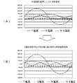
- FIG. 14 shows, as the first example of the method for verifying the phase rotation direction in the measurement system of the embodiment, (A) a reverse phase waveform based on the RS-phase voltage, and (B) a measurement waveform when a CT is installed incorrectly. It is a waveform diagram explaining.
- FIG. 14A is a waveform diagram of the R-S phase voltage, the R current, and the T current when the rotation directions are opposite to each other.
- the determination that the rotation directions are opposite to each other can be determined from the waveform data of the RS phase voltage and the R current.
- CT current measuring unit
- FIG. 14 (B) the waveform data of the S phase current is displayed instead of the T phase current. It will be measured. In this case, the rotation direction is judged inconsistent with the judgment result in the rotation direction verification.
- the program for realizing the function constituting the apparatus described in the present embodiment is recorded on a computer-readable recording medium, and the program recorded on the recording medium is read into the computer system and executed. Therefore, the above-mentioned various processes of the present embodiment may be performed.
- the "computer system” referred to here may include hardware such as an OS and peripheral devices. Further, the "computer system” includes a homepage providing environment (or a display environment) if a WWW system is used.
- the "computer-readable recording medium” includes a flexible disk, a magneto-optical disk, a ROM, a writable non-volatile memory such as a flash memory, a portable medium such as a CD-ROM, a hard disk built in a computer system, and the like. It refers to the storage device of.
- the "computer-readable recording medium” is a volatile memory inside a computer system that serves as a server or client when a program is transmitted via a network such as the Internet or a communication line such as a telephone line (for example, DRAM (Dynamic)). It also includes those that hold the program for a certain period of time, such as Random Access Memory)). Further, the program may be transmitted from a computer system in which this program is stored in a storage device or the like to another computer system via a transmission medium or by a transmission wave in the transmission medium.
- a network such as the Internet or a communication line such as a telephone line (for example, DRAM (Dynamic)). It also includes those that hold the program for a certain period of time, such as Random Access Memory)).
- the program may be transmitted from a computer system in which this program is stored in a storage device or the like to another computer system via a transmission medium or by a transmission wave in the transmission medium.
- the "transmission medium” for transmitting a program refers to a medium having a function of transmitting information, such as a network (communication network) such as the Internet or a communication line (communication line) such as a telephone line.
- the above program may be for realizing a part of the above-mentioned functions. Further, it may be a so-called difference file (difference program) that realizes the above-mentioned function in combination with a program already recorded in the computer system.
- Measuring device 10 Measuring system 101 Circuit meter 102 Circuit meter 11 Voltage measuring unit P1 Power meter P2 Power meter 111 1st voltage measuring unit 112 2nd voltage measuring unit 113 Transformer 114 Transformer 12 Current measuring unit 121 1st current measuring unit 122 Third current measuring unit 123 Current transformer 124 Current transformer 125 Secondary current transformer 126 Secondary current transformer 13 Communication control unit 2 Management device 21 Judgment unit 22 Verification unit 23 Calculation unit 24 Current analysis unit 31 Power supply 32 Load 9 network
Landscapes
- Physics & Mathematics (AREA)
- General Physics & Mathematics (AREA)
- Engineering & Computer Science (AREA)
- Power Engineering (AREA)
- Testing Of Short-Circuits, Discontinuities, Leakage, Or Incorrect Line Connections (AREA)
- Remote Monitoring And Control Of Power-Distribution Networks (AREA)
Abstract
L'invention concerne un système de mesure, un procédé de commande de système de mesure et un programme de commande de système de mesure permettant le calcul de changements de phases de courant de trois phases à faible coût, y compris lorsqu'un sens de rotation de puissance triphasée n'est pas connu. Un système de mesure selon un mode de réalisation est pourvu : d'une première unité de mesure de tension permettant de mesurer une première tension qui est une tension de ligne entre une première phase et une deuxième phase d'une ligne électrique triphasée comprenant trois phases, à savoir la première phase, la deuxième phase et une troisième phase ; d'une première unité de mesure de courant permettant de mesurer un premier courant qui est le courant de la première phase ; d'une troisième unité de mesure de courant permettant de mesurer un troisième courant qui est le courant de la troisième phase ; d'une unité de détermination permettant de déterminer un sens de rotation des trois phases sur la base de la première tension et du premier courant ; et d'une unité de calcul permettant de calculer des changements dans des phases de courant en raison d'un dispositif de charge dans le premier courant, le troisième courant, et un deuxième courant qui est le courant de la deuxième phase, sur la base d'au moins la détermination du sens de rotation obtenu par l'unité de détermination.
Priority Applications (2)
| Application Number | Priority Date | Filing Date | Title |
|---|---|---|---|
| EP21789214.0A EP4137823B1 (fr) | 2020-04-17 | 2021-03-23 | Dispositif de mesure, procédé de commande de dispositif de mesure et programme de commande de dispositif de mesure |
| US17/967,134 US12050238B2 (en) | 2020-04-17 | 2022-10-17 | Measurement device, measurement device control method, and measurement device control program |
Applications Claiming Priority (2)
| Application Number | Priority Date | Filing Date | Title |
|---|---|---|---|
| JP2020074379A JP7514466B2 (ja) | 2020-04-17 | 2020-04-17 | 計測装置、計測装置制御方法および計測装置制御プログラム |
| JP2020-074379 | 2020-04-17 |
Related Child Applications (1)
| Application Number | Title | Priority Date | Filing Date |
|---|---|---|---|
| US17/967,134 Continuation US12050238B2 (en) | 2020-04-17 | 2022-10-17 | Measurement device, measurement device control method, and measurement device control program |
Publications (1)
| Publication Number | Publication Date |
|---|---|
| WO2021210360A1 true WO2021210360A1 (fr) | 2021-10-21 |
Family
ID=78084255
Family Applications (1)
| Application Number | Title | Priority Date | Filing Date |
|---|---|---|---|
| PCT/JP2021/012013 Ceased WO2021210360A1 (fr) | 2020-04-17 | 2021-03-23 | Dispositif de mesure, procédé de commande de dispositif de mesure et programme de commande de dispositif de mesure |
Country Status (4)
| Country | Link |
|---|---|
| US (1) | US12050238B2 (fr) |
| EP (1) | EP4137823B1 (fr) |
| JP (1) | JP7514466B2 (fr) |
| WO (1) | WO2021210360A1 (fr) |
Citations (14)
| Publication number | Priority date | Publication date | Assignee | Title |
|---|---|---|---|---|
| JPS62162977A (ja) * | 1986-01-13 | 1987-07-18 | Matsushita Electric Ind Co Ltd | 位相計内蔵形電力管理計 |
| JPH0399370U (fr) * | 1990-01-31 | 1991-10-17 | ||
| JP2000074959A (ja) * | 1998-08-31 | 2000-03-14 | Matsushita Electric Ind Co Ltd | 電力計と電力量計 |
| JP2001124806A (ja) * | 1999-10-27 | 2001-05-11 | Mitsubishi Electric Corp | 三相電力測定器および三相電力量計ならびにその結線状態判別方法 |
| JP2004038765A (ja) * | 2002-07-05 | 2004-02-05 | Central Res Inst Of Electric Power Ind | 特定電気機器の動作状態推定方法及びシステム並びに電力需要家在室者の安否確認方法及びシステム並びに高調波信号注入装置を備えた電気機器 |
| JP2007212266A (ja) * | 2006-02-09 | 2007-08-23 | Nagoya Institute Of Technology | ビル用簡易型電力モニタリングシステム |
| JP2011072122A (ja) | 2009-09-25 | 2011-04-07 | Central Res Inst Of Electric Power Ind | 分散形電源の運転状態判別方法および装置並びに運転状態判別プログラム |
| US20160033568A1 (en) * | 2014-08-01 | 2016-02-04 | Metalligence Technology Corporation | Electronic device and detection method thereof |
| JP2016075587A (ja) * | 2014-10-07 | 2016-05-12 | 三菱電機株式会社 | 電力計測機器、および交流回路と電力計測機器との結線状態判別方法 |
| WO2016121378A1 (fr) * | 2015-01-28 | 2016-08-04 | 京セラ株式会社 | Dispositif de gestion d'énergie et dispositif de stockage d'énergie |
| US20160349311A1 (en) * | 2015-05-27 | 2016-12-01 | Eaton Corporation | Method and apparatus to commission voltage sensors and branch circuit current sensors for branch circuit monitoring systems |
| JP2018004330A (ja) * | 2016-06-28 | 2018-01-11 | 京セラ株式会社 | 電力管理装置、電流センサの設置方向の判定方法及び電力管理システム |
| US20190079117A1 (en) * | 2017-09-11 | 2019-03-14 | Analog Devices Global Unlimited Company | Current Measurement |
| JP2019053342A (ja) | 2016-01-21 | 2019-04-04 | インフォメティス株式会社 | 機種識別システム、機種識別方法、および、機種識別プログラム |
Family Cites Families (6)
| Publication number | Priority date | Publication date | Assignee | Title |
|---|---|---|---|---|
| US10613123B2 (en) * | 2013-05-15 | 2020-04-07 | The United States Of America As Represented By The Secretary Of The Army | Method and apparatus for power quality and synchrophasor monitoring on power lines |
| JP6435756B2 (ja) * | 2014-09-30 | 2018-12-12 | 富士通株式会社 | トランス接続相判定装置、方法、及びプログラム |
| EP3252907B1 (fr) * | 2015-01-29 | 2019-12-18 | Kyocera Corporation | Dispositif de commande de puissance et procédé de commande correspondant |
| US11054456B2 (en) * | 2017-09-18 | 2021-07-06 | Sensus Spectrum Llc | Systems and method for determining load balance on a three-phase power distribution system |
| CA3026918C (fr) * | 2017-12-14 | 2023-08-01 | Veris Industries, Llc | Compteur d'energie destine a un immeuble |
| US11249122B2 (en) * | 2019-08-27 | 2022-02-15 | Vertiv Corporation | Method and apparatus for providing automated power topology mapping |
-
2020
- 2020-04-17 JP JP2020074379A patent/JP7514466B2/ja active Active
-
2021
- 2021-03-23 WO PCT/JP2021/012013 patent/WO2021210360A1/fr not_active Ceased
- 2021-03-23 EP EP21789214.0A patent/EP4137823B1/fr active Active
-
2022
- 2022-10-17 US US17/967,134 patent/US12050238B2/en active Active
Patent Citations (14)
| Publication number | Priority date | Publication date | Assignee | Title |
|---|---|---|---|---|
| JPS62162977A (ja) * | 1986-01-13 | 1987-07-18 | Matsushita Electric Ind Co Ltd | 位相計内蔵形電力管理計 |
| JPH0399370U (fr) * | 1990-01-31 | 1991-10-17 | ||
| JP2000074959A (ja) * | 1998-08-31 | 2000-03-14 | Matsushita Electric Ind Co Ltd | 電力計と電力量計 |
| JP2001124806A (ja) * | 1999-10-27 | 2001-05-11 | Mitsubishi Electric Corp | 三相電力測定器および三相電力量計ならびにその結線状態判別方法 |
| JP2004038765A (ja) * | 2002-07-05 | 2004-02-05 | Central Res Inst Of Electric Power Ind | 特定電気機器の動作状態推定方法及びシステム並びに電力需要家在室者の安否確認方法及びシステム並びに高調波信号注入装置を備えた電気機器 |
| JP2007212266A (ja) * | 2006-02-09 | 2007-08-23 | Nagoya Institute Of Technology | ビル用簡易型電力モニタリングシステム |
| JP2011072122A (ja) | 2009-09-25 | 2011-04-07 | Central Res Inst Of Electric Power Ind | 分散形電源の運転状態判別方法および装置並びに運転状態判別プログラム |
| US20160033568A1 (en) * | 2014-08-01 | 2016-02-04 | Metalligence Technology Corporation | Electronic device and detection method thereof |
| JP2016075587A (ja) * | 2014-10-07 | 2016-05-12 | 三菱電機株式会社 | 電力計測機器、および交流回路と電力計測機器との結線状態判別方法 |
| WO2016121378A1 (fr) * | 2015-01-28 | 2016-08-04 | 京セラ株式会社 | Dispositif de gestion d'énergie et dispositif de stockage d'énergie |
| US20160349311A1 (en) * | 2015-05-27 | 2016-12-01 | Eaton Corporation | Method and apparatus to commission voltage sensors and branch circuit current sensors for branch circuit monitoring systems |
| JP2019053342A (ja) | 2016-01-21 | 2019-04-04 | インフォメティス株式会社 | 機種識別システム、機種識別方法、および、機種識別プログラム |
| JP2018004330A (ja) * | 2016-06-28 | 2018-01-11 | 京セラ株式会社 | 電力管理装置、電流センサの設置方向の判定方法及び電力管理システム |
| US20190079117A1 (en) * | 2017-09-11 | 2019-03-14 | Analog Devices Global Unlimited Company | Current Measurement |
Non-Patent Citations (1)
| Title |
|---|
| See also references of EP4137823A4 |
Also Published As
| Publication number | Publication date |
|---|---|
| EP4137823A4 (fr) | 2024-05-22 |
| EP4137823B1 (fr) | 2025-07-16 |
| US20230039083A1 (en) | 2023-02-09 |
| US12050238B2 (en) | 2024-07-30 |
| EP4137823A1 (fr) | 2023-02-22 |
| JP2021173526A (ja) | 2021-11-01 |
| JP7514466B2 (ja) | 2024-07-11 |
| EP4137823C0 (fr) | 2025-07-16 |
Similar Documents
| Publication | Publication Date | Title |
|---|---|---|
| US10823772B2 (en) | Generator waveform measurement | |
| Mirzaeva et al. | Advanced diagnosis of rotor faults and eccentricity in induction motors based on internal flux measurement | |
| US5488281A (en) | Method and apparatus for predicting winding failure using zero crossing times | |
| EP3598153B1 (fr) | Dispositif de détection de courant de fuite, méthode et programme de détection de courant de fuite | |
| CN108141169A (zh) | 用于识别机电系统的离散瞬时角速度的方法 | |
| US20170363664A1 (en) | Apparatus for and method of providing measurements of uncertainty in respect of a transfer function | |
| KR102079034B1 (ko) | 전류 공간 벡터와 푸리에 또는 웨이블릿 변환을 이용하여 유도 전동기의 회전자 결함 및 부하 결함을 진단하는 방법 및 장치 | |
| JP2007325429A (ja) | 回転位相角測定装置及びこれを用いた周波数測定装置、同期フェーザ測定装置、開閉極位相制御装置、同期投入装置及び相判別装置 | |
| US7720620B2 (en) | System and method for determining harmonic contributions from non-linear loads without disconnecting any load | |
| JP7509385B2 (ja) | 検出装置、方法およびプログラム | |
| WO2021210360A1 (fr) | Dispositif de mesure, procédé de commande de dispositif de mesure et programme de commande de dispositif de mesure | |
| Lewandowski et al. | Effective estimation of angular speed of synchronous generator based on stator voltage measurement | |
| WO1995019007A1 (fr) | Procede et systeme de prevision des conditions d'etat stable a partir de donnees cycliques ou monotoniques transitoires | |
| Kyriakides et al. | Estimation of synchronous generator parameters using an observer for damper currents and a graphical user interface | |
| Deleanu et al. | Performance evaluation of the three-phase induction motor operating in conditions of unbalanced voltage supply | |
| Hope et al. | Measurement of transfer functions of power system components under operating conditions | |
| JP7215226B2 (ja) | 接続相推定装置、接続相推定プログラム及び接続相推定方法 | |
| Badwaik et al. | Underground Cable Fault Detection System by Using IoT | |
| CA2510273A1 (fr) | Methode et systeme de detection de tension triphasee et de protection | |
| Saadat et al. | Assessment of Noise and Measurement Error Impact on Voltage Sag Source Location Methods | |
| McDonald et al. | Development of a technique for calculation of the influence of generator design on power system balanced fault behaviour | |
| CN116893383A (zh) | 一种配电终端的波形精度检测方法及装置 | |
| Cicilio et al. | Dynamic Composite Load Model Priority Placement Based on Electrical Centrality | |
| Khan et al. | Identification of Permanent Magnet Synchronous Motor Parameters | |
| Amrhein et al. | Power quality analysis framework for ac and dc electrical systems |
Legal Events
| Date | Code | Title | Description |
|---|---|---|---|
| 121 | Ep: the epo has been informed by wipo that ep was designated in this application |
Ref document number: 21789214 Country of ref document: EP Kind code of ref document: A1 |
|
| ENP | Entry into the national phase |
Ref document number: 2021789214 Country of ref document: EP Effective date: 20221117 |
|
| NENP | Non-entry into the national phase |
Ref country code: DE |
|
| WWG | Wipo information: grant in national office |
Ref document number: 2021789214 Country of ref document: EP |