WO2021210519A1 - Dispositif de commande de mouvement de véhicule et procédé de commande de mouvement de véhicule - Google Patents
Dispositif de commande de mouvement de véhicule et procédé de commande de mouvement de véhicule Download PDFInfo
- Publication number
- WO2021210519A1 WO2021210519A1 PCT/JP2021/015109 JP2021015109W WO2021210519A1 WO 2021210519 A1 WO2021210519 A1 WO 2021210519A1 JP 2021015109 W JP2021015109 W JP 2021015109W WO 2021210519 A1 WO2021210519 A1 WO 2021210519A1
- Authority
- WO
- WIPO (PCT)
- Prior art keywords
- curve
- traveling
- curvature
- motion control
- vehicle
- Prior art date
- Legal status (The legal status is an assumption and is not a legal conclusion. Google has not performed a legal analysis and makes no representation as to the accuracy of the status listed.)
- Ceased
Links
Images






Classifications
-
- B—PERFORMING OPERATIONS; TRANSPORTING
- B60—VEHICLES IN GENERAL
- B60W—CONJOINT CONTROL OF VEHICLE SUB-UNITS OF DIFFERENT TYPE OR DIFFERENT FUNCTION; CONTROL SYSTEMS SPECIALLY ADAPTED FOR HYBRID VEHICLES; ROAD VEHICLE DRIVE CONTROL SYSTEMS FOR PURPOSES NOT RELATED TO THE CONTROL OF A PARTICULAR SUB-UNIT
- B60W60/00—Drive control systems specially adapted for autonomous road vehicles
- B60W60/001—Planning or execution of driving tasks
-
- B—PERFORMING OPERATIONS; TRANSPORTING
- B60—VEHICLES IN GENERAL
- B60W—CONJOINT CONTROL OF VEHICLE SUB-UNITS OF DIFFERENT TYPE OR DIFFERENT FUNCTION; CONTROL SYSTEMS SPECIALLY ADAPTED FOR HYBRID VEHICLES; ROAD VEHICLE DRIVE CONTROL SYSTEMS FOR PURPOSES NOT RELATED TO THE CONTROL OF A PARTICULAR SUB-UNIT
- B60W30/00—Purposes of road vehicle drive control systems not related to the control of a particular sub-unit, e.g. of systems using conjoint control of vehicle sub-units
- B60W30/08—Active safety systems predicting or avoiding probable or impending collision or attempting to minimise its consequences
- B60W30/095—Predicting travel path or likelihood of collision
- B60W30/0956—Predicting travel path or likelihood of collision the prediction being responsive to traffic or environmental parameters
-
- B—PERFORMING OPERATIONS; TRANSPORTING
- B60—VEHICLES IN GENERAL
- B60W—CONJOINT CONTROL OF VEHICLE SUB-UNITS OF DIFFERENT TYPE OR DIFFERENT FUNCTION; CONTROL SYSTEMS SPECIALLY ADAPTED FOR HYBRID VEHICLES; ROAD VEHICLE DRIVE CONTROL SYSTEMS FOR PURPOSES NOT RELATED TO THE CONTROL OF A PARTICULAR SUB-UNIT
- B60W30/00—Purposes of road vehicle drive control systems not related to the control of a particular sub-unit, e.g. of systems using conjoint control of vehicle sub-units
- B60W30/02—Control of vehicle driving stability
- B60W30/045—Improving turning performance
-
- B—PERFORMING OPERATIONS; TRANSPORTING
- B60—VEHICLES IN GENERAL
- B60W—CONJOINT CONTROL OF VEHICLE SUB-UNITS OF DIFFERENT TYPE OR DIFFERENT FUNCTION; CONTROL SYSTEMS SPECIALLY ADAPTED FOR HYBRID VEHICLES; ROAD VEHICLE DRIVE CONTROL SYSTEMS FOR PURPOSES NOT RELATED TO THE CONTROL OF A PARTICULAR SUB-UNIT
- B60W30/00—Purposes of road vehicle drive control systems not related to the control of a particular sub-unit, e.g. of systems using conjoint control of vehicle sub-units
- B60W30/10—Path keeping
-
- B—PERFORMING OPERATIONS; TRANSPORTING
- B60—VEHICLES IN GENERAL
- B60W—CONJOINT CONTROL OF VEHICLE SUB-UNITS OF DIFFERENT TYPE OR DIFFERENT FUNCTION; CONTROL SYSTEMS SPECIALLY ADAPTED FOR HYBRID VEHICLES; ROAD VEHICLE DRIVE CONTROL SYSTEMS FOR PURPOSES NOT RELATED TO THE CONTROL OF A PARTICULAR SUB-UNIT
- B60W30/00—Purposes of road vehicle drive control systems not related to the control of a particular sub-unit, e.g. of systems using conjoint control of vehicle sub-units
- B60W30/18—Propelling the vehicle
- B60W30/18009—Propelling the vehicle related to particular drive situations
- B60W30/18145—Cornering
-
- B—PERFORMING OPERATIONS; TRANSPORTING
- B60—VEHICLES IN GENERAL
- B60W—CONJOINT CONTROL OF VEHICLE SUB-UNITS OF DIFFERENT TYPE OR DIFFERENT FUNCTION; CONTROL SYSTEMS SPECIALLY ADAPTED FOR HYBRID VEHICLES; ROAD VEHICLE DRIVE CONTROL SYSTEMS FOR PURPOSES NOT RELATED TO THE CONTROL OF A PARTICULAR SUB-UNIT
- B60W40/00—Estimation or calculation of non-directly measurable driving parameters for road vehicle drive control systems not related to the control of a particular sub unit, e.g. by using mathematical models
- B60W40/02—Estimation or calculation of non-directly measurable driving parameters for road vehicle drive control systems not related to the control of a particular sub unit, e.g. by using mathematical models related to ambient conditions
- B60W40/06—Road conditions
- B60W40/072—Curvature of the road
-
- B—PERFORMING OPERATIONS; TRANSPORTING
- B60—VEHICLES IN GENERAL
- B60W—CONJOINT CONTROL OF VEHICLE SUB-UNITS OF DIFFERENT TYPE OR DIFFERENT FUNCTION; CONTROL SYSTEMS SPECIALLY ADAPTED FOR HYBRID VEHICLES; ROAD VEHICLE DRIVE CONTROL SYSTEMS FOR PURPOSES NOT RELATED TO THE CONTROL OF A PARTICULAR SUB-UNIT
- B60W2520/00—Input parameters relating to overall vehicle dynamics
- B60W2520/06—Direction of travel
-
- B—PERFORMING OPERATIONS; TRANSPORTING
- B60—VEHICLES IN GENERAL
- B60W—CONJOINT CONTROL OF VEHICLE SUB-UNITS OF DIFFERENT TYPE OR DIFFERENT FUNCTION; CONTROL SYSTEMS SPECIALLY ADAPTED FOR HYBRID VEHICLES; ROAD VEHICLE DRIVE CONTROL SYSTEMS FOR PURPOSES NOT RELATED TO THE CONTROL OF A PARTICULAR SUB-UNIT
- B60W2552/00—Input parameters relating to infrastructure
- B60W2552/20—Road profile, i.e. the change in elevation or curvature of a plurality of continuous road segments
-
- B—PERFORMING OPERATIONS; TRANSPORTING
- B60—VEHICLES IN GENERAL
- B60W—CONJOINT CONTROL OF VEHICLE SUB-UNITS OF DIFFERENT TYPE OR DIFFERENT FUNCTION; CONTROL SYSTEMS SPECIALLY ADAPTED FOR HYBRID VEHICLES; ROAD VEHICLE DRIVE CONTROL SYSTEMS FOR PURPOSES NOT RELATED TO THE CONTROL OF A PARTICULAR SUB-UNIT
- B60W2552/00—Input parameters relating to infrastructure
- B60W2552/30—Road curve radius
-
- B—PERFORMING OPERATIONS; TRANSPORTING
- B60—VEHICLES IN GENERAL
- B60W—CONJOINT CONTROL OF VEHICLE SUB-UNITS OF DIFFERENT TYPE OR DIFFERENT FUNCTION; CONTROL SYSTEMS SPECIALLY ADAPTED FOR HYBRID VEHICLES; ROAD VEHICLE DRIVE CONTROL SYSTEMS FOR PURPOSES NOT RELATED TO THE CONTROL OF A PARTICULAR SUB-UNIT
- B60W2552/00—Input parameters relating to infrastructure
- B60W2552/53—Road markings, e.g. lane marker or crosswalk
Definitions
- the present invention relates to a vehicle motion control device and a vehicle motion control method that generate a travel track that is a travel target of a vehicle and control the motion of the vehicle based on the generated travel track.
- a running track composed of information such as a running path and a running speed, which is a running target of the vehicle, is generated, and a power train is used so that the vehicle follows the generated running track.
- a power train is used so that the vehicle follows the generated running track.
- Brake, steering, etc. are known to be controlled.
- the simplest driving route is the one in which the center of the lane is the driving route.
- Patent Document 1 Japanese Patent Application Laid-Open No. 2017-100652
- Patent Document 1 whether or not there is a curved path defined by the radius of curvature in the path range preset in the traveling direction from the current position of the vehicle among the lane traveling paths indicating the center of the preset lane.
- the curved route and the locus corresponding to the planned traveling locus is set as the cornering line, and the cornering line of the cornering line.
- a traveling locus generator that generates a planned traveling locus is described so that the radius of curvature is larger than the radius of curvature of the curved path (see summary).
- the traveling locus generator described in Patent Document 1 creates a planned traveling locus so that the radius of curvature of the cornering line (traveling path when traveling on a curve) is larger than the radius of curvature of the curved path (road shape). It is generated to improve the riding comfort of the vehicle.
- the traveling locus generator described in Patent Document 1 always generates a planned traveling locus so that the radius of curvature of the traveling path when traveling on a curve is larger than the radius of curvature of the road shape.
- the start point and end point of the planned travel trajectory of one curve are outside the lane travel path.
- connection point of a continuous curve where the distance between curves is restricted it is necessary to connect two points outside the lane driving path, and the degree of freedom of the planned traveling trajectory that can be generated is limited. It may be smaller.
- the traveling locus generator described in Patent Document 1 may be able to generate only a traveling path having a radius of curvature that is almost the same as that of a traveling path in the center of the lane, and a necessary and sufficient vehicle ride. You may not feel comfortable.
- a vehicle motion control device and a vehicle motion control method for generating a traveling route to be driven.
- the vehicle motion control device of the present invention is based on information on the curvature of the first curve on the lane existing in the traveling direction of the vehicle and the second curve connected to the first curve.
- the curvature of the traveling path when traveling on the curve with the smaller curvature is set to be larger than the curvature of the curve, and the curvature of the traveling path when traveling on the curve with the larger curvature is set.
- It is characterized by having a traveling track generation unit that is set smaller than the curvature of the curve and generates a traveling path.
- the vehicle motion control method of the present invention is based on information on the curvatures of the first curve on the lane existing in the traveling direction of the vehicle and the second curve connected to the first curve.
- the traveling track generation unit that generates a traveling path
- the curvature of the traveling path when traveling on the curve having the smaller curvature among the first curve and the second curve is set to be larger than the curvature of the curve, and the curvature is set.
- the curvature of the traveling path when traveling on the larger curve is set to be smaller than the curvature of the curve.
- the present invention even when traveling on a continuous curve in which the distance between curves is restricted, the behavior of the vehicle while traveling on the curve (during turning) is small, and a comfortable ride is realized. It is possible to provide a vehicle motion control device and a vehicle motion control method for generating a traveling route.
- FIG. It is explanatory drawing explaining the structure of the vehicle-mounted system 1 which has the vehicle motion control device 2 described in Example 1.
- FIG. It is explanatory drawing explaining the functional block of the traveling track generation unit 22 described in Example 1.
- FIG. It is a flowchart explaining the processing outline of the route planning part 22d described in Example 1.
- FIG. It is explanatory drawing explaining the traveling route of the 1st example described in Example 1.
- FIG. It is explanatory drawing explaining the curvature at the time of traveling on the traveling path of 1st Example described in Example 1.
- FIG. It is explanatory drawing explaining the yaw rate at the time of traveling on the traveling path of 1st Example described in Example 1.
- FIG. It is explanatory drawing explaining the lateral acceleration at the time of traveling on the traveling path of 1st Example described in Example 1.
- FIG. It is explanatory drawing explaining the lateral acceleration when traveling on the traveling path of 1st Example described in Example 1.
- FIG. It is explanatory drawing explaining the traveling route of the 2nd Example described in Example 1.
- FIG. It is explanatory drawing explaining the curvature at the time of traveling on the traveling path of the 2nd Example described in Example 1.
- FIG. It is explanatory drawing explaining the yaw rate at the time of traveling on the traveling path of the 2nd Example described in Example 1.
- FIG. It is explanatory drawing explaining the lateral acceleration at the time of traveling on the traveling path of the 2nd Example described in Example 1.
- FIG. It is explanatory drawing explaining the lateral acceleration when traveling on the traveling path of the 2nd example described in Example 1.
- FIG. It is explanatory drawing explaining the functional block of the traveling track generation unit 22 described in Example 2.
- FIG. It is explanatory drawing explaining the functional block of the traveling track generation unit 22 described in Example 2.
- FIG. 1 is an explanatory diagram illustrating a configuration of an in-vehicle system 1 having the vehicle motion control device 2 described in the first embodiment.
- the in-vehicle system 1 includes an external communication device 11, a GNSS (Global Navigation Satellite System) 12, a map information storage unit 13, a sensor 14, an HMI (human machine interface) unit 15, a vehicle motion control device 2, a power train system 3, and a braking system. 4. Has a stelling system 5.
- GNSS Global Navigation Satellite System
- HMI human machine interface
- the in-vehicle system 1 is mounted on the vehicle and executes vehicle motion control such as automatic driving of the vehicle and driving support.
- the out-of-vehicle communication device 11 executes vehicle-to-vehicle communication with another vehicle or road-to-vehicle communication with a roadside unit by wireless communication, and transmits / receives information such as a vehicle and the surrounding environment.
- the GNSS12 receives radio waves transmitted from artificial satellites such as the quasi-zenith satellite and the GPS (Global Positioning System) satellite, and acquires information such as the position of the vehicle (own vehicle).
- artificial satellites such as the quasi-zenith satellite and the GPS (Global Positioning System) satellite
- GPS Global Positioning System
- the map information storage unit 13 includes general road information used in a navigation system or the like, road information having information on curves such as road width and road curvature, information such as road surface condition and traffic condition, and other vehicles. It stores information such as the vehicle and the surrounding environment, which is information on the driving condition. Information such as the vehicle and the surrounding environment is sequentially updated by the information acquired by the vehicle-to-vehicle communication and the road-to-vehicle communication via the vehicle-external communication device 11.
- the sensor 14 includes an image sensor, a millimeter-wave radar, an outside world recognition sensor that detects information on the vehicle such as a rider and the surrounding environment, operation by a driver, vehicle speed, acceleration, jerk, angular velocity, wheel steering angle, and the like. It is a sensor that detects information.
- Information such as the vehicle and the surrounding environment detected by the outside world recognition sensor is, for example, various objects such as obstacles, signs, lane boundaries, lane outside lines, buildings, pedestrians, and other vehicles existing around the own vehicle. Information. Further, the sensor 14 recognizes a lane boundary line, a lane outside line, or the like, for example, based on the difference between the white line of the image data captured by the image sensor and the brightness of the road surface.
- the HMI unit 15 has information received by user input operations such as selection of a traveling mode and setting of a destination, information acquired by an external communication device 11, GNSS 12, and a sensor 14, and information recorded in a map information storage unit 13.
- the information required by the user is displayed on the display and voice guidance is provided from the speaker.
- the HMI unit 15 generates an alarm to alert the user.
- the driving mode includes, for example, a comfort mode, an economy mode, a sports mode, and the like, and the driving mode is arbitrarily set by the user, set in advance by the user, or described later based on the driving situation information.
- the speed, acceleration, jerk, etc. of the vehicle are set by the operation management unit 21 of the vehicle. That is, the upper limit of the behavior of the vehicle changes depending on the traveling mode.
- the traveling mode includes the shortest time mode that minimizes the travel time and the shortest distance mode that minimizes the travel distance.
- the vehicle motion control device 2 includes an operation management unit 21, a travel track generation unit 22, and a travel control unit 23.
- the operation management unit 21, the travel track generation unit 22, and the travel control unit 23 have hardware such as a computing device such as a CPU (Central Processing Unit), a main storage device such as a semiconductor memory, an auxiliary storage device, and a communication device.
- a computing device such as a CPU (Central Processing Unit)
- main storage device such as a semiconductor memory
- auxiliary storage device such as a semiconductor memory
- a communication device such as a communication device.
- it is a computer that controls the vehicle in an integrated manner, and realizes various functions by executing a program loaded in the main storage device by the arithmetic unit.
- the operation management unit 21, the traveling track generation unit 22, and the traveling control unit 23 have separate configurations, but they do not necessarily have to have separate configurations, and these units are actually used. When used in a vehicle, various functions of these units may be realized by a higher-level controller.
- the operation management unit 21 is based on the information acquired by the external communication device 11, the GNSS 12, and the sensor 14 and the information recorded in the map information storage unit 13, the information on the position of the own vehicle, and various types existing around the own vehicle. It generates information on the behavior of the vehicle such as object information (information on the vehicle and surrounding environment), lateral acceleration, yaw rate, and lateral acceleration.
- the information on the behavior of the vehicle is generated based on the information on the curve on the route and the information on the speed when traveling on the curve on the route.
- the operation management unit 21 periodically transmits information on the position of the own vehicle, information on various objects, and information on the behavior of the vehicle to other vehicles and roadside units via the external communication device 11. , The information is transmitted to the map information storage unit 13 and the information stored in the map information storage unit 13 is sequentially updated.
- the operation management unit 21 is based on the information on the position of the own vehicle, the information on various objects, the information on the behavior of the vehicle, and the information received by the HMI unit 15 (for example, the traveling mode and the destination). Set the route information from the current position to the destination.
- the information generated or set by the exercise management unit 21 may be referred to as “driving status information”.
- the traveling track generation unit 22 inputs travel status information, and has a traveling route (a traveling target route when the vehicle travels on the road) and a traveling speed (traveling when the vehicle travels on the road) as a traveling target of the vehicle. Generates a traveling track composed of information such as (target speed).
- the travel control unit 23 sets a target driving force, a target braking force, a target steering angle, and the like so that the vehicle travels following the travel track output from the travel track generation unit 22, and the power train system 3 It controls the brake system 4 and the steering system 5.
- the power train system 3 controls the driving force generated by the internal combustion engine, the electric motor, or the like based on the operation by the driver or the target driving force output from the traveling control unit 23.
- the brake system 4 controls the braking force generated by the brake caliper or the like based on the operation by the driver or the target braking force output from the travel control unit 23.
- the steering system 5 controls the steering angle of the wheels based on the operation by the driver and the target steering angle output from the travel control unit 23.
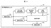
- FIG. 2 is an explanatory diagram illustrating a functional block of the traveling track generation unit 22 described in the first embodiment.
- the traveling track generation unit 22 inputs travel status information and generates a traveling track composed of information such as a traveling route and a traveling speed which is a traveling target of the vehicle. It has a travelable area calculation unit 22c, a route planning unit 22d, a nearest neighbor point calculation unit 22e, a route determination unit 22f, and a speed planning unit 22g.
- the information acquisition unit 22a acquires and outputs travel status information from the operation management unit 21.
- the road determination unit 22b inputs the traveling condition information, and the curvature of a plurality of (two or more) curves on the lane existing in the traveling direction of the vehicle is constant, or the road shape has a peak or an inflection point. (Curve shape) is determined as one curve, the number of curves (information) existing in the traveling direction of the vehicle is detected, and the length, width, and length of each detected curve are detected. Defines (acquires) information about curves such as curvature, turning direction, start point, and end point, and outputs it.
- peak curvature the curvature of one curve that is constant or forms a peak or an inflection point.
- the travelable area calculation unit 22c inputs travel status information and determines a travelable area in which the vehicle can travel without contacting obstacles, pedestrians, buildings, other vehicles, etc. existing in the traveling direction of the vehicle. Calculate and output.
- the travelable area calculation unit 22c calculates the risk potential map in consideration of the movement range of other vehicles and the reachable range in the behavior of pedestrians (for example, jumping out on the road), and outputs the risk potential map as the travelable area. You may.
- the route planning unit 22d inputs travel status information, curve information, and determination result (information) to generate a travel route.
- the nearest proximity point calculation unit 22e inputs a travelable area output from the travelable area calculation unit 22c and a travel path output from the route planning unit 22d, and each point in the travel path and each in the travelable area.
- the nearest point and the point facing the nearest point are searched, the distance between each point and the nearest point of each point, and the distance between each point and the point facing the nearest point are calculated and output.
- the travelable area is information having a predetermined width
- a plurality of pair of reference points can be plotted on both sides of the travelable area with a predetermined interval.
- the left side of the travelable area has a plurality of reference points with a predetermined interval
- the right side of the travelable area has a plurality of reference points with a predetermined interval. That is, a pair is formed by the reference point on the left side and the reference point on the right side.
- the nearest reference point (first nearest neighbor point) with respect to a certain point existing on the traveling path is searched, and the reference point paired with the nearest reference point (opposing the first nearest neighbor point). Search for a point (second neighbor point).
- the nearest reference point with respect to a certain point existing on the traveling path is referred to as “nearest neighbor point A”, and is referred to as the nearest reference point.
- the paired reference points may be referred to as “nearest neighbor points B”.
- the nearest neighbor point calculation unit 22e is between a certain point and the nearest neighbor point A, a distance from the certain point to the nearest neighbor point B, and the nearest neighbor point A and the nearest neighbor point B existing on the traveling path. The distance is calculated and output for each point existing on the travel path.
- the travelable area is information having a predetermined width, but there is a possibility that the travelable area does not have a width depending on the position of obstacles, pedestrians, buildings, other vehicles, the speed of the vehicle, and the like.
- the nearest neighbor point calculation unit 22e treats the nearest neighbor point A and the nearest neighbor point B as the same point, and calculates the distance.
- the route determination unit 22f is output from the nearest neighbor point calculation unit 22e, exists on the travel path, the distance from each point to each nearest neighbor point A, the distance from each point to each nearest neighbor point B, and each recent The distance between the emphasis marks A and the nearest neighbor points B is input, it is determined whether or not the traveling route is within the travelable area, and the determination result (information) is output.
- the distance from the one point existing on the traveling path to the nearest point A and the distance from this one point to the nearest point B The sum of and the distance must be equal to the distance between the nearest point A and the nearest point B.
- the speed planning unit 22g inputs the traveling status information and the traveling route output from the route planning unit 22d, sets the speed (traveling speed) at each point existing on the traveling route, and sets the traveling speed (traveling speed) as the traveling track as the traveling control unit 23. Output to.
- the speed planning unit 22g sets the traveling speed at each point existing on the traveling path so as to be equal to or less than the upper limit value of the vehicle behavior. do.
- the speed planning unit 22g calculates the behavior of the vehicle that occurs when traveling on the traveling route, sets the traveling speed so as to be equal to or less than the upper limit of the behavior of the vehicle set by the traveling mode, and sets the traveling track. To generate.
- FIG. 3 is a flowchart illustrating a processing outline of the route planning unit 22d described in the first embodiment.
- step S101 the traveling condition information output from the information acquisition unit 22a, the number of curves (information) existing in the traveling direction of the vehicle output from the road determination unit 22b, the length of each detected curve, Acquires information on curves such as width, curvature (peak curvature), turning direction, start point, end point, and determination result (information) of whether or not the travel path output from the route determination unit 22f is within the travelable area. .. Then, the process proceeds to step S102.
- step S102 it is determined whether or not the traveling route is outside the travelable area based on the determination result (information) acquired in step S101.
- step S103 If the travel route is outside the travelable area (YES), the process proceeds to step S103.
- step S102 is a step when a traveling route within the travelable area has already been set, and when the travel route within the travelable area has not yet been set, step S102 is skipped.
- step S103 it is determined whether or not the number of curves is more than one based on the number of curves (information) existing in the traveling direction of the vehicle acquired in step S101.
- step S104 If the number of curves is one (NO), the process proceeds to step S104.
- step S105 If the number of curves is more than one (YES), the process proceeds to step S105.
- step S104 the peak curvature of the traveling path when traveling on a curve is set to a curvature smaller than the peak curvature of the road shape. Then, the process proceeds to step S112.
- step S105 it is determined whether or not there is a difference between the peak curvatures of the two curves based on the peak curvature information for each curve existing in the traveling direction of the vehicle acquired in step S101.
- the curve closer to the vehicle may be referred to as the "first curve”
- the curve that is continuously connected to the first curve and farther from the vehicle may be referred to as the "second curve”.
- first curve has a section in which the curvature increases and decreases
- second curve has a section adjacent to the first curve and in which the curvature increases and decreases.
- step S104 If there is no difference between the peak curvature of the first curve and the peak curvature of the second curve (NO), the process proceeds to step S104.
- step S106 If there is a difference between the peak curvature of the first curve and the peak curvature of the second curve (YES), the process proceeds to step S106.
- the peak curvature of the traveling path when traveling is set to a curvature smaller than the peak curvature of the road shape. Then, the process proceeds to step S112.
- step S106 is the turning direction of the first curve different from the turning direction of the second curve based on the information on the turning directions of the first curve and the second curve existing in the traveling direction of the vehicle acquired in step S101? Judge whether or not.
- step S107 If the turning direction of the first curve and the turning direction of the second curve are not different (same), the process proceeds to step S107.
- step S109 If the turning direction of the first curve and the turning direction of the second curve are different (not the same) (YES), the process proceeds to step S109.
- step S107 the two curves, the first curve and the second curve, are combined into one curve based on the information on the peak curvatures of the first curve and the second curve existing in the traveling direction of the vehicle acquired in step S101. Judge whether or not a single curve can be created.
- the single curve is determined by whether or not the difference between the peak curvature of the first curve and the peak curvature of the second curve is within a predetermined value. That is, if this difference is within a predetermined value, it is regarded as one curve, and if this difference is larger than a predetermined value, it is not regarded as one curve.
- step S108 If a single curve can be created (NO), the process proceeds to step S108.
- step S109 If a single curve can be created (YES), the process proceeds to step S109.
- the peak curvature of the traveling path) is set to a curvature smaller than the peak curvature of the road shape. Then, the process proceeds to step S112.
- the peak curvature of the first curve may be set, the peak curvature of the second curve may be set, or the average value of the peak curvature of the first curve and the peak curvature of the second curve. May be set to.
- step S109 it is determined whether or not the peak curvature of the first curve is larger than the peak curvature of the second curve based on the information of the peak curvature of the curve existing in the traveling direction of the vehicle acquired in step S101.
- step S111 If the peak curvature of the first curve is smaller than the peak curvature of the second curve (NO), the process proceeds to step S111.
- step S110 If the peak curvature of the first curve is larger than the peak curvature of the second curve (YES), the process proceeds to step S110.
- step S111 the peak curvature of the traveling path when traveling on the first curve is set to a curvature larger than the peak curvature of the road shape, and the peak curvature of the traveling path when traveling on the second curve is calculated from the peak curvature of the road shape. Set to a small curvature. Then, the process proceeds to step S112.
- step S110 the peak curvature of the traveling path when traveling on the first curve is set to a curvature smaller than the peak curvature of the road shape, and the peak curvature of the traveling path when traveling on the second curve is calculated from the peak curvature of the road shape. Set to a large curvature. Then, the process proceeds to step S112.
- step S112 the length of each section of the straight line, the relaxation curve, and the circular curve on the traveling route is set based on the information about the curve acquired in step S101. Then, the process proceeds to step S113.
- step S113 the starting point coordinates of the first curve are set based on the information about the curve acquired in step S101. Then, the process proceeds to step S114.
- step S114 the peak curvature of the traveling path when traveling on the curve set in step S104, step S108, step S111, and step S110, the length of each section set in step S112, and the setting in step S113.
- a traveling route is generated based on the coordinates of the starting point of the first curve.
- step S102 it is determined whether or not the generated travel route is within the travelable area, and when the generated travel route is within the travelable area, the process is terminated. If the generated travel path is not within the travelable area, the process returns to step S101.
- the route planning unit 22d has the travel status information output from the information acquisition unit 22a, the number of curves (information) existing in the traveling direction of the vehicle output from the road determination unit 22b, and the length of each detected curve. Input information about curves such as width, curvature (peak curvature), turning direction, start point, end point, and determination result (information) of whether or not the travel path output from the route determination unit 22f is within the travelable area. Then, a travel route existing in the travelable area is generated.
- the vehicle motion control device 2 described in the first embodiment is based on the information of the curvatures of the first curve on the lane existing in the traveling direction of the vehicle and the second curve connected to the first curve.
- the curvature of the traveling path when traveling on the curve with the smaller curvature is set to be larger than the curvature of the curve, and the curvature of the traveling path when traveling on the curve with the larger curvature is set.
- It has a traveling track generation unit 22 that is set to be smaller than the curvature of the curve and generates a traveling path.
- the vehicle motion control method described in the first embodiment generates a traveling route based on information on the curvature of the first curve on the lane existing in the traveling direction of the vehicle and the second curve connected to the first curve.
- the curvature of the traveling path when traveling on the curve having the smaller curvature among the first curve and the second curve is set to be larger than the curvature of the curve, and the one having the larger curvature.
- the curvature of the traveling path when traveling on a curve is set to be smaller than the curvature of the curve.
- a continuous curve having a limited distance between curves for example, a continuous curve having a short distance between a straight line or a relaxation curve or a curvature of a curve
- the degree of freedom in generating a travel route is large, the behavior of the vehicle while traveling on the curve is small, and a comfortable ride is realized. It is possible to generate a traveling route to be carried out.
- the small behavior of the vehicle means that the magnitudes (absolute values) of the lateral acceleration, yaw rate, and lateral acceleration from the zero position are small.
- the curvature is particularly large in a curve having a large curvature. It means that the absolute values of lateral acceleration, yaw rate, and lateral acceleration are smaller than those of a curve with a small value. It also means that the lateral acceleration (absolute value) near the inflection point of the curvature between the curves is small.
- Example 1 for convenience of explanation and for ease of understanding, the number of curves to be generated for generating a traveling route is set to two.
- the road determination unit 22b can process according to the flowchart shown in FIG. 3, and information on the three or more curves (curves existing in the traveling direction of the vehicle). (Information), length, width, curvature (peak curvature), turning direction, start point, end point, and other curve information for each detected curve) are acquired to generate a travel route.
- the route planning unit 22d sets the peak curvature of the traveling route when traveling on the curve having the maximum peak curvature smaller than the peak curvature of the road shape, and the peak curvature is the smallest.
- Set the peak curvature of the travel path to be greater than the peak curvature of the road shape when traveling, and set the peak curvature of the travel route when traveling on a curve where the peak curvature is not the maximum and minimum, the peak of the maximum road shape.
- processing can be performed according to the flowchart shown in FIG. 3, and the route planning unit 22d determines the traveling route when traveling on the curve having the smaller peak curvature of the second curve and the third curve.
- the peak curvature is set to be larger than the peak curvature of the road shape (curve shape), and the peak curvature of the traveling path when traveling on the curve having the larger peak curvature is set to be smaller than the peak curvature of the road shape (curve shape).
- the second curve and the second curve start from the point where the curvature becomes 0 between the first curve and the second curve on the traveling path. Generate a traveling route with 3 curves.
- the first curve and the second curve are on the traveling route.
- a traveling path between the second curve and the third curve is generated with the inflection point of the curvature between the two and the second curve as the starting point.
- the end point of the single curve on the traveling path is set.
- the peak curvature of the traveling path when traveling on the third curve is set to be larger than the peak curvature of the road shape, and the traveling path is generated.
- the peak curvature of the first curve small: 1/50
- the peak curvature of the second curve medium: 1/40
- the peak curvature of the third curve large: 1/30
- the peak curvature of the traveling path when traveling on the first curve is 1/47, and the peak curvature of the traveling path when traveling on the second curve is 1/42.
- the peak curvature of the traveling path when traveling on the second curve is 1/38, and the peak curvature of the traveling path when traveling on the third curve is 1/32.
- the degree of freedom in generating a traveling route is large, the behavior of the vehicle while traveling on the curve is small, and the vehicle is comfortable. It is possible to generate a traveling route that realizes a comfortable ride.
- FIG. 4 is an explanatory diagram for explaining the traveling route of the first example described in the first embodiment.
- FIG. 4 shows a curve in which a vehicle 60 equipped with an in-vehicle system 1 having a vehicle motion control device 2 is composed of a first curve 81 and a second curve 82 having a peak curvature larger than that of the first curve 81 (peak curvature is in the middle). It is a traveling path existing in the travelable area 70 when traveling at a constant speed on a curve (S-shaped curve) that changes with and has a different turning direction.
- FIG. 4 shows a route for the vehicle 60 to travel in the travelable area 70
- the broken line is the route of the conventional method A traveling in the center of the travelable area 70
- the alternate long and short dash line is the peak curvature of the first curve 81.
- the peak curvature of the second curve 82 and the peak curvature of the second curve 82 are smaller than the peak curvature of the road shape, and the solid line is the traveling route when the first embodiment is used.
- the peak curvature of the traveling path when traveling on the first curve 81 is set to a curvature larger than the peak curvature of the road shape, and the traveling path when traveling on the second curve 82. Set the peak curvature to a curvature smaller than the peak curvature of the road shape.
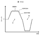
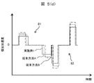
- FIG. 5 is an explanatory diagram for explaining the curvature and the behavior of the vehicle when traveling on the traveling route of the first example described in the first embodiment.
- FIG. 5 shows the curvature and the behavior of the vehicle 60 while traveling on the curve shown in FIG. 4 at a constant speed.
- FIG. 5 (a) shows the change in curvature with respect to the passage of time
- FIG. 5 (b) shows the change in yaw rate with the passage of time
- FIG. 5 (c) shows the lateral acceleration with respect to the passage of time
- FIG. 5 (d) shows the change with respect to the passage of time.
- the lateral acceleration is shown
- the broken line shows the conventional method A
- the alternate long and short dash line shows the conventional method B
- the solid line shows Example 1.
- the peak curvature when the vehicle 60 travels on the first curve 81 in the first embodiment is determined by the conventional method A or the conventional method B. Is larger than the peak curvature when the vehicle 60 travels on the first curve 81 (the peak curvature of the first curve of the conventional method).
- the yaw rate and the lateral acceleration are larger than those of the conventional method A and the conventional method B.
- the first embodiment By making the peak curvature of the first curve 81 of the first embodiment larger than the peak curvature of the first curve 81 of the conventional method, the first embodiment can be generated more than the conventional method A and the conventional method B. The degree of freedom of the travel route that can be created is increased.
- the peak curvature when the vehicle 60 travels on the second curve 82 in the first embodiment (the peak curvature of the second curve 82 in the first embodiment) is set, and the vehicle 60 is the second curve in the conventional method A and the conventional method B. It can be made smaller than the peak curvature when traveling on 82 (the peak curvature of the second curve 82 of the conventional method).
- the first embodiment has a higher yaw rate and lateral acceleration than the conventional method A and the conventional method B. , The absolute value of lateral acceleration can be reduced.
- the decrease in the yaw rate and the lateral acceleration in the second curve 82 is made larger than the increase in the yaw rate and the lateral acceleration in the first curve 81. Can be done.
- the absolute value of the lateral acceleration near the inflection point of the curvature between the first curve 81 and the second curve 82 can be reduced.
- the behavior of the vehicle can be reduced, and the riding comfort can be improved as compared with the conventional method A and the conventional method B.
- FIG. 6 is an explanatory diagram for explaining the traveling route of the second example described in the first embodiment.
- FIG. 6 shows a curve in which a vehicle 60 equipped with an in-vehicle system 1 having a vehicle motion control device 2 is composed of a first curve 83 and a second curve 84 having a peak curvature larger than that of the first curve 83 (peak curvature is in the middle). It is a traveling path existing in the travelable area 70 when traveling at a constant speed on a curve (a curve that changes with and has the same turning direction).
- FIG. 6 shows a route for the vehicle 60 to travel in the travelable area 70
- the broken line is the route of the conventional method A traveling in the center of the travelable area 70
- the alternate long and short dash line is the peak curvature of the first curve 83.
- the peak curvature of the second curve 84 is smaller than the peak curvature of the road shape
- the solid line is the traveling route when the first embodiment is used.
- the peak curvature of the traveling path when traveling on the first curve 83 is set to a curvature larger than the peak curvature of the road shape, and the traveling path when traveling on the second curve 84. Set the peak curvature to a curvature smaller than the peak curvature of the road shape.
- FIG. 7 is an explanatory diagram for explaining the curvature and the behavior of the vehicle when traveling on the traveling path of the second example described in the first embodiment.
- FIG. 7 shows the curvature and the behavior of the vehicle 60 while traveling on the curve shown in FIG. 6 at a constant speed.
- FIG. 7 (a) shows the change in curvature with respect to the passage of time
- FIG. 7 (b) shows the change in yaw rate with the passage of time
- FIG. 7 (c) shows the lateral acceleration with respect to the passage of time
- FIG. 7 (d) shows the change with respect to the passage of time.
- the lateral acceleration is shown
- the broken line shows the conventional method A
- the alternate long and short dash line shows the conventional method B
- the solid line shows Example 1.
- the peak curvature of the traveling path when traveling on the first curve 83 having the smaller peak curvature with respect to the curve in which the peak curvature changes in the middle and the turning direction is the same. Is made larger than the peak curvature of the road shape, and the peak curvature of the traveling path when traveling on the second curve 84 having the larger peak curvature is made smaller than the peak curvature of the road shape. Then, the peak curvature of the first curve 83 and the peak curvature of the second curve 84 are set to the same value and aggregated into one curve having one peak curvature.
- the peak curvature when the vehicle 60 travels on a curve in the first embodiment is conventionally set.
- the peak curvature when the vehicle 60 travels on a curve can be made smaller.
- the absolute value of the lateral acceleration can be made smaller than that of the conventional method A and the conventional method B.
- the lateral acceleration generated between the first curve 83 and the second curve 84 can be set to zero.
- the absolute value of the lateral acceleration near the inflection point of the curvature between the first curve 81 and the second curve 82 can be reduced (to zero).
- the behavior of the vehicle can be reduced, and the riding comfort can be improved as compared with the conventional method A and the conventional method B.
- the peak curvature of the first curve small: 1/50
- the peak curvature of the second curve large: 1/40
- the setting of the peak curvature will be described.
- the peak curvature of the traveling path when traveling on the first curve is 1/47
- the peak curvature of the traveling path when traveling on the second curve is 1/42.
- the change in curvature of the generated traveling path is linear, and the change in curvature of the generated traveling path may be non-linear such as a sine half-wavelength diminishing curve or a cubic curve.
- the peak of the curvature in the entire traveling path is reduced, and the behavior of the vehicle is small. Can be realized.
- FIG. 8 is an explanatory diagram illustrating a functional block of the traveling track generation unit 22 described in the second embodiment.
- the route planning unit 22d is changed to the route candidate planning unit 22h and the trajectory selecting unit 22i is added as compared with the traveling track generating unit 22 described in the first embodiment. The point is different.
- the route candidate planning unit 22h has travel status information output from the information acquisition unit 22a, the number (information) of curves existing in the traveling direction of the vehicle output from the road determination unit 22b, and the length of each detected curve. , Width, curvature (peak curvature), turning direction, start point, end point, and other curve information, and the determination result (information) of whether or not the travel path output from the route determination unit 22f is within the travelable area is input. , Generates a plurality of travel paths existing in the travelable area.
- the plurality of travel routes generated by the route candidate planning unit 22h may have different peak curvatures, as well as different lengths of each section and coordinates of the start point of the first curve.
- the speed planning unit 22g inputs a plurality of traveling routes output from the traveling status information and the route candidate planning unit 22h, sets the speed (traveling speed) at each point existing on the plurality of traveling routes, and sets a plurality of traveling speeds. It is output to the orbit selection unit 22i as an orbit.
- the track selection unit 22i inputs a plurality of travel tracks output from the travel status information and the speed planning unit 22g, selects one travel track as a vehicle travel target, and outputs the travel track to the travel control unit 23 as the travel track. do.
- the track selection unit 22i selects a travel track that matches the travel mode.
- the traveling mode includes a shortest time mode and a shortest distance mode. For example, when setting the shortest time mode, the traveling track having the shortest traveling time is selected from a plurality of traveling tracks, and the shortest distance mode is selected. When setting, the traveling track having the shortest moving distance is selected from a plurality of traveling tracks.
- the track selection unit 22i sets a plurality of traveling tracks, selects the traveling track having the shortest traveling time from the plurality of traveling tracks, and selects the traveling track having the shortest traveling distance from the plurality of traveling tracks.
- the peak of the curvature in the entire traveling path is reduced, and a comfortable ride with less vehicle behavior is realized. Can be done.
- the second embodiment there is a restriction on the distance between the curves, and even when traveling on a continuous curve in which the curvature of the curve changes in the middle, the behavior of the vehicle while traveling on the curve is It is possible to generate a driving route that realizes a small and comfortable ride.
- the present invention is not limited to the above-described embodiment, and includes various modifications.
- the above-described embodiment has been specifically described in order to explain the present invention in an easy-to-understand manner, and is not necessarily limited to those having all the described configurations.
Landscapes
- Engineering & Computer Science (AREA)
- Automation & Control Theory (AREA)
- Transportation (AREA)
- Mechanical Engineering (AREA)
- Human Computer Interaction (AREA)
- Physics & Mathematics (AREA)
- Mathematical Physics (AREA)
- Control Of Driving Devices And Active Controlling Of Vehicle (AREA)
Abstract
La présente invention concerne un dispositif de commande de mouvement de véhicule au moyen duquel le comportement d'un véhicule lors d'un déplacement sur un virage est réduit et au moyen duquel un itinéraire de déplacement permettant un déplacement confortable est généré, y compris lors d'un déplacement sur un virage continu avec une distance limitée entre les virages. Ce dispositif de commande de mouvement de véhicule est caractérisé en ce qu'il comprend une unité de génération de trajectoire de déplacement qui, sur la base d'informations relatives aux courbures d'un premier virage d'une voie présente dans la direction d'avancée du véhicule et d'un second virage relié au premier virage, définit la courbure de l'itinéraire de déplacement lorsque le véhicule se déplace sur le virage de moindre courbure parmi le premier virage et le second virage de sorte à être supérieure à la courbure du virage, définit la courbure de l'itinéraire de déplacement lorsque le véhicule se déplace sur le virage de plus grande courbure de sorte à être inférieure à la courbure du virage, et génère un itinéraire de déplacement.
Priority Applications (3)
| Application Number | Priority Date | Filing Date | Title |
|---|---|---|---|
| CN202180026503.4A CN115379975B (zh) | 2020-04-14 | 2021-04-12 | 车辆运动控制装置及车辆运动控制方法 |
| EP21789357.7A EP4137377B1 (fr) | 2020-04-14 | 2021-04-12 | Dispositif de commande de mouvement de véhicule et procédé de commande de mouvement de véhicule |
| US17/918,019 US12103555B2 (en) | 2020-04-14 | 2021-04-12 | Vehicle motion control device and vehicle motion control method |
Applications Claiming Priority (2)
| Application Number | Priority Date | Filing Date | Title |
|---|---|---|---|
| JP2020-072161 | 2020-04-14 | ||
| JP2020072161A JP7341941B2 (ja) | 2020-04-14 | 2020-04-14 | 車両運動制御装置及び車両運転制御方法 |
Publications (1)
| Publication Number | Publication Date |
|---|---|
| WO2021210519A1 true WO2021210519A1 (fr) | 2021-10-21 |
Family
ID=78085309
Family Applications (1)
| Application Number | Title | Priority Date | Filing Date |
|---|---|---|---|
| PCT/JP2021/015109 Ceased WO2021210519A1 (fr) | 2020-04-14 | 2021-04-12 | Dispositif de commande de mouvement de véhicule et procédé de commande de mouvement de véhicule |
Country Status (5)
| Country | Link |
|---|---|
| US (1) | US12103555B2 (fr) |
| EP (1) | EP4137377B1 (fr) |
| JP (1) | JP7341941B2 (fr) |
| CN (1) | CN115379975B (fr) |
| WO (1) | WO2021210519A1 (fr) |
Cited By (1)
| Publication number | Priority date | Publication date | Assignee | Title |
|---|---|---|---|---|
| CN114509086A (zh) * | 2022-02-15 | 2022-05-17 | 湖南大学无锡智能控制研究院 | 智能车辆在连续弯道场景下的最优轨迹规划方法及系统 |
Families Citing this family (3)
| Publication number | Priority date | Publication date | Assignee | Title |
|---|---|---|---|---|
| JP7687869B2 (ja) * | 2021-05-31 | 2025-06-03 | Astemo株式会社 | 車両統合制御装置及び車両統合制御方法 |
| JP7800348B2 (ja) * | 2022-08-30 | 2026-01-16 | 株式会社アイシン | 運転支援装置及びコンピュータプログラム |
| CN119590452A (zh) * | 2024-12-04 | 2025-03-11 | 奇瑞智能汽车科技(合肥)有限公司 | 车辆的弯道速度控制方法、装置、车辆及存储介质 |
Citations (4)
| Publication number | Priority date | Publication date | Assignee | Title |
|---|---|---|---|---|
| JP2011207242A (ja) * | 2010-03-26 | 2011-10-20 | Toyota Motor Corp | 車両走行制御システム |
| JP2017100652A (ja) | 2015-12-04 | 2017-06-08 | 株式会社デンソー | 走行軌跡生成装置、走行軌跡生成方法 |
| JP2017146215A (ja) * | 2016-02-18 | 2017-08-24 | デジスパイス株式会社 | ラップ予想タイム表示装置 |
| JP2017149184A (ja) * | 2016-02-22 | 2017-08-31 | 本田技研工業株式会社 | 操舵アシスト装置及び操舵アシスト回路 |
Family Cites Families (14)
| Publication number | Priority date | Publication date | Assignee | Title |
|---|---|---|---|---|
| FR2875022B1 (fr) * | 2004-09-07 | 2006-11-24 | Renault V I Sa | Procede de determination en temps reel de la trajectoire cible d'un vehicule |
| JP4967806B2 (ja) * | 2007-05-22 | 2012-07-04 | 株式会社日立製作所 | 経路曲率に応じた車両の速度制御装置 |
| JP5601224B2 (ja) * | 2010-03-04 | 2014-10-08 | 株式会社デンソー | 道路形状学習装置 |
| WO2012137355A1 (fr) * | 2011-04-08 | 2012-10-11 | トヨタ自動車株式会社 | Système d'aide à la conduite |
| JP5417386B2 (ja) * | 2011-07-01 | 2014-02-12 | 日立オートモティブシステムズ株式会社 | 車両運動制御装置 |
| JP5890736B2 (ja) * | 2012-04-13 | 2016-03-22 | 本田技研工業株式会社 | 走行支援制御装置 |
| JP2013248925A (ja) * | 2012-05-30 | 2013-12-12 | Hitachi Automotive Systems Ltd | 車両制御装置 |
| US9821801B2 (en) * | 2015-06-29 | 2017-11-21 | Mitsubishi Electric Research Laboratories, Inc. | System and method for controlling semi-autonomous vehicles |
| JP6731234B2 (ja) * | 2015-10-30 | 2020-07-29 | 日立オートモティブシステムズ株式会社 | 車両運動制御装置及びその方法 |
| JP6654121B2 (ja) * | 2016-09-23 | 2020-02-26 | 日立オートモティブシステムズ株式会社 | 車両運動制御装置 |
| JP6637400B2 (ja) * | 2016-10-12 | 2020-01-29 | 本田技研工業株式会社 | 車両制御装置 |
| JP6528336B2 (ja) * | 2017-06-02 | 2019-06-12 | 本田技研工業株式会社 | 車両制御システムおよび車両制御方法 |
| US10754341B2 (en) * | 2018-02-07 | 2020-08-25 | Baidu Usa Llc | Systems and methods for accelerated curve projection |
| JP7230795B2 (ja) * | 2019-12-25 | 2023-03-01 | トヨタ自動車株式会社 | 車両制御装置 |
-
2020
- 2020-04-14 JP JP2020072161A patent/JP7341941B2/ja active Active
-
2021
- 2021-04-12 CN CN202180026503.4A patent/CN115379975B/zh active Active
- 2021-04-12 EP EP21789357.7A patent/EP4137377B1/fr active Active
- 2021-04-12 US US17/918,019 patent/US12103555B2/en active Active
- 2021-04-12 WO PCT/JP2021/015109 patent/WO2021210519A1/fr not_active Ceased
Patent Citations (4)
| Publication number | Priority date | Publication date | Assignee | Title |
|---|---|---|---|---|
| JP2011207242A (ja) * | 2010-03-26 | 2011-10-20 | Toyota Motor Corp | 車両走行制御システム |
| JP2017100652A (ja) | 2015-12-04 | 2017-06-08 | 株式会社デンソー | 走行軌跡生成装置、走行軌跡生成方法 |
| JP2017146215A (ja) * | 2016-02-18 | 2017-08-24 | デジスパイス株式会社 | ラップ予想タイム表示装置 |
| JP2017149184A (ja) * | 2016-02-22 | 2017-08-31 | 本田技研工業株式会社 | 操舵アシスト装置及び操舵アシスト回路 |
Non-Patent Citations (1)
| Title |
|---|
| See also references of EP4137377A4 |
Cited By (2)
| Publication number | Priority date | Publication date | Assignee | Title |
|---|---|---|---|---|
| CN114509086A (zh) * | 2022-02-15 | 2022-05-17 | 湖南大学无锡智能控制研究院 | 智能车辆在连续弯道场景下的最优轨迹规划方法及系统 |
| CN114509086B (zh) * | 2022-02-15 | 2022-11-25 | 湖南大学无锡智能控制研究院 | 智能车辆在连续弯道场景下的最优轨迹规划方法及系统 |
Also Published As
| Publication number | Publication date |
|---|---|
| CN115379975A (zh) | 2022-11-22 |
| JP7341941B2 (ja) | 2023-09-11 |
| JP2021169234A (ja) | 2021-10-28 |
| US12103555B2 (en) | 2024-10-01 |
| EP4137377A1 (fr) | 2023-02-22 |
| CN115379975B (zh) | 2025-07-29 |
| EP4137377A4 (fr) | 2024-04-24 |
| US20230137911A1 (en) | 2023-05-04 |
| EP4137377B1 (fr) | 2025-03-12 |
Similar Documents
| Publication | Publication Date | Title |
|---|---|---|
| US10754341B2 (en) | Systems and methods for accelerated curve projection | |
| WO2021210519A1 (fr) | Dispositif de commande de mouvement de véhicule et procédé de commande de mouvement de véhicule | |
| JP6380274B2 (ja) | 自動運転車両用ナビゲーション装置 | |
| JP6512084B2 (ja) | 走行軌跡生成装置、走行軌跡生成方法 | |
| US11199842B2 (en) | Determining driving paths for autonomous driving using parallel processing | |
| RU2671602C1 (ru) | Устройство формирования целевого маршрута и устройство управления приведением в движение | |
| WO2017094907A1 (fr) | Dispositif de production de trajectoire de déplacement et procédé de production de trajectoire de déplacement | |
| US12434712B2 (en) | Vehicle motion control device and vehicle motion control method | |
| KR20210052633A (ko) | 자율주행차량 및 그의 유턴 경로 생성 방법 | |
| US20200379474A1 (en) | Determining speeds for an autonomous vehicle | |
| CN113928334A (zh) | 用于自主车辆的基于随机位移的路径定心系统 | |
| JP6658968B2 (ja) | 運転支援方法及び運転支援装置 | |
| WO2021256069A1 (fr) | Dispositif de commande de mouvement de véhicule et procédé de commande de mouvement de véhicule | |
| JP2010217988A (ja) | 運転支援装置、運転支援方法および運転支援プログラム | |
| JP7624878B2 (ja) | 車両運動制御装置、および、車両運動制御方法 | |
| EP4538130A1 (fr) | Dispositif de commande de mouvement de véhicule et procédé de commande de mouvement de véhicule | |
| CN112765191B (zh) | Adas数据增量发送方法、系统、电子设备及存储介质 | |
| WO2025028060A1 (fr) | Dispositif de commande de mouvement d'un véhicule | |
| WO2024241872A1 (fr) | Dispositif de commande de fonctionnement de véhicule et procédé de commande de fonctionnement de véhicule |
Legal Events
| Date | Code | Title | Description |
|---|---|---|---|
| 121 | Ep: the epo has been informed by wipo that ep was designated in this application |
Ref document number: 21789357 Country of ref document: EP Kind code of ref document: A1 |
|
| NENP | Non-entry into the national phase |
Ref country code: DE |
|
| ENP | Entry into the national phase |
Ref document number: 2021789357 Country of ref document: EP Effective date: 20221114 |
|
| WWG | Wipo information: grant in national office |
Ref document number: 202180026503.4 Country of ref document: CN |