WO2021210548A1 - Procédé de codage de données tridimensionnelles, procédé de décodage de données tridimensionnelles, dispositif de codage de données tridimensionnelles et dispositif de décodage de données tridimensionnelles - Google Patents
Procédé de codage de données tridimensionnelles, procédé de décodage de données tridimensionnelles, dispositif de codage de données tridimensionnelles et dispositif de décodage de données tridimensionnelles Download PDFInfo
- Publication number
- WO2021210548A1 WO2021210548A1 PCT/JP2021/015213 JP2021015213W WO2021210548A1 WO 2021210548 A1 WO2021210548 A1 WO 2021210548A1 JP 2021015213 W JP2021015213 W JP 2021015213W WO 2021210548 A1 WO2021210548 A1 WO 2021210548A1
- Authority
- WO
- WIPO (PCT)
- Prior art keywords
- coding
- data
- dimensional
- information
- unit
- Prior art date
- Legal status (The legal status is an assumption and is not a legal conclusion. Google has not performed a legal analysis and makes no representation as to the accuracy of the status listed.)
- Ceased
Links
Images




















































Classifications
-
- H—ELECTRICITY
- H04—ELECTRIC COMMUNICATION TECHNIQUE
- H04N—PICTORIAL COMMUNICATION, e.g. TELEVISION
- H04N19/00—Methods or arrangements for coding, decoding, compressing or decompressing digital video signals
- H04N19/42—Methods or arrangements for coding, decoding, compressing or decompressing digital video signals characterised by implementation details or hardware specially adapted for video compression or decompression, e.g. dedicated software implementation
-
- H—ELECTRICITY
- H04—ELECTRIC COMMUNICATION TECHNIQUE
- H04N—PICTORIAL COMMUNICATION, e.g. TELEVISION
- H04N19/00—Methods or arrangements for coding, decoding, compressing or decompressing digital video signals
- H04N19/50—Methods or arrangements for coding, decoding, compressing or decompressing digital video signals using predictive coding
- H04N19/597—Methods or arrangements for coding, decoding, compressing or decompressing digital video signals using predictive coding specially adapted for multi-view video sequence encoding
-
- G—PHYSICS
- G06—COMPUTING OR CALCULATING; COUNTING
- G06T—IMAGE DATA PROCESSING OR GENERATION, IN GENERAL
- G06T17/00—Three-dimensional [3D] modelling for computer graphics
-
- G—PHYSICS
- G06—COMPUTING OR CALCULATING; COUNTING
- G06T—IMAGE DATA PROCESSING OR GENERATION, IN GENERAL
- G06T9/00—Image coding
- G06T9/40—Tree coding, e.g. quadtree, octree
-
- H—ELECTRICITY
- H04—ELECTRIC COMMUNICATION TECHNIQUE
- H04N—PICTORIAL COMMUNICATION, e.g. TELEVISION
- H04N19/00—Methods or arrangements for coding, decoding, compressing or decompressing digital video signals
- H04N19/10—Methods or arrangements for coding, decoding, compressing or decompressing digital video signals using adaptive coding
- H04N19/134—Methods or arrangements for coding, decoding, compressing or decompressing digital video signals using adaptive coding characterised by the element, parameter or criterion affecting or controlling the adaptive coding
- H04N19/136—Incoming video signal characteristics or properties
-
- H—ELECTRICITY
- H04—ELECTRIC COMMUNICATION TECHNIQUE
- H04N—PICTORIAL COMMUNICATION, e.g. TELEVISION
- H04N19/00—Methods or arrangements for coding, decoding, compressing or decompressing digital video signals
- H04N19/70—Methods or arrangements for coding, decoding, compressing or decompressing digital video signals characterised by syntax aspects related to video coding, e.g. related to compression standards
Definitions
- the present disclosure relates to a three-dimensional data coding method, a three-dimensional data decoding method, a three-dimensional data coding device, and a three-dimensional data decoding device.
- 3D data In the future, devices or services that utilize 3D data are expected to become widespread in a wide range of fields such as computer vision for autonomous operation of automobiles or robots, map information, monitoring, infrastructure inspection, or video distribution.
- the three-dimensional data is acquired by various methods such as a distance sensor such as a range finder, a stereo camera, or a combination of a plurality of monocular cameras.
- a point cloud that expresses the shape of a three-dimensional structure by a point cloud in a three-dimensional space.
- the position and color of the point cloud are stored.
- Point clouds are expected to become the mainstream method for expressing three-dimensional data, but point clouds have a very large amount of data. Therefore, in the storage or transmission of 3D data, it is essential to compress the amount of data by coding, as in the case of 2D moving images (for example, MPEG-4 AVC or HEVC standardized by MPEG). Become.
- point cloud compression is partially supported by a public library (Point Cloud Library) that performs point cloud-related processing.
- Point Cloud Library a public library that performs point cloud-related processing.
- Patent Document 1 a technique for searching and displaying facilities located around a vehicle using three-dimensional map data is known (see, for example, Patent Document 1).
- An object of the present disclosure is to provide a three-dimensional data coding method, a three-dimensional data decoding method, a three-dimensional data coding device, or a three-dimensional data decoding device that can improve the coding efficiency.
- the three-dimensional data coding method acquires a first data unit including a plurality of first three-dimensional points, and the plurality of first three-dimensional points included in the acquired first data unit. Is encoded by one of a plurality of coding methods having different methods, and a bit stream including the first coded data in which the plurality of first three-dimensional points are encoded and the first identification information is generated. In coding, it is determined whether or not to encode by continuously using the context used for coding, and among the plurality of coding methods, the above-mentioned context used in the coding method used for the coding is described. The plurality of first three-dimensional points are encoded using a context according to the decision result in the decision, and the first identification information indicates the decision result in the decision.
- the three-dimensional data decoding method indicates whether or not to continuously use the first encoded data in which a plurality of first three-dimensional points are encoded and the context used for encoding.
- the first encoded data is decoded using the context corresponding to the first identification information.
- the present disclosure can provide a three-dimensional data coding method, a three-dimensional data decoding method, a three-dimensional data coding device, or a three-dimensional data decoding device that can improve the coding efficiency.
- FIG. 1 is a diagram showing a configuration of a three-dimensional data coding / decoding system according to the first embodiment.
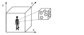
- FIG. 2 is a diagram showing a configuration example of point cloud data according to the first embodiment.
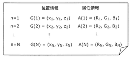
- FIG. 3 is a diagram showing a configuration example of a data file in which the point cloud data information according to the first embodiment is described.
- FIG. 4 is a diagram showing the types of point cloud data according to the first embodiment.
- FIG. 5 is a diagram showing a configuration of a first coding unit according to the first embodiment.
- FIG. 6 is a block diagram of the first coding unit according to the first embodiment.
- FIG. 7 is a diagram showing a configuration of a first decoding unit according to the first embodiment.
- FIG. 1 is a diagram showing a configuration of a three-dimensional data coding / decoding system according to the first embodiment.
- FIG. 2 is a diagram showing a configuration example of point cloud data according to the first embodiment.
- FIG. 3 is a diagram showing a
- FIG. 8 is a block diagram of the first decoding unit according to the first embodiment.
- FIG. 9 is a block diagram of the three-dimensional data coding device according to the first embodiment.
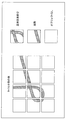
- FIG. 10 is a diagram showing an example of position information according to the first embodiment.
- FIG. 11 is a diagram showing an example of an ocree representation of position information according to the first embodiment.
- FIG. 12 is a block diagram of the three-dimensional data decoding device according to the first embodiment.
- FIG. 13 is a block diagram of the attribute information coding unit according to the first embodiment.
- FIG. 14 is a block diagram of the attribute information decoding unit according to the first embodiment.
- FIG. 15 is a block diagram showing a configuration of an attribute information coding unit according to the first embodiment.
- FIG. 16 is a block diagram of the attribute information coding unit according to the first embodiment.
- FIG. 17 is a block diagram showing a configuration of an attribute information decoding unit according to the first embodiment.
- FIG. 18 is a block diagram of the attribute information decoding unit according to the first embodiment.
- FIG. 19 is a diagram showing a configuration of a second coding unit according to the first embodiment.
- FIG. 20 is a block diagram of a second coding unit according to the first embodiment.
- FIG. 21 is a diagram showing a configuration of a second decoding unit according to the first embodiment.
- FIG. 22 is a block diagram of a second decoding unit according to the first embodiment.
- FIG. 23 is a diagram showing a protocol stack related to PCC coded data according to the first embodiment.
- FIG. 24 is a diagram showing a configuration of a coding unit and a multiplexing unit according to the second embodiment.
- FIG. 25 is a diagram showing a configuration example of coded data according to the second embodiment.
- FIG. 26 is a diagram showing a configuration example of the coded data and the NAL unit according to the second embodiment.
- FIG. 27 is a diagram showing an example of semantics of pcc_nal_unit_type according to the second embodiment.
- FIG. 28 is a diagram showing an example of the delivery order of the NAL unit according to the second embodiment.
- FIG. 29 is a flowchart of processing by the three-dimensional data coding apparatus according to the second embodiment.
- FIG. 30 is a flowchart of processing by the three-dimensional data decoding device according to the second embodiment.
- FIG. 31 is a flowchart of the multiplexing process according to the second embodiment.
- FIG. 32 is a flowchart of the demultiplexing process according to the second embodiment.
- FIG. 33 is a block diagram of the first coding unit according to the third embodiment.
- FIG. 34 is a block diagram of the first decoding unit according to the third embodiment.
- FIG. 35 is a block diagram of the divided portion according to the third embodiment.
- FIG. 36 is a diagram showing a division example of slices and tiles according to the third embodiment.
- FIG. 37 is a diagram showing an example of a slice and tile division pattern according to the third embodiment.
- FIG. 38 is a diagram showing an example of the dependency relationship according to the third embodiment.
- FIG. 39 is a diagram showing an example of the decoding order of the data according to the third embodiment.
- FIG. 40 is a flowchart of the coding process according to the third embodiment.
- FIG. 41 is a block diagram of the joint portion according to the third embodiment.
- FIG. 42 is a diagram showing a configuration example of the coded data and the NAL unit according to the third embodiment.
- FIG. 43 is a flowchart of the coding process according to the third embodiment.
- FIG. 44 is a flowchart of the decoding process according to the third embodiment.
- FIG. 45 is a flowchart of the coding process according to the third embodiment.
- FIG. 46 is a flowchart of the decoding process according to the third embodiment.
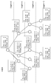
- FIG. 47 is a diagram showing an example of a prediction tree used in the three-dimensional data coding method according to the fourth embodiment.
- FIG. 41 is a block diagram of the joint portion according to the third embodiment.
- FIG. 42 is a diagram showing a configuration example of the coded data and the NAL unit according to the third embodiment.
- FIG. 43 is a flowchart of the
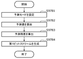
- FIG. 48 is a flowchart showing an example of the three-dimensional data coding method according to the fourth embodiment.
- FIG. 49 is a flowchart showing an example of the three-dimensional data decoding method according to the fourth embodiment.
- FIG. 50 is a diagram for explaining a method of generating a predicted tree according to the fourth embodiment.
- FIG. 51 is a diagram for explaining a first example of the prediction mode according to the fourth embodiment.
- FIG. 52 is a diagram showing a second example of a table showing predicted values calculated in each prediction mode according to the fourth embodiment.
- FIG. 53 is a diagram showing a specific example of the second example of the table showing the predicted values calculated in each prediction mode according to the fourth embodiment.
- FIG. 54 is a diagram showing a third example of a table showing predicted values calculated in each prediction mode according to the fourth embodiment.
- FIG. 55 is a diagram showing a fourth example of a table showing predicted values calculated in each prediction mode according to the fourth embodiment.
- FIG. 56 is a diagram showing a fifth example of a table showing predicted values calculated in each prediction mode according to the fourth embodiment.
- FIG. 57 is a diagram showing a sixth example of a table showing predicted values calculated in each prediction mode according to the fourth embodiment.
- FIG. 58 is a diagram showing a seventh example of a table showing predicted values calculated in each prediction mode according to the fourth embodiment.
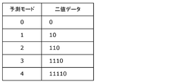
- FIG. 59 is a diagram showing a first example of a binarization table in the case where the prediction mode value according to the fourth embodiment is binarized and encoded.
- FIG. 60 is a diagram showing a second example of a binarization table in the case where the prediction mode value according to the fourth embodiment is binarized and encoded.
- FIG. 61 is a diagram showing a third example of a binarization table in the case where the prediction mode value according to the fourth embodiment is binarized and encoded.
- FIG. 62 is a diagram for explaining an example of encoding the binary data of the binarization table when the prediction mode according to the fourth embodiment is binarized and encoded.
- FIG. 63 is a flowchart showing an example of coding of the prediction mode value according to the fourth embodiment.
- FIG. 64 is a flowchart showing an example of decoding the predicted mode value according to the fourth embodiment.
- FIG. 65 is a diagram showing another example of a table showing predicted values calculated in each prediction mode according to the fourth embodiment.
- FIG. 66 is a diagram for explaining an example of encoding the binary data of the binarization table when the prediction mode according to the fourth embodiment is binarized and encoded.
- FIG. 67 is a flowchart showing another example of coding the prediction mode value according to the fourth embodiment.
- FIG. 68 is a flowchart showing another example of decoding the predicted mode value according to the fourth embodiment.
- FIG. 69 is a flowchart showing an example of a process of determining whether or not to fix the prediction mode value according to the condition A at the time of coding according to the fourth embodiment.
- FIG. 70 is a flowchart showing an example of a process of determining whether to set the prediction mode value to a fixed value or to decode according to the condition A at the time of decoding according to the fourth embodiment.
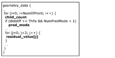
- FIG. 71 is a diagram showing an example of the syntax of the header of the position information according to the fourth embodiment.
- FIG. 72 is a diagram showing an example of the position information syntax according to the fourth embodiment.
- FIG. 73 is a diagram showing another example of the position information syntax according to the fourth embodiment.
- FIG. 74 is a diagram showing an example of a prediction tree used in the three-dimensional data coding method according to the fifth embodiment.
- FIG. 75 is a diagram showing another example of the position information syntax according to the fifth embodiment.
- FIG. 71 is a diagram showing an example of the syntax of the header of the position information according to the fourth embodiment.
- FIG. 72 is a diagram showing an example of the position information syntax according to the fourth embodiment.
- FIG. 73 is a diagram showing another example of the position information
- FIG. 76 is a diagram showing an example of the configuration of the prediction tree commonly used for coding the position information and the attribute information according to the fifth embodiment.
- FIG. 77 is a flowchart showing an example of a three-dimensional data coding method according to a modified example of the fifth embodiment.
- FIG. 78 is a flowchart showing an example of a three-dimensional data decoding method according to a modified example of the fifth embodiment.
- FIG. 79 is a diagram showing an example of the syntax of the header of the attribute information according to the fifth embodiment.
- FIG. 80 is a diagram showing another example of the syntax of the attribute information according to the fifth embodiment.
- FIG. 81 is a diagram showing an example of the syntax of position information and attribute information according to the fifth embodiment.
- FIG. 82 is a flowchart of processing of the three-dimensional data coding apparatus according to the fourth and fifth embodiments.
- FIG. 83 is a flowchart of processing of the three-dimensional data decoding apparatus according to the fourth and fifth embodiments.
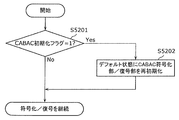
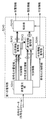
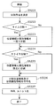
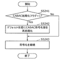
- FIG. 84 is a flowchart showing a process of reinitializing the CABAC coding / decoding engine according to the CABAC initialization flag at the time of coding or decoding according to the sixth embodiment.
- FIG. 85 is a block diagram showing a configuration of a first coding unit included in the three-dimensional data coding device according to the sixth embodiment.
- FIG. 86 is a block diagram showing the configuration of the divided portion according to the sixth embodiment.
- FIG. 87 is a block diagram showing a configuration of a position information coding unit and an attribute information coding unit according to the sixth embodiment.
- FIG. 88 is a block diagram showing the configuration of the first decoding unit according to the sixth embodiment.
- FIG. 89 is a block diagram showing a configuration of a position information decoding unit and an attribute information decoding unit according to the sixth embodiment.
- FIG. 90 is a flowchart showing an example of processing related to initialization of CABAC in coding of position information or coding of attribute information according to the sixth embodiment.
- FIG. 91 is a diagram showing an example of the timing of CABAC initialization in the point cloud data as a bit stream according to the sixth embodiment.
- FIG. 92 is a diagram showing the configuration of the coded data according to the sixth embodiment and the method of storing the coded data in the NAL unit.
- FIG. 93 is a flowchart showing an example of the process related to the initialization of the CABAC in the decoding of the position information or the decoding of the attribute information according to the sixth embodiment.
- FIG. 94 is a flowchart of the point cloud data coding process according to the sixth embodiment.
- FIG. 95 is a flowchart showing an example of the process of updating the additional information according to the sixth embodiment.
- FIG. 96 is a flowchart showing an example of the CABAC initialization process according to the sixth embodiment.
- FIG. 97 is a flowchart of the point cloud data decoding process according to the sixth embodiment.
- FIG. 98 is a flowchart showing an example of the process of initializing the CABAC decoding unit according to the sixth embodiment.
- FIG. 99 is a diagram showing an example of tiles and slices according to the sixth embodiment.
- FIG. 100 is a flowchart showing an example of a method of initializing the CABAC and determining the initial context value according to the sixth embodiment.
- FIG. 101 is a diagram showing an example in which a map in which the point cloud data obtained by LiDAR according to the sixth embodiment is viewed from above is divided into tiles.
- FIG. 102 is a flowchart showing another example of the method of initializing the CABAC and determining the initial value of the context according to the sixth embodiment.
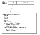
- FIG. 103 is a diagram showing an example of the data structure of the position information included in each of the divided data units according to the seventh embodiment and the syntax of the header of the position information.
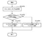
- FIG. 104 is a flowchart showing an example of the three-dimensional data coding method according to the seventh embodiment.
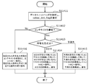
- FIG. 105 is a flowchart showing an example of the three-dimensional data decoding method according to the seventh embodiment.
- FIG. 106 is a diagram for explaining initialization of the context when the coding method according to the seventh embodiment is switched.
- FIG. 107 is a flowchart of processing of the three-dimensional data coding apparatus according to the seventh embodiment.
- FIG. 108 is a flowchart of processing of the three-dimensional data decoding apparatus according to the seventh embodiment.
- FIG. 109 is a diagram showing an example of a three-dimensional point cloud in the case where slices are divided and coded for each group according to the eighth embodiment.
- FIG. 110 is a diagram showing examples of various configurations of the bitstream according to the eighth embodiment.
- FIG. 111 is an example in which a slice flag indicates whether or not to initialize the CABAC in slice units according to the eighth embodiment, and a tree flag indicates whether or not to initialize the CABAC in tree units in the slice.
- FIG. 112 is a diagram for explaining a method of decoding a plurality of prediction trees according to the eighth embodiment by parallel processing.
- FIG. 113 is a diagram showing an example of the three-dimensional data coding method according to the eighth embodiment.
- FIG. 114 is a diagram showing an example of the three-dimensional data decoding method according to the eighth embodiment.
- FIG. 115 is a diagram showing an example of a case of parallel decoding in the three-dimensional data decoding method according to the eighth embodiment.
- FIG. 116 is a diagram showing an example of the syntax of the position information data unit when the initialization flag is stored in the position information data according to the eighth embodiment.
- FIG. 117 is a diagram showing an example of header syntax when the initialization flag and offset information are stored in the header of the position information according to the eighth embodiment.
- FIG. 118 is a diagram showing an example of the header syntax when the initialization flag and the offset information are stored in the header of the position information according to the eighth embodiment in random access units.
- FIG. 119 is a block diagram of the three-dimensional data creation device according to the ninth embodiment.
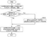
- FIG. 120 is a flowchart of the three-dimensional data creation method according to the ninth embodiment.
- FIG. 121 is a diagram showing a configuration of a system according to a ninth embodiment.
- FIG. 122 is a block diagram of the client device according to the ninth embodiment.
- FIG. 123 is a block diagram of the server according to the ninth embodiment.
- FIG. 124 is a flowchart of the three-dimensional data creation process by the client device according to the ninth embodiment.
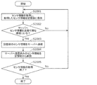
- FIG. 125 is a flowchart of the sensor information transmission process by the client device according to the ninth embodiment.
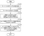
- FIG. 126 is a flowchart of the three-dimensional data creation process by the server according to the ninth embodiment.
- FIG. 127 is a flowchart of a three-dimensional map transmission process by the server according to the ninth embodiment.
- FIG. 128 is a diagram showing a configuration of a modified example of the system according to the ninth embodiment.
- FIG. 129 is a diagram showing a configuration of a server and a client device according to the ninth embodiment.
- FIG. 130 is a diagram showing a configuration of a server and a client device according to the ninth embodiment.
- FIG. 131 is a flowchart of processing by the client device according to the ninth embodiment.
- FIG. 132 is a diagram showing a configuration of a sensor information collecting system according to a ninth embodiment.
- FIG. 133 is a diagram showing an example of the system according to the ninth embodiment.
- FIG. 134 is a diagram showing a modified example of the system according to the ninth embodiment.
- FIG. 135 is a flowchart showing an example of application processing according to the ninth embodiment.
- FIG. 136 is a diagram showing sensor ranges of various sensors according to the ninth embodiment.
- FIG. 137 is a diagram showing a configuration example of the automatic driving system according to the ninth embodiment.
- FIG. 138 is a diagram showing a configuration example of a bit stream according to the ninth embodiment.
- FIG. 139 is a flowchart of the point group selection process according to the ninth embodiment.
- FIG. 140 is a diagram showing a screen example of the point group selection process according to the ninth embodiment.
- FIG. 141 is a diagram showing a screen example of the point group selection process according to the ninth embodiment.
- FIG. 142 is a diagram showing a screen example of the point group selection process according to the ninth embodiment.
- the three-dimensional data coding method acquires a first data unit including a plurality of first three-dimensional points, and the plurality of first three-dimensional points included in the acquired first data unit. Is encoded by one of a plurality of coding methods having different methods, and a bit stream including the first coded data in which the plurality of first three-dimensional points are encoded and the first identification information is generated. In coding, it is determined whether or not to encode by continuously using the context used for coding, and among the plurality of coding methods, the above-mentioned context used in the coding method used for the coding is described. The plurality of first three-dimensional points are encoded using a context according to the decision result in the decision, and the first identification information indicates the decision result in the decision.
- the coding efficiency can be improved, and in order to generate a bit stream containing the first identification information, three-dimensional data decoding is performed. It can be properly decoded by the device.
- the coding method of the plurality of first three-dimensional points among the plurality of coding methods is used. It may be indicated that the plurality of first three-dimensional points are encoded by continuously using the used context, and the first identification information is encoded by continuously using the context used for encoding. good.
- the coding method of the plurality of first three-dimensional points among the plurality of coding methods when it is decided not to continuously use the context used for the coding, in the coding, the coding method of the plurality of first three-dimensional points among the plurality of coding methods.
- the plurality of first three-dimensional points may be encoded by using the initialized context for, and the first identification information may indicate that the context used for encoding is not continuously used.
- each of the plurality of first three-dimensional points includes position information of each first three-dimensional point and attribute information of each first three-dimensional point
- the plurality of coding methods are position information coding methods.
- the attribute information of the plurality of first three-dimensional points is encoded by another coding method, and in the coding, the context used for the coding in the coding is continuously used.
- the positions of the plurality of first three-dimensional points by continuously using the context used in the plurality of first three-dimensional point coding methods among the plurality of coding methods.
- the information may be encoded and (ii) the attribute information of the plurality of first three-dimensional points may be encoded by continuously using the context used in the other coding method.
- the codes of the plurality of first three-dimensional points among the plurality of coding methods when it is decided not to continuously use the context used for the coding in the coding, (i) the codes of the plurality of first three-dimensional points among the plurality of coding methods.
- the position information of the plurality of first three-dimensional points is encoded using the initialized context for the conversion method, and (ii) the plurality of first three-dimensional points are encoded using the initialized context for the other coding method.
- the attribute information of the three-dimensional point may be encoded.
- a second data unit including a plurality of second and third dimensional points encoded next to the plurality of first and third dimensional points is further acquired, and in the encoding, the plurality of second data units are acquired.
- the coding method of the three-dimensional points is different from the coding method of the plurality of first three-dimensional points, it is decided not to continue to use the context used for the coding, and among the plurality of coding methods, the above-mentioned
- the plurality of second-three-dimensional points are encoded using the initialized context for the plurality of second-three-dimensional point coding schemes, and in the generation, the plurality of second-three-dimensional points are further encoded.
- the bit stream including the second coded data and the second identification information may be generated, and the second identification information may indicate that the context used for coding is not continuously used.
- the three-dimensional data decoding method indicates whether or not to continuously use the first encoded data in which a plurality of first three-dimensional points are encoded and the context used for encoding.
- the first encoded data is decoded using the context corresponding to the first identification information.
- a plurality of appropriate first three-dimensional points can be calculated by decoding the first encoded data according to the first identification information included in the bit stream.
- the decoding when the first identification information indicates that the context used for coding is continuously used, the context used in the coding method corresponding to the decoding method is continuously used as described above.
- the first coded data may be decoded.
- the decoding when the first identification information indicates that the context used for coding is not continuously used, it was used for coding the first coded data among the plurality of coding methods.
- the first encoded data may be decoded using the initialized context for the encoding scheme.
- the first coded data includes the coded position information of the plurality of first three-dimensional points and the coded attribute information of the plurality of first three-dimensional points, and the plurality of codes.
- the coding method is a coding method for the position information of the plurality of encoded first and third dimensional points, and the coded attribute information of the plurality of first and third dimensional points is obtained by another coding method.
- Attribute information of a plurality of first and third dimensional points may be calculated by continuously using the context used in the method for decoding.
- the decoding when the first identification information indicates that the context used for coding is not continuously used, (i) the plurality of encoded firsts of the plurality of coding methods.
- the position information of the plurality of encoded first three-dimensional points is calculated, and (ii).
- the attribute information of the plurality of first three-dimensional points may be decoded by decoding using the initialized context for the other coding method.
- bit stream further includes second encoded data in which a plurality of second and third dimensional points are encoded, and second identification information indicating whether or not the context used for encoding is continuously used. Including, the plurality of second and third dimensional points are encoded next to the plurality of first and third dimensional points, and the second identification information does not continue to use the context used for encoding. May be shown.
- the three-dimensional data coding apparatus includes a processor and a memory, and the processor uses the memory to provide a first data unit including a plurality of first three-dimensional points.
- the plurality of first three-dimensional points acquired and included in the acquired first data unit were encoded by one of the plurality of coding methods having different methods, and the plurality of first three-dimensional points were encoded.
- a bit stream containing the first coded data and the first identification information is generated, and in the coding, it is determined whether or not to code using the context used for the coding continuously, and the plurality of coding data are determined.
- the contexts used in the coding method used for the coding according to the decision result in the determination are used to encode the plurality of first three-dimensional points, and the first identification information is obtained. Includes the decision result in the decision.
- the coding efficiency can be improved, and in order to generate a bit stream containing the first identification information, three-dimensional data decoding is performed. It can be properly decoded by the device.
- the three-dimensional data decoding device includes a processor and a memory, and the processor uses the memory to encode a plurality of first three-dimensional points.
- a bit stream including the coded data and the first identification information indicating whether or not to continuously use the context used for coding is acquired, and the first coded data is used in a plurality of coding methods having different methods from each other.
- decoding is performed by a decoding method corresponding to the coding method used for coding the first coded data, and in the decoding, the first coded data is used in a context corresponding to the first identification information. Decrypt.
- a plurality of appropriate first three-dimensional points can be calculated by decoding the first encoded data according to the first identification information included in the bit stream.
- a recording medium such as a system, method, integrated circuit, computer program or computer-readable CD-ROM, and the system, method, integrated circuit, computer program. And any combination of recording media may be realized.
- a three-dimensional data coding method and a three-dimensional data coding device for providing a function of transmitting and receiving necessary information according to an application in the coded data of a three-dimensional point cloud, and the code thereof.
- a three-dimensional data decoding method and a three-dimensional data decoding device for decoding the encoded data, a three-dimensional data multiplexing method for multiplexing the encoded data, and a three-dimensional data transmission method for transmitting the encoded data will be described. do.
- a first coding method and a second coding method are being studied as a coding method (coding method) for point group data.
- the method of storing in the format is not defined, and there is a problem that the MUX processing (multiplexing), transmission or storage in the coding unit cannot be performed as it is.
- FIG. 1 is a diagram showing a configuration example of a three-dimensional data coding / decoding system according to the present embodiment.
- the three-dimensional data coding / decoding system includes a three-dimensional data coding system 4601, a three-dimensional data decoding system 4602, a sensor terminal 4603, and an external connection unit 4604.
- the three-dimensional data coding system 4601 generates coded data or multiplexed data by encoding point cloud data which is three-dimensional data.
- the three-dimensional data coding system 4601 may be a three-dimensional data coding device realized by a single device, or may be a system realized by a plurality of devices. Further, the three-dimensional data coding apparatus may include a part of a plurality of processing units included in the three-dimensional data coding system 4601.
- the three-dimensional data coding system 4601 includes a point cloud data generation system 4611, a presentation unit 4612, a coding unit 4613, a multiplexing unit 4614, an input / output unit 4615, and a control unit 4616.
- the point cloud data generation system 4611 includes a sensor information acquisition unit 4617 and a point cloud data generation unit 4618.
- the sensor information acquisition unit 4617 acquires the sensor information from the sensor terminal 4603 and outputs the sensor information to the point cloud data generation unit 4618.
- the point cloud data generation unit 4618 generates point cloud data from the sensor information and outputs the point cloud data to the coding unit 4613.
- the presentation unit 4612 presents the sensor information or the point cloud data to the user. For example, the presentation unit 4612 displays information or an image based on sensor information or point cloud data.
- the coding unit 4613 encodes (compresses) the point cloud data, and outputs the obtained coded data, the control information obtained in the coding process, and other additional information to the multiplexing unit 4614.
- the additional information includes, for example, sensor information.
- the multiplexing unit 4614 generates multiplexed data by multiplexing the coded data input from the coding unit 4613, the control information, and the additional information.
- the format of the multiplexed data is, for example, a file format for storage or a packet format for transmission.
- the input / output unit 4615 (for example, the communication unit or the interface) outputs the multiplexed data to the outside.
- the multiplexed data is stored in a storage unit such as an internal memory.
- the control unit 4616 (or application execution unit) controls each processing unit. That is, the control unit 4616 controls coding, multiplexing, and the like.
- the sensor information may be input to the coding unit 4613 or the multiplexing unit 4614. Further, the input / output unit 4615 may output the point cloud data or the coded data as it is to the outside.
- the transmission signal (multiplexed data) output from the three-dimensional data coding system 4601 is input to the three-dimensional data decoding system 4602 via the external connection unit 4604.
- the three-dimensional data decoding system 4602 generates point cloud data, which is three-dimensional data, by decoding encoded data or multiplexed data.
- the three-dimensional data decoding system 4602 may be a three-dimensional data decoding device realized by a single device, or may be a system realized by a plurality of devices. Further, the three-dimensional data decoding device may include a part of a plurality of processing units included in the three-dimensional data decoding system 4602.
- the three-dimensional data decoding system 4602 includes a sensor information acquisition unit 4621, an input / output unit 4622, a demultiplexing unit 4623, a decoding unit 4624, a presentation unit 4625, a user interface 4626, and a control unit 4627.
- the sensor information acquisition unit 4621 acquires sensor information from the sensor terminal 4603.
- the input / output unit 4622 acquires the transmission signal, decodes the multiplexed data (file format or packet) from the transmitted signal, and outputs the multiplexed data to the demultiplexed unit 4623.
- the demultiplexing unit 4623 acquires encoded data, control information and additional information from the multiplexing data, and outputs the encoded data, control information and additional information to the decoding unit 4624.
- the decoding unit 4624 reconstructs the point cloud data by decoding the coded data.
- the presentation unit 4625 presents the point cloud data to the user. For example, the presentation unit 4625 displays information or an image based on the point cloud data.
- the user interface 4626 acquires instructions based on user operations.
- the control unit 4627 (or application execution unit) controls each processing unit. That is, the control unit 4627 controls demultiplexing, decoding, presentation, and the like.
- the input / output unit 4622 may acquire the point cloud data or the coded data as it is from the outside. Further, the presentation unit 4625 may acquire additional information such as sensor information and present information based on the additional information. In addition, the presentation unit 4625 may make a presentation based on the user's instruction acquired by the user interface 4626.
- the sensor terminal 4603 generates sensor information, which is information obtained by the sensor.
- the sensor terminal 4603 is a terminal equipped with a sensor or a camera, and includes, for example, a moving object such as an automobile, a flying object such as an airplane, a mobile terminal, or a camera.
- the sensor information that can be acquired by the sensor terminal 4603 is, for example, (1) the distance between the sensor terminal 4603 and the object obtained from the LIDAR, the millimeter-wave radar, or the infrared sensor, or the reflectance of the object, and (2) a plurality.
- the sensor information may include the attitude, orientation, gyro (angular velocity), position (GPS information or altitude), speed, acceleration, and the like of the sensor.
- the sensor information may include temperature, atmospheric pressure, humidity, magnetism, and the like.
- the external connection unit 4604 is realized by communication with an integrated circuit (LSI or IC), an external storage unit, a cloud server via the Internet, broadcasting, or the like.
- LSI integrated circuit
- IC integrated circuit
- cloud server via the Internet, broadcasting, or the like.
- FIG. 2 is a diagram showing a structure of point cloud data.
- FIG. 3 is a diagram showing a configuration example of a data file in which information on point cloud data is described.
- the point cloud data includes data of a plurality of points.
- the data of each point includes position information (three-dimensional coordinates) and attribute information for the position information.
- a collection of multiple points is called a point cloud.
- a point cloud indicates a three-dimensional shape of an object.
- Position information such as three-dimensional coordinates is sometimes called geometry.
- the data of each point may include attribute information (attribute) of a plurality of attribute types.
- the attribute type is, for example, color or reflectance.
- One attribute information may be associated with one position information, or attribute information having a plurality of different attribute types may be associated with one position information. Further, a plurality of attribute information of the same attribute type may be associated with one position information.
- the configuration example of the data file shown in FIG. 3 is an example in which the position information and the attribute information have a one-to-one correspondence, and shows the position information and the attribute information of N points constituting the point cloud data. There is.
- the position information is, for example, information on three axes of x, y, and z.
- the attribute information is, for example, RGB color information.
- a typical data file is a ply file or the like.
- FIG. 4 is a diagram showing the types of point cloud data.
- the point cloud data includes a static object and a dynamic object.
- the static object is 3D point cloud data at an arbitrary time (certain time).
- a dynamic object is three-dimensional point cloud data that changes over time.
- the three-dimensional point cloud data at a certain time is referred to as a PCC frame or a frame.
- the object may be a point cloud whose area is limited to some extent like ordinary video data, or a large-scale point cloud whose area is not limited such as map information.
- the sensor information is acquired by various methods such as a distance sensor such as LIDAR or a range finder, a stereo camera, or a combination of a plurality of monocular cameras.
- the point cloud data generation unit 4618 generates point cloud data based on the sensor information obtained by the sensor information acquisition unit 4617.
- the point cloud data generation unit 4618 generates position information as point cloud data, and adds attribute information for the position information to the position information.
- the point cloud data generation unit 4618 may process the point cloud data when generating the position information or adding the attribute information. For example, the point cloud data generation unit 4618 may reduce the amount of data by deleting the point clouds whose positions overlap. Further, the point cloud data generation unit 4618 may convert the position information (position shift, rotation, normalization, etc.), or may render the attribute information.
- point cloud data generation system 4611 is included in the three-dimensional data coding system 4601 in FIG. 1, it may be provided independently outside the three-dimensional data coding system 4601.
- the coding unit 4613 generates coded data by coding the point cloud data based on a predetermined coding method.
- a predetermined coding method There are roughly the following two types of coding methods.
- the first is a coding method using position information, and this coding method will be hereinafter referred to as a first coding method.
- the second is a coding method using a video codec, and this coding method will be hereinafter referred to as a second coding method.
- the decoding unit 4624 decodes the point cloud data by decoding the coded data based on a predetermined coding method.
- the multiplexing unit 4614 generates multiplexed data by multiplexing the encoded data using an existing multiplexing method.
- the generated multiplexed data is transmitted or accumulated.
- the multiplexing unit 4614 multiplexes other media such as video, audio, subtitles, applications, and files, or reference time information. Further, the multiplexing unit 4614 may further multiplex the attribute information related to the sensor information or the point cloud data.
- the multiplexing method or file format includes ISOBMFF, ISOBMFF-based transmission method MPEG-DASH, MMT, MPEG-2 TS Systems, RMP, and the like.
- the demultiplexing unit 4623 extracts PCC coded data, other media, time information, etc. from the multiplexing data.
- the input / output unit 4615 transmits the multiplexed data by using a method suitable for the medium to be transmitted or the medium to be stored, such as broadcasting or communication.
- the input / output unit 4615 may communicate with other devices via the Internet, or may communicate with a storage unit such as a cloud server.
- http http, ftp, TCP, UDP, etc. are used.
- a PULL type communication method may be used, or a PUSH type communication method may be used.
- Either wired transmission or wireless transmission may be used.
- Ethernet registered trademark
- USB registered trademark
- RS-232C USB-232C
- HDMI registered trademark
- coaxial cable or the like
- wireless transmission a wireless LAN, Wi-Fi (registered trademark), Bluetooth (registered trademark), millimeter wave, or the like is used.
- DVB-T2 DVB-S2, DVB-C2, ATSC3.0, ISDB-S3 or the like is used.
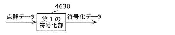
- FIG. 5 is a diagram showing the configuration of the first coding unit 4630, which is an example of the coding unit 4613 that encodes the first coding method.
- FIG. 6 is a block diagram of the first coding unit 4630.
- the first coding unit 4630 generates coded data (coded stream) by coding the point cloud data by the first coding method.
- the first coding unit 4630 includes a position information coding unit 4631, an attribute information coding unit 4632, an additional information coding unit 4633, and a multiplexing unit 4634.
- the first coding unit 4630 has a feature of performing coding while being aware of the three-dimensional structure. Further, the first coding unit 4630 has a feature that the attribute information coding unit 4632 performs coding using the information obtained from the position information coding unit 4631.
- the first coding method is also called GPCC (Geometry based PCC).
- the point cloud data is PCC point cloud data such as a PLY file, or PCC point cloud data generated from sensor information, and is position information (Position), attribute information (Attribute), and other additional information (MetaData). including.
- the position information is input to the position information coding unit 4631, the attribute information is input to the attribute information coding unit 4632, and the additional information is input to the additional information coding unit 4633.
- the position information coding unit 4631 generates coded position information (Compressed Geometry) which is coded data by encoding the position information.
- the position information coding unit 4631 encodes the position information using an N-branch structure such as an octa-tree. Specifically, in an ocree, the target space is divided into eight nodes (subspaces), and 8-bit information (occupancy code) indicating whether or not each node contains a point cloud is generated. .. Further, the node including the point cloud is further divided into eight nodes, and 8-bit information indicating whether or not the point cloud is included in each of the eight nodes is generated. This process is repeated until it becomes equal to or less than the threshold value of the number of point clouds included in the predetermined hierarchy or node.
- the attribute information coding unit 4632 generates coded attribute information (Compressed Attribute) which is coded data by encoding using the configuration information generated by the position information coding unit 4631. For example, the attribute information coding unit 4632 determines a reference point (reference node) to be referred to in the coding of the target point (target node) to be processed based on the ocree tree structure generated by the position information coding unit 4631. do. For example, the attribute information coding unit 4632 refers to a node whose parent node in the octree is the same as the target node among the peripheral nodes or adjacent nodes. The method of determining the reference relationship is not limited to this.
- the attribute information coding process may include at least one of a quantization process, a prediction process, and an arithmetic coding process.
- the reference means that the reference node is used to calculate the predicted value of the attribute information, or the state of the reference node (for example, occupancy indicating whether or not the reference node contains a point group) is used to determine the encoding parameter. Information) is used.
- the coding parameter is a quantization parameter in the quantization process, a context in arithmetic coding, or the like.
- the additional information coding unit 4633 generates the encoded additional information (Compressed Metadata Data) which is the encoded data by encoding the compressible data among the additional information.
- Compressed Metadata Data is the encoded data by encoding the compressible data among the additional information.
- the multiplexing unit 4634 generates a coded stream (Compressed Stream) which is coded data by multiplexing the coded position information, the coded attribute information, the coded additional information, and other additional information.
- the generated coded stream is output to a processing unit of a system layer (not shown).
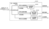
- FIG. 7 is a diagram showing the configuration of the first decoding unit 4640.
- FIG. 8 is a block diagram of the first decoding unit 4640.
- the first decoding unit 4640 generates point cloud data by decoding the coded data (coded stream) encoded by the first coding method by the first coding method.
- the first decoding unit 4640 includes a demultiplexing unit 4461, a position information decoding unit 4642, an attribute information decoding unit 4634, and an additional information decoding unit 4644.
- a coded stream (Compressed Stream), which is coded data, is input to the first decoding unit 4640 from a processing unit of a system layer (not shown).
- the demultiplexing unit 4641 separates the coded position information (Compressed Geometry), the coded attribute information (Compressed Attribute), the coded additional information (Compressed Metadata), and other additional information from the coded data.
- the position information decoding unit 4642 generates position information by decoding the coded position information. For example, the position information decoding unit 4642 restores the position information of the point cloud represented by the three-dimensional coordinates from the coded position information represented by the N-branch structure such as the ocree.
- the attribute information decoding unit 4643 decodes the coded attribute information based on the configuration information generated by the position information decoding unit 4642. For example, the attribute information decoding unit 4643 determines a reference point (reference node) to be referred to in decoding the target point (target node) to be processed, based on the octave tree structure obtained by the position information decoding unit 4642. For example, the attribute information decoding unit 4643 refers to a node whose parent node in the octree is the same as the target node among the peripheral nodes or adjacent nodes. The method of determining the reference relationship is not limited to this.
- the attribute information decoding process may include at least one of an inverse quantization process, a prediction process, and an arithmetic decoding process.
- the reference is the occupancy information indicating whether or not the reference node is used to calculate the predicted value of the attribute information, or the state of the reference node (for example, whether or not the reference node contains a point cloud) is used to determine the decoding parameters. ) Is used.
- the decoding parameter is a quantization parameter in the inverse quantization process, a context in arithmetic decoding, or the like.
- the additional information decoding unit 4644 generates additional information by decoding the coded additional information. Further, the first decoding unit 4640 uses the additional information necessary for the decoding process of the position information and the attribute information at the time of decoding, and outputs the additional information necessary for the application to the outside.
- FIG. 9 is a block diagram of the position information coding unit 2700 according to the present embodiment.
- the position information coding unit 2700 includes an octane tree generation unit 2701, a geometric information calculation unit 2702, a coding table selection unit 2703, and an entropy coding unit 2704.
- the ocree generation unit 2701 generates, for example, an ocree from the input position information, and generates an occupancy code for each node of the ocree.
- the geometric information calculation unit 2702 acquires information indicating whether or not the adjacent node of the target node is an occupied node. For example, the geometric information calculation unit 2702 calculates the occupancy information of the adjacent node (information indicating whether or not the adjacent node is the occupancy node) from the occupancy code of the parent node to which the target node belongs. Further, the geometric information calculation unit 2702 may save the encoded nodes in a list and search for adjacent nodes in the list. The geometric information calculation unit 2702 may switch the adjacent node according to the position in the parent node of the target node.
- the coding table selection unit 2703 selects a coding table to be used for entropy coding of the target node using the occupancy information of the adjacent node calculated by the geometric information calculation unit 2702. For example, the coded table selection unit 2703 may generate a bit string using the occupancy information of the adjacent node, and select the coded table of the index number generated from the bit string.
- the entropy coding unit 2704 generates coded position information and metadata by performing entropy coding on the occupancy code of the target node using the coded table of the selected index number.
- the entropy coding unit 2704 may add information indicating the selected coding table to the coding position information.
- the position information (position data) is converted into an octree structure (octree tree formation) and then encoded.
- the ocree tree structure consists of nodes and leaves. Each node has eight nodes or leaves, and each leaf has voxel (VXL) information.
- FIG. 10 is a diagram showing a structural example of position information including a plurality of voxels.
- FIG. 11 is a diagram showing an example in which the position information shown in FIG. 10 is converted into an octane tree structure.
- the leaves 1, 2 and 3 represent the voxels VXL1, VXL2 and VXL3 shown in FIG. 10, respectively, and represent the VXL including the point cloud (hereinafter, effective VXL).
- node 1 corresponds to the entire space including the position information of FIG.
- the entire space corresponding to node 1 is divided into eight nodes, and among the eight nodes, the node containing the valid VXL is further divided into eight nodes or leaves, and this process is repeated for the hierarchy of the tree structure.
- each node corresponds to a subspace, and has information (occupancy code) indicating at which position the next node or leaf is held after division as node information.
- the lowest block is set in the leaf, and the number of point clouds included in the leaf is held as leaf information.
- FIG. 12 is a block diagram of the position information decoding unit 2710 according to the present embodiment.
- the position information decoding unit 2710 includes an octane tree generation unit 2711, a geometric information calculation unit 2712, a coding table selection unit 2713, and an entropy decoding unit 2714.
- the ocree generation unit 2711 generates an ocree in a certain space (node) by using the header information or metadata of the bitstream. For example, the 8-minute tree generation unit 2711 generates a large space (root node) using the x-axis, y-axis, and z-axis directions of a certain space added to the header information, and uses that space as the x-axis. Eight small spaces A (nodes A0 to A7) are generated by dividing into two in the y-axis and z-axis directions, respectively, to generate an eight-minute tree. Further, nodes A0 to A7 are set in order as target nodes.
- the geometric information calculation unit 2712 acquires occupancy information indicating whether or not the node adjacent to the target node is an occupancy node. For example, the geometric information calculation unit 2712 calculates the occupancy information of the adjacent node from the occupancy code of the parent node to which the target node belongs. Further, the geometric information calculation unit 2712 may save the decoded nodes in a list and search for adjacent nodes in the list. The geometric information calculation unit 2712 may switch adjacent nodes according to the position of the target node in the parent node.
- the coding table selection unit 2713 selects a coding table (decoding table) to be used for entropy decoding of the target node using the occupancy information of the adjacent node calculated by the geometric information calculation unit 2712. For example, the coded table selection unit 2713 may generate a bit string using the occupancy information of the adjacent node and select the coded table of the index number generated from the bit string.
- a coding table decoding table
- the entropy decoding unit 2714 generates position information by entropy decoding the occupancy code of the target node using the selected coding table.
- the entropy decoding unit 2714 may decode and acquire the information of the selected coding table from the bit stream, and use the coding table indicated by the information to entropy-decode the occupancy code of the target node. ..
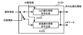
- FIG. 13 is a block diagram showing a configuration example of the attribute information coding unit A100.
- the attribute information coding unit may include a plurality of coding units that execute different coding methods.
- the attribute information encoding unit may switch between the following two methods according to the use case.
- the attribute information coding unit A100 includes a LoD attribute information coding unit A101 and a conversion attribute information coding unit A102.
- the LoD attribute information coding unit A101 classifies each three-dimensional point into a plurality of layers using the position information of the three-dimensional points, predicts the attribute information of the three-dimensional points belonging to each layer, and encodes the predicted residual. To become.
- each classified layer is referred to as LoD (Level of Detail).
- the conversion attribute information coding unit A102 encodes the attribute information using RAHT (Region Adaptive Hierarchical Transfer). Specifically, the conversion attribute information coding unit A102 generates high-frequency components and low-frequency components of each layer by applying RAHT or Har conversion to each attribute information based on the position information of the three-dimensional points. Then, those values are encoded by using quantization, entropy coding, or the like.
- RAHT Registered Adaptive Hierarchical Transfer
- FIG. 14 is a block diagram showing a configuration example of the attribute information decoding unit A110.
- the attribute information decoding unit may include a plurality of decoding units that execute different decoding methods. For example, the attribute information decoding unit may switch between the following two methods based on the information included in the header and metadata for decoding.
- the attribute information decoding unit A110 includes a LoD attribute information decoding unit A111 and a conversion attribute information decoding unit A112.
- the LoD attribute information decoding unit A111 classifies each three-dimensional point into a plurality of layers using the position information of the three-dimensional points, and decodes the attribute value while predicting the attribute information of the three-dimensional points belonging to each layer.
- the conversion attribute information decoding unit A112 decodes the attribute information using RAHT (Region Adaptive Hierarchical Transfer). Specifically, the conversion attribute information decoding unit A112 applies the invoke RAHT or invoke Haar conversion to the high-frequency component and the low-frequency component of each attribute value based on the position information of the three-dimensional point to obtain the attribute value. Decrypt.
- RAHT Restion Adaptive Hierarchical Transfer
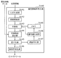
- FIG. 15 is a block diagram showing the configuration of the attribute information coding unit 3140, which is an example of the LoD attribute information coding unit A101.
- the attribute information coding unit 3140 includes a LoD generation unit 3141, a surrounding search unit 3142, a prediction unit 3143, a prediction residual calculation unit 3144, a quantization unit 3145, an arithmetic coding unit 3146, and an inverse quantization unit. It includes 3147, a decoding value generation unit 3148, and a memory 3149.
- LoD generation unit 3141 generates LoD using the position information of the three-dimensional point.
- the surrounding search unit 3142 searches for neighboring three-dimensional points adjacent to each three-dimensional point by using the LoD generation result by the LoD generation unit 3141 and the distance information indicating the distance between each three-dimensional point.
- the prediction unit 3143 generates a prediction value of the attribute information of the target three-dimensional point to be encoded.
- the predicted residual calculation unit 3144 calculates (generates) the predicted residual of the predicted value of the attribute information generated by the prediction unit 3143.
- the quantization unit 3145 quantizes the predicted residual of the attribute information calculated by the predicted residual calculation unit 3144.
- the arithmetic coding unit 3146 arithmetically encodes the predicted residual after being quantized by the quantization unit 3145.
- the arithmetic coding unit 3146 outputs a bit stream including the arithmetically coded predicted residual to, for example, a three-dimensional data decoding device.
- the predicted residual may be binarized by, for example, the quantization unit 3145 before being arithmetically coded by the arithmetic coding unit 3146.
- the arithmetic coding unit 3146 may initialize the coding table used for arithmetic coding before arithmetic coding.
- the arithmetic coding unit 3146 may initialize the coding table used for arithmetic coding for each layer.
- the arithmetic coding unit 3146 may include information indicating the position of the layer in which the coding table is initialized in the bit stream and output the information.
- the inverse quantization unit 3147 dequantizes the predicted residual after being quantized by the quantization unit 3145.
- the decoded value generation unit 3148 generates a decoded value by adding the predicted value of the attribute information generated by the prediction unit 3143 and the predicted residual after dequantization by the inverse quantization unit 3147.
- the memory 3149 is a memory that stores the decoded value of the attribute information of each three-dimensional point decoded by the decoded value generation unit 3148. For example, when the prediction unit 3143 generates a predicted value of an unencoded three-dimensional point, the prediction unit 3143 generates the predicted value by using the decoded value of the attribute information of each three-dimensional point stored in the memory 3149. ..
- FIG. 16 is a block diagram of the attribute information coding unit 6600, which is an example of the conversion attribute information coding unit A102.
- the attribute information coding unit 6600 includes a sorting unit 6601, a Har conversion unit 6602, a quantization unit 6603, an inverse quantization unit 6604, an inverse Haar conversion unit 6605, a memory 6606, and an arithmetic coding unit 6607. Be prepared.
- the sort unit 6601 generates a Morton code using the position information of the three-dimensional points, and sorts a plurality of three-dimensional points in the order of the Morton code.
- the Haar conversion unit 6602 generates a coding coefficient by applying the Haar conversion to the attribute information.
- the quantization unit 6603 quantizes the coding coefficient of the attribute information.
- the dequantization unit 6604 dequantizes the coding coefficient after quantization.
- the inverse Har conversion unit 6605 applies the inverse Har conversion to the coding coefficient.
- the memory 6606 stores the values of the attribute information of the plurality of decoded three-dimensional points. For example, the attribute information of the decoded three-dimensional point stored in the memory 6606 may be used for the prediction of the unencoded three-dimensional point and the like.
- the arithmetic coding unit 6607 calculates ZeroCnt from the coding coefficient after quantization, and arithmetically encodes ZeroCnt. In addition, the arithmetic coding unit 6607 arithmetically encodes the non-zero coding coefficient after quantization. The arithmetic coding unit 6607 may binarize the coding coefficient before arithmetic coding. Further, the arithmetic coding unit 6607 may generate and encode various header information.
- FIG. 17 is a block diagram showing the configuration of the attribute information decoding unit 3150, which is an example of the LoD attribute information decoding unit A111.
- the attribute information decoding unit 3150 includes a LoD generation unit 3151, a surrounding search unit 3152, a prediction unit 3153, an arithmetic decoding unit 3154, an inverse quantization unit 3155, a decoding value generation unit 3156, and a memory 3157. ..
- the LoD generation unit 3151 generates LoD using the position information of the three-dimensional points decoded by the position information decoding unit (not shown in FIG. 17).
- the surrounding search unit 3152 searches for neighboring three-dimensional points adjacent to each three-dimensional point by using the LoD generation result by the LoD generation unit 3151 and the distance information indicating the distance between each three-dimensional point.
- the prediction unit 3153 generates a predicted value of the attribute information of the target three-dimensional point to be decoded.
- the arithmetic decoding unit 3154 arithmetically decodes the predicted residual in the bit stream acquired from the attribute information coding unit 3140 shown in FIG.
- the arithmetic decoding unit 3154 may initialize the decoding table used for arithmetic decoding.
- the arithmetic decoding unit 3154 initializes the decoding table used for arithmetic decoding for the layer in which the arithmetic coding unit 3146 shown in FIG. 15 has been encoded.
- the arithmetic decoding unit 3154 may initialize the decoding table used for arithmetic decoding for each layer. Further, the arithmetic decoding unit 3154 may initialize the decoding table based on the information included in the bit stream indicating the position of the layer in which the coding table is initialized.
- the inverse quantization unit 3155 dequantizes the predicted residuals arithmetically decoded by the arithmetic decoding unit 3154.
- the decoding value generation unit 3156 adds the prediction value generated by the prediction unit 3153 and the prediction residual after dequantization by the inverse quantization unit 3155 to generate a decoding value.
- the decoded value generation unit 3156 outputs the decoded attribute information data to another device.
- the memory 3157 is a memory that stores the decoded value of the attribute information of each three-dimensional point decoded by the decoded value generation unit 3156. For example, when the prediction unit 3153 generates a predicted value of a three-dimensional point that has not been decoded yet, the prediction unit 3153 generates the predicted value by using the decoded value of the attribute information of each three-dimensional point stored in the memory 3157. ..
- FIG. 18 is a block diagram of the attribute information decoding unit 6610, which is an example of the conversion attribute information decoding unit A112.
- the attribute information decoding unit 6610 includes an arithmetic decoding unit 6611, an inverse quantization unit 6612, an inverse Har conversion unit 6613, and a memory 6614.
- the arithmetic decoding unit 6611 arithmetically decodes ZeroCnt and the coding coefficient included in the bit stream.
- the arithmetic decoding unit 6611 may decode various header information.
- the dequantization unit 6612 dequantizes the arithmetically decoded coding coefficient.
- the inverse Haar conversion unit 6613 applies the inverse Har conversion to the coding coefficient after the inverse quantization.
- the memory 6614 stores the values of the attribute information of the plurality of decoded three-dimensional points. For example, the attribute information of the decoded three-dimensional point stored in the memory 6614 may be used for predicting the undecoded three-dimensional point.
- FIG. 19 is a diagram showing the configuration of the second coding unit 4650.
- FIG. 20 is a block diagram of the second coding unit 4650.
- the second coding unit 4650 generates coded data (coded stream) by coding the point cloud data by the second coding method.
- the second coding unit 4650 includes an additional information generation unit 4651, a position image generation unit 4652, an attribute image generation unit 4653, a video coding unit 4654, an additional information coding unit 4655, and a multiplexing unit 4656. And include.
- the second coding unit 4650 generates a position image and an attribute image by projecting the three-dimensional structure onto the two-dimensional image, and encodes the generated position image and the attribute image using an existing video coding method. It has the feature.
- the second coding method is also called VPCC (Video based PCC).
- the point cloud data is PCC point cloud data such as a PLY file, or PCC point cloud data generated from sensor information, and provides position information (Position), attribute information (Attribute), and other additional information (MetaData).
- PCC point cloud data such as a PLY file, or PCC point cloud data generated from sensor information, and provides position information (Position), attribute information (Attribute), and other additional information (MetaData).
- the additional information generation unit 4651 generates map information of a plurality of two-dimensional images by projecting the three-dimensional structure onto the two-dimensional image.
- the position image generation unit 4652 generates a position image (Geometry Image) based on the position information and the map information generated by the additional information generation unit 4651.
- This position image is, for example, a distance image in which a distance (Dept) is shown as a pixel value.
- this distance image may be an image in which a plurality of point groups are viewed from one viewpoint (an image in which a plurality of point groups are projected on one two-dimensional plane), or a plurality of point groups from a plurality of viewpoints. It may be a plurality of images viewed, or it may be a single image in which these plurality of images are integrated.
- the attribute image generation unit 4653 generates an attribute image based on the attribute information and the map information generated by the additional information generation unit 4651.
- This attribute image is, for example, an image in which attribute information (for example, color (RGB)) is shown as a pixel value.
- RGB color
- this image may be an image in which a plurality of point groups are viewed from one viewpoint (an image in which a plurality of point groups are projected on one two-dimensional plane), or a plurality of point groups may be viewed from a plurality of viewpoints. It may be a plurality of images viewed, or it may be a single image in which these plurality of images are integrated.
- the video coding unit 4654 encodes the position image and the attribute image by using the video coding method, so that the coded position image (Compressed Geometry Image) and the coded attribute image (Compressed Attribute Image) which are the coded data are encoded. ) Is generated.
- the video coding method any known coding method may be used.
- the video coding method is AVC, HEVC, or the like.
- the additional information coding unit 4655 generates encoded additional information (Compressed Metadata Data) by encoding the additional information included in the point cloud data, the map information, and the like.
- the multiplexing unit 4656 generates a encoded stream (Compressed Stream) which is encoded data by multiplexing the encoded position image, the encoded attribute image, the encoded additional information, and other additional information.
- the generated coded stream is output to a processing unit of a system layer (not shown).
- FIG. 21 is a diagram showing a configuration of a second decoding unit 4660.
- FIG. 22 is a block diagram of the second decoding unit 4660.
- the second decoding unit 4660 generates point cloud data by decoding the coded data (coded stream) encoded by the second coding method by the second coding method.
- the second decoding unit 4660 includes a demultiplexing unit 4661, a video decoding unit 4662, an additional information decoding unit 4663, a position information generation unit 4664, and an attribute information generation unit 4665.
- a coded stream (Compressed Stream), which is coded data, is input to the second decoding unit 4660 from a processing unit of a system layer (not shown).
- the demultiplexing unit 4661 separates the coded position image (Compressed Geometry Image), the coded attribute image (Compressed Attribute Image), the coded additional information (Compressed Metadata Image), and other additional information from the coded data. ..
- the video decoding unit 4662 generates a position image and an attribute image by decoding the coded position image and the coded attribute image using a video coding method.
- a video coding method any known coding method may be used.
- the video coding method is AVC, HEVC, or the like.
- the additional information decoding unit 4663 generates additional information including map information and the like by decoding the coded additional information.
- the position information generation unit 4664 generates position information using the position image and the map information.
- the attribute information generation unit 4665 generates attribute information using the attribute image and the map information.
- the second decoding unit 4660 uses the additional information necessary for decoding at the time of decoding, and outputs the additional information necessary for the application to the outside.
- FIG. 23 is a diagram showing a protocol stack related to PCC coded data.
- FIG. 23 shows an example in which data of another medium such as video (for example, HEVC) or audio is multiplexed, transmitted or stored in PCC coded data.
- video for example, HEVC
- audio is multiplexed, transmitted or stored in PCC coded data.
- the multiplexing method and file format have a function for multiplexing, transmitting or accumulating various coded data.
- the coded data In order to transmit or store the coded data, the coded data must be converted to a multiplexing format.
- HEVC defines a technique for storing coded data in a data structure called a NAL unit and storing the NAL unit in ISOBMFF.
- a first coding method (Codec1) and a second coding method (Codec2) are being studied as a method for coding point group data.
- the method of storing in the system format is not defined, and there is a problem that MUX processing (multiplexing), transmission and storage in the coding unit cannot be performed as it is.
- the coded data (position information (Geometry), attribute information (Attribute), additional information (Metadata)) generated by the first coding unit 4630 or the second coding unit 4650 described above).
- the type of the data, the method of generating additional information (metadata), and the multiplexing process in the multiplexing unit will be described.
- the additional information (metadata) may be referred to as a parameter set or control information.
- the dynamic object (three-dimensional point cloud data that changes with time) described in FIG. 4 will be described as an example, but even in the case of a static object (three-dimensional point cloud data at an arbitrary time). A similar method may be used.
- FIG. 24 is a diagram showing a configuration of a coding unit 4801 and a multiplexing unit 4802 included in the three-dimensional data coding apparatus according to the present embodiment.
- the coding unit 4801 corresponds to, for example, the first coding unit 4630 or the second coding unit 4650 described above.
- the multiplexing unit 4802 corresponds to the multiplexing unit 4634 or 4656 described above.
- the coding unit 4801 encodes the point cloud data of a plurality of PCC (Point Cloud Compression) frames and generates coded data (Multiple Compressed Data) of a plurality of position information, attribute information and additional information.
- PCC Point Cloud Compression
- the multiplexing unit 4802 converts the data of a plurality of data types (position information, attribute information, and additional information) into a NAL unit, thereby converting the data into a data configuration in consideration of data access in the decoding device.
- FIG. 25 is a diagram showing a configuration example of coded data generated by the coding unit 4801.
- the arrow in the figure shows the dependency related to the decoding of the coded data, and the source of the arrow depends on the data at the tip of the arrow. That is, the decoding device decodes the data at the tip of the arrow, and uses the decoded data to decode the original data of the arrow.
- "dependence" means that the dependent data is referenced (used) in the processing (encoding or decoding, etc.) of the dependent data.
- the coding unit 4801 encodes the position information of each frame to generate coded position data (Compressed Geometry Data) for each frame.
- the coded position data is represented by G (i). i indicates a frame number, a frame time, or the like.
- the coding unit 4801 generates a position parameter set (GPS (i)) corresponding to each frame.
- the position parameter set contains parameters that can be used to decode the coded position data. Also, the coded position data for each frame depends on the corresponding position parameter set.
- the coded position data composed of a plurality of frames is defined as a position sequence (Geometry Sequence).
- the coding unit 4801 generates a position sequence parameter set (also referred to as Geometry Sequence PS: position SPS) that stores parameters commonly used for decoding processing for a plurality of frames in the position sequence.
- the position sequence depends on the position SPS.
- the coding unit 4801 encodes the attribute information of each frame to generate the coded attribute data (Compressed Attribute Data) for each frame.
- the coded attribute data is represented by A (i).
- FIG. 25 shows an example in which the attribute X and the attribute Y exist, the coded attribute data of the attribute X is represented by AX (i), and the coded attribute data of the attribute Y is represented by AY (i). ..
- the coding unit 4801 generates an attribute parameter set (APS (i)) corresponding to each frame.
- the attribute parameter set of the attribute X is represented by AXPS (i)
- the attribute parameter set of the attribute Y is represented by AYPS (i).
- the attribute parameter set contains parameters that can be used to decode the coded attribute information.
- the coded attribute data depends on the corresponding set of attribute parameters.
- the coded attribute data consisting of a plurality of frames is defined as an attribute sequence (Attribute Sequence).
- the coding unit 4801 generates an attribute sequence parameter set (Attribute Sequence PS: also referred to as attribute SPS) that stores parameters commonly used for decoding processing for a plurality of frames in the attribute sequence.
- attribute sequence PS also referred to as attribute SPS
- the attribute sequence depends on the attribute SPS.
- the coding attribute data depends on the coding position data.
- FIG. 25 shows an example in which two types of attribute information (attribute X and attribute Y) exist.
- attribute information for example, the respective data and metadata are generated by the two coding units.
- an attribute sequence is defined for each type of attribute information, and an attribute SPS is generated for each type of attribute information.
- FIG. 25 shows an example in which the position information is one type and the attribute information is two types, but the present invention is not limited to this, and the attribute information may be one type or three or more types. good.
- the coded data can be generated by the same method.
- the attribute information may not be present. In that case, the coding unit 4801 does not have to generate the parameter set related to the attribute information.
- the coding unit 4801 generates a PCC stream PS (PCC Stream PS: also referred to as a stream PS), which is a parameter set for the entire PCC stream.
- the coding unit 4801 stores in the stream PS parameters that can be commonly used in the decoding process for one or more position sequences and one or more attribute sequences.
- the stream PS includes identification information indicating the codec of the point cloud data, information indicating the algorithm used for encoding, and the like.
- the position sequence and attribute sequence depend on the stream PS.
- An access unit is a basic unit for accessing data at the time of decryption, and is composed of one or more data and one or more metadata.
- the access unit is composed of position information at the same time and one or more attribute information.
- a GOF is a random access unit and is composed of one or more access units.
- the coding unit 4801 generates an access unit header (AU Header) as identification information indicating the head of the access unit.
- the coding unit 4801 stores the parameters related to the access unit in the access unit header.
- the access unit header contains the structure or information of the coded data contained in the access unit.
- the access unit header includes parameters commonly used for data included in the access unit, for example, parameters related to decoding of coded data.
- the coding unit 4801 may generate an access unit delimiter that does not include parameters related to the access unit instead of the access unit header.
- This access unit delimiter is used as identification information indicating the head of the access unit.
- the decoding device identifies the head of the access unit by detecting the access unit header or the access unit delimiter.
- the coding unit 4801 generates a GOF header (GOF Header) as identification information indicating the beginning of the GOF.
- the coding unit 4801 stores the parameters related to the GOF in the GOF header.
- the GOF header contains the structure or information of the coded data contained in the GOF.
- the GOF header includes parameters commonly used for the data included in the GOF, for example, parameters related to decoding of the coded data.
- the coding unit 4801 may generate a GOF delimiter that does not include the parameters related to the GOF instead of the GOF header.
- This GOF delimiter is used as identification information indicating the beginning of the GOF.
- the decoding device identifies the beginning of the GOF by detecting the GOF header or the GOF delimiter.
- the access unit is defined as a PCC frame unit.
- the decoding device accesses the PCC frame based on the identification information at the head of the access unit.
- GOF is defined as one random access unit.
- the decoding device accesses the random access unit based on the identification information at the head of the GOF.
- a PCC frame may be defined as a random access unit as long as the PCC frames do not depend on each other and can be decoded independently.
- one access unit may be assigned two or more PCC frames, or one GOF may be assigned a plurality of random access units.
- the coding unit 4801 may define and generate a parameter set or metadata other than the above.
- the coding unit 4801 may generate SEI (Supplemental Enchanment Information) that stores parameters (optional parameters) that may not necessarily be used at the time of decoding.
- SEI Supplemental Enchanment Information
- FIG. 26 is a diagram showing an example of coded data and a NAL unit.
- the coded data includes a header and a payload.
- the coded data may include length information indicating the length (data amount) of the coded data, the header or the payload. Further, the coded data does not have to include a header.
- the header contains, for example, identification information for identifying data.
- This identification information indicates, for example, a data type or a frame number.
- the header contains, for example, identification information indicating a reference relationship. This identification information is stored in the header when there is a dependency between the data, for example, and is information for referencing the reference destination from the reference source.
- the referenced header contains identification information for identifying the data.
- the header of the reference source includes identification information indicating the reference destination.
- the identification information for specifying the data or the identification information indicating the reference relationship may be omitted.
- the multiplexing unit 4802 stores the coded data in the payload of the NAL unit.
- the NAL unit header includes pcc_nal_unit_type, which is identification information of the coded data.
- FIG. 27 is a diagram showing an example of the semantics of pcc_nal_unit_type.
- pcc_codec_type is codec 1 (Codec1: first coding method)
- the values 0 to 10 of pcc_naal_unit_type are codec position data (Geometry) and coding attribute X data in codec 1.
- HeaderX Codec Attribute Y Data (HeaderY), Position PS (Geom.PS), Attribute XPS (AttrX.PS), Attribute YPS (AttrX.PS), Position SPS (Geometry Sequence PS), Attribute XSPS (HeaderX) It is assigned to PS), attribute YSPS (AttributeY Position PS), AU header (AU Header), and GOF header (GOF Header). Further, the value 11 or later is assigned to the reserve of the codec 1.
- pcc_codec_type is codec 2 (Codec 2: second coding method)
- the values 0 to 2 of pcc_nal_unit_type are assigned to codec data A (DataA), metadata A (MetaDataA), and metadata B (MetaDataB). .. Further, the value 3 or later is assigned to the reserve of the codec 2.
- the multiplexing unit 4802 collectively sends out the NAL unit in units of GOF or AU.
- the multiplexing unit 4802 arranges the GOF header at the head of the GOF and the AU header at the head of the AU.
- the multiplexing unit 4802 may arrange a sequence parameter set (SPS) for each AU so that the decoding device can decode from the next AU.
- SPS sequence parameter set
- the decoding device decodes the referenced data and then decodes the reference source data. In order to enable the decoding device to decode the data in the order in which they are received without rearranging the data, the multiplexing unit 4802 sends the referenced data first.
- FIG. 28 is a diagram showing an example of the sending order of the NAL unit.
- FIG. 28 shows three examples of location information priority, parameter priority, and data integration.
- the location information priority transmission order is an example of transmitting information related to position information and information related to attribute information together. In the case of this transmission order, the transmission of the information regarding the position information is completed earlier than the transmission of the information regarding the attribute information.
- a decoding device that does not decode the attribute information may be able to set a time for not processing by ignoring the decoding of the attribute information. Further, for example, in the case of a decoding device that wants to decode the position information quickly, there is a possibility that the position information can be decoded faster by obtaining the coded data of the position information earlier.
- the attribute XSPS and the attribute YSPS are integrated and described as the attribute SPS, but the attribute XSPS and the attribute YSPS may be arranged separately.
- the parameter set is transmitted first and the data is transmitted later.
- the multiplexing unit 4802 may transmit the NAL units in any order.
- the order identification information is defined, and the multiplexing unit 4802 may have a function of sending out NAL units in the order of a plurality of patterns.
- the order identification information of the NAL unit is stored in the stream PS.
- the three-dimensional data decoding device may perform decoding based on the order identification information.
- the three-dimensional data decoding device may instruct the three-dimensional data coding device of the desired transmission order, and the three-dimensional data coding device (multiplexing unit 4802) may control the transmission order according to the instructed transmission order.
- the multiplexing unit 4802 may generate coded data in which a plurality of functions are merged as long as the transmission order is restricted, such as the transmission order of data integration.
- the GOF header and the AU header may be integrated, or the AXIS and the AYPS may be integrated.
- an identifier indicating that the data has a plurality of functions is defined in pcc_nal_unit_type.
- the parameter storage method is The following method may be used.
- the default PS value is indicated by the higher PS.
- the value of PS is indicated by the lower PS.
- the PS value is not described in the upper PS, and the PS value is described in the lower PS.
- the information on whether the value of PS is indicated by the lower PS, the upper PS, or both is indicated in one or both of the lower PS and the upper PS.
- the lower PS may be merged with the upper PS.
- the multiplexing unit 4802 may omit the transmission of either one.
- the coding unit 4801 or the multiplexing unit 4802 may divide the data into slices, tiles, or the like, and send out the divided data.
- the divided data contains information for identifying the divided data, and the parameters used for decoding the divided data are included in the parameter set.
- pcc_nal_unit_type an identifier indicating that the data or parameters related to the tile or slice are stored is defined.
- FIG. 29 is a flowchart of processing by the three-dimensional data coding apparatus (encoding unit 4801 and multiplexing unit 4802) relating to the transmission order of the NAL unit.
- the three-dimensional data encoding device determines the transmission order (position information priority or parameter set priority) of the NAL unit (S4801). For example, the three-dimensional data coding device determines the transmission order based on the designation from the user or an external device (for example, a three-dimensional data decoding device).
- the three-dimensional data encoding device sets the order identification information included in the stream PS to position information priority (S4803). That is, in this case, the order identification information indicates that the NAL units are sent in the order in which the position information is prioritized. Then, the three-dimensional data coding device sends out the NAL units in the order of prioritizing the position information (S4804).
- the three-dimensional data encoding device sets the order identification information included in the stream PS to parameter set priority (S4805). That is, in this case, the order identification information indicates that the NAL units are sent in the order in which the parameter set is prioritized. Then, the three-dimensional data coding apparatus sends out NAL units in the order of parameter set parameter set priority (S4806).
- FIG. 30 is a flowchart of processing by the three-dimensional data decoding device related to the transmission order of the NAL unit.
- the three-dimensional data decoding device analyzes the order identification information included in the stream PS (S4811).
- the three-dimensional data decoding device decodes the NAL unit assuming that the transmission order of the NAL unit is position information priority (S4812). S4813).
- the three-dimensional data decoding device decodes the NAL unit assuming that the transmission order of the NAL unit has parameter set priority. (S4814).
- step S4813 the NAL unit related to the position information is acquired without acquiring all the NAL units, and the position information is decoded from the acquired NAL unit. May be good.
- FIG. 31 is a flowchart of processing by a three-dimensional data coding device (multiplexing unit 4802) related to AU and GOF generation in multiplexing of NAL units.
- the three-dimensional data coding device determines the type of coded data (S4821). Specifically, the three-dimensional data coding apparatus determines whether the coded data to be processed is the data at the head of the AU, the data at the head of the GOF, or other data.
- the three-dimensional data coding device arranges the GOF header and the AU header at the head of the coded data belonging to the GOF to generate a NAL unit (the head of the GOF). S4823).
- the three-dimensional data coding device arranges the AU header at the head of the coded data belonging to the AU to generate the NAL unit (S4824).
- the three-dimensional data encoding device places the coded data after the AU header of the AU to which the coded data belongs. To generate a NAL unit (S4825).
- FIG. 32 is a flowchart of the processing of the three-dimensional data decoding device related to the access of AU and GOF in the demultiplexing of the NAL unit.
- the three-dimensional data decoding device determines the type of coded data included in the NAL unit by analyzing the nal_unit_type included in the NAL unit (S4831). Specifically, the three-dimensional data decoding device determines whether the coded data included in the NAL unit is the data at the head of the AU, the data at the head of the GOF, or other data.
- the three-dimensional data decoding device determines that the NAL unit is the start position of random access and accesses the NAL unit. Then, the decoding process is started (S4833).
- the three-dimensional data decoding device determines that the NAL unit is the AU head, and the data included in the NAL unit. To decode the AU (S4834).
- the three-dimensional data decoding device does not process the NAL unit. Twice
- FIG. 33 is a block diagram showing the configuration of the first coding unit 4910 included in the three-dimensional data coding device according to the present embodiment.
- the first coding unit 4910 generates coded data (coded stream) by coding the point cloud data by the first coding method (GPCC (Geometry based PCC)).
- the first coding unit 4910 includes a dividing unit 4911, a plurality of position information coding units 4912, a plurality of attribute information coding units 4913, an additional information coding unit 4914, and a multiplexing unit 4915. ..
- the division unit 4911 generates a plurality of division data by dividing the point cloud data. Specifically, the division unit 4911 generates a plurality of division data by dividing the space of the point cloud data into a plurality of subspaces.
- the subspace is one of tiles and slices, or a combination of tiles and slices.
- the point cloud data includes position information, attribute information, and additional information.
- the division unit 4911 divides the position information into a plurality of division position information, and divides the attribute information into a plurality of division attribute information. In addition, the division unit 4911 generates additional information regarding the division.
- the plurality of position information coding units 4912 generate a plurality of coded position information by encoding the plurality of divided position information. For example, the plurality of position information coding units 4912 process a plurality of divided position information in parallel.
- the plurality of attribute information coding units 4913 generate a plurality of coded attribute information by encoding the plurality of divided attribute information. For example, the plurality of attribute information encoding units 4913 process a plurality of divided attribute information in parallel.
- the additional information coding unit 4914 generates coded additional information by encoding the additional information included in the point cloud data and the additional information related to the data division generated at the time of division by the division unit 4911.
- the multiplexing unit 4915 generates coded data (coded stream) by multiplexing a plurality of coded position information, a plurality of coded attribute information, and coded additional information, and transmits the generated coded data. ..
- the coded additional information is used at the time of decoding.
- the numbers of the position information coding unit 4912 and the attribute information coding unit 4913 show two examples, respectively, but the numbers of the position information coding unit 4912 and the attribute information coding unit 4913 are respectively. It may be one or three or more. Further, the plurality of divided data may be processed in parallel in the same chip like a plurality of cores in the CPU, may be processed in parallel by the cores of a plurality of chips, or may be processed in parallel by a plurality of cores of a plurality of chips. May be done.
- FIG. 34 is a block diagram showing the configuration of the first decoding unit 4920.
- the first decoding unit 4920 restores the point cloud data by decoding the coded data (encoded stream) generated by encoding the point cloud data by the first coding method (GPCC). ..
- the first decoding unit 4920 includes a demultiplexing unit 4921, a plurality of position information decoding units 4922, a plurality of attribute information decoding units 4923, an additional information decoding unit 4924, and a coupling unit 4925.
- the demultiplexing unit 4921 generates a plurality of coded position information, a plurality of coded attribute information, and coded additional information by demultiplexing the coded data (coded stream).
- the plurality of position information decoding units 4922 generate a plurality of divided position information by decoding the plurality of coded position information. For example, the plurality of position information decoding units 4922 process a plurality of coded position information in parallel.
- the plurality of attribute information decoding units 4923 generates a plurality of divided attribute information by decoding the plurality of coded attribute information. For example, the plurality of attribute information decoding units 4923 processes a plurality of coded attribute information in parallel.
- the plurality of additional information decoding units 4924 generate additional information by decoding the coded additional information.
- the connecting unit 4925 generates position information by combining a plurality of divided position information using additional information.
- the connecting unit 4925 generates attribute information by combining a plurality of divided attribute information using additional information.
- the number of the position information decoding unit 4922 and the number of the attribute information decoding unit 4923 are two, respectively, but the number of the position information decoding unit 4922 and the attribute information decoding unit 4923 is one, respectively. It may be three or more. Further, the plurality of divided data may be processed in parallel in the same chip as in the case of the plurality of cores in the CPU, or may be processed in parallel by the cores of the plurality of chips, or may be processed in parallel by the plurality of cores of the plurality of chips. You may.
- FIG. 35 is a block diagram of the divided portion 4911.
- the division unit 4911 includes a slice division unit 4931 (Slice Divider), a position information tile division unit 4932 (Geometry Tile Divider), and an attribute information tile division unit 4933 (Attribute Tile Divider).
- the slice division unit 4931 generates a plurality of slice position information by dividing the position information (Position (Geometry)) into slices. Further, the slice division unit 4931 generates a plurality of slice attribute information by dividing the attribute information (Attribute) into slices. Further, the slice division unit 4931 outputs the slice addition information (SliceMetaData) including the information related to the slice division and the information generated in the slice division.
- the position information tile division unit 4932 generates a plurality of division position information (a plurality of tile position information) by dividing a plurality of slice position information into tiles. Further, the position information tile division unit 4932 outputs the position tile additional information (Geometry Tile Metadata Data) including the information related to the tile division of the position information and the information generated in the tile division of the position information.
- a plurality of division position information a plurality of tile position information
- the position information tile division unit 4932 outputs the position tile additional information (Geometry Tile Metadata Data) including the information related to the tile division of the position information and the information generated in the tile division of the position information.
- the attribute information tile division unit 4933 generates a plurality of division attribute information (a plurality of tile attribute information) by dividing a plurality of slice attribute information into tiles. Further, the attribute information tile division unit 4933 outputs the attribute tile additional information (Attribute Tile MetaData) including the information related to the tile division of the attribute information and the information generated in the tile division of the attribute information.
- attribute tile additional information Attribute Tile MetaData
- the number of slices or tiles to be divided is 1 or more. That is, it is not necessary to slice or divide the tile.
- the slice division may be performed after the tile division.
- a new division type may be defined, and division may be performed with three or more division types.
- FIG. 36 is a diagram showing an example of slicing and tile division.
- the division unit 4911 divides the three-dimensional point cloud data into an arbitrary point cloud in slice units.
- the division unit 4911 does not divide the position information and the attribute information constituting the points, but divides the position information and the attribute information at once. That is, the division unit 4911 performs slice division so that the position information and the attribute information at an arbitrary point belong to the same slice.
- the number of divisions and the division method may be any method.
- the minimum unit of division is a point.
- the number of divisions between the position information and the attribute information is the same.
- the three-dimensional point corresponding to the position information after the slice division and the three-dimensional point corresponding to the attribute information are included in the same slice.
- the division unit 4911 generates slice addition information which is additional information related to the number of divisions and the division method at the time of slice division.
- the slice addition information is the same for the position information and the attribute information.
- the slice addition information includes information indicating the reference coordinate position, size, or side length of the bounding box after division. Further, the slice addition information includes information indicating the number of divisions, the division type, and the like.
- the division unit 4911 divides the slice-divided data into slice position information (G slice) and slice attribute information (A slice), and divides the slice position information and slice attribute information into tile units, respectively.
- FIG. 36 shows an example of dividing by an octa-tree structure
- the number of divisions and the division method may be any method.
- the division unit 4911 may divide the position information and the attribute information by different division methods, or may divide by the same division method. Further, the division unit 4911 may divide a plurality of slices into tiles by different division methods, or may divide them into tiles by the same division method.
- the division unit 4911 generates tile addition information related to the number of divisions and the division method at the time of tile division.
- the tile addition information (position tile addition information and attribute tile addition information) is independent of the position information and the attribute information.
- the tile addition information includes information indicating the reference coordinate position, size, or side length of the bounding box after division. Further, the tile addition information includes information indicating the number of divisions, the division type, and the like.
- the division unit 4911 may use a predetermined method as the method of slicing or tile division, or may adaptively switch the method to be used according to the point cloud data.
- the division unit 4911 collectively divides the three-dimensional space with respect to the position information and the attribute information. For example, the division unit 4911 determines the shape of the object and divides the three-dimensional space into slices according to the shape of the object. For example, the division unit 4911 extracts an object such as a tree or a building and divides the object unit. For example, the division unit 4911 performs slice division so that the entire one or a plurality of objects are included in one slice. Alternatively, the division unit 4911 divides one object into a plurality of slices.
- the coding apparatus may change the coding method for each slice, for example.
- the encoding device may use a high quality compression method for a particular object or a particular part of the object.
- the coding apparatus may store information indicating the coding method for each slice in additional information (metadata).
- the division unit 4911 may perform slice division so that each slice corresponds to a predetermined coordinate space based on the map information or the position information.
- the division unit 4911 independently divides the position information and the attribute information. For example, the division unit 4911 divides the slice into tiles according to the amount of data or the amount of processing. For example, the division unit 4911 determines whether the amount of data in the slice (for example, the number of three-dimensional points contained in the slice) is larger than a predetermined threshold value. The dividing unit 4911 divides the slice into tiles when the amount of data of the slice is larger than the threshold value. The dividing unit 4911 does not divide the slice into tiles when the amount of data in the slice is less than the threshold value.
- the dividing unit 4911 divides the slice into tiles so that the processing amount or processing time in the decoding device is within a certain range (less than or equal to a predetermined value). As a result, the amount of processing per tile in the decoding device becomes constant, and distributed processing in the decoding device becomes easy.
- the division unit 4911 sets the number of divisions of the position information from the number of divisions of the attribute information. Do more.
- the division unit 4911 determines the number of divisions of the position information. It may be larger than the number of divisions of the attribute information. As a result, the decoding device can increase the number of parallel positions of the position information, so that the processing of the position information can be made faster than the processing of the attribute information.
- the decoding device does not necessarily have to process the sliced or tiled data in parallel, and may determine whether or not to process these in parallel according to the number or capacity of the decoding processing units.
- adaptive coding according to the content or object can be realized.
- parallel processing in decoding processing can be realized. This increases the flexibility of the point cloud coding system or the point cloud decoding system.
- FIG. 37 is a diagram showing an example of a pattern of slicing and dividing tiles.
- the DU in the figure is a data unit (DataUnit) and indicates tile or slice data.
- each DU includes a slice index (SliceIndex) and a tile index (TileIndex).
- sliceIndex slice index
- TileIndex tile index
- the numerical value on the upper right of the DU in the figure indicates the slice index
- the numerical value on the lower left of the DU indicates the tile index.
- the number of divisions and the division method are the same for G slice and A slice.
- the number of divisions and the division method for the G slice and the division number and the division method for the A slice are different. Further, the same number of divisions and division methods are used between a plurality of G slices. The same number of divisions and division methods are used between a plurality of A slices.
- the number of divisions and the division method are the same for the G slice and the A slice.
- the number of divisions and the division method for the G slice and the division number and the division method for the A slice are different. Further, the number of divisions and the division method are different among the plurality of G slices. The number of divisions and the division method are different among a plurality of A slices.
- the three-dimensional data coding device (first coding unit 4910) encodes each of the divided data.
- the three-dimensional data coding device When encoding the attribute information, the three-dimensional data coding device generates dependency information as additional information indicating which configuration information (position information, additional information, or other attribute information) was used for coding. .. That is, the dependency information indicates, for example, the configuration information of the reference destination (dependency destination).
- the three-dimensional data encoding device generates dependency information based on the configuration information corresponding to the divided shape of the attribute information.
- the three-dimensional data coding device may generate dependency information based on the configuration information corresponding to the plurality of divided shapes.
- Dependency information may be generated by a 3D data encoding device, and the generated dependency information may be sent to a 3D data decoding device.
- the 3D data decoding device does not have to generate the dependency information, and the 3D data coding device does not have to send the dependency information.
- the dependency relationship used by the three-dimensional data coding device is defined in advance, and the three-dimensional data coding device does not have to send out the dependency relationship information.
- FIG. 38 is a diagram showing an example of the dependency relationship of each data.
- the tip of the arrow in the figure indicates the dependency destination, and the source of the arrow indicates the dependency source.
- the three-dimensional data decoding device decodes data in the order of the dependency source from the dependency destination. Further, the data indicated by the solid line in the figure is the data actually transmitted, and the data indicated by the dotted line is the data not transmitted.
- G indicates position information and A indicates attribute information.
- G s1 indicates the position information of the slice number 1
- G s2 indicates the position information of the slice number 2.
- G s1t1 indicates the position information of slice number 1 and tile number 1
- G s1t2 indicates the position information of slice number 1 and tile number 2
- G s2t1 indicates the position information of slice number 2 and tile number 1.
- G s2t2 indicate the position information of the slice number 2 and the tile number 2.
- a s1 indicates the attribute information of the slice number 1
- a s2 indicates the attribute information of the slice number 2.
- As1t1 indicates the attribute information of slice number 1 and tile number 1
- As1t2 indicates the attribute information of slice number 1 and tile number 2
- As2t1 indicates the attribute information of slice number 2 and tile number 1.
- As2t2 indicate the attribute information of the slice number 2 and the tile number 2.
- Mslice indicates slice addition information
- MGtile indicates position tile addition information
- MAtile indicates attribute tile addition information
- D s1t1 shows the dependency information of the attribute information A s1t1
- D s2t1 shows the dependency information of the attribute information A s2t1 .
- the three-dimensional data coding device may sort the data in the decoding order so that the data does not need to be sorted in the three-dimensional data decoding device.
- the data may be rearranged in the three-dimensional data decoding device, or the data may be rearranged in both the three-dimensional data coding device and the three-dimensional data decoding device.
- FIG. 39 is a diagram showing an example of the data decoding order.
- decoding is performed in order from the left data.
- the three-dimensional data decoding device decodes the dependent data first among the dependent data.
- the three-dimensional data coding apparatus rearranges the data in advance so as to send the data in this order. Any order may be used as long as the dependent data comes first. Further, the three-dimensional data coding apparatus may send additional information and dependency information before the data.
- FIG. 40 is a flowchart showing the flow of processing by the three-dimensional data coding device.
- the three-dimensional data coding apparatus encodes the data of a plurality of slices or tiles as described above (S4901).
- the three-dimensional data coding apparatus rearranges the data so that the dependent data comes first (S4902).
- the three-dimensional data coding apparatus multiplexes (NAL unitizes) the sorted data (S4903).
- FIG. 41 is a block diagram showing the configuration of the coupling portion 4925.
- the connecting portion 4925 includes a position information tile connecting portion 4941 (Geometry Tile Comminer), an attribute information tile connecting portion 4942 (Attribute Tile Comminer), and a slice connecting portion (Slice Comminer).
- the position information tile connecting unit 4941 generates a plurality of slice position information by combining a plurality of divided position information using the position tile additional information.
- the attribute information tile connecting unit 4942 generates a plurality of slice attribute information by combining a plurality of divided attribute information using the attribute tile addition information.
- the slice joining unit 4943 generates position information by joining a plurality of slice position information using the slice addition information. Further, the slice connection unit 4943 generates attribute information by combining a plurality of slice attribute information using the slice addition information.
- the number of slices or tiles to be divided is 1 or more. That is, the slices or tiles may not be divided.
- the slice division may be performed after the tile division.
- a new division type may be defined, and division may be performed with three or more division types.
- FIG. 42 is a diagram showing a configuration of coded data and a method of storing the coded data in the NAL unit.
- the coded data (division position information and division attribute information) is stored in the payload of the NAL unit.
- the coded data includes a header and a payload.
- the header contains identification information for identifying the data contained in the payload.
- This identification information includes, for example, the type of slice division or tile division (slice_type, tile_type), index information (slice_idx, tile_idx) for identifying a slice or tile, position information of data (slice or tile), or data address. (Addless) and the like are included.
- the index information for identifying the slice is also referred to as a slice index (SliceIndex).
- the index information for identifying the tile is also referred to as a tile index (TileIndex).
- the type of division is, for example, a method based on the object shape as described above, a method based on map information or position information, a method based on the amount of data or the amount of processing, and the like.
- the above information is stored in one of the header of the division position information and the header of the division attribute information, and may not be stored in the other.
- the division type (slice_type, tile_type) and the index information (slice_idx, tile_idx) are the same for the position information and the attribute information. Therefore, these pieces of information may be included in one of the headers of the position information and the attribute information.
- the attribute information depends on the position information
- the position information is processed first. Therefore, it is not necessary that the header of the position information includes such information and the header of the attribute information does not include such information.
- the three-dimensional data decoding device determines that the attribute information of the dependency source belongs to the same slice or tile as the slice or tile of the position information of the dependency destination, for example.
- additional information related to slice division or tile division is the existing parameter sets (GPS, APS, position SPS, or It may be stored in the attribute SPS (etc.) and sent out.
- information indicating the division method may be stored in a parameter set (GPS, APS, etc.) for each frame. If the division method does not change within the sequence, information indicating the division method may be stored in the parameter set (position SPS or attribute SPS) for each sequence. Further, when the same division method is used for the position information and the attribute information, the information indicating the division method may be stored in the parameter set (stream PS) of the PCC stream.
- the above information may be stored in any one of the above parameter sets, or may be stored in a plurality of parameter sets. Further, a parameter set for tile division or slice division may be defined, and the above information may be stored in the parameter set. Further, these pieces of information may be stored in the header of the coded data.
- the header of the coded data includes identification information indicating the dependency. That is, the header includes identification information for referencing the dependency destination from the dependency source when there is a dependency relationship between the data.
- the header of the dependent data includes identification information for identifying the data.
- the header of the data of the dependency source includes identification information indicating the dependency destination. If the identification information for specifying the data, the additional information related to the slice division or the tile division, and the identification information indicating the dependency can be identified or derived from other information, these information are omitted. You may.
- FIG. 43 is a flowchart of the point cloud data coding process according to the present embodiment.
- the three-dimensional data coding device determines the division method to be used (S4911).
- This division method includes whether or not to perform slice division and whether or not to perform tile division. Further, the division method may include the number of divisions when performing slice division or tile division, the type of division, and the like.
- the type of division is a method based on the object shape as described above, a method based on map information or position information, a method based on the amount of data or the amount of processing, and the like.
- the division method may be predetermined.
- the three-dimensional data encoding device When slice division is performed (Yes in S4912), the three-dimensional data encoding device generates a plurality of slice position information and a plurality of slice attribute information by collectively dividing the position information and the attribute information (S4913). .. In addition, the three-dimensional data coding device generates slice addition information related to slice division. The three-dimensional data coding device may independently divide the position information and the attribute information.
- the three-dimensional data encoding device divides a plurality of slice position information and a plurality of slice attribute information (or position information and attribute information) independently to obtain a plurality of division positions. Information and a plurality of division attribute information are generated (S4915). Further, the three-dimensional data encoding device generates position tile addition information and attribute tile addition information related to tile division.
- the three-dimensional data coding apparatus may collectively divide the slice position information and the slice attribute information.
- the three-dimensional data coding apparatus generates a plurality of coded position information and a plurality of coded attribute information by encoding each of the plurality of divided position information and the plurality of divided attribute information (S4916). ..
- the three-dimensional data coding device generates dependency information.
- the three-dimensional data coding device generates coded data (coded stream) by NAL unitizing (multiplexing) a plurality of coded position information, a plurality of coded attribute information, and additional information (multiplexed). S4917). In addition, the three-dimensional data coding device sends out the generated coded data.
- FIG. 44 is a flowchart of the point cloud data decoding process according to the present embodiment.
- the three-dimensional data decoding device analyzes the additional information (slice additional information, position tile additional information, and attribute tile additional information) related to the division method included in the coded data (encoded stream), thereby performing the division method. Is determined (S4921).
- This division method includes whether or not to perform slice division and whether or not to perform tile division. Further, the division method may include the number of divisions when performing slice division or tile division, the type of division, and the like.
- the three-dimensional data decoding device decodes a plurality of coded position information and a plurality of coded attribute information included in the coded data by using the dependency information included in the coded data to obtain the divided position information. And the division attribute information is generated (S4922).
- the three-dimensional data decoding device When the additional information indicates that the tile division is performed (Yes in S4923), the three-dimensional data decoding device has a plurality of division position information and a plurality of divisions based on the position tile addition information and the attribute tile addition information. By combining the attribute information with each method, a plurality of slice position information and a plurality of slice attribute information are generated (S4924). The three-dimensional data decoding device may combine the plurality of division position information and the plurality of division attribute information by the same method.
- the three-dimensional data decoding apparatus When the additional information indicates that the slice division is performed (Yes in S4925), the three-dimensional data decoding apparatus has a plurality of slice position information and a plurality of slice attribute information (a plurality of division positions) based on the slice addition information. Information and a plurality of divided attribute information) are combined in the same way to generate position information and attribute information (S4926).
- the three-dimensional data decoding device may combine the plurality of slice position information and the plurality of slice attribute information by different methods.
- the three-dimensional data encoding device includes a plurality of divided data in which a target space containing a plurality of three-dimensional points is included in a plurality of divided subspaces (for example, slices), each containing one or more three-dimensional points. It is divided into (for example, tiles) (S4932).
- the divided data is one or more data aggregates included in the subspace and including one or more three-dimensional points.
- the divided data is also a space, and may include a space that does not include three-dimensional points.
- one subspace may contain a plurality of divided data, or one subspace may contain one divided data. A plurality of subspaces may be set in the target space, or one subspace may be set in the target space.
- the three-dimensional data encoding device encodes each of the plurality of partitioned data to generate a plurality of encoded data corresponding to each of the plurality of partitioned data (S4931).
- the three-dimensional data coding apparatus generates a bit stream including a plurality of coded data and a plurality of control information (for example, a header shown in FIG. 42) for each of the plurality of coded data (S4932).
- Each of the plurality of control information indicates a first identifier (for example, slice_idx) indicating a subspace corresponding to the coded data corresponding to the control information, and divided data corresponding to the coded data corresponding to the control information.
- a second identifier for example, tile_idx is stored.
- the three-dimensional data decoding apparatus that decodes the bit stream generated by the three-dimensional data encoding apparatus uses the first identifier and the second identifier to combine the data of a plurality of divided data to form the target space. Can be easily restored. Therefore, the amount of processing in the three-dimensional data decoding device can be reduced.
- the three-dimensional data coding device encodes the position information and the attribute information of the three-dimensional points included in each of the plurality of divided data.
- Each of the plurality of coded data includes coded data of position information and coded data of attribute information.
- Each of the plurality of control information includes control information of coded data of position information and control information of coded data of attribute information.
- the first identifier and the second identifier are stored in the control information of the coded data of the position information.
- each of a plurality of control information is arranged before the coded data corresponding to the control information.
- a target space including a plurality of three-dimensional points is set in one or more subspaces, and the subspace includes one or more divided data including one or more three-dimensional points.
- a plurality of coded data corresponding to each of the plurality of divided data is generated, and the plurality of coded data and a plurality of coded data for each of the plurality of coded data are generated.
- a bit stream including the control information of is generated, and each of the plurality of control information includes a first identifier indicating a subspace corresponding to the coded data corresponding to the control information and a code corresponding to the control information.
- a second identifier indicating the divided data corresponding to the converted data may be stored.
- the three-dimensional data encoding device includes a processor and a memory, and the processor uses the memory to perform the above processing.
- the three-dimensional data decoding device performs the processing shown in FIG.
- the three-dimensional data decoding device is included in a plurality of subspaces (for example, slices) in which a target space including a plurality of three-dimensional points is divided, and a plurality of divided data (each containing one or more three-dimensional points). From a bit stream containing a plurality of encoded data generated by encoding each of the tiles) and a plurality of control information (eg, a header shown in FIG. 42) for each of the plurality of encoded data.
- a plurality of subspaces for example, slices
- a plurality of divided data each containing one or more three-dimensional points.
- the first identifier (for example, slice_idx) indicating the subspace corresponding to the coded data corresponding to the control information and the divided data corresponding to the coded data corresponding to the control information are stored in a plurality of control information.
- the second identifier (for example, tile_idx) to be indicated is acquired (S4941).
- the three-dimensional data decoding device restores the plurality of partitioned data by decoding the plurality of coded data (S4942).
- the three-dimensional data decoding device restores the target space by combining a plurality of partitioned data using the first identifier and the second identifier (S4943).
- a three-dimensional data encoding device restores a plurality of subspaces by combining a plurality of divided data using a second identifier, and a target space by combining a plurality of subspaces using the first identifier.
- Restore multiple 3D points.
- the three-dimensional data decoding device acquires the coded data of the desired subspace or divided data from the bit stream by using at least one of the first identifier and the second identifier, and selectively selects the acquired coded data. Decoding or preferentially decoding may be performed.
- the three-dimensional data decoding device can easily restore the target space by combining the data of a plurality of partitioned data using the first identifier and the second identifier. Therefore, the amount of processing in the three-dimensional data decoding device can be reduced.
- each of the plurality of coded data is generated by encoding the position information and the attribute information of the three-dimensional points included in the corresponding divided data, and the coded data of the position information and the code of the attribute information. Includes data.
- Each of the plurality of control information includes control information of coded data of position information and control information of coded data of attribute information. The first identifier and the second identifier are stored in the control information of the coded data of the position information.
- control information is placed before the corresponding coded data.
- the three-dimensional data decoding device includes a processor and a memory, and the processor uses the memory to perform the above processing.
- the position information of a plurality of three-dimensional points is encoded by using the prediction tree generated based on the position information.
- FIG. 47 is a diagram showing an example of a prediction tree used in the three-dimensional data coding method according to the fourth embodiment.
- FIG. 48 is a flowchart showing an example of the three-dimensional data coding method according to the fourth embodiment.
- FIG. 49 is a flowchart showing an example of the three-dimensional data decoding method according to the fourth embodiment.
- a prediction tree is generated using a plurality of three-dimensional points, and then the node information included in each node of the prediction tree is encoded. This gives a bitstream containing the encoded node information.
- Each node information is, for example, information about one node of the prediction tree.
- Each node information includes, for example, the position information of one node, the index of the one node, the number of child nodes of the one node, and the prediction mode used to encode the position information of the one node. And includes the predicted residuals.
- each encoded node information included in the bit stream is decoded, and then the position information is decoded while generating a prediction tree. ..
- FIG. 50 is a diagram for explaining a method of generating a predicted tree according to the fourth embodiment.
- the three-dimensional data encoding device first adds a point 0 as the initial point of the prediction tree.
- the position information of the point 0 is indicated by the coordinates including the three elements (x0, y0, z0).
- the position information of the point 0 may be indicated by the coordinates of the three-axis Cartesian coordinate system or may be indicated by the coordinates of the polar coordinate system.
- Child_count is incremented by 1 each time one child node is added to the node for which the child_count is set.
- the child_count of each node after the generation of the predicted tree is completed indicates the number of child nodes possessed by each node, and is added to the bit stream.
- the pred_mode indicates a prediction mode for predicting the value of the position information of each node. The details of the prediction mode will be described later.
- the three-dimensional data coding device adds point 1 to the prediction tree.
- the three-dimensional data encoding device may search for the nearest neighbor point of the point 1 from the point cloud already added to the prediction tree, and add the point 1 as a child node of the nearest neighbor point.
- the position information of the point 1 is indicated by the coordinates including the three elements (x1, y1, z1).
- the position information of the point 1 may be indicated by the coordinates of the three-axis Cartesian coordinate system or may be indicated by the coordinates of the polar coordinate system.
- point 0 is the nearest point to point 1
- point 1 is added as a child node of point 0.
- the three-dimensional data coding device increments the value indicated by the child_count at point 0 by 1.
- the predicted value of the position information of each node may be calculated when a node is added to the prediction tree.
- the three-dimensional data coding device may add point 1 as a child node of point 0 and calculate the position information of point 0 as a predicted value.
- pred_mode 1 may be set.
- the pred_mode is prediction mode information (prediction mode value) indicating the prediction mode.
- the three-dimensional data coding apparatus may calculate the error_value (prediction residual) of the point 1 after calculating the predicted value.
- residual_value is a difference value obtained by subtracting the predicted value calculated in the predicted mode indicated by pred_mode from the position information of each node.
- the coding efficiency can be improved by coding the difference value from the predicted value instead of the position information itself.
- the three-dimensional data coding device adds point 2 to the prediction tree.
- the three-dimensional data encoding device may search for the nearest neighbor point of the point 2 from the point cloud already added to the prediction tree, and add the point 2 as a child node of the nearest neighbor point.
- the position information of the point 2 is indicated by the coordinates including the three elements (x2, y2, z2).
- the position information of the point 2 may be indicated by the coordinates of the three-axis Cartesian coordinate system or may be indicated by the coordinates of the polar coordinate system.
- point 1 is the nearest point to point 2
- point 2 is added as a child node of point 1.
- the three-dimensional data coding device increments the value indicated by the child_count of point 1 by 1.
- the three-dimensional data coding device adds the point 3 to the prediction tree.
- the three-dimensional data encoding device may search for the nearest neighbor point of the point 3 from the point cloud already added to the prediction tree, and add the point 3 as a child node of the nearest neighbor point.
- the position information of the point 3 is indicated by the coordinates including the three elements (x3, y3, z3).
- the position information of the point 3 may be indicated by the coordinates of the three-axis Cartesian coordinate system or may be indicated by the coordinates of the polar coordinate system.
- point 0 is the nearest point to point 3
- point 3 is added as a child node of point 0.
- the three-dimensional data coding device increments the value indicated by the child_count at point 0 by 1.
- the 3D data coding device adds all the points to the prediction tree and completes the generation of the prediction tree.
- the three-dimensional data encoding device encodes the children_count, pred_mode, and residual_value of each node selected from the nodes of the root in the order of depth priority. That is, when the three-dimensional data encoding device selects the nodes in the depth priority order, the three-dimensional data encoding device selects a child node that has not yet been selected from one or more child nodes of the selected node as the next node of the selected node. .. If the selected node does not have a child node, the 3D data encoder selects another unselected child node of the parent node of the selected node.
- the coding order is not limited to the depth priority order, but may be, for example, a breadth first order.
- the three-dimensional data encoding device selects a node that has not yet been selected from one or more nodes of the same depth (hierarchy) as the selected node as the next node of the selected node. select. If there is no node with the same depth as the selected node, the three-dimensional data coding device selects a node that has not yet been selected from one or more nodes of the next depth.
- points 0 to 3 are examples of a plurality of three-dimensional points.
- child_count, pred_mode, and regional_value are calculated when each point is added to the prediction tree, but the present invention is not limited to this, and for example, after the generation of the prediction tree is completed. , They may be calculated.
- the input order of the plurality of three-dimensional points to the three-dimensional data encoding device may be such that the input three-dimensional points are sorted in ascending or descending order of the Morton orderer and processed in order from the first three-dimensional point.
- the three-dimensional data coding apparatus can efficiently search for the nearest neighbor point of the three-dimensional point to be processed, and can improve the coding efficiency.
- the three-dimensional data coding apparatus may process the three-dimensional points in the input order without rearranging them.
- the 3D data coding device may generate a predictive tree without branches in the input order of a plurality of 3D points.
- the three-dimensional data encoding device adds the input three-dimensional point next to the input three-dimensional point as a child node of a predetermined three-dimensional point in the input order of a plurality of three-dimensional points. You may.
- FIG. 51 is a diagram for explaining a first example of the prediction mode according to the fourth embodiment.
- FIG. 51 is a diagram showing a part of the predicted tree.
- Eight prediction modes may be set as shown below. For example, as shown in FIG. 51, a case where the predicted value of the point c is calculated will be described as an example.
- the prediction tree shows that the parent node at point c is point p0, the grandfather node at point c is point p1, and the great-grandfather node at point c is point p2.
- the point c, the point p0, the point p1, and the point p2 are examples of a plurality of three-dimensional points.
- the prediction mode in which the prediction mode value is 0 (hereinafter referred to as prediction mode 0) may be set without prediction. That is, the three-dimensional data encoding device may calculate the input position information of the point c as the predicted value of the point c in the prediction mode 0.
- prediction mode 1 the prediction mode in which the prediction mode value is 1 (hereinafter referred to as prediction mode 1) may be set to the difference prediction from the point p0. That is, the three-dimensional data encoding device may calculate the position information of the point p0, which is the parent node of the point c, as the predicted value of the point c.
- the prediction mode in which the prediction mode value is 2 (hereinafter referred to as prediction mode 2) may be set to linear prediction with points p0 and points p1. That is, the three-dimensional data encoding device obtains the prediction result of the point c by linear prediction using the position information of the point p0 which is the parent node of the point c and the position information of the point p1 which is the grandfather node of the point c. It may be calculated as a predicted value. Specifically, the three-dimensional data coding device calculates the predicted value of the point c in the prediction mode 2 using the following formula T1.
- p0 indicates the position information of the point p0
- p1 indicates the position information of the point p1.
- the prediction mode in which the prediction mode value is 3 may be set to Parallelogram prediction using points p0, point p1 and point p2. That is, the three-dimensional data encoding device has the position information of the point p0 which is the parent node of the point c, the position information of the point p1 which is the grandfather node of the point c, and the position information of the point p2 which is the great-grandfather node of the point c.
- the prediction result by the Parentogram prediction using and may be calculated as the prediction value of the point c.
- the three-dimensional data coding device calculates the predicted value of the point c in the prediction mode 3 using the following formula T2.
- p0 indicates the position information of the point p0
- p1 indicates the position information of the point p1
- p2 indicates the position information of the point p2.
- prediction mode 4 may be set to the difference prediction from the point p1. That is, the three-dimensional data encoding device may calculate the position information of the point p1 which is the grandfather node of the point c as the predicted value of the point c.
- prediction mode 5 may be set to the difference prediction from the point p2. That is, the three-dimensional data encoding device may calculate the position information of the point p2, which is the great-grandfather node of the point c, as the predicted value of the point c.
- the prediction mode in which the prediction mode value is 6 may be set to the average of any two or more position information of points p0, point p1, and points p2. That is, the three-dimensional data encoding device has the position information of the point p0 which is the parent node of the point c, the position information of the point p1 which is the grandfather node of the point c, and the position information of the point p2 which is the great-grandfather node of the point c.
- the average value of two or more position information of the above may be calculated as the predicted value of the point c.
- the predicted value of the point c in the prediction mode 6 is calculated using the following equation T3. do.
- p0 indicates the position information of the point p0
- p1 indicates the position information of the point p1.
- prediction mode 7 the prediction mode in which the prediction mode value is 7 (hereinafter referred to as prediction mode 7) is used for non-linear prediction using the distance d0 between the points p0 and p1 and the distance d1 between the points p2 and p1. It may be set. That is, the three-dimensional data coding apparatus may calculate the prediction result by the non-linear prediction using the distance d0 and the distance d1 as the prediction value of the point c.
- the prediction method assigned to each prediction mode is not limited to the above example. Further, the above eight prediction modes and the above eight prediction methods do not have to be the above combinations, and may be any combination. For example, when the prediction mode is encoded by using entropy coding such as arithmetic coding, the prediction mode 0 may be assigned a frequently used prediction method. Thereby, the coding efficiency can be improved. Further, the three-dimensional data coding apparatus may improve the coding efficiency by dynamically changing the allocation of the prediction mode according to the frequency of use of the prediction mode while proceeding with the coding process.
- the three-dimensional data coding apparatus may, for example, count the frequency of use of each prediction mode at the time of coding, and assign a prediction mode indicated by a smaller value as the prediction method has a higher frequency of use. As a result, the coding efficiency can be improved.
- the three-dimensional data encoding device uses the predicted value (px, py, pz) of the position information (x, y, z) of the three-dimensional point as a code among the three-dimensional points around the three-dimensional point to be encoded.
- the predicted value used for calculating the position information of the three-dimensional point to be encoded may be calculated by using the position information of the three-dimensional point whose distance is close to the three-dimensional point to be encoded. Further, the three-dimensional data coding apparatus may add prediction mode information (pred_mode) for each three-dimensional point so that the predicted value calculated according to the prediction mode can be selected.
- the position information of the three-dimensional point p0 of the nearest neighbor point is assigned to the prediction mode 0, ...
- the position information of the three-dimensional point p2 is assigned to the prediction mode M-1 and used for prediction. It is conceivable to add the predicted mode to the bitstream for each three-dimensional point.
- FIG. 52 is a diagram showing a second example of a table showing predicted values calculated in each prediction mode according to the fourth embodiment.
- the predicted value of the position information of the point c is calculated using at least one of the position information of the point p0, the point p1, and the point p2.
- the prediction mode is added for each three-dimensional point to be encoded.
- the predicted value is calculated according to the added prediction mode.
- FIG. 53 is a diagram showing a specific example of the second example of the table showing the predicted values calculated in each prediction mode according to the fourth embodiment.
- the three-dimensional data encoding device selects, for example, the prediction mode 1, and encodes the position information (x, y, z) of the three-dimensional point to be encoded by using the predicted values (p0x, p0y, p0z), respectively. It may be changed. In this case, "1", which is a prediction mode value indicating the selected prediction mode 1, is added to the bit stream.
- the three-dimensional data coding apparatus can be used as one prediction mode for calculating the prediction value of each of the three elements included in the position information of the three-dimensional point to be encoded in the selection of the prediction mode.
- a common prediction mode may be selected for the three elements.
- FIG. 54 is a diagram showing a third example of a table showing predicted values calculated in each prediction mode according to the fourth embodiment.
- the predicted value of the position information of the point c is calculated using at least one of the position information of the point p0 and the point p1.
- the prediction mode is added for each three-dimensional point to be encoded.
- the predicted value is calculated according to the added prediction mode.
- the prediction mode in which the prediction value is not assigned may be set to not available.
- another prediction method may be assigned to the prediction mode.
- the position information of the point p2 may be assigned as a predicted value to the prediction mode.
- the prediction mode may be assigned a prediction value assigned to another prediction mode.
- the position information of the point p1 assigned to the prediction mode 4 may be assigned to the prediction mode 3 in which the not variable is set. At that time, the position information of the point p2 may be newly assigned to the prediction mode 4. In this way, when a prediction mode in which not variable is set occurs, the coding efficiency can be improved by assigning a new prediction method to the prediction mode.
- the predicted value may be calculated in the prediction mode divided for each of the three elements. For example, if the three elements are represented by x, y, z of the coordinates (x, y, z) of the three-axis Cartesian coordinate system, each of the predicted values of the three elements is the prediction selected in each element. It may be calculated in the mode.
- the prediction mode pred_mode_x for calculating the predicted value of the element x (that is, the x coordinate)
- the prediction mode pred_mode_y for calculating the predicted value of the element y (that is, the y coordinate)
- the predicted value of the element z that is, the z coordinate predicted value
- a prediction mode value may be selected in each of the prediction modes pred_mode_z for calculation.
- the values in the tables of FIGS. 55 to 57 which will be described later, are used as the prediction mode values indicating the prediction modes of each element.
- Each of these prediction mode values may be added to the bit stream.
- the coordinates of the three-axis orthogonal coordinate system have been described as an example of the position information, but the coordinates of the polar coordinate system have also been described in the same manner. Can be applied.
- the three-dimensional data coding apparatus can be used as one prediction mode for calculating the prediction value of each of the three elements included in the position information of the three-dimensional point to be encoded in the selection of the prediction mode.
- Independent prediction modes may be selected for each of the three elements.
- the predicted value including two or more elements among the plurality of elements of the position information may be calculated in a common prediction mode.
- the prediction mode pred_mode_x for calculating the predicted value using the element x and the element
- the prediction mode value may be selected in each of the prediction mode pred_mode_yz for calculating the prediction value using y and the element z.
- the values in the tables of FIGS. 55 and 58 which will be described later, are used as the prediction mode values indicating the prediction modes of each component, and these prediction mode values may be added to the bit stream, respectively.
- the three-dimensional data coding apparatus can be used as one prediction mode for calculating the prediction value of each of the three elements included in the position information of the three-dimensional point to be encoded in the selection of the prediction mode.
- a common prediction mode may be selected for two of the three elements, and a prediction mode independent of the above two elements may be selected for the remaining one element.
- FIG. 55 is a diagram showing a fourth example of a table showing predicted values calculated in each prediction mode.
- the fourth example is an example in which the position information used for the predicted value is the value of the element x of the position information of the surrounding three-dimensional points.
- the predicted value calculated in the predicted mode pred_mode_x whose predicted mode value is indicated by "0" is 0.
- the predicted value calculated in the predicted mode pred_mode_x whose predicted mode value is indicated by "1” is the x-coordinate of the point p0, which is p0x.
- the predicted value calculated in the predicted mode pred_mode_x whose prediction mode value is indicated by "2” is a prediction result of linear prediction based on the x-coordinate of the point p0 and the x-coordinate of the point p1 (2 x p0x-p1x). Is.
- the predicted value calculated in the predicted mode pred_mode_x whose prediction mode value is indicated by "3" is the prediction result of Parallelogram prediction by the x-coordinate of the point p0, the x-coordinate of the point p1, and the x-coordinate of the point p2. , (P0x + p1x ⁇ p2x). Further, the predicted value calculated in the predicted mode pred_mode_x whose predicted mode value is indicated by "4" is the x-coordinate of the point p1 and is p1x.
- the prediction mode pred_mode_x whose prediction mode value is indicated by "1" is selected in the table of FIG. 55
- the x-coordinate of the position information of the three-dimensional point to be encoded is coded using the prediction value p0x. It may be changed. In this case, "1" as the prediction mode value is added to the bit stream.
- FIG. 56 is a diagram showing a fifth example of a table showing predicted values calculated in each prediction mode.
- the fifth example is an example in which the position information used for the predicted value is the value of the element y of the position information of the surrounding three-dimensional points.
- the predicted value calculated in the predicted mode pred_mode_y in which the predicted mode value is indicated by "0" is 0.
- the predicted value calculated in the predicted mode pred_mode_y whose prediction mode value is indicated by "1” is the y coordinate of the point p0, which is p0y.
- the predicted value calculated in the predicted mode pred_mode_y whose prediction mode value is indicated by "2” is a prediction result of linear prediction based on the y coordinate of the point p0 and the y coordinate of the point p1 (2 ⁇ p0y ⁇ p1y). Is.
- the predicted value calculated in the predicted mode pred_mode_y whose prediction mode value is indicated by "3" is the prediction result of Parallelogram prediction by the y coordinate of the point p0, the y coordinate of the point p1, and the y coordinate of the point p2. , (P0y + p1y ⁇ p2y). Further, the predicted value calculated in the predicted mode pred_mode_y whose prediction mode value is indicated by "4" is the y coordinate of the point p1 and is p1y.
- the prediction mode pred_mode_y whose prediction mode value is indicated by "1" is selected in the table of FIG. 56
- the y-coordinate of the position information of the three-dimensional point to be encoded is coded using the prediction value p0y. It may be changed. In this case, "1" as the prediction mode value is added to the bit stream.
- FIG. 57 is a diagram showing a sixth example of a table showing predicted values calculated in each prediction mode.
- the sixth example is an example in which the position information used for the predicted value is the value of the element z of the position information of the surrounding three-dimensional points.
- the predicted value calculated in the predicted mode pred_mode_z whose predicted mode value is indicated by "0" is 0.
- the predicted value calculated in the predicted mode pred_mode_z whose prediction mode value is indicated by "1” is the z coordinate of the point p0, which is p0z.
- the predicted value calculated in the predicted mode pred_mode_z whose prediction mode value is indicated by "2” is a prediction result of linear prediction based on the z coordinate of the point p0 and the z coordinate of the point p1 (2 ⁇ p0z ⁇ p1z). Is.
- the predicted value calculated in the predicted mode pred_mode_z whose prediction mode value is indicated by "3" is the prediction result of Parallelogram prediction by the z coordinate of the point p0, the z coordinate of the point p1, and the z coordinate of the point p2. , (P0z + p1z-p2z). Further, the predicted value calculated in the predicted mode pred_mode_z whose prediction mode value is indicated by "4" is the z coordinate of the point p1 and is p1z.
- the prediction mode pred_mode_z whose prediction mode value is indicated by "1" is selected in the table of FIG. 57, the z-coordinate of the position information of the three-dimensional point to be encoded is coded using the predicted value p0z. It may be changed. In this case, "1" as the prediction mode value is added to the bit stream.
- FIG. 58 is a diagram showing a seventh example of a table showing predicted values calculated in each prediction mode.
- the seventh example is an example in which the position information used for the predicted value is the value of the element y and the element z of the position information of the surrounding three-dimensional points.
- the predicted value calculated in the predicted mode pred_mode_yz whose predicted mode value is indicated by "0" is 0.
- the predicted values calculated in the predicted mode pred_mode_yz whose predicted mode value is indicated by "1” are the y-coordinate and the z-coordinate of the point p0, and are (p0y, p0z).
- the predicted value calculated in the predicted mode pred_mode_yz whose prediction mode value is indicated by "2" is a prediction result of linear prediction based on the y-coordinate and z-coordinate of the point p0 and the y-coordinate and z-coordinate of the point p1.
- the predicted values calculated in the predicted mode pred_mode_yz whose prediction mode value is indicated by "3" are the y-coordinate and z-coordinate of the point p0, the y-coordinate and z-coordinate of the point p1, and the y-coordinate and z of the point p2. It is a prediction result of the Parallelog prediction based on the coordinates, and is (p0y + p1y-p2y, p0z + p1z-p2z). Further, the predicted values calculated in the predicted mode pred_mode_yz whose predicted mode value is indicated by "4" are the y-coordinate and the z-coordinate of the point p1, and are (p1y, p1z).
- the prediction mode pred_mode_yz whose prediction mode value is indicated by "1" is selected in the table of FIG. 58, the y-coordinate and z-coordinate of the position information of the three-dimensional point to be encoded are set to the predicted value (p0y). , P0z). In this case, "1" as the prediction mode value is added to the bit stream.
- the correspondence between the prediction mode and the prediction method of the calculated predicted value is the same as the above correspondence in the table in the second example.
- the prediction mode at the time of coding may be selected by RD optimization. For example, it is conceivable to calculate the cost cost (P) when a certain prediction mode P is selected and select the prediction mode P in which the cost (P) is minimized.
- the cost cost (P) is adjusted with, for example, the predicted residual residual_value (P) when the predicted value of the predicted mode P is used, and the number of bits required to encode the predicted mode P bit (P). It may be calculated by the equation D1 using the parameter ⁇ value.
- Abs (x) indicates the absolute value of x.
- the square value of x may be used instead of abs (x).
- the adjustment parameter ⁇ may be set to a different value depending on the value of the quantization scale. For example, when the quantization scale is small (at a high bit rate), the prediction mode in which the prediction residual residual_value (P) is small by reducing the ⁇ value is selected to improve the prediction accuracy as much as possible, and when the quantization scale is large. (At a low bit rate), an appropriate prediction mode may be selected by increasing the ⁇ value while considering the number of bits (P) required to encode the prediction mode P.
- the case where the quantization scale is small is, for example, a case where it is smaller than the first quantization scale.
- the case where the quantization scale is large is, for example, the case where it is larger than the second quantization scale which is equal to or larger than the first quantization scale.
- the smaller the quantization scale the smaller the ⁇ value may be set.
- the predicted residual error_value (P) is calculated by subtracting the predicted value of the prediction mode P from the position information of the three-dimensional point to be encoded. Instead of the predicted residual error_value (P) at the time of cost calculation, the predicted residual error_value (P) is quantized and inversely quantized, added to the predicted value to obtain the decoded value, and the position of the original three-dimensional point is obtained.
- the difference (coding error) between the information and the decoded value when the prediction mode P is used may be reflected in the cost value. This makes it possible to select a prediction mode with a small coding error.
- the number of bits (P) required to encode the prediction mode P may be, for example, the number of bits after binarization when the prediction mode is binarized and encoded.
- the prediction mode value indicating the prediction mode may be binarized by a truncated unary code in which the maximum value is 5 using the number of prediction modes M.
- 4 bits are used as the number of bits (P) required for encoding each prediction mode value.
- the code amount of the prediction mode value indicating the prediction mode for calculating the prediction value that is easy to be selected, for example, the cost (P) is likely to be minimized, such as the position information of the three-dimensional point that is close to the three-dimensional point to be converted. Can be reduced.
- the three-dimensional data encoding device may encode the prediction mode value indicating the selected prediction mode by using the number of prediction modes. Specifically, the three-dimensional data encoding device may encode the prediction mode value with a truncated number code having the maximum number of prediction modes.
- the prediction mode value indicating the prediction mode may be binarized by the unary code as shown in FIG. Further, when the occurrence probabilities of the prediction modes are close to each other, as shown in FIG. 61, the prediction mode value indicating the prediction mode may be binarized by the fixed code to reduce the code amount.
- the number of bits (P) required to encode the prediction mode value indicating the prediction mode P the binary data of the prediction mode value indicating the prediction mode P is arithmetically coded, and the code amount after the arithmetic coding is performed. May be the value of bit (P).
- the cost can be calculated using a more accurate required number of bits (P), so that a more appropriate prediction mode can be selected.
- FIG. 59 is a diagram showing a first example of a binarization table in the case where the prediction mode value according to the fourth embodiment is binarized and encoded.
- FIG. 60 is a diagram showing a second example of the binarization table in the case where the prediction mode value according to the fourth embodiment is binarized and encoded.
- FIG. 61 is a diagram showing a third example of the binarization table in the case where the prediction mode value according to the fourth embodiment is binarized and encoded.
- the prediction mode value indicating the prediction mode may be arithmetically encoded and added to the bit stream after binarization.
- the prediction mode value may be binarized by, for example, a truncated unary code using a value of the number of prediction modes M. In this case, the maximum number of bits after binarization of the prediction mode value is M-1.
- the binarized data may be arithmetically coded using a coding table.
- the coding efficiency may be improved by switching the coding table for each bit of the binary data and coding.
- the first bit one bit is encoded using the coding table A for one bit, and each bit of the remaining bits reminding bit is used for reminding bit. It may be encoded using the encoding table B.
- the first bit “1” of one bit is encoded using the encoding table A, and the remaining bits are being remaining.
- Each bit of "110" of the bit may be encoded by using the encoding table B.
- FIG. 62 is a diagram for explaining an example of encoding the binary data of the binarization table when the prediction mode according to the fourth embodiment is binarized and encoded.
- the coding efficiency can be improved by switching the coding table according to the bit position of the binary data while suppressing the number of coding tables.
- the coding table may be further switched for each bit to perform arithmetic coding, or the coding table may be switched and decoded according to the result of arithmetic coding.
- the prediction mode used in the truncated unary code is used so that the prediction mode can be specified from the binary data decoded on the decoding side.
- a number M may be added to the header of the bit stream or the like.
- Bitstream headers are, for example, sequence parameter sets (SPS), positional parameter sets (GPS), slice headers, and the like.
- SPS sequence parameter sets
- GPS positional parameter sets
- slice headers are, for example, sequence parameter sets (SPS), positional parameter sets (GPS), slice headers, and the like.
- the number of prediction modes M may be specified by a profile or level such as a standard without being added to the stream.
- the predicted mode value binarized using the truncated unary code is arithmetically coded by switching the coding table between the one bit part and the reminding part as described above.
- the probability of occurrence of 0 and 1 in each coding table may be updated according to the value of the binary data actually generated. Further, the probability of occurrence of 0 and 1 in either coding table may be fixed. As a result, the number of updates of the occurrence probability may be suppressed to reduce the processing amount. For example, the probability of occurrence of the one bit portion may be updated, and the probability of occurrence of the reminding bit portion may be fixed.
- FIG. 63 is a flowchart showing an example of coding of the prediction mode value according to the fourth embodiment.
- FIG. 64 is a flowchart showing an example of decoding the predicted mode value according to the fourth embodiment.
- the prediction mode value is first binarized by a thresholded mode using the number of prediction modes M (S9701).
- the binary data of the truncated unary code is arithmetically coded (S9702).
- the bitstream contains binary data as a prediction mode.
- the bit stream is arithmetically decoded using the number of predicted modes M, and binary data of a truncated unary code is generated (S9711).
- the prediction mode value is calculated from the binary data of the truncated unary code (S9712).
- the value L assigned by the prediction mode is set as the maximum value, and the prediction mode value is binarized by the thresholded number code, so that the value is binarized compared to the case where the number M is the number of prediction modes.
- the number of bits after conversion can be reduced.
- the number of bits after binarization of the prediction mode value may be reduced by binarizing the number L assigned to the prediction mode as the maximum value in the thresholded number code.
- the binarized data may be arithmetically coded using a coding table.
- the coding efficiency may be improved by switching the coding table for each bit of the binary data and coding.
- the first bit one bit is encoded using the coding table A for one bit, and each bit of the remaining bits reminding bit is used for reminding bit. It may be encoded using the encoding table B.
- the first bit one bit "1" is encoded by using the coding table A. Since there is no remaining bit remaining bit, it is not necessary to encode it. If there are remaining bit reminding bits, the remaining bits may be encoded using the coding table B.
- FIG. 66 is a diagram for explaining an example of encoding the binary data of the binarization table when the prediction mode according to the fourth embodiment is binarized and encoded.
- the coding efficiency can be improved by switching the coding table according to the bit position of the binary data while suppressing the number of coding tables.
- the coding table may be further switched for each bit to perform arithmetic coding, or the coding table may be switched and decoded according to the result of arithmetic coding.
- the prediction mode value is binarized and encoded by the truncated unary code using the number L to which the predicted value is assigned
- the prediction mode is specified at the time of encoding so that the predicted mode can be specified from the binary data decoded on the decoding side.
- the number L may be calculated by assigning the predicted value to the predicted mode in the same manner, and the predicted mode may be decoded using the calculated L.
- the predicted mode value binarized using the truncated unary code is arithmetically coded by switching the coding table between the one bit part and the reminding part as described above.
- the probability of occurrence of 0 and 1 in each coding table may be updated according to the value of the binary data actually generated. Further, the probability of occurrence of 0 and 1 in either coding table may be fixed. As a result, the number of updates of the occurrence probability may be suppressed to reduce the processing amount. For example, the probability of occurrence of the one bit portion may be updated, and the probability of occurrence of the reminding bit portion may be fixed.
- FIG. 67 is a flowchart showing another example of coding the prediction mode value according to the fourth embodiment.
- FIG. 68 is a flowchart showing another example of decoding the predicted mode value according to the fourth embodiment.
- the number L in which the prediction value is assigned to the prediction mode is calculated (S9721).
- the prediction mode value is binarized by a truncated unary code using the number L (S9722).
- the number L in which the predicted value is assigned to the predicted mode is calculated (S9731).
- bit stream is arithmetically decoded using the number L to generate binary data of a truncated unary code (S9732).
- the prediction mode value is calculated from the binary data of the truncated unary code (S9733).
- the prediction mode value does not have to be added for all position information. For example, if certain conditions are met, the prediction mode is fixed so that the prediction mode value is not added to the bitstream, and if certain conditions are not met, the prediction mode is selected and the prediction mode value is added to the bitstream. You may. For example, if the condition A is satisfied, the prediction mode value is fixed to "2" and the prediction value is calculated from the linear prediction of the surrounding three-dimensional points. If the condition A is not satisfied, one prediction mode is selected from a plurality of prediction modes. Then, a prediction mode value indicating the selected prediction mode may be added to the bit stream.
- the three-dimensional data coding device determines that the difference between the predicted value by linear prediction and the position information of the point to be processed is small, and fixes the prediction mode value to "2". By not coding the prediction mode value, it is possible to generate an appropriate prediction value while reducing the amount of coding for coding the prediction mode.
- the three-dimensional data coding apparatus may select the prediction mode and encode the prediction mode value indicating the selected prediction mode.
- the threshold value Thfix may be added to the header of the bit stream or the like, and the encoder may change the value of the threshold value Thfix so that it can be encoded. For example, when encoding at a high bit rate, the encoder adds a threshold Thfix value to the header smaller than that at a low bit rate, and selects a prediction mode to increase the number of cases of coding. It may be encoded so that the predicted residual is small. Further, the encoder adds the value of the threshold value Thfix to the header at the time of coding at the low bit rate to be larger than that at the time of the high bit rate, and encodes with the prediction mode fixed.
- the threshold value Thfix may be specified by a standard profile or level without being added to the bit stream.
- the N 3D points around the 3D point to be coded used for prediction are N coded and decoded 3D points whose distance from the 3D point to be coded is smaller than the threshold THd. It is a point.
- the maximum value of N may be added to the bitstream as a NumberNightborPoint.
- the value of N does not always have to match the value of NuNeightborPoint, such as when the surrounding coded and decoded 3D points are less than the value of NuNeightborPoint.
- the prediction mode value is fixed to "2" if the difference absolute value dustdiff used for prediction is smaller than the threshold value Thfix [i], but the prediction mode value is not necessarily limited to "0" to "0” to “. It may be fixed to any of "M-1". Further, a fixed prediction mode value may be added to the bitstream.
- FIG. 69 is a flowchart showing an example of a process of determining whether or not to fix the prediction mode value according to the condition A at the time of coding according to the fourth embodiment.
- FIG. 70 is a flowchart showing an example of a process of determining whether to set the prediction mode value to a fixed value or to decode according to the condition A at the time of decoding according to the fourth embodiment.
- the three-dimensional data coding device determines whether or not the difference absolute value dustdiff is less than the threshold value Thfix (S9742).
- the threshold Thfix may be encoded and added to the header of the stream or the like.
- the three-dimensional data encoding device determines the prediction mode value to "2" when the difference absolute value disasterdiff is less than the threshold value Thfix (Yes in S9742) (S9743).
- the three-dimensional data encoding device sets one prediction mode among the plurality of prediction modes when the difference absolute value disasterdiff is equal to or higher than the threshold value Thfix (No in S9742) (S9744).
- the three-dimensional data coding device arithmetically encodes the prediction mode value indicating the set prediction mode (S9745). Specifically, the three-dimensional data coding apparatus arithmetically encodes the prediction mode value by executing steps S9701 and S9702 described with reference to FIG. 63.
- the three-dimensional data encoding device may perform arithmetic coding by binarizing the prediction mode pred_mode with a truncated number code using the number of prediction modes assigned by the prediction value. That is, the three-dimensional data coding apparatus may arithmetically code the prediction mode value by executing steps S9721 to S9723 described with reference to FIG. 67.
- the three-dimensional data coding device calculates the predicted value of the prediction mode determined in step S9743 or the prediction mode set in step S9745, and outputs the calculated predicted value (S9746).
- the prediction mode value is the prediction mode value indicated by "2"
- the position information of the surrounding N three-dimensional points is used. Calculated by linear prediction.
- the three-dimensional data decoding device determines whether or not the difference absolute value dustdiff is less than the threshold value Thfix (S9752).
- the threshold Thfix may be set by decoding the header of the stream or the like.
- the three-dimensional data decoding device determines the prediction mode value to "2" when the difference absolute value disasterdiff is less than the threshold value Thfix (Yes in S9752) (S9753).
- the three-dimensional data decoding device decodes the prediction mode value from the bit stream when the difference absolute value dustdiff is equal to or greater than the threshold value Thfix (No in S9752).
- the three-dimensional data decoding device calculates the predicted mode value determined in step S9753 or the predicted mode value indicated by the predicted mode value decoded in step S9754, and outputs the calculated predicted value (S9755). ).
- the prediction mode value is the prediction mode value indicated by "2"
- the prediction value is linearized with the position information of the surrounding N three-dimensional points. Calculated by prediction.
- FIG. 71 is a diagram showing an example of the syntax of the header of the position information.
- the NuNeightborPoint, NuPredMode, Thfix, QP, and unique_point_per_leaf in the syntax of FIG. 71 will be described in order.
- NumNeigborPoint indicates the upper limit of the number of surrounding points used to generate the predicted value of the position information of the three-dimensional point.
- the peripheral score M is less than the NuMenigborPoint (M ⁇ NumNeighborPoint)
- the predicted value may be calculated using the M surrounding points.
- NumPredMode indicates the total number M of prediction modes used for predicting position information.
- the maximum value MaxM of the number of possible prediction modes may be specified by a standard or the like.
- the number of prediction modes NumPredMode does not have to be added to the bit stream, and the value may be specified by a profile or level such as a standard. Further, the number of prediction modes may be defined by NumNeightborPoint + NumPredMode.
- Thfix is a threshold value for determining whether or not to fix the prediction mode.
- the prediction mode is fixed at ⁇ .
- ⁇ is a prediction mode for calculating a prediction value using linear prediction, and is “2” in the above embodiment. It should be noted that Thfix does not have to be added to the bit stream, and the value may be specified by a profile or level such as a standard.
- the three-dimensional data coding apparatus may calculate the quantization step from the quantization parameter and quantize the position information using the calculated quantization step.
- the determination of whether or not to fix the prediction mode is performed using the absolute difference value between the distance d0 and the distance d1, but the determination is not necessarily limited to this, and any method is used. You can judge. For example, this judgment calculates the distance d0 between the points p1 and p0, and if the distance d0 is larger than the threshold value, it is determined that the point p1 cannot be used for prediction, and the prediction mode value is set to "1" (prediction value). It may be fixed to p0), and if not, the prediction mode may be set. As a result, the coding efficiency can be improved while suppressing the overhead.
- the NumNeigborPoint, NumPredMode, Thfix, and unique_point_per_leaf may be entropy-encoded and added to the header. For example, each value may be binarized and calculated and coded. Further, each value may be encoded with a fixed length in order to reduce the amount of processing.
- FIG. 72 is a diagram showing an example of the syntax of position information. NuOfPoint, child_count, pred_mode, and residual_value [j] in the syntax of FIG. 72 will be described in order.
- NuMofPoint indicates the total number of 3D points included in the bitstream.
- Child_count indicates the number of child nodes possessed by the i-th three-dimensional point (node [i]).
- Pred_mode indicates a prediction mode for encoding or decoding the position information of the i-th three-dimensional point.
- ⁇ is a prediction mode for calculating a prediction value using linear prediction, and is “2” in the above embodiment. In addition, ⁇ is not limited to “2”, and any value from 0 to M-1 may be set as an estimated value.
- the estimated value when pred_mode is not in the bit stream may be added to the header or the like separately. Further, the pred_mode may be binarized and arithmetically coded by a truncated number code using the number of prediction modes assigned by the prediction value.
- the specific prediction mode is a predetermined prediction mode.
- Residual_value [j] indicates the encoded data of the predicted residual with the predicted value of the position information.
- the residual_value [0] may indicate the element x of the position information
- the residual_value [1] may indicate the element y of the position information
- the residual_value [2] may indicate the element z of the position information.
- FIG. 73 is a diagram showing another example of the position information syntax.
- the example of FIG. 73 is a modification of the example of FIG. 72.
- the pred_mode may indicate the prediction mode for each of the three elements of the position information (x, y, z). That is, pred_mode [0] indicates the prediction mode of the element x, pred_mode [1] indicates the prediction mode of the element y, and pred_mode [2] indicates the prediction mode of the element z.
- the pred_mode [0], pred_mode [1], and pred_mode [2] may be added to the bitstream.
- FIG. 74 is a diagram showing an example of a prediction tree used in the three-dimensional data coding method according to the fifth embodiment.
- the depth of each node may be calculated when the predicted tree is generated in the predicted tree generation method.
- the possible value of pred_mode may be changed according to the value of depth. That is, in the setting of the prediction mode, the three-dimensional data encoding device may set the prediction mode for predicting the three-dimensional point based on the depth of the hierarchical structure of each three-dimensional point.
- pred_mode may be limited to a value less than or equal to the value of depth. That is, the predicted mode value to be set may be set to be equal to or less than the value of the depth of the hierarchical structure of each three-dimensional point.
- the pred_mode is binarized by the thresholded number code according to the number of prediction modes and arithmetically coded
- the bit length of the binary data of pred_mode when depth ⁇ M can be reduced, and the coding efficiency can be improved.
- the nearest neighbor point B is searched and the 3D point A is added to a child node of the 3D point B.
- any method may be used as the search method for the nearest emphasis marks.
- the search for the nearest neighbor point may be performed using the kd-tree method. As a result, the nearest neighbor point can be searched efficiently, and the coding efficiency can be improved.
- the nearest neighbor point may be searched by using the nearest neighbor method. As a result, the nearest neighbor point can be searched while suppressing the processing load, and the processing amount and the coding efficiency can be balanced. Further, the search range may be set when searching for the nearest neighbor point using the nearest neighbor method. As a result, the amount of processing can be reduced.
- the three-dimensional data coding device may quantize and encode the predicted residual error_value. For example, a three-dimensional data encoding device may add a quantization parameter QP to a header such as a slice, quantize the residual_value using the Qstep calculated from the QP, binarize the quantization value, and perform arithmetic coding. good.
- the three-dimensional data decoding apparatus may decode the position information by applying inverse quantization to the quantization value of residual_value using the same Qstep and adding it to the predicted value. In that case, the decoded position information may be added to the prediction tree.
- the three-dimensional data encoding device or the three-dimensional data decoding device can calculate the predicted value using the decoded position information, so that the three-dimensional data decoding device can correctly decode the data.
- a three-dimensional data encoder can generate a bit stream.
- the prediction tree is not necessarily limited to this, and the prediction tree may be generated by any method or order. For example, when the input 3D points are the data acquired by the lidar, the 3D points may be added in the order scanned by the lidar to generate the prediction tree. As a result, the prediction accuracy can be improved and the coding efficiency can be improved.
- FIG. 75 is a diagram showing another example of position information syntax.
- the structural_is_zero, the regional_sign, the secondary_bitcount_minus1, and the regional_bit [k] in the syntax of FIG. 75 will be described in order.
- pred_mode 0 (no prediction, predicted value 0)
- the three-dimensional data coding device does not have to encode the residual_sign and add it to the bitstream. That is, when the three-dimensional data encoding device is set to the prediction mode in which the prediction value is calculated to be 0, the three-dimensional data coding device does not encode the positive / negative information indicating whether the prediction residual is positive or negative. A bit stream that does not contain positive / negative information may be generated.
- Residual_bitcount_minus1 indicates the number obtained by subtracting 1 from the number of bits of regual_bit. That is, residual_bitcount is equal to the number obtained by adding 1 to regional_bitcount_minus1.
- the threshold_bit [k] indicates the k-th bit information when the absolute value of threshold_value is binarized with a fixed length according to the value of threshold_bitcount.
- a prediction tree is generated using the position information (x, y, z) of a three-dimensional point, and the position information is encoded and decoded
- the present invention is not necessarily limited to this.
- the prediction coding using the prediction tree may be applied to the coding of the attribute information (color, reflectance, etc.) of the three-dimensional point.
- the prediction tree generated in the coding of the position information may also be used in the coding of the attribute information. As a result, it is not necessary to generate a prediction tree when encoding the attribute information, and the amount of processing can be reduced.
- FIG. 76 is a diagram showing an example of the configuration of a prediction tree commonly used for coding position information and attribute information.
- each node of this prediction tree includes child_count, g_pred_mode, g_resideual_value, a_pred_mode, and a_residal_value.
- g_pred_mode indicates a prediction mode of position information.
- g_residual_value indicates the predicted residual of the position information.
- a_pred_mode indicates the prediction mode of the attribute information.
- a_residual_value indicates the prediction mode of the attribute information.
- child_count may be shared by location information and attribute information. As a result, the overhead can be suppressed and the coding efficiency can be improved.
- child_count may be added independently as position information and attribute information.
- the three-dimensional data decoding device can independently decode the position information and the attribute information.
- the three-dimensional data decoding device can also decode only the attribute information.
- the three-dimensional data encoding device may generate separate prediction trees for position information and attribute information.
- the three-dimensional data coding apparatus can generate a prediction tree suitable for each of the position information and the attribute information, and can improve the coding efficiency.
- the three-dimensional data encoding device may add information (child_count, etc.) necessary for the three-dimensional data decoding device to reconstruct each prediction tree of the position information and the attribute information to the bit stream. ..
- the three-dimensional data encoding device may add identification information indicating whether or not the prediction tree is shared by the position information and the attribute information to the header or the like. As a result, it is possible to adaptively switch whether the prediction tree is shared by the position information and the attribute information, and it is possible to control the balance between the coding efficiency and the reduction in the amount of processing.
- FIG. 77 is a flowchart showing an example of a three-dimensional data coding method according to a modified example of the fifth embodiment.
- the three-dimensional data coding device generates a prediction tree using the position information of a plurality of three-dimensional points (S9761).
- the three-dimensional data encoding device encodes the node information included in each node of the prediction tree and the prediction residual of the position information (S9762). Specifically, the three-dimensional data encoding device calculates a predicted value for predicting the position information of each node, and calculates a predicted residual which is a difference between the calculated predicted value and the position information of the node. Then, the predicted residuals of the node information and the position information are encoded.
- the three-dimensional data encoding device encodes the node information included in each node of the prediction tree and the prediction residual of the attribute information (S9763). Specifically, the three-dimensional data encoding device calculates a predicted value for predicting the attribute information of each node, and calculates a predicted residual which is a difference between the calculated predicted value and the attribute information of the node. Then, the predicted residuals of the node information and the attribute information are encoded.
- FIG. 78 is a flowchart showing an example of a three-dimensional data decoding method according to a modified example of the fifth embodiment.
- the three-dimensional data decoding device decodes the node information and reconstructs the prediction tree (S9771).
- the three-dimensional data decoding device decodes the position information of the node (S9772). Specifically, the three-dimensional data decoding device calculates the predicted value of the position information of each node, and decodes the position information by adding the calculated predicted value and the acquired predicted residual.
- the three-dimensional data decoding device decodes the attribute information of the node (S9773). Specifically, the three-dimensional data decoding device decodes the position information by calculating the predicted value of the attribute information of each node and adding the calculated predicted value and the acquired predicted residual.
- the three-dimensional data decoding device determines whether or not the decoding of all the nodes is completed (S9774).
- the three-dimensional data decoding apparatus ends the three-dimensional data decoding method when the decoding of all the nodes is completed, and executes steps S9771 to S9773 for the unprocessed nodes when the decoding of all the nodes is not completed. ..
- FIG. 79 is a diagram showing an example of the syntax of the header of the attribute information.
- the NuNeightborPoint, NuPredMode, Thfix, QP, and unique_point_per_leaf in the syntax of FIG. 79 will be described in order.
- NumNeigborPoint indicates the upper limit of the number of surrounding points used to generate the predicted value of the attribute information of the three-dimensional point.
- the peripheral score M is less than the NuMenigborPoint (M ⁇ NumNeighborPoint)
- the predicted value may be calculated using the M surrounding points.
- NumPredMode indicates the total number M of prediction modes used for predicting attribute information.
- the maximum value MaxM of the number of possible prediction modes may be specified by a standard or the like.
- the number of prediction modes NumPredMode does not have to be added to the bit stream, and the value may be specified by a profile or level such as a standard. Further, the number of prediction modes may be defined by NumNeightborPoint + NumPredMode.
- Thfix is a threshold value for determining whether or not to fix the prediction mode.
- the prediction mode is fixed at ⁇ .
- ⁇ is a prediction mode for calculating a prediction value using linear prediction, and is “2” in the above embodiment. It should be noted that Thfix does not have to be added to the bit stream, and the value may be specified by a profile or level such as a standard.
- the three-dimensional data coding apparatus may calculate the quantization step from the quantization parameter and quantize the attribute information using the calculated quantization step.
- the determination of whether or not to fix the prediction mode is performed using the absolute difference value between the distance d0 and the distance d1, but the determination is not necessarily limited to this, and any method is used. You can judge. For example, this judgment calculates the distance d0 between the points p1 and p0, and if the distance d0 is larger than the threshold value, it is determined that the point p1 cannot be used for prediction, and the prediction mode value is set to "1" (prediction value). It may be fixed to p0), and if not, the prediction mode may be set. As a result, the coding efficiency can be improved while suppressing the overhead.
- the NumNeigborPoint, NumPredMode, Thfix, and unique_point_per_leaf may be entropy-encoded and added to the header. For example, each value may be binarized and calculated and coded. Further, each value may be encoded with a fixed length in order to reduce the amount of processing.
- FIG. 80 is a diagram showing another example of the syntax of attribute information.
- the NuOfPoint, child_count, pred_mode, dimension, residal_is_zero, residual_sign, residual_bitcount_minus1, and residual_bit [k] in the syntax of FIG. 80 will be described in order.
- NuMofPoint indicates the total number of 3D points included in the bitstream. NuOfPoint may be shared with NuOfPoint of location information.
- Child_count indicates the number of child nodes possessed by the i-th three-dimensional point (node [i]).
- the child_count may be shared with the child_count of location information. When the child_count is shared with the child_count of the location information, the child_count may not be added to the tribute_data. This can reduce the overhead.
- Pred_mode indicates a prediction mode for encoding or decoding the position information of the i-th three-dimensional point.
- ⁇ is a prediction mode for calculating a prediction value using linear prediction, and is “2” in the above embodiment. In addition, ⁇ is not limited to “2”, and any value from 0 to M-1 may be set as an estimated value.
- the estimated value when pred_mode is not in the bit stream may be added to the header or the like separately. Further, the pred_mode may be binarized and arithmetically coded by a truncated number code using the number of prediction modes assigned by the prediction value.
- Dimension is information indicating the dimension of attribute information.
- the dimension may be added to the header of SPS or the like. For example, when the attribute information is color, the dimension may be set to "3", and when the attribute information is reflectance, the dimension may be set to "1".
- pred_mode 0 (no prediction, predicted value 0)
- pred_mode 0 (no prediction, predicted value 0)
- residual_value becomes positive, so the three-dimensional data encoding device does not have to encode relay_sign and add it to the bitstream. That is, when the predicted residual is positive, the three-dimensional data encoding device does not encode the positive / negative information indicating whether the predicted residual is positive or negative, and outputs a bit stream that does not include the positive / negative information. If it is generated and the predicted residual is negative, a bit stream containing positive and negative information may be generated.
- the three-dimensional data decoding device when the three-dimensional data decoding device acquires a bit stream that does not include positive / negative information indicating whether the predicted residual is positive or negative, it treats the predicted residual as a positive number and bits containing positive / negative information. When the stream is acquired, the predicted residual may be treated as a negative number.
- Residual_bitcount_minus1 indicates the number obtained by subtracting 1 from the number of bits of regual_bit. That is, residual_bitcount is equal to the number obtained by adding 1 to regional_bitcount_minus1.
- the threshold_bit [k] indicates the k-th bit information when the absolute value of threshold_value is binarized with a fixed length according to the value of threshold_bitcount.
- the element x's regional_is_zero [0] the element y's regional_is_zero [1]
- the element z's regional_is_zero [2] cannot all become 0 at the same time, so that any one of the elements It is not necessary to add property_is_zero to the bitstream.
- FIG. 81 is a diagram showing an example of the syntax of position information and attribute information.
- coded information of position information and attribute information may be stored in one data unit.
- g_ * indicates the coding information regarding geometry
- a_ * indicates the coding information regarding the attribute information.
- the three-dimensional data coding apparatus performs the processing shown in FIG. 82.
- the three-dimensional data coding apparatus executes a three-dimensional data coding method for encoding a plurality of three-dimensional points having a hierarchical structure.
- the three-dimensional data encoding device calculates a predicted value of the first position information of the first three-dimensional point by using the second position information of one or more second three-dimensional points around the first three-dimensional point.
- One of the two or more prediction modes for the purpose is set (S9781).
- the three-dimensional data coding device calculates the predicted value of the set prediction mode (S9782).
- the three-dimensional data coding apparatus calculates a predicted residual, which is a difference between the first position information and the calculated predicted value (S9783).
- the three-dimensional data encoding device generates a first bit stream including the set prediction mode and the prediction residual (S9784).
- the prediction mode is set based on the depth of the hierarchical structure of the first three-dimensional point.
- the position information can be encoded using the predicted value of one prediction mode set based on the depth of the hierarchical structure among the two or more prediction modes, so that the coding efficiency of the position information can be improved. Can be improved.
- the three-dimensional data coding device sets a prediction mode value that is equal to or less than the value of the depth of the hierarchical structure of the first three-dimensional point.
- the prediction mode value indicates the prediction mode.
- the first bit stream further includes a number of prediction modes indicating the number of the two or more prediction modes.
- the three-dimensional data encoding device encodes the predicted mode value indicating the set predicted mode by using the number of predicted modes.
- the first bitstream includes the encoded prediction mode value as the set prediction mode.
- the prediction mode value is encoded by a truncated unary code having the number of prediction modes as the maximum value. Therefore, the code amount of the prediction mode value can be reduced.
- each of the first position information and the second position information includes three elements.
- the three-dimensional data coding device is common to the three elements as the one prediction mode for calculating the predicted value of each element of the three elements included in the first position information. Set the prediction mode. Therefore, the code amount of the prediction mode value can be reduced.
- each of the first position information and the second position information includes three elements.
- the three-dimensional data coding apparatus has an independent prediction mode for each of the three elements as the one prediction mode for calculating the prediction value of each element of the three elements included in the first position information. To set. Therefore, the three-dimensional data decoding device can independently decode each element.
- each of the first position information and the second position information includes three elements.
- the three-dimensional data coding apparatus has two elements of the three elements as the one prediction mode for calculating the predicted value of each element of the three elements included in the first position information.
- a common prediction mode is set for, and a prediction mode independent of the two elements is set for the remaining one element. Therefore, the code amount of the prediction mode value for the two elements can be reduced.
- the three-dimensional data decoding device can independently decode the remaining one element.
- the three-dimensional data encoding device when the number of prediction modes is 1, the three-dimensional data encoding device does not encode the prediction mode value indicating the prediction mode, and does not include the prediction mode value. To generate. Therefore, the code amount of the bit stream can be reduced.
- the three-dimensional data encoding device indicates whether the prediction residual is positive or negative in the generation when the prediction mode in which the predicted value calculated in the calculation is 0 is set.
- a third bit stream that does not include the positive / negative information is generated without encoding the positive / negative information. Therefore, the code amount of the bit stream can be reduced.
- the three-dimensional data encoding device includes a processor and a memory, and the processor uses the memory to perform the above processing.
- the three-dimensional data decoding device performs the process shown in FIG. 83.
- the three-dimensional data decoding device executes a three-dimensional data decoding method for decoding a plurality of three-dimensional points having a hierarchical structure.
- the three-dimensional data decoding apparatus acquires a prediction mode of the first three-dimensional point among the plurality of encoded three-dimensional points and a first bit stream including the encoded prediction residual (S9791). ..
- the three-dimensional data decoding device decodes the prediction mode value indicating the coded prediction mode and the coded prediction residual (S9792).
- the three-dimensional data decoding apparatus calculates the predicted value of the predicted mode indicated by the predicted mode value obtained by decoding (S9793).
- the three-dimensional data decoding device calculates the first position information of the first three-dimensional point by adding the predicted value and the predicted residual obtained by decoding (S9794).
- the coded prediction mode included in the first bitstream is a prediction mode set based on the depth of the hierarchical structure of the first three-dimensional point.
- the prediction mode value indicating the encoded prediction mode included in the first bit stream is equal to or less than the value of the depth of the hierarchical structure of the first three-dimensional point.
- the first bit stream includes a number of prediction modes indicating the number of the two or more prediction modes.
- the three-dimensional data decoding device decodes the encoded prediction mode value with a truncated number code having the number of prediction modes as the maximum value.
- each of the first position information and the second position information of one or more second three-dimensional points around the first three-dimensional point includes three elements.
- the prediction mode is used for calculating the predicted value of each element of the three elements included in the first position information, and is set in common for the three elements.
- each of the first position information and the second position information of one or more second three-dimensional points around the first three-dimensional point includes three elements.
- the prediction mode is used to calculate the predicted value of each element of the three elements included in the first position information, and is set independently for each of the three elements.
- each of the first position information and the second position information of one or more second three-dimensional points around the first three-dimensional point includes three elements.
- the prediction mode is used to calculate the predicted value of each element of the three elements included in the first position information, is set in common for two of the three elements, and is set in common. The remaining one element is set independently of the two elements.
- the prediction value is calculated by calculating the prediction value of the specific prediction mode.
- the three-dimensional data decoding device acquires a third bit stream that does not include positive / negative information indicating whether the predicted residual is positive or negative in the acquisition (S9791), the first position information In the calculation of (S9794), the predicted residual is treated as 0 or a positive number.
- the three-dimensional data decoding device includes a processor and a memory, and the processor uses the memory to perform the above processing.
- the method for dividing the point cloud data into tiles and slices For example, the method for dividing the point cloud data based on the attributes of the object of the point cloud data such as the road surface and the color information such as green of the point cloud data. There is.
- CABAC is an abbreviation for Compress-Based Adaptive Binary Arithmetic Coding, which improves the accuracy of probability by sequentially updating the context (a model that estimates the probability of occurrence of input binary symbols) based on encoded information.
- This is a coding method that realizes arithmetic coding (entropy coding) of the compression rate.
- the CABACABAC initialization flag is used to initialize the CABAC in CABAC coding and decoding.
- FIG. 84 is a flowchart showing the initialization process of CABACCABAC according to the CABAC initialization flag in coding or decoding.
- the three-dimensional data encoding device or the three-dimensional data decoding device determines whether or not the CABAC initialization flag is 1 in the coding or decoding (S5201).
- the 3D data encoding device or the 3D data decoding device initializes the CABAC coding unit / decoding unit to the default state (S5202), and encodes or decodes the data. To continue.
- the 3D data encoding device or the 3D data decoding device continues coding or decoding without initialization.
- CABAC_init_flag 1 is set, and the coding part of CABAC or the decoding part of CABAC is initialized or reinitialized.
- the initial value (default state) of the context used for CABAC processing is set.
- FIG. 85 is a block diagram showing a configuration of a first coding unit 5200 included in the three-dimensional data coding device according to the present embodiment.
- FIG. 86 is a block diagram showing the configuration of the divided portion 5201 according to the present embodiment.
- FIG. 87 is a block diagram showing the configuration of the position information coding unit 5202 and the attribute information coding unit 5203 according to the present embodiment.
- the first coding unit 5200 generates coded data (coded stream) by coding the point group data by the first coding method (GPCC ((Geometry based PCC))).
- the coding unit 5200 includes a dividing unit 5201, a plurality of position information coding units 5202, a plurality of attribute information coding units 5203, an additional information coding unit 5204, and a multiplexing unit 5205.
- the division unit 5201 generates a plurality of division data by dividing the point cloud data. Specifically, the division unit 5201 generates a plurality of division data by dividing the space of the point cloud data into a plurality of subspaces. Here, the subspace is one of tiles and slices, or a combination of tiles and slices. More specifically, the point cloud data includes position information, attribute information, and additional information. The division unit 5201 divides the position information into a plurality of division position information, and divides the attribute information into a plurality of division attribute information. In addition, the division unit 5201 generates additional information regarding the division.
- the division portion 5201 includes a tile division portion 5211 and a slice division portion 5212.
- the tile dividing unit 5211 divides the point cloud into tiles.
- the tile division unit 5211 may determine the quantization value used for each divided tile as tile addition information.
- the slice dividing unit 5212 further divides the tile obtained by the tile dividing unit 5211 into slices.
- the slice division unit 5212 may determine the quantization value used for each divided slice as slice addition information.
- the plurality of position information coding units 5202 generates a plurality of coded position information by encoding the plurality of divided position information. For example, the plurality of position information coding units 5202 process a plurality of divided position information in parallel.
- the position information coding unit 5202 includes a CABAC initialization unit 5221 and an entropy coding unit 5222.
- the CABAC initialization unit 5221 initializes or reinitializes the CABAC according to the CABAC initialization flag.
- the entropy coding unit 5222 encodes the division position information by CABAC.
- the plurality of attribute information coding units 5203 generates a plurality of coded attribute information by encoding the plurality of divided attribute information. For example, the plurality of attribute information coding units 5203 process a plurality of divided attribute information in parallel.
- the attribute information coding unit 5203 includes a CABAC initialization unit 5231 and an entropy coding unit 5232.
- the CABAC initialization unit 5221 initializes or reinitializes the CABAC according to the CABAC initialization flag.
- the entropy coding unit 5232 encodes the division attribute information by CABAC.
- the additional information coding unit 5204 generates the coded additional information by encoding the additional information included in the point cloud data and the additional information related to the data division generated at the time of division by the division unit 5201.
- the multiplexing unit 5205 generates coded data (coded stream) by multiplexing a plurality of coded position information, a plurality of coded attribute information, and coded additional information, and transmits the generated coded data. ..
- the coded additional information is used at the time of decoding.
- the numbers of the position information coding unit 5202 and the attribute information coding unit 5203 each show two examples, but the numbers of the position information coding unit 5202 and the attribute information coding unit 5203 are respectively. It may be one or three or more. Further, the plurality of divided data may be processed in parallel in the same chip like a plurality of cores in the CPU, may be processed in parallel by the cores of a plurality of chips, or may be processed in parallel by a plurality of cores of a plurality of chips. May be done.
- FIG. 88 is a block diagram showing the configuration of the first decoding unit 5240.
- FIG. 89 is a block diagram showing the configurations of the position information decoding unit 5242 and the attribute information decoding unit 5243.
- the first decoding unit 5240 restores the point cloud data by decoding the coded data (encoded stream) generated by encoding the point cloud data by the first coding method (GPCC). ..
- the first decoding unit 5240 includes a demultiplexing unit 5241, a plurality of position information decoding units 5242, a plurality of attribute information decoding units 5243, an additional information decoding unit 5244, and a coupling unit 5245.
- the demultiplexing unit 5241 generates a plurality of coded position information, a plurality of coded attribute information, and coded additional information by demultiplexing the coded data (coded stream).
- the plurality of position information decoding units 5242 generate a plurality of quantized position information by decoding the plurality of coded position information. For example, the plurality of position information decoding units 5242 process a plurality of coded position information in parallel.
- the position information decoding unit 5242 includes a CABAC initialization unit 5251 and an entropy decoding unit 5252.
- the CABAC initialization unit 5251 initializes or reinitializes the CABAC according to the CABAC initialization flag.
- the entropy decoding unit 5252 decodes the position information by CABAC.
- the plurality of attribute information decoding units 5243 generate a plurality of divided attribute information by decoding the plurality of coded attribute information. For example, the plurality of attribute information decoding units 5243 process a plurality of coded attribute information in parallel.
- the attribute information decoding unit 5243 includes a CABAC initialization unit 5261 and an entropy decoding unit 5262.
- the CABAC initialization unit 5261 initializes or reinitializes the CABAC according to the CABAC initialization flag.
- the entropy decoding unit 5262 decodes the attribute information by CABAC.
- the plurality of additional information decoding units 5244 generate additional information by decoding the coded additional information.
- the connecting unit 5245 generates position information by combining a plurality of divided position information using additional information.
- the coupling unit 5245 generates attribute information by combining a plurality of division attribute information using additional information. For example, the joining unit 5245 first generates the point cloud data corresponding to the tile by combining the decoded point cloud data for the slice using the slice addition information. Next, the joining unit 5245 restores the original point cloud data by joining the point cloud data corresponding to the tile using the tile addition information.
- the number of the position information decoding unit 5242 and the number of the attribute information decoding unit 5243 are two, respectively, but the number of the position information decoding unit 5242 and the attribute information decoding unit 5243 is one, respectively. It may be three or more. Further, the plurality of divided data may be processed in parallel in the same chip as in the case of the plurality of cores in the CPU, or may be processed in parallel by the cores of the plurality of chips, or may be processed in parallel by the plurality of cores of the plurality of chips. You may.
- FIG. 90 is a flowchart showing an example of the process related to the initialization of CABAC in the coding of position information or the coding of attribute information.
- the three-dimensional data coding device determines, for each slice, whether or not to perform CABAC initialization by coding the position information of the slice based on a predetermined condition (S5201).
- the three-dimensional data coding device determines the context initial value used for coding the position information (S5203).
- the initial context value is set to an initial value that takes into account the coding characteristics.
- the initial value may be a predetermined value or may be adaptively determined according to the characteristics of the data in the slice.
- the three-dimensional data coding device sets the CABAC initialization flag of the position information to 1, and sets the context initial value (S5204).
- the initialization process is executed using the context initial value in the coding of the position information.
- the CABAC initialization flag of the position information is set to 0 (S5205).
- the three-dimensional data encoding device determines, for each slice, whether or not to perform CABAC initialization by encoding the attribute information of the slice based on a predetermined condition (S5206).
- the three-dimensional data coding device determines the context initial value used for encoding the attribute information (S5208).
- the initial context value is set to an initial value that takes into account the coding characteristics.
- the initial value may be a predetermined value or may be adaptively determined according to the characteristics of the data in the slice.
- the three-dimensional data coding device sets the CABAC initialization flag of the attribute information to 1, and sets the context initial value (S5209).
- the initialization process is executed using the context initial value in the coding of the attribute information.
- the CABAC initialization flag of the attribute information is set to 0 (S5210).
- the processing order of the processing related to the position information and the processing related to the attribute information may be reversed or may be parallel.
- the processing in slice units is taken as an example, but the processing in tile units and other data units can be processed in the same manner as in slice units. That is, the slices of the flowchart of FIG. 90 can be read as tiles or other data units.
- the predetermined condition may be the same condition for the position information and the attribute information, or may be different conditions.
- FIG. 91 is a diagram showing an example of the timing of CABAC initialization in the point cloud data as a bit stream.
- the point cloud data includes position information and attribute information of 0 or more. That is, the point cloud data may not have attribute information or may have a plurality of attribute information.
- one three-dimensional point has color information as attribute information, color information and reflection information, and one or more color information associated with one or more viewpoint information. be.
- CABAC in coding position information or attribute information may be initialized.
- CABAC may be initialized with the start data of position information or attribute information (if there are a plurality of attribute information, each attribute information).
- the CABAC may be initialized at the beginning of the data constituting the PCC frame that can be decoded independently. That is, as shown in FIG. 91 (a), if the PCC frame can be decoded in frame units, the CABAC may be initialized with the head data of the PCC frame.
- the CABAC is initially initialized with the head data of the random access unit (for example, GOF). It may be converted.
- the random access unit for example, GOF
- the CABAC is initialized at the beginning of slice data divided into one or more, the beginning of tile data divided into one or more, and the beginning of other divided data. May be good.
- FIG. 91 (c) shows a tile as an example, but the same applies to a slice. At the beginning of a tile or slice, it may or may not always be initialized.
- FIG. 92 is a diagram showing a configuration of coded data and a method of storing the coded data in the NAL unit.
- the initialization information may be stored in the header of the coded data or in the metadata. In addition, the initialization information may be stored in both the header and the metadata.
- the initialization information is, for example, caba_init_flag, the CABAC initial value, or an index of a table in which the initial value can be specified.
- the part explained to be stored in the metadata in the present embodiment may be read as being stored in the header of the coded data, and vice versa.
- the initialization information When the initialization information is stored in the header of the coded data, for example, it may be stored in the first NAL unit in the coded data.
- the position information stores the initialization information of the coding of the position information
- the attribute information stores the initialization information of the coding of the attribute information.
- the cabac_init_flag for coding the attribute information and the cabac_init_flag for coding the position information may have the same value or different values.
- the cabac_init_flag of the position information and the attribute information may be shared. Further, when different values are used, the cabac_init_flag of the position information and the attribute information shows different values.
- the initialization information may be stored in the metadata common to the position information and the attribute information, or may be stored in at least one of the individual metadata of the position information and the individual metadata of the attribute information. However, it may be stored in both common metadata and individual metadata. Further, a flag indicating whether or not the data is described in any of the individual metadata of the position information, the individual metadata of the attribute information, and the common metadata may be used.
- FIG. 93 is a flowchart showing an example of processing related to CABAC initialization in decoding position information or decoding attribute information.
- the three-dimensional data decoding device analyzes the coded data and acquires the CABAC initialization flag of the position information, the CABAC initialization flag of the attribute information, and the context initial value (S5211).
- the three-dimensional data decoding device determines whether or not the CABAC initialization flag of the position information is 1 (S5212).
- the 3D data decoding device initializes the CABAC decoding of the position information coding by using the context initial value of the position information coding (S5213). ).
- the three-dimensional data decoding device does not initialize the CABAC decoding in the position information coding when the CABAC initialization flag of the position information is 0 (No in S5212).
- the three-dimensional data decoding device determines whether or not the CABAC initialization flag of the attribute information is 1 (S5215).
- the three-dimensional data decoding device initializes the CABAC decoding of the attribute information coding by using the context initial value of the attribute information coding (S5216). ).
- the three-dimensional data decoding device does not initialize the CABAC decoding in the attribute information coding when the CABAC initialization flag of the attribute information is 0 (No in S5215).
- the processing order of the processing related to position information and the processing related to attribute information may be reversed or may be parallel.
- FIG. 94 is a flowchart of the point cloud data coding process according to the present embodiment.
- the three-dimensional data coding device determines the division method to be used (S5221).
- This division method includes whether or not to perform tile division and whether or not to perform slice division. Further, the division method may include the number of divisions when performing tile division or slice division, the type of division, and the like.
- the type of division is a method based on the object shape as described above, a method based on map information or position information, a method based on the amount of data or the amount of processing, and the like.
- the division method may be predetermined.
- the three-dimensional data encoding device When tile division is performed (Yes in S5222), the three-dimensional data encoding device generates a plurality of tile position information and a plurality of tile attribute information by dividing the position information and the attribute information in tile units (S5223). In addition, the three-dimensional data coding device generates tile additional information related to tile division.
- the three-dimensional data encoding device divides a plurality of tile position information and a plurality of tile attribute information (or position information and attribute information) to obtain a plurality of division position information and a plurality of division position information. Generate a plurality of division attribute information (S5225). Further, the three-dimensional data coding apparatus generates position slice addition information and attribute slice addition information related to slice division.
- the three-dimensional data coding apparatus generates a plurality of coded position information and a plurality of coded attribute information by encoding each of the plurality of divided position information and the plurality of divided attribute information (S5226). ..
- the three-dimensional data coding device generates dependency information.
- the three-dimensional data coding device generates coded data (coded stream) by NAL unitizing (multiplexing) a plurality of coded position information, a plurality of coded attribute information, and additional information (multiplexed). S5227). In addition, the three-dimensional data coding device sends out the generated coded data.
- FIG. 95 is a flowchart showing an example of a process of determining the value of the CABAC initialization flag and updating the additional information in the tile division (S5222) or the slice division (S5225).
- the tile and / or slice position information and attribute information may be individually divided by each method, or may be collectively divided in common. As a result, additional information divided for each tile and / or for each slice is generated.
- the three-dimensional data coding device determines whether to set the CABAC initialization flag to 1 or 0 (S5231).
- the three-dimensional data encoding device updates the additional information so that the determined CABAC initialization flag is included (S5232).
- FIG. 96 is a flowchart showing an example of the CABAC initialization process in the coding (S5226) process.
- the three-dimensional data coding device determines whether or not the CABAC initialization flag is 1 (S5241).
- the 3D data coding apparatus reinitializes the CABAC coding unit to the default state (S5242).
- the three-dimensional data coding apparatus continues the coding process until the stop condition of the coding process is satisfied, for example, until there is no data to be coded (S5243).
- FIG. 97 is a flowchart of the point cloud data decoding process according to the present embodiment.
- the three-dimensional data decoding device analyzes the additional information (tile additional information, position slice additional information, and attribute slice additional information) related to the division method included in the coded data (encoded stream), thereby performing the division method. Is determined (S5251).
- This division method includes whether or not to perform tile division and whether or not to perform slice division. Further, the division method may include the number of divisions when performing tile division or slice division, the type of division, and the like.
- the three-dimensional data decoding device decodes a plurality of coded position information and a plurality of coded attribute information included in the coded data by using the dependency information included in the coded data to obtain the divided position information. And the division attribute information is generated (S5252).
- the three-dimensional data decoding apparatus has a plurality of division position information and a plurality of divisions based on the position slice addition information and the attribute slice addition information. By combining with the attribute information, a plurality of tile position information and a plurality of tile attribute information are generated (S5254).
- the three-dimensional data decoding device has a plurality of tile position information and a plurality of tile attribute information (a plurality of division positions) based on the tile addition information.
- Position information and attribute information are generated by combining information and a plurality of divided attribute information (S5256).
- FIG. 98 is a flowchart showing an example of a process of initializing the CABAC decoding unit in the combination of information divided for each slice (S5254) or the combination of information divided for each tile (S5256).
- the position information and attribute information of slices or tiles may be combined by each method or may be combined by the same method.
- the three-dimensional data decoding device decodes the CABAC initialization flag from the additional information of the coded stream (S5261).
- the three-dimensional data decoding device determines whether or not the CABAC initialization flag is 1 (S5262).
- the 3D data decoding device reinitializes the CABAC decoding unit to the default state (S5263).
- the three-dimensional data decoding device proceeds to step S5264 without reinitializing the CABAC decoding unit.
- the three-dimensional data decoding device continues the decoding process until the stop condition of the decoding process is satisfied, for example, until there is no data to be decoded (S5264).
- CABAC may be initialized with the head data of the tile or slice satisfying a predetermined condition.
- the three-dimensional data encoding device determines, for example, the density of point cloud data for each slice, that is, the number of points per unit region belonging to a slice, and determines the data density of other slices and the data density of the slice. By comparison, if the change in data density does not exceed a predetermined condition, it may be determined that the coding efficiency is better without the CABAC initialization, and it may be determined that the CABAC initialization is not performed. On the other hand, when the change in the data density does not satisfy the predetermined condition, the three-dimensional data coding apparatus may determine that the coding efficiency is better and that the CABAC initialization is performed.
- the other slices may be, for example, the slice immediately before in the decoding processing order, or the slices that are spatially adjacent to each other. Further, the three-dimensional data coding device determines whether or not to initialize CABAC depending on whether or not the data density of the slice is a predetermined data density without comparing with the data density of other slices. You may judge.
- the three-dimensional data coding device determines the context initial value used for coding the position information.
- the context initial value is set to an initial value having good coding characteristics according to the data density.
- the three-dimensional data encoding device may hold an initial value table for the data density in advance and select the optimum initial value from the table.
- the three-dimensional data coding device is not limited to the example of slice density, and may determine whether or not to initialize CABAC based on the number of points, the distribution of points, the bias of points, and the like. Alternatively, the three-dimensional data encoding device may determine whether or not to initialize the CABAC based on the feature amount obtained from the point information, the number of feature points, or the recognized object. In that case, even if the judgment criterion is stored in the memory in advance as a feature amount or the number of feature points obtained from the point information, or a table associated with an object recognized based on the point information. good.
- the three-dimensional data encoding device may, for example, determine an object in the position information of the map information and determine whether or not to initialize the CABAC based on the object based on the position information, or the three-dimensional data may be two-dimensional. It may be determined whether or not to initialize the CABAC based on the information projected on the screen or the feature amount.
- the three-dimensional data coding device compares the color characteristics of the previous slice with the color characteristics of the slice, and if the change in the color characteristics satisfies a predetermined condition, it is better not to initialize CABAC. It may be determined that the coding efficiency is good and the CABAC is not initialized. On the other hand, when the change in the color characteristics does not satisfy the predetermined condition, the three-dimensional data coding apparatus may determine that the coding efficiency is better if the CABAC initialization is performed, and that the initialization is performed.
- Color characteristics include, for example, luminance, chromaticity, saturation, histograms of these, color continuity, and the like.
- the other slices may be, for example, the slice immediately before in the decoding processing order, or the slices that are spatially adjacent to each other. Further, the three-dimensional data coding device determines whether or not to initialize CABAC depending on whether or not the data density of the slice is a predetermined data density without comparing with the data density of other slices. You may judge.
- the three-dimensional data coding device determines the context initial value used for coding the attribute information.
- the context initial value is set to an initial value having good coding characteristics according to the data density.
- the three-dimensional data encoding device may hold an initial value table for the data density in advance and select the optimum initial value from the table.
- the three-dimensional data encoding device may determine whether or not to initialize CABAC according to the information based on the reflectance.
- the three-dimensional data encoding device may independently determine the initialization information based on each attribute information for each attribute information, or one of them.
- the initialization information of a plurality of attribute information may be determined based on the attribute information, or the initialization information of the plurality of attribute information may be determined using the plurality of attribute information.
- the initialization information of the position information and the attribute information is determined based on the position information.
- the initialization information of the position information and the attribute information may be determined based on the attribute information, or the initialization information of the position information and the attribute information may be determined based on both information.
- the three-dimensional data coding device is based on the result of simulating the coding efficiency in advance by, for example, setting cabac_init_flag to on or off, or using one or more initial values from the initial value table. Initialization information may be determined.
- the three-dimensional data encoding device may determine the initialization information based on the same information as the information based on the determination of the division method. good.
- FIG. 99 is a diagram showing an example of tiles and slices.
- the CABAC initialization flag can be used to determine if context reinitialization is required for successive slices. For example, in FIG. 99, when one tile contains slice data divided into objects (moving objects, sidewalks, buildings, trees, and other objects), CABAC of moving objects, sidewalks, and tree slices. The initialization flag is set to 1 and the CABAC initialization flag for buildings and other slices is set to 0. This is because, for example, if the sidewalk and the building are both dense permanent structures and may have similar coding efficiencies, the coding efficiency by not reinitializing the CABAC between the sidewalk and building slices. May be improved. On the other hand, if the density and coding efficiency of the building and the tree may differ significantly, it may be possible to improve the coding efficiency by initializing the CABAC between the slices of the building and the tree.
- FIG. 100 is a flowchart showing an example of a method of initializing the CABAC and determining the initial context value.
- the three-dimensional data encoding device divides the point cloud data into slices based on the object determined from the position information (S5271).
- the three-dimensional data encoding device determines, for each slice, whether or not to CABAC initialize the coding of the position information and the coding of the attribute information based on the data density of the object of the slice (S5272). .. That is, the three-dimensional data encoding device determines the CABAC initialization information (CABAC initialization flag) for encoding the position information and the attribute information based on the position information.
- CABAC initialization flag CABAC initialization flag
- the three-dimensional data coding apparatus determines initialization with good coding efficiency based on, for example, the point cloud data density.
- the CABAC initialization information may be shown in the common cabac_init_flag for the position information and the attribute information.
- the three-dimensional data coding device determines that the CABAC initialization is performed (Yes in S5273)
- the three-dimensional data coding device determines the context initial value for coding the position information (S5274).
- the three-dimensional data coding device determines the context initial value for coding the attribute information (S5275).
- the three-dimensional data encoding device sets the CABAC initialization flag of the position information to 1, sets the context initial value of the position information, sets the CABAC initialization flag of the attribute information to 1, and sets the attribute information.
- the initial context value of is set (S5276).
- CABAC initialization the three-dimensional data coding apparatus performs initialization processing using context initial values in each of the coding of position information and the coding of attribute information.
- the CABAC initialization flag of the position information is set to 0, and the CABAC initialization flag of the attribute information is set to 0. (S5277).
- FIG. 101 is a diagram showing an example in which a map in which the point cloud data obtained by LiDAR is viewed from above is divided into tiles.
- FIG. 102 is a flowchart showing another example of the method of initializing the CABAC and determining the initial value of the context.
- the three-dimensional data encoding device divides the point cloud data into one or more tiles in the large-scale map data by the two-dimensional division method in the top view based on the position information (S5281).
- the three-dimensional data coding device may be divided into, for example, square regions as shown in FIG. 101. Further, the three-dimensional data coding device may divide the point cloud data into tiles having various shapes and sizes. The tile division may be performed by one or more predetermined methods, or may be performed adaptively.
- the three-dimensional data encoding device determines the object in the tile for each tile, and determines whether or not to initialize the CABAC by encoding the position information or the attribute information of the tile (). S5282).
- the three-dimensional data coding device recognizes an object (tree, person, moving body, building), and determines the slice division and the initial value according to the object.
- the three-dimensional data coding device determines that the CABAC initialization is performed (Yes in S5283), the three-dimensional data coding device determines the context initial value for coding the position information (S5284).
- the three-dimensional data coding device determines the context initial value for coding the attribute information (S5285).
- the initial value of the tile having a specific coding characteristic may be stored as the initial value and used as the initial value of the tile having the same coding characteristic.
- the three-dimensional data encoding device sets the CABAC initialization flag of the position information to 1, sets the context initial value of the position information, sets the CABAC initialization flag of the attribute information to 1, and sets the attribute information.
- the initial context value of is set (S5286).
- CABAC initialization the three-dimensional data coding apparatus performs initialization processing using context initial values in each of the coding of position information and the coding of attribute information.
- the CABAC initialization flag of the position information is set to 0, and the CABAC initialization flag of the attribute information is set to 0. (S5287).
- the three-dimensional data coding device encodes a plurality of three-dimensional points included in a data unit while one of a plurality of coding methods different from each other. It may be converted. That is, the three-dimensional data coding device uses a coding method for coding a plurality of three-dimensional points included in the data unit for each data unit, which is a code suitable for the data unit among the plurality of coding methods. Decide on the conversion method.
- the plurality of coding methods are, for example, in the coding of the position information of a three-dimensional point, an octa-tree coding which is a coding method using an octa-tree and a prediction method which is a coding method using a prediction tree. Includes with tree coding.
- CABAC initialization flag (hereinafter, also referred to as initialization information and identification information) in such CABAC coding will be described.
- the initialization information is stored in the header of the coded data.
- the initialization information is, for example, caba_init_flag, CABAC initial value, index of a table in which the initial value can be specified, and the like.
- the initialization information is used to initialize the CABAC in CABAC coding and decoding.
- the initialization information (identification information) is information indicating whether or not to code by continuously using the context used for coding.
- the three-dimensional data encoding device may store the initialization information in the metadata, or may describe it in both the header and the metadata.
- storing in the metadata may be read as storing in the header of the encoded data, and conversely, storing in the header of the encoded data means storing in the metadata. It may be read as storing.
- the three-dimensional data coding device may apply the initialization information to either the coding of the position information or the coding of the attribute information.
- the position information stores the initialization information of the coding of the position information
- the attribute information stores the initialization information of the attribute information. May be stored.
- CABAC is an abbreviation for Compress-Based Adaptive Binary Arithmetic Coding, which improves the accuracy of probability by sequentially updating the context (a model that estimates the probability of occurrence of input binary symbols) based on encoded information.
- This is a coding method that realizes arithmetic coding (entropy coding) of the compression rate.
- entropy coding arithmetic coding
- each data unit In order to process multiple data units (multiple divided data) obtained by dividing point cloud data such as tiles or slices in parallel, each data unit must be able to be encoded or decoded independently. .. However, in order to make the CABAC independent between the data units, it is necessary to initialize the CABAC at the beginning of the data unit in coding and decoding.
- the CABAC initialization flag is used to initialize the CABAC in CABAC coding and decoding.
- FIG. 103 is a diagram showing an example of the data structure of the position information included in each data unit after division and the syntax of the header of the position information.
- the three-dimensional data coding apparatus may apply the initialization information to either one of the coding methods (coding methods) such as octree coding and predictive tree coding in the coding of the position information. However, it may be applied to both.
- coding methods such as octree coding and predictive tree coding
- Octree coding and predictive tree coding are coding methods using different tree structures.
- the three-dimensional data coding device stores the context used in the ocree coding (that is, the context for the ocree coding) in the case of the ocree coding using the octree structure. Further, the three-dimensional data coding device stores the context used in the prediction tree coding (that is, the context for the prediction tree coding) in the case of the prediction tree coding using the prediction tree structure.
- the three-dimensional data coding device initializes the context used for coding for each divided data unit by storing the initialization information in the header of each data unit of the divided position information. Can be switched.
- the three-dimensional data encoding device encodes the context used for coding for each divided data unit by storing the identification information in the header for each data unit of the divided position information. It is possible to switch whether or not to continue using it.
- SPS_ID indicates the identifier of the SPS (parameter set) referred to by the data unit.
- GPS_ID indicates an identifier of GPS (position information parameter set) referred to by the data unit.
- tile_id indicates the identifier of the tile to which the data unit belongs (identifier 1 of the divided data).
- slice_id indicates the identifier of the slice to which the data unit belongs (identifier 2 of the divided data).
- Tree_mode indicates a tree structure used for position information coding of the data unit.
- tree_mode may be a flag.
- the tree_mode may indicate, for example, an ocree when the flag is 0, and a predicted tree when the flag is 1. Note that tree_mode does not have to be shown in the slice header when it is shown in GPS.
- the three-dimensional data coding device may switch the structure of the metadata used for each coding based on the tree_mode and signal it.
- the three-dimensional data encoding device signals a parameter (octree_information) used for ocree coding. Further, a flag (cabac_init_flag) indicating whether or not to initialize the context in the octree coding may be shown, in other words, identification information indicating whether or not to continue to use the context may be shown.
- the three-dimensional data coding device signals a parameter (predtree_information) used for the prediction tree coding. Further, a flag (cabac_init_flag) indicating whether or not the context is initialized in the prediction tree coding, in other words, identification information indicating whether or not the context is continuously used may be shown.
- the three-dimensional data coding apparatus may use cabac_init_flag as a flag common to a plurality of coding methods and signal it before the conditional branch of tree_mode.
- the three-dimensional data coding device may apply the initialization of the context to some tree structures and not to some other tree structures.
- the three-dimensional data encoder does not include initialization information in the case of a tree structure to which context initialization is not applied, and includes initialization information in the case of a tree structure to which context initialization is applied. You may generate a header.
- the three-dimensional data encoding device shows the initialization information in common to a higher parameter set such as SPS or GPS, and the initialization information for each data unit. May not be shown.
- FIG. 104 is a flowchart showing an example of a three-dimensional data coding method. Here, the coding of the position information of a plurality of three-dimensional points included in the data unit will be described.
- the three-dimensional data encoding device determines the coding method of the data unit to be processed, and determines whether to continue CABAC in coding the position information of the first three-dimensional point of the data unit to be processed. (S11401).
- the 3D data coding device determines the coding method of the data unit to be either octree coding or predictive tree coding, and encodes using the context used for coding continuously. Decide whether or not to make it.
- the 3D data coding device decides to continue using the context (Yes in S11402), it sets cabac_init_flag to false (S11403). That is, the three-dimensional data coding apparatus sets the identification information to indicate that the context used for coding is continuously used. The three-dimensional data coding apparatus sets the identification information so that the identification information indicates the determination result of step S11402.
- the ocree continues to use the context used in ocree coding. It is encoded with (S11405).
- the context used in the octree coding is the context used in the octree coding of the data unit immediately preceding the data unit to be processed. This context is temporarily stored in the memory of the three-dimensional data encoding device, for example, and the three-dimensional data encoding device reads the context stored in the memory and encodes the data unit to be processed. Used for.
- the three-dimensional data encoding device encodes with the predicted tree by continuously using the context used in the predicted tree coding.
- the context used in the predictive tree coding is the context used in the predictive tree coding of the data unit immediately preceding the data unit to be processed. This context is temporarily stored in the memory of the three-dimensional data encoding device, for example, and the three-dimensional data encoding device reads the context stored in the memory and encodes the data unit to be processed. Used for.
- the three-dimensional data coding apparatus performs coding by continuously using the context used in the coding method determined in step S11401 among the plurality of coding methods. ..
- the three-dimensional data coding device changes the value of the continuing context according to the position information coding method (octree or prediction tree).
- the ocree-coding context is the entropy-coding context for Occupancy codes, quantization values, overlapping points at leaf nodes, etc.
- the predictive tree-coding context is the number of nodes. It is a context for entropy coding such as and prediction mode.
- the cabac_init_flag is set to true (S11407). .. That is, the three-dimensional data coding device sets the identification information to indicate that the context used for coding is not continuously used.
- the three-dimensional data coding apparatus sets the identification information so that the identification information indicates the determination result of step S11402.
- the three-dimensional data encoding device encodes the position information of the first three-dimensional point of the data unit using the initialized context for the coding method determined in step S11401 (S11408).
- the three-dimensional data coding apparatus performs coding using the context for octree coding when performing octree coding, and when performing predictive tree coding. Coding is performed using the context for predictive tree coding. That is, the three-dimensional data coding method changes the context continuously used for coding according to the coding method of the position information.
- FIG. 105 is a flowchart showing an example of a three-dimensional data decoding method. Here, decoding of the position information of a plurality of three-dimensional points included in the data unit will be described.
- the three-dimensional data decoding device analyzes the header of the encoded data unit (encoded data) to be processed, and analyzes cabac_init_flag (S11411).
- the three-dimensional data decoding device determines whether or not the cabac_init_flag indicates that the context is continuously used (S11412).
- the three-dimensional data decoding apparatus determines the coding method of the coded data to be processed when the cabac_init_flag indicates that the context is to be used continuously (Yes in S11412), that is, when the cabac_init_flag is set to false. (S11413)
- the coding method of the coded data to be processed is ocree coding (octree in S11413)
- the three-dimensional data decoding apparatus continuously uses the context used in ocree coding. Entropy decoding is performed as the initial value of the context used for octane coding, and the ocree is reconstructed and decoded (S11414).
- the three-dimensional data decoding device continuously uses the context used in the predicted tree coding to obtain the predicted tree code. Entropy decoding is performed as the initial value of the context used for conversion, and the prediction tree is reconstructed and decoded (S11415).
- the three-dimensional data decoding device when the three-dimensional data decoding device indicates that the cabac_init_flag (identification information) continuously uses the context used for coding, the three-dimensional data decoding device continues the context used in the coding method of the coded data. Is used to decode the encoded data.
- the 3D data decoding device indicates that the cabac_init_flag does not continue to use the context (No in S11412), that is, when the cabac_init_flag is set to true, the context for the specified encoding method is set. It is initialized, entropy-decoded, and decoded by a decoding method corresponding to the specified coding method (S11416).
- the attribute information coding method includes, for example, a LoD-based coding method and a Transform-based coding method.
- the three-dimensional data coding device may change the continuation context according to the coding method of the attribute information. That is, the three-dimensional data coding device performs coding using a LoD-based coding context when performing LoD-based coding, and Transform-based when performing Transfer-based coding. Coding is performed using the coding context of.
- the LoD-based coding method and the Transform-based coding method may be used independently or in common. That is, the three-dimensional data coding apparatus may store the cabac_init_flag for each coding method in the header, or may store the cabac_init_flag common to the plurality of coding methods in the header. When the three-dimensional data coding apparatus uses one of a plurality of coding methods, the amount of information to be signaled can be reduced by sharing (that is, making one) the cabac_init_flag.
- cabac_init_flag for coding the attribute information and the cabac_init_flag for coding the position information may have the same value or different values.
- the cabac_init_flag for coding the attribute information and the cabac_init_flag for coding the position information are set to the same value
- the cabac_init_flag for coding the attribute information and the cabac_init_flag for coding the position information are made common, such as SPS. It may be stored in the metadata common to the sequence of. In this case, if the three-dimensional data coding apparatus decides to continue to use the context used for coding in coding, (i) the coding method of a plurality of three-dimensional points among the plurality of coding methods.
- the position information of a plurality of 3D points is encoded by continuously using the context used in (ii), and the context used in the encoding method of (ii) attribute information is continuously used to encode a plurality of 3D points. Encode the attribute information of. Conversely, if the 3D data encoder decides not to continue to use the context used for coding in coding, (i) coding of multiple 3D points out of multiple coding schemes.
- the position information of a plurality of 3D points is encoded using the initialized context for the method, and (ii) the attribute information of the plurality of 3D points is encoded using the initialized context for the method. Is encoded.
- the three-dimensional data decoding device indicates that the identification information continues to use the context used for coding, (i) the positions of the plurality of encoded three-dimensional points among the plurality of coding methods.
- the position information of a plurality of three-dimensional points is calculated, and (ii) the context used in the attribute information coding method is continuously used.
- the attribute information of a plurality of three-dimensional points is calculated.
- the 3D data decoder indicates that the identification information does not continue to use the context used for coding, then (i) the coded 3D points of the multiple coding schemes By decoding using the initialized context for the coding method used for coding the position information, the position information of a plurality of encoded three-dimensional points is calculated, and (ii) for the attribute information coding method. By decoding using the initialized context of, the attribute information of a plurality of three-dimensional points is decoded.
- the three-dimensional data coding device sets the cabac_init_flag for coding the attribute information and the cabac_init_flag for coding the position information.
- the three-dimensional data encoding device may store the cabac_init_flag for encoding the attribute information and the cabac_init_flag for coding the position information in common metadata for the position information and the attribute information, or individual metadata. It may be stored in either or both of the above, or it may be stored in both common metadata and individual metadata. Further, the three-dimensional data coding apparatus may use a flag indicating whether or not it is described in either the cabac_init_flag for coding the attribute information or the cabac_init_flag for coding the position information.
- the three-dimensional data coding device When switching the coding method between data units in the coding of position information, the three-dimensional data coding device continues the context of the data unit to be coded first after the coding method is switched. Instead, it may be decided to initialize.
- FIG. 106 is a diagram for explaining initialization of the context when the coding method is switched.
- FIG. 106 is an example in which the data unit of slice # 1 is encoded by octree coding (Ocree), and the data units of slice # 2 and slice # 3 are encoded by predictive tree coding (predtree). be.
- Ocree octree coding
- predtree predictive tree coding
- the three-dimensional data coding device sets the initialization flag (cabac_init_flag) used for coding the position information of the data unit (slice # 1) at the beginning of the octane coding to ON (true). Then, the three-dimensional data coding apparatus sets the initialization flag (cabac_init_flag) used for coding the position information of the data unit (slice # 2) at the head of the prediction tree coding to ON (true).
- the initialization flag of slice # 3 may be set to ON or OFF.
- the three-dimensional data encoding device is used for coding. Decided not to continue to use the used context, and using the initialized context for the second data unit's coding method out of multiple coding methods, multiple three-dimensional points of the second data unit. Encode.
- the identification information (second identification information) corresponding to the second data unit is set to indicate that the context used for coding is not continuously used.
- the three-dimensional data coding apparatus performs the process shown in FIG. 107.
- the three-dimensional data coding apparatus acquires a first data unit including a plurality of first three-dimensional points (S11421).
- the three-dimensional data coding apparatus encodes the plurality of first three-dimensional points included in the acquired first data unit while one of the plurality of coding methods having different methods (S11422).
- the three-dimensional data encoding device generates a bit stream including the first coded data in which the plurality of first three-dimensional points are encoded and the first identification information (S11423).
- the coding (S11422), it is determined whether or not to code by continuously using the context used for the coding, and the context used in the coding method used for the coding among the plurality of coding methods.
- the plurality of first three-dimensional points are encoded by using the context according to the decision result in the decision.
- the first identification information includes a decision result in the decision.
- the coding efficiency can be improved, and in order to generate a bit stream containing the first identification information, three-dimensional data decoding is performed. It can be properly decoded by the device.
- the plurality of first three dimensions of the plurality of coding methods when it is decided to continue to use the context used for the coding, in the coding (S11422), the plurality of first three dimensions of the plurality of coding methods.
- the plurality of first three-dimensional points are encoded by continuously using the context used in the point coding method, and the first identification information is encoded by continuously using the context used for encoding. Indicates to do.
- the plurality of first tertiary of the plurality of coding methods when it is decided not to continue to use the context used for the coding, in the coding (S11422), the plurality of first tertiary of the plurality of coding methods.
- the plurality of first three-dimensional points are encoded using the initialized context for the original point coding method, and the first identification information indicates that the context used for coding is not continuously used. ..
- each of the plurality of first three-dimensional points includes position information of each first three-dimensional point and attribute information of each first three-dimensional point.
- the plurality of coding methods are position information coding methods.
- the attribute information of the plurality of first three-dimensional points is coded by another coding method.
- the coding (S11422) when it is decided to continue to use the context used for the coding in the coding, (i) the coding of the plurality of first three-dimensional points among the plurality of coding methods.
- the position information of the plurality of first three-dimensional points is encoded by continuously using the context used in the conversion method, and (ii) the context used in the other coding method is continuously used.
- the attribute information of the plurality of first three-dimensional points is encoded.
- the plurality of coding methods among the plurality of coding methods.
- the position information of the plurality of first three-dimensional points is encoded by using the initialized context for the three-dimensional point coding method, and (ii) the initialized context for the other coding method is used.
- the attribute information of the plurality of first three-dimensional points is encoded.
- the three-dimensional data encoding device includes a processor and a memory, and the processor uses the memory to perform the above processing.
- the three-dimensional data decoding device performs the process shown in FIG. 108.
- the three-dimensional data decoding device includes a bit including first encoded data in which a plurality of first three-dimensional points are encoded and first identification information indicating whether or not to continuously use the context used for encoding. Get the stream (S11431).
- the three-dimensional data decoding device decodes the first coded data by a decoding method corresponding to the coding method used for coding the first coded data among a plurality of coding methods having different methods. (S11432).
- the first coded data is decoded using the context corresponding to the first identification information.
- a plurality of appropriate first three-dimensional points can be calculated by decoding the first encoded data according to the first identification information included in the bit stream.
- the decoding when the first identification information indicates that the context used for coding is continuously used, the context used in the coding method corresponding to the decoding method is continuously used.
- the first encoded data is decoded.
- the first coding data among the plurality of coding methods is used for coding.
- the first coded data is decoded using the initialized context for the coding method used.
- the first coded data includes coded position information of the plurality of first three-dimensional points and coded attribute information of the plurality of first three-dimensional points.
- the plurality of coding methods are coding methods for the position information of the plurality of encoded first three-dimensional points.
- the coded attribute information of the plurality of first three-dimensional points is coded by another coding method.
- the decoding when the first identification information indicates that the context used for coding is continuously used, (i) the plurality of encoded firsts of the plurality of coding methods.
- the position information of a plurality of first three-dimensional points is calculated, and (ii) used in the other coding method. Attribute information of a plurality of first and third dimensional points is calculated by continuously using the given context for decoding.
- the encoded plurality of the plurality of coding methods when the first identification information indicates that the context used for coding is not continuously used, (i) the encoded plurality of the plurality of coding methods. By decoding using the initialized context for the coding method used for coding the position information of the first three-dimensional point of the above, the position information of the plurality of encoded first three-dimensional points is calculated. , (Ii) Decoding the attribute information of the plurality of first three-dimensional points by decoding using the initialized context for the other coding method.
- the bitstream further includes second encoded data in which a plurality of second and third dimensional points are encoded, and second identification information indicating whether or not the context used for encoding is continuously used.
- second encoded data in which a plurality of second and third dimensional points are encoded, and second identification information indicating whether or not the context used for encoding is continuously used.
- the plurality of second three-dimensional points are encoded next to the plurality of first three-dimensional points.
- the second identification information indicates that the context used for coding is not continuously used.
- the three-dimensional data decoding device includes a processor and a memory, and the processor uses the memory to perform the above processing.
- each data unit has no dependency and can be encoded or decoded independently. It is possible.
- the current data structure of the data unit (slice) does not support the function of processing data in parallel.
- the data unit (slice) is added by adding the function of initializing the context in the prediction tree unit and the information to access the prediction tree unit in the data for each data unit (slice). It provides a function that can process multiple data units in parallel.
- FIG. 109 is a diagram showing an example of a three-dimensional point cloud in the case where slices are divided and coded for each group.
- FIG. 110 is a diagram showing examples of various configurations of the bitstream.
- the three-dimensional point cloud may be divided into a plurality of data units 11401 to 11404 and 11411 to 11413. Further, the plurality of data units 11401 to 11404 among the plurality of data units 11401 to 11404 and 11411 to 11413 may be classified into group 1, and the plurality of data units 11411 to 11413 may be classified into group 2.
- the three-dimensional data encoding device may encode the data unit of one slice with one prediction tree like bit stream 1, or may encode the data unit of one slice with a plurality of prediction trees like bit stream 2. It may be encoded with. Further, for example, when the point cloud can be clustered and grouped based on the characteristics of the point cloud, the three-dimensional data encoding device divides the point cloud into slices and encodes them as in the bit stream 4. Alternatively, it may be encoded without being divided into slices as in the bit stream 3. When encoding without dividing into bitstream slices, the three-dimensional data encoding device may rearrange the point clouds so that the order is for each group, and encode each group with a prediction tree.
- FIG. 111 is an example in which whether or not to initialize the CABAC of each slice is indicated by a slice flag (slice_cabac_init_flag), and whether or not to initialize the CABAC of the tree unit in the slice is indicated by a tree flag (tree_cabac_init_flag).
- the bitstreams 1 to 4 in FIG. 111 are the same as the bitstreams 1 to 4 shown in FIG. 110, respectively.
- slice_cabac_init_flag or tree_cabac_init_flag sets slice_cabac_init_flag or tree_cabac_init_flag to 1, and transmits slice_cabac_init_flag or tree_cabac_init_flag set to 1.
- slice_cabac_init_flag or tree_cabac_init_flag set to 1 indicate that CABAC is initialized at the beginning of each processing unit.
- slice_cabac_init_flag is an initialization flag for controlling the initialization of CABAC on a slice-by-slice basis.
- tree_cabac_init_flag is an initialization flag for controlling the initialization of CABAC in a tree structure unit.
- the three-dimensional data decoding device analyzes the metadata and initializes the CABAC when slice_cabac_init_flag or tree_cabac_init_flag is 1.
- slice_cabac_init_flag indicates 1, or slice_cabac_init_flag indicates 1, it indicates that CABAC is initialized
- tree_cabac_init_flag indicates 0, or when slime_cabac_init_flag indicates 0, or when slice_cabac_init_frag indicates initial It does not change and indicates that the context is continuous (that is, the context is continuously used).
- tree_cabac_init_flag By setting tree_cabac_init_flag, it is possible to initialize CABAC in units of predicted trees. By setting tree_cabac_init_flag, it is possible to reset at the beginning of any predicted tree. For example, tree_cabac_init_flag may be set so as to initialize CABAC at the beginning of each group. Alternatively, tree_cabac_init_flag may be set to initialize CABAC at the boundary where the coding parameters of the prediction tree change. When the initialization flag is shown for each slice, it is not necessary to show the initialization flag of the tree structure unit at the beginning of the slice.
- the initialization flag may be set so that the CABAC is initialized at the beginning of each group so that the CABAC is continued in the same group.
- FIG. 112 is a diagram for explaining a method of decoding a plurality of prediction trees by parallel processing.
- FIG. 112 shows a bitstream that initializes the CABAC at the beginning of the predicted trees 1, 2, 5, and 7 in one slice.
- the three-dimensional data decoding device performs a decoding process of the prediction tree 1, a decoding process of the prediction trees 2 to 4, a decoding process of the prediction trees 5 and 6, and a decoding process of the prediction trees 7 and 8. And can be processed independently.
- the 3D data decoding device In order for the 3D data decoding device to perform parallel processing, the 3D data decoding device needs to directly access the storage location of the memory of the independently decodable data unit. Therefore, the three-dimensional data coding apparatus includes the offset information (information indicating the storage location) at the beginning of the coded data in the coded data.
- the offset information is, for example, byte information from the beginning of the slice.
- the offset information indicated by the offset 2 is the number of bytes from the slice head to the coded data of the prediction tree 2.
- the offset information may be shown for each predicted tree, or may be shown for each unit of one or more predicted trees that can be processed independently. Further, it may be indicated by the number of bytes of the difference from the beginning of the prediction tree 5 immediately before the prediction tree 6, such as offset D_56.
- FIG. 113 is a diagram showing an example of a three-dimensional data coding method.
- the three-dimensional data coding device executes predictive tree coding for each slice (S11441).
- the three-dimensional data encoding device generates a prediction tree and executes entropy coding for each prediction tree (S11442).
- the three-dimensional data coding device determines whether or not to continue the context at the beginning of the tree structure (predicted tree) (S11443).
- the three-dimensional data coding device determines that the context is not continued at the beginning of the tree structure (predicted tree) (No in S11443), it initializes the context and sets tree_cabac_init_flag to 1 (S11444).
- the three-dimensional data encoding device stores the offset information (information indicating the storage location) at the beginning of the tree structure (S11445).
- the three-dimensional data encoding device signals tree_cabac_init_flag and at least tree_cabac_init_flag of the offset information by a predetermined method (S11447).
- FIG. 114 is a diagram showing an example of a three-dimensional data decoding method.
- the three-dimensional data decoding device analyzes tree_cabac_init_flag (S11451).
- the three-dimensional data decoding device determines whether or not tree_cabac_init_flag indicates whether or not the context is continued at the beginning of the tree structure (predicted tree) (S11452).
- the three-dimensional data decoding device When the three-dimensional data decoding device indicates that tree_cabac_init_flag does not continue the context at the beginning of the tree structure (predicted tree) (No in S11452), it initializes the context and executes entropy decoding (S11453).
- the three-dimensional data decoding apparatus When the three-dimensional data decoding device indicates that tree_cabac_init_flag continues the context at the beginning of the tree structure (predicted tree) (Yes in S11452), the three-dimensional data decoding apparatus continuously uses the context to perform entropy decoding (S11454).
- FIG. 115 is a diagram showing an example in the case of parallel decoding in the three-dimensional data decoding method.
- the three-dimensional data decoding device determines whether or not to perform parallel decoding (S11461).
- the three-dimensional data decoding device determines that parallel decoding is to be performed (Yes in S11461), it accesses the parallel coding unit based on the offset information and decodes a plurality of coding units in parallel (S11462).
- the three-dimensional data coding device can process independently by initializing the CABAC and eliminating the dependency in the tree structure. Further, since the offset information at the beginning of the tree structure is shown, the three-dimensional data decoding device can randomly access a plurality of coded data encoded by a plurality of prediction trees, so that the decoding process is performed independently. It can be decrypted in parallel. Further, since the three-dimensional data coding device and the three-dimensional data decoding device initialize the CABAC based on the tree_cabac_init_flag, the initialization timings at the time of coding and at the time of decoding can be made the same.
- FIG. 116 is a diagram showing an example of the syntax of the position information data unit when the initialization flag is stored in the position information data.
- the coded data of the prediction tree coding may show node information, for example, prediction mode (pred_mode) in a loop for each three-dimensional point.
- pred_mode 0 (direct mode)
- pred_mode 0 (direct mode)
- pred_mode 0 (direct mode)
- pred_mode 0 (direct mode)
- pred_mode 0 (direct mode)
- pred_mode 0 (direct mode)
- the root node is the first node (three-dimensional point) of the prediction tree
- an initialization flag (tree_cabac_init_flag) indicating whether or not CABAC is initialized at the root node is displayed.
- the random access flag is ON, CABAC may be considered to be initialized.
- FIG. 117 is a diagram showing an example of the header syntax when the initialization flag and the offset information are stored in the header of the position information.
- the initialization flag and offset information may be collectively indicated in the data unit header of the position information.
- the position information data unit header may indicate the number of predicted trees (num_predtree_minus2) included in the position information data unit, or may indicate tree_cabac_init_flag for each predicted tree. Further, when tree_cabac_init_flag is set to 1, offset information is shown in the data unit header.
- the offset information may be the offset from the beginning of the data unit (difference information) or the offset from the beginning of the previous prediction tree (difference information).
- num_predtree_minus2 may be set so as not to include the information of the first predicted tree in the header
- num_predtree_minus1 may be set to include the information of the first predicted tree in the header.
- FIG. 118 is a diagram showing an example of the header syntax when the initialization flag and the offset information are stored in the header of the position information in random access units.
- Num_rap indicates the number of units that can be decoded in parallel (random access).
- the offset information may be indicated by each of the units that can be decoded in parallel.
- tree_cabac_init_flag may not be shown, and CABAC may be initialized at the beginning of the predicted tree indicated by the offset information.
- an identifier may be indicated for each predicted tree in the position information data, and a randomly accessible predicted tree identifier (tree_id) may be indicated in the header. In this way, the order of the predicted trees can be determined (identified) by clearly indicating the number of the predicted trees.
- Offset information needs to be shown in the header, and tree_cabac_init_flag may be shown in either the data or the header. Offset information may be shown in the header and tree_cabac_init_flag may be shown in the data.
- the initial value of CABAC may be set to a predetermined value, or may be signaled in the same manner as cabac_init_flag or offset.
- attribute information can be processed in parallel by using the same method as location information.
- Initialization flags or offset information may be indicated using similar signaling methods. The initialization flag may be included in the header or data of the attribute information.
- the unit that can be decoded in parallel may be common to the position information and the attribute information.
- the information of the unit in which the attribute information can be decoded in parallel and the initialization flag are shown in the header of the position information because they are common to the position information, and the offset information in the attribute information is shown in the header of the attribute information. You may.
- FIG. 119 is a block diagram showing a configuration example of the three-dimensional data creation device 810 according to the present embodiment.
- the three-dimensional data creation device 810 is mounted on a vehicle, for example.
- the three-dimensional data creation device 810 transmits and receives three-dimensional data to and from an external traffic monitoring cloud, a vehicle in front or a following vehicle, and creates and stores three-dimensional data.
- the three-dimensional data creation device 810 includes a data reception unit 811, a communication unit 812, a reception control unit 813, a format conversion unit 814, a plurality of sensors 815, a three-dimensional data creation unit 816, and a three-dimensional data synthesis unit. It includes 817, a three-dimensional data storage unit 818, a communication unit 819, a transmission control unit 820, a format conversion unit 821, and a data transmission unit 822.
- the data receiving unit 811 receives the three-dimensional data 831 from the traffic monitoring cloud or the vehicle in front.
- the three-dimensional data 831 includes information such as point cloud, visible light image, depth information, sensor position information, speed information, and the like, including an area that cannot be detected by the sensor 815 of the own vehicle.
- the communication unit 812 communicates with the traffic monitoring cloud or the vehicle in front, and transmits a data transmission request or the like to the traffic monitoring cloud or the vehicle in front.
- the reception control unit 813 exchanges information such as the corresponding format with the communication destination via the communication unit 812, and establishes communication with the communication destination.
- the format conversion unit 814 generates the three-dimensional data 832 by performing format conversion or the like on the three-dimensional data 831 received by the data receiving unit 811. Further, the format conversion unit 814 performs decompression or decoding processing when the three-dimensional data 831 is compressed or encoded.
- the plurality of sensors 815 are a group of sensors that acquire information outside the vehicle, such as a LiDAR, a visible light camera, or an infrared camera, and generate sensor information 833.
- the sensor information 833 is three-dimensional data such as a point cloud (point cloud data) when the sensor 815 is a laser sensor such as LiDAR.
- the number of sensors 815 does not have to be plural.
- the three-dimensional data creation unit 816 generates three-dimensional data 834 from the sensor information 833.
- the three-dimensional data 834 includes information such as point cloud, visible light image, depth information, sensor position information, and speed information.
- the three-dimensional data synthesizing unit 817 synthesizes the three-dimensional data 834 created based on the sensor information 833 of the own vehicle with the three-dimensional data 832 created by the traffic monitoring cloud or the vehicle in front of the own vehicle, thereby combining the three-dimensional data 832 of the own vehicle.
- the three-dimensional data storage unit 818 stores the generated three-dimensional data 835 and the like.
- the communication unit 819 communicates with the traffic monitoring cloud or the following vehicle, and transmits a data transmission request or the like to the traffic monitoring cloud or the following vehicle.
- the transmission control unit 820 exchanges information such as the corresponding format with the communication destination via the communication unit 819, and establishes communication with the communication destination. Further, the transmission control unit 820 is in the space of the three-dimensional data to be transmitted based on the three-dimensional data construction information of the three-dimensional data 832 generated by the three-dimensional data synthesis unit 817 and the data transmission request from the communication destination. Determine a transmission area.
- the transmission control unit 820 determines a transmission area including the space in front of the own vehicle that cannot be detected by the sensor of the following vehicle in response to a data transmission request from the traffic monitoring cloud or the following vehicle. Further, the transmission control unit 820 determines the transmission area by determining whether or not the space that can be transmitted or the space that has been transmitted is updated based on the three-dimensional data construction information. For example, the transmission control unit 820 determines the area designated by the data transmission request and the area in which the corresponding three-dimensional data 835 exists as the transmission area. Then, the transmission control unit 820 notifies the format conversion unit 821 of the format and the transmission area supported by the communication destination.
- the format conversion unit 821 converts the three-dimensional data 836 in the transmission area out of the three-dimensional data 835 stored in the three-dimensional data storage unit 818 into a format supported by the receiving side to convert the three-dimensional data 837. Generate.
- the format conversion unit 821 may reduce the amount of data by compressing or encoding the three-dimensional data 837.
- the data transmission unit 822 transmits the three-dimensional data 837 to the traffic monitoring cloud or the following vehicle.
- the three-dimensional data 837 includes information such as a point cloud in front of the own vehicle, a visible light image, depth information, or sensor position information, including an area that becomes a blind spot of the following vehicle, for example.
- the format conversion may not be performed.
- the three-dimensional data creation device 810 acquires the three-dimensional data 831 in the region that cannot be detected by the sensor 815 of the own vehicle from the outside, and the three-dimensional data 831 and the sensor information 833 detected by the sensor 815 of the own vehicle.
- the three-dimensional data 835 is generated by synthesizing the three-dimensional data 834 based on the above.
- the three-dimensional data creation device 810 can generate three-dimensional data in a range that cannot be detected by the sensor 815 of the own vehicle.
- the three-dimensional data creation device 810 obtains three-dimensional data including the space in front of the own vehicle, which cannot be detected by the sensor of the following vehicle, in the traffic monitoring cloud or the following in response to a data transmission request from the traffic monitoring cloud or the following vehicle. Can be sent to vehicles, etc.
- FIG. 120 is a flowchart showing an example of a procedure for transmitting three-dimensional data to a traffic monitoring cloud or a following vehicle by the three-dimensional data creation device 810.
- the three-dimensional data creation device 810 generates and updates three-dimensional data 835 of the space including the space on the road ahead of the own vehicle (S801). Specifically, the three-dimensional data creation device 810 synthesizes the three-dimensional data 834 created based on the sensor information 833 of the own vehicle with the three-dimensional data 831 created by the traffic monitoring cloud or the vehicle in front. Therefore, the three-dimensional data 835 including the space in front of the vehicle in front, which cannot be detected by the sensor 815 of the own vehicle, is constructed.
- the three-dimensional data creation device 810 determines whether the three-dimensional data 835 included in the transmitted space has changed (S802).
- the three-dimensional data creation device 810 changes.
- the three-dimensional data including the three-dimensional data 835 of the generated space is transmitted to the traffic monitoring cloud or the following vehicle (S803).
- the three-dimensional data creation device 810 may transmit the three-dimensional data in the space where the change has occurred in accordance with the transmission timing of the three-dimensional data to be transmitted at predetermined intervals, but the three-dimensional data creation device 810 transmits immediately after detecting the change. You may. That is, the three-dimensional data creation device 810 may transmit the three-dimensional data of the changed space with priority over the three-dimensional data transmitted at predetermined intervals.
- the three-dimensional data creation device 810 may transmit all the three-dimensional data of the changed space as the three-dimensional data of the changed space, or the difference (for example, appearance or disappearance) of the three-dimensional data. Only the information of the three-dimensional point, the displacement information of the three-dimensional point, etc.) may be transmitted.
- the three-dimensional data creation device 810 may transmit metadata related to the danger avoidance operation of the own vehicle such as a sudden braking warning to the following vehicle prior to the three-dimensional data of the space where the change has occurred.
- the following vehicle can recognize the sudden braking of the preceding vehicle at an early stage, and can start the danger avoidance operation such as deceleration at an earlier stage.
- the three-dimensional data creation device 810 When the three-dimensional data 835 included in the transmitted space has not changed (No in S802), or after step S803, the three-dimensional data creation device 810 has a predetermined shape at a distance L in front of the own vehicle.
- the three-dimensional data contained in the space of is transmitted to the traffic monitoring cloud or the following vehicle (S804).
- steps S801 to S804 are repeatedly performed at predetermined time intervals.
- the three-dimensional data creation device 810 does not have to transmit the three-dimensional data 837 of the space if there is no difference between the three-dimensional data 835 of the space to be transmitted at present and the three-dimensional map.
- the client device transmits the sensor information obtained by the sensor to the server or another client device.
- FIG. 121 is a diagram showing a configuration of a three-dimensional map and sensor information transmission / reception system according to the present embodiment.
- the system includes a server 901 and client devices 902A and 902B.
- client devices 902A and 902B are not particularly distinguished, they are also referred to as the client device 902.
- the client device 902 is, for example, an in-vehicle device mounted on a moving body such as a vehicle.
- the server 901 is, for example, a traffic monitoring cloud or the like, and can communicate with a plurality of client devices 902.
- the server 901 transmits a three-dimensional map composed of a point cloud to the client device 902.
- the configuration of the three-dimensional map is not limited to the point cloud, and may represent other three-dimensional data such as a mesh structure.
- the client device 902 transmits the sensor information acquired by the client device 902 to the server 901.
- the sensor information includes, for example, at least one of LiDAR acquisition information, visible light image, infrared image, depth image, sensor position information, and speed information.
- the data sent and received between the server 901 and the client device 902 may be compressed to reduce the data, or may remain uncompressed to maintain the accuracy of the data.
- a three-dimensional compression method based on an octa-tree structure can be used for the point cloud.
- a two-dimensional image compression method can be used for visible light images, infrared images, and depth images.
- the two-dimensional image compression method is, for example, MPEG-4 AVC or HEVC standardized by MPEG.
- the server 901 transmits the three-dimensional map managed by the server 901 to the client device 902 in response to the transmission request of the three-dimensional map from the client device 902.
- the server 901 may transmit the three-dimensional map without waiting for the three-dimensional map transmission request from the client device 902.
- the server 901 may broadcast a three-dimensional map to one or more client devices 902 in a predetermined space.
- the server 901 may transmit a three-dimensional map suitable for the position of the client device 902 to the client device 902 that has received the transmission request once at regular intervals.
- the server 901 may transmit the three-dimensional map to the client device 902 every time the three-dimensional map managed by the server 901 is updated.
- the client device 902 issues a three-dimensional map transmission request to the server 901. For example, when the client device 902 wants to estimate its own position during traveling, the client device 902 transmits a transmission request for a three-dimensional map to the server 901.
- the client device 902 may issue a three-dimensional map transmission request to the server 901.
- the client device 902 may issue a transmission request for the three-dimensional map to the server 901.
- the client device 902 may issue a three-dimensional map transmission request to the server 901.
- the client device 902 may issue a three-dimensional map transmission request to the server 901 before a certain time when the client device 902 goes out. For example, when the client device 902 exists within a predetermined distance from the boundary of the space indicated by the three-dimensional map held by the client device 902, the client device 902 issues a three-dimensional map transmission request to the server 901. You may. If the movement route and movement speed of the client device 902 are known, the time when the client device 902 goes out is predicted from the space shown by the three-dimensional map held by the client device 902. You may.
- the client device 902 may issue a three-dimensional map transmission request to the server 901.
- the client device 902 transmits the sensor information to the server 901 in response to the sensor information transmission request transmitted from the server 901.
- the client device 902 may send the sensor information to the server 901 without waiting for the sensor information transmission request from the server 901. For example, once the client device 902 receives a request for transmitting sensor information from the server 901, the client device 902 may periodically transmit the sensor information to the server 901 for a certain period of time. Further, when the error at the time of alignment between the three-dimensional data created by the client device 902 based on the sensor information and the three-dimensional map obtained from the server 901 is equal to or more than a certain value, the client device 902 is located around the client device 902. It may be determined that the three-dimensional map may have changed, and that fact and the sensor information may be transmitted to the server 901.
- the server 901 issues a sensor information transmission request to the client device 902.
- the server 901 receives the position information of the client device 902 such as GPS from the client device 902.
- the server 901 determines that the client device 902 is approaching a space with little information in the three-dimensional map managed by the server 901 based on the position information of the client device 902
- the server 901 determines that the client device 902 is approaching a space with little information, and the client 901 generates a new three-dimensional map.
- a request for transmitting sensor information is sent to the device 902.
- the server 901 issues a sensor information transmission request when it wants to update the three-dimensional map, when it wants to check the road condition such as when it snows or when there is a disaster, when it wants to check the traffic jam situation, or when it wants to check the incident accident situation. May be good.
- the client device 902 may set the data amount of the sensor information to be transmitted to the server 901 according to the communication state or the band at the time of receiving the transmission request of the sensor information received from the server 901.
- Setting the amount of sensor information data to be transmitted to the server 901 means, for example, increasing or decreasing the data itself, or appropriately selecting a compression method.
- FIG. 122 is a block diagram showing a configuration example of the client device 902.
- the client device 902 receives a three-dimensional map composed of a point cloud or the like from the server 901, and estimates the self-position of the client device 902 from the three-dimensional data created based on the sensor information of the client device 902. Further, the client device 902 transmits the acquired sensor information to the server 901.
- the client device 902 includes a data reception unit 1011, a communication unit 1012, a reception control unit 1013, a format conversion unit 1014, a plurality of sensors 1015, a three-dimensional data creation unit 1016, and a three-dimensional image processing unit 1017. It includes a three-dimensional data storage unit 1018, a format conversion unit 1019, a communication unit 1020, a transmission control unit 1021, and a data transmission unit 1022.
- the data receiving unit 1011 receives the three-dimensional map 1031 from the server 901.
- the three-dimensional map 1031 is data including a point cloud such as WLD or SWLD.
- the three-dimensional map 1031 may include either compressed data or uncompressed data.
- the communication unit 1012 communicates with the server 901 and transmits a data transmission request (for example, a three-dimensional map transmission request) or the like to the server 901.
- a data transmission request for example, a three-dimensional map transmission request
- the reception control unit 1013 exchanges information such as the corresponding format with the communication destination via the communication unit 1012, and establishes communication with the communication destination.
- the format conversion unit 1014 generates the three-dimensional map 1032 by performing format conversion or the like on the three-dimensional map 1031 received by the data receiving unit 1011. Further, the format conversion unit 1014 performs decompression or decoding processing when the three-dimensional map 1031 is compressed or encoded. If the three-dimensional map 1031 is uncompressed data, the format conversion unit 1014 does not perform decompression or decoding processing.
- the plurality of sensors 1015 are a group of sensors that acquire information outside the vehicle on which the client device 902 is mounted, such as a LiDAR, a visible light camera, an infrared camera, or a depth sensor, and generate sensor information 1033.
- the sensor information 1033 is three-dimensional data such as a point cloud (point cloud data) when the sensor 1015 is a laser sensor such as LiDAR.
- the number of sensors 1015 does not have to be plural.
- the three-dimensional data creation unit 1016 creates three-dimensional data 1034 around the own vehicle based on the sensor information 1033. For example, the three-dimensional data creation unit 1016 creates point cloud data with color information around the own vehicle by using the information acquired by LiDAR and the visible light image obtained by the visible light camera.
- the three-dimensional image processing unit 1017 uses the received three-dimensional map 1032 such as a point cloud and the three-dimensional data 1034 around the own vehicle generated from the sensor information 1033 to perform self-position estimation processing of the own vehicle and the like. ..
- the three-dimensional image processing unit 1017 creates three-dimensional data 1035 around the own vehicle by synthesizing the three-dimensional map 1032 and the three-dimensional data 1034, and estimates the self-position using the created three-dimensional data 1035. Processing may be performed.
- the three-dimensional data storage unit 1018 stores the three-dimensional map 1032, the three-dimensional data 1034, the three-dimensional data 1035, and the like.
- the format conversion unit 1019 generates the sensor information 1037 by converting the sensor information 1033 into a format supported by the receiving side.
- the format conversion unit 1019 may reduce the amount of data by compressing or encoding the sensor information 1037. Further, the format conversion unit 1019 may omit the process when it is not necessary to perform the format conversion. Further, the format conversion unit 1019 may control the amount of data to be transmitted according to the designation of the transmission range.
- the communication unit 1020 communicates with the server 901 and receives a data transmission request (sensor information transmission request) and the like from the server 901.
- the transmission control unit 1021 exchanges information such as compatible formats with the communication destination via the communication unit 1020 to establish communication.
- the data transmission unit 1022 transmits the sensor information 1037 to the server 901.
- the sensor information 1037 includes a plurality of sensors such as information acquired by LiDAR, a brightness image acquired by a visible light camera, an infrared image acquired by an infrared camera, a depth image acquired by a depth sensor, sensor position information, and speed information. Includes information acquired by 1015.
- FIG. 123 is a block diagram showing a configuration example of the server 901.
- the server 901 receives the sensor information transmitted from the client device 902, and creates three-dimensional data based on the received sensor information.
- the server 901 uses the created three-dimensional data to update the three-dimensional map managed by the server 901. Further, the server 901 transmits the updated three-dimensional map to the client device 902 in response to the transmission request of the three-dimensional map from the client device 902.
- the server 901 includes a data reception unit 1111, a communication unit 1112, a reception control unit 1113, a format conversion unit 1114, a three-dimensional data creation unit 1116, a three-dimensional data synthesis unit 1117, and a three-dimensional data storage unit 1118. , A format conversion unit 1119, a communication unit 1120, a transmission control unit 1121, and a data transmission unit 1122.
- the data receiving unit 1111 receives the sensor information 1037 from the client device 902.
- the sensor information 1037 includes, for example, information acquired by LiDAR, a brightness image acquired by a visible light camera, an infrared image acquired by an infrared camera, a depth image acquired by a depth sensor, sensor position information, speed information, and the like.
- the communication unit 1112 communicates with the client device 902 and transmits a data transmission request (for example, a sensor information transmission request) or the like to the client device 902.
- a data transmission request for example, a sensor information transmission request
- the reception control unit 1113 exchanges information such as the corresponding format with the communication destination via the communication unit 1112 to establish communication.
- the format conversion unit 1114 When the received sensor information 1037 is compressed or encoded, the format conversion unit 1114 generates the sensor information 1132 by performing decompression or decoding processing. If the sensor information 1037 is uncompressed data, the format conversion unit 1114 does not perform decompression or decoding processing.
- the three-dimensional data creation unit 1116 creates three-dimensional data 1134 around the client device 902 based on the sensor information 1132. For example, the three-dimensional data creation unit 1116 creates point cloud data with color information around the client device 902 using the information acquired by LiDAR and the visible light image obtained by the visible light camera.
- the three-dimensional data synthesis unit 1117 updates the three-dimensional map 1135 by synthesizing the three-dimensional data 1134 created based on the sensor information 1132 with the three-dimensional map 1135 managed by the server 901.
- the three-dimensional data storage unit 1118 stores the three-dimensional map 1135 and the like.
- the format conversion unit 1119 generates the three-dimensional map 1031 by converting the three-dimensional map 1135 into a format supported by the receiving side.
- the format conversion unit 1119 may reduce the amount of data by compressing or encoding the three-dimensional map 1135. Further, the format conversion unit 1119 may omit the process when it is not necessary to perform the format conversion. Further, the format conversion unit 1119 may control the amount of data to be transmitted according to the designation of the transmission range.
- the communication unit 1120 communicates with the client device 902 and receives a data transmission request (three-dimensional map transmission request) or the like from the client device 902.
- the transmission control unit 1121 exchanges information such as the corresponding format with the communication destination via the communication unit 1120 to establish communication.
- the data transmission unit 1122 transmits the three-dimensional map 1031 to the client device 902.
- the three-dimensional map 1031 is data including a point cloud such as WLD or SWLD.
- the three-dimensional map 1031 may include either compressed data or uncompressed data.
- FIG. 124 is a flowchart showing an operation when the client device 902 acquires a three-dimensional map.
- the client device 902 requests the server 901 to transmit a three-dimensional map (point cloud, etc.) (S1001). At this time, the client device 902 may request the server 901 to transmit a three-dimensional map related to the position information by transmitting the position information of the client device 902 obtained by GPS or the like together.
- a three-dimensional map point cloud, etc.
- the client device 902 receives the three-dimensional map from the server 901 (S1002). If the received 3D map is compressed data, the client device 902 decodes the received 3D map to generate an uncompressed 3D map (S1003).
- the client device 902 creates three-dimensional data 1034 around the client device 902 from the sensor information 1033 obtained by the plurality of sensors 1015 (S1004).
- the client device 902 estimates the self-position of the client device 902 using the three-dimensional map 1032 received from the server 901 and the three-dimensional data 1034 created from the sensor information 1033 (S1005).
- FIG. 125 is a flowchart showing an operation at the time of transmission of sensor information by the client device 902.
- the client device 902 receives the sensor information transmission request from the server 901 (S1011).
- the client device 902 transmits the sensor information 1037 to the server 901 (S1012).
- the sensor information 1033 includes a plurality of information obtained by the plurality of sensors 1015
- the client device 902 may generate the sensor information 1037 by compressing each information by a compression method suitable for each information. good.
- FIG. 126 is a flowchart showing an operation when the server 901 acquires sensor information.
- the server 901 requests the client device 902 to transmit the sensor information (S1021).
- the server 901 receives the sensor information 1037 transmitted from the client device 902 in response to the request (S1022).
- the server 901 creates three-dimensional data 1134 using the received sensor information 1037 (S1023).
- the server 901 reflects the created three-dimensional data 1134 on the three-dimensional map 1135 (S1024).
- FIG. 127 is a flowchart showing the operation when the server 901 transmits the three-dimensional map.
- the server 901 receives a three-dimensional map transmission request from the client device 902 (S1031).
- the server 901 that has received the three-dimensional map transmission request transmits the three-dimensional map 1031 to the client device 902 (S1032).
- the server 901 may extract a three-dimensional map in the vicinity thereof according to the position information of the client device 902 and transmit the extracted three-dimensional map.
- the server 901 may compress the three-dimensional map composed of the point cloud by using, for example, a compression method based on an octa-tree structure, and transmit the compressed three-dimensional map.
- the server 901 creates three-dimensional data 1134 near the position of the client device 902 using the sensor information 1037 received from the client device 902. Next, the server 901 calculates the difference between the three-dimensional data 1134 and the three-dimensional map 1135 by matching the created three-dimensional data 1134 with the three-dimensional map 1135 of the same area managed by the server 901. .. When the difference is equal to or greater than a predetermined threshold value, the server 901 determines that some abnormality has occurred in the vicinity of the client device 902. For example, when land subsidence occurs due to a natural disaster such as an earthquake, a large difference occurs between the three-dimensional map 1135 managed by the server 901 and the three-dimensional data 1134 created based on the sensor information 1037. Can be considered.
- the sensor information 1037 may include information indicating at least one of the sensor type, the sensor performance, and the sensor model number. Further, a class ID or the like corresponding to the performance of the sensor may be added to the sensor information 1037. For example, when the sensor information 1037 is the information acquired by LiDAR, the sensor capable of acquiring information with an accuracy of several mm is class 1, the sensor capable of acquiring information with an accuracy of several cm is class 2, and the sensor is united with several meters. As in class 3, it is conceivable to assign an identifier to the performance of the sensor that can acquire information with accuracy. Further, the server 901 may estimate the performance information of the sensor and the like from the model number of the client device 902.
- the server 901 may determine the sensor spec information from the vehicle model of the vehicle. In this case, the server 901 may acquire information on the vehicle type of the vehicle in advance, or the sensor information may include the information. Further, the server 901 may switch the degree of correction for the three-dimensional data 1134 created by using the sensor information 1037 by using the acquired sensor information 1037. For example, if the sensor performance is high accuracy (class 1), the server 901 does not make corrections to the three-dimensional data 1134. When the sensor performance is low accuracy (class 3), the server 901 applies a correction to the three-dimensional data 1134 according to the accuracy of the sensor. For example, in the server 901, the lower the accuracy of the sensor, the stronger the degree (strength) of the correction.
- the server 901 may issue a sensor information transmission request to a plurality of client devices 902 in a certain space at the same time.
- the server 901 receives a plurality of sensor information from the plurality of client devices 902, it is not necessary to use all the sensor information for creating the three-dimensional data 1134.
- the sensor to be used depends on the performance of the sensor. Information may be selected.
- the server 901 selects highly accurate sensor information (class 1) from a plurality of received sensor information, and creates three-dimensional data 1134 using the selected sensor information. You may.
- the server 901 is not limited to a server such as a traffic monitoring cloud, and may be another client device (vehicle-mounted).
- FIG. 128 is a diagram showing a system configuration in this case.
- the client device 902C issues a sensor information transmission request to the nearby client device 902A, and acquires the sensor information from the client device 902A. Then, the client device 902C creates three-dimensional data using the acquired sensor information of the client device 902A, and updates the three-dimensional map of the client device 902C. As a result, the client device 902C can generate a three-dimensional map of the space that can be acquired from the client device 902A by utilizing the performance of the client device 902C. For example, it is considered that such a case occurs when the performance of the client device 902C is high.
- the client device 902A that provided the sensor information is given the right to acquire the highly accurate three-dimensional map generated by the client device 902C.
- the client device 902A receives a highly accurate 3D map from the client device 902C in accordance with its rights.
- the client device 902C may issue a request for transmitting sensor information to a plurality of nearby client devices 902 (client device 902A and client device 902B).
- client device 902A and client device 902B client devices 902
- the client device 902C can create three-dimensional data using the sensor information obtained by this high-performance sensor.
- FIG. 129 is a block diagram showing the functional configurations of the server 901 and the client device 902.
- the server 901 includes, for example, a three-dimensional map compression / decoding processing unit 1201 that compresses and decodes a three-dimensional map, and a sensor information compression / decoding processing unit 1202 that compresses and decodes sensor information.
- the client device 902 includes a three-dimensional map decoding processing unit 1211 and a sensor information compression processing unit 1212.
- the three-dimensional map decoding processing unit 1211 receives the encoded data of the compressed three-dimensional map, decodes the encoded data, and acquires the three-dimensional map.
- the sensor information compression processing unit 1212 compresses the sensor information itself instead of the three-dimensional data created from the acquired sensor information, and transmits the compressed sensor information encoded data to the server 901.
- the client device 902 may internally hold a processing unit (device or LSI) that performs a process of decoding a three-dimensional map (point cloud, etc.), and the three-dimensional data of the three-dimensional map (point cloud, etc.). It is not necessary to hold a processing unit that performs processing for compressing. As a result, the cost and power consumption of the client device 902 can be suppressed.
- the client device 902 is mounted on the moving body, and is obtained from the sensor information 1033 indicating the surrounding condition of the moving body obtained by the sensor 1015 mounted on the moving body. Create peripheral three-dimensional data 1034.
- the client device 902 estimates the self-position of the moving body using the created three-dimensional data 1034.
- the client device 902 transmits the acquired sensor information 1033 to the server 901 or another client device 902.
- the client device 902 transmits the sensor information 1033 to the server 901 and the like.
- the amount of data to be transmitted can be reduced as compared with the case where three-dimensional data is transmitted.
- the processing amount of the client device 902 can be reduced. Therefore, the client device 902 can reduce the amount of data to be transmitted or simplify the configuration of the device.
- the client device 902 further transmits a three-dimensional map transmission request to the server 901, and receives the three-dimensional map 1031 from the server 901. In estimating the self-position, the client device 902 estimates the self-position using the three-dimensional data 1034 and the three-dimensional map 1032.
- the sensor information 1033 includes at least one of the information obtained by the laser sensor, the luminance image, the infrared image, the depth image, the position information of the sensor, and the speed information of the sensor.
- the sensor information 1033 includes information indicating the performance of the sensor.
- the client device 902 encodes or compresses the sensor information 1033, and in transmitting the sensor information, the encoded or compressed sensor information 1037 is transmitted to the server 901 or another client device 902. According to this, the client device 902 can reduce the amount of data to be transmitted.
- the client device 902 includes a processor and a memory, and the processor uses the memory to perform the above processing.
- the server 901 can communicate with the client device 902 mounted on the moving body, and the sensor information 1037 indicating the surrounding situation of the moving body obtained by the sensor 1015 mounted on the moving body is obtained. Is received from the client device 902. The server 901 creates three-dimensional data 1134 around the moving body from the received sensor information 1037.
- the server 901 creates the three-dimensional data 1134 using the sensor information 1037 transmitted from the client device 902. As a result, there is a possibility that the amount of data to be transmitted can be reduced as compared with the case where the client device 902 transmits three-dimensional data. Further, since it is not necessary for the client device 902 to perform processing such as compression or coding of three-dimensional data, the processing amount of the client device 902 can be reduced. Therefore, the server 901 can reduce the amount of data to be transmitted or simplify the configuration of the device.
- the server 901 further transmits a transmission request for sensor information to the client device 902.
- the server 901 updates the three-dimensional map 1135 using the created three-dimensional data 1134, and sends the three-dimensional map 1135 to the client device 902 in response to the transmission request of the three-dimensional map 1135 from the client device 902. Send.
- the sensor information 1037 includes at least one of the information obtained by the laser sensor, the luminance image, the infrared image, the depth image, the position information of the sensor, and the speed information of the sensor.
- the sensor information 1037 includes information indicating the performance of the sensor.
- the server 901 further corrects the three-dimensional data according to the performance of the sensor. According to this, the three-dimensional data creation method can improve the quality of the three-dimensional data.
- the server 901 receives a plurality of sensor information 1037 from the plurality of client devices 902, and based on a plurality of information indicating the performance of the sensor included in the plurality of sensor information 1037, the server 901 receives the three-dimensional data 1134.
- the sensor information 1037 used for creating the above is selected. According to this, the server 901 can improve the quality of the three-dimensional data 1134.
- the server 901 decodes or decompresses the received sensor information 1037, and creates three-dimensional data 1134 from the decoded or decompressed sensor information 1132. According to this, the server 901 can reduce the amount of data to be transmitted.
- the server 901 includes a processor and a memory, and the processor uses the memory to perform the above processing.
- FIG. 130 is a diagram showing a configuration of a system according to the present embodiment.
- the system shown in FIG. 130 includes a server 2001, a client device 2002A, and a client device 2002B.
- the client device 2002A and the client device 2002B are mounted on a moving body such as a vehicle, and transmit sensor information to the server 2001.
- the server 2001 transmits a three-dimensional map (point cloud) to the client device 2002A and the client device 2002B.
- the client device 2002A includes a sensor information acquisition unit 2011, a storage unit 2012, and a data transmission availability determination unit 2013.
- the configuration of the client device 2002B is also the same. Further, in the following, when the client device 2002A and the client device 2002B are not particularly distinguished, they are also described as the client device 2002.
- FIG. 131 is a flowchart showing the operation of the client device 2002 according to the present embodiment.
- the sensor information acquisition unit 2011 acquires various sensor information using a sensor (sensor group) mounted on the moving body. That is, the sensor information acquisition unit 2011 acquires sensor information indicating the surrounding state of the moving body, which is obtained by the sensor (sensor group) mounted on the moving body. Further, the sensor information acquisition unit 2011 stores the acquired sensor information in the storage unit 2012.
- This sensor information includes at least one of LiDAR acquisition information, visible light image, infrared image and depth image. Further, the sensor information may include at least one of sensor position information, speed information, acquisition time information, and acquisition location information.
- the sensor position information indicates the position of the sensor from which the sensor information has been acquired.
- the velocity information indicates the velocity of the moving object when the sensor acquires the sensor information.
- the acquisition time information indicates the time when the sensor information is acquired by the sensor.
- the acquisition location information indicates the position of the moving body or the sensor when the sensor information is acquired by the sensor.
- the data transmission availability determination unit 2013 determines whether the mobile body (client device 2002) exists in an environment in which the sensor information can be transmitted to the server 2001 (S2002). For example, the data transmission availability determination unit 2013 may specify the location and time of the client device 2002 by using information such as GPS, and determine whether or not the data can be transmitted. In addition, the data transmission availability determination unit 2013 may determine whether or not data can be transmitted depending on whether or not it can be connected to a specific access point.
- the client device 2002 determines that the moving body exists in an environment in which the sensor information can be transmitted to the server 2001 (Yes in S2002), the client device 2002 transmits the sensor information to the server 2001 (S2003). That is, when the client device 2002 is in a situation where the sensor information can be transmitted to the server 2001, the client device 2002 transmits the held sensor information to the server 2001.
- a millimeter-wave access point capable of high-speed communication is installed at an intersection or the like.
- the sensor information held by the client device 2002 is transmitted to the server 2001 at high speed by using millimeter wave communication.
- the client device 2002 deletes the sensor information transmitted to the server 2001 from the storage unit 2012 (S2004).
- the client device 2002 may delete the sensor information when the sensor information not transmitted to the server 2001 satisfies a predetermined condition.
- the client device 2002 may delete the sensor information from the storage unit 2012 when the acquisition time of the sensor information to be held is older than a certain time before the current time. That is, the client device 2002 may delete the sensor information from the storage unit 2012 when the difference between the time when the sensor information is acquired by the sensor and the current time exceeds a predetermined time. Further, the client device 2002 may delete the sensor information from the storage unit 2012 when the acquisition location of the sensor information to be held is more than a certain distance from the current position.
- the sensor information May be deleted from the storage unit 2012.
- the capacity of the storage unit 2012 of the client device 2002 can be suppressed.
- the client device 2002 performs the processing after step S2001 again.
- the client device 2002 ends the process.
- the client device 2002 may select the sensor information to be transmitted to the server 2001 according to the communication status. For example, when high-speed communication is possible, the client device 2002 preferentially transmits sensor information (for example, LiDAR acquisition information) having a large size held in the storage unit 2012. Further, when high-speed communication is difficult, the client device 2002 transmits sensor information (for example, a visible light image) having a small size and a high priority held in the storage unit 2012. As a result, the client device 2002 can efficiently transmit the sensor information held in the storage unit 2012 to the server 2001 according to the network conditions.
- sensor information for example, LiDAR acquisition information
- sensor information for example, a visible light image
- the client device 2002 may acquire the time information indicating the current time and the location information indicating the current location from the server 2001. Further, the client device 2002 may determine the acquisition time and acquisition location of the sensor information based on the acquired time information and location information. That is, the client device 2002 may acquire the time information from the server 2001 and generate the acquisition time information using the acquired time information. Further, the client device 2002 may acquire the location information from the server 2001 and generate the acquisition location information using the acquired location information.
- the server 2001 and the client device 2002 synchronize the time using a mechanism such as NTP (Network Time Protocol) or PTP (Precision Time Protocol).
- NTP Network Time Protocol
- PTP Precision Time Protocol
- the client device 2002 can acquire accurate time information.
- the server 2001 can handle the sensor information indicating the synchronized time.
- the time synchronization mechanism may be any method other than NTP or PTP.
- GPS information may be used as the time information and location information.
- the server 2001 may acquire sensor information from a plurality of client devices 2002 by designating a time or place. For example, in the event of an accident, the server 2001 broadcasts a sensor information transmission request to a plurality of client devices 2002 by designating the time and place of the accident in order to search for a client in the vicinity thereof. Then, the client device 2002 having the sensor information of the corresponding time and place transmits the sensor information to the server 2001. That is, the client device 2002 receives the sensor information transmission request including the designated information for designating the place and time from the server 2001. The client device 2002 determines that the storage unit 2012 stores the sensor information obtained at the place and time indicated by the designated information, and that the moving body exists in an environment in which the sensor information can be transmitted to the server 2001.
- the sensor information obtained at the place and time indicated by the designated information is transmitted to the server 2001.
- the server 2001 can acquire sensor information related to the occurrence of an accident from a plurality of client devices 2002 and use it for accident analysis and the like.
- the client device 2002 may refuse to transmit the sensor information when it receives the sensor information transmission request from the server 2001. Further, the client device 2002 may set in advance which sensor information among the plurality of sensor information can be transmitted. Alternatively, the server 2001 may inquire of the client device 2002 whether or not the sensor information can be transmitted each time.
- points may be given to the client device 2002 that has transmitted the sensor information to the server 2001. These points can be used to pay, for example, gasoline purchase costs, EV (Electric Vehicle) charging costs, highway tolls, or rental car costs.
- the server 2001 may delete the information for identifying the client device 2002 that is the source of the sensor information. For example, this information is information such as the network address of the client device 2002.
- the sensor information can be anonymized, so that the user of the client device 2002 can safely transmit the sensor information from the client device 2002 to the server 2001.
- the server 2001 may be composed of a plurality of servers. For example, by sharing sensor information among a plurality of servers, even if one server fails, another server can communicate with the client device 2002. As a result, it is possible to avoid stopping the service due to a server failure.
- the designated place specified in the sensor information transmission request indicates the position where the accident occurred, and may differ from the position of the client device 2002 at the designated time specified in the sensor information transmission request. Therefore, the server 2001 can request the client device 2002 existing in the range to acquire information by designating a range such as within XX m in the vicinity as the designated place. Similarly, for the designated time, the server 2001 may specify a range such as within N seconds before and after a certain time. As a result, the server 2001 can acquire the sensor information from the client device 2002 that exists at "time: t-N to t + N, location: within XX m from the absolute position S". When transmitting three-dimensional data such as LiDAR, the client device 2002 may transmit the data generated immediately after the time t.
- three-dimensional data such as LiDAR
- the server 2001 may separately specify, as the designated location, the location indicating the location of the client device 2002 for which the sensor information is to be acquired and the location where the sensor information is desired. For example, the server 2001 specifies that the sensor information including at least the range from the absolute position S to YYm is acquired from the client device 2002 existing within XXm from the absolute position S.
- the client device 2002 selects the 3D data of one or more randomly accessible units so as to include at least the sensor information in the specified range.
- the client device 2002 may transmit a plurality of time-consecutive image data including at least a frame immediately before or after the time t.
- the client device 2002 uses a network to be used according to the priority notified from the server 2001. You may choose. Alternatively, the client device 2002 itself may select a network that can secure an appropriate bandwidth based on the size of the transmitted data. Alternatively, the client device 2002 may select a network to be used based on the cost for data transmission and the like. Further, the transmission request from the server 2001 may include information indicating a transmission deadline, such as transmission when the client device 2002 can start transmission by time T. The server 2001 may issue a transmission request again if sufficient sensor information cannot be acquired within the deadline.
- a transmission deadline such as transmission when the client device 2002 can start transmission by time T.
- the sensor information may include header information indicating the characteristics of the sensor data together with the compressed or uncompressed sensor data.
- the client device 2002 may transmit the header information to the server 2001 via a physical network or communication protocol different from the sensor data. For example, the client device 2002 transmits the header information to the server 2001 prior to the transmission of the sensor data.
- the server 2001 determines whether or not to acquire the sensor data of the client device 2002 based on the analysis result of the header information.
- the header information may include information indicating the point cloud acquisition density, elevation angle, or frame rate of LiDAR, or the resolution, SN ratio, or frame rate of a visible light image. As a result, the server 2001 can acquire the sensor information from the client device 2002 having the sensor data of the determined quality.
- the client device 2002 acquires the sensor information indicating the surrounding situation of the moving body, which is mounted on the moving body and obtained by the sensor mounted on the moving body, and stores the sensor information in the storage unit 2012. ..
- the client device 2002 determines whether the mobile body exists in an environment capable of transmitting sensor information to the server 2001, and if it determines that the mobile body exists in an environment capable of transmitting sensor information to the server, the client device 2002 transmits the sensor information to the server 2001. Send to.
- the client device 2002 further creates three-dimensional data around the moving body from the sensor information, and estimates the self-position of the moving body using the created three-dimensional data.
- the client device 2002 further transmits a three-dimensional map transmission request to the server 2001, and receives the three-dimensional map from the server 2001.
- the client device 2002 estimates the self-position by using the three-dimensional data and the three-dimensional map in the estimation of the self-position.
- processing by the client device 2002 may be realized as an information transmission method in the client device 2002.
- the client device 2002 includes a processor and a memory, and the processor may perform the above processing using the memory.
- FIG. 132 is a diagram showing a configuration of a sensor information collecting system according to the present embodiment.
- the sensor information collection system according to the present embodiment includes a terminal 2021A, a terminal 2021B, a communication device 2022A, a communication device 2022B, a network 2023, a data collection server 2024, and a map server 2025.
- the client device 2026 and the like.
- the terminal 2021A and the terminal 2021B are not particularly distinguished, they are also described as the terminal 2021.
- the communication device 2022A and the communication device 2022B are not particularly distinguished, they are also described as the communication device 2022.
- the data collection server 2024 collects data such as sensor data obtained by the sensor included in the terminal 2021 as position-related data associated with the position in the three-dimensional space.
- the sensor data is, for example, data acquired by using a sensor included in the terminal 2021 such as a state around the terminal 2021 or an internal state of the terminal 2021.
- the terminal 2021 transmits sensor data collected from one or more sensor devices at a position capable of directly communicating with the terminal 2021 or relaying one or a plurality of relay devices by the same communication method to the data collection server 2024. Send.
- the data included in the position-related data may include, for example, information indicating the operation status of the terminal itself or the device included in the terminal, the operation log, the usage status of the service, and the like. Further, the data included in the position-related data may include information in which the identifier of the terminal 2021 is associated with the position or movement route of the terminal 2021.
- the information indicating the position included in the position-related data is associated with the information indicating the position in the three-dimensional data such as the three-dimensional map data.
- the details of the information indicating the position will be described later.
- the position-related data includes the above-mentioned time information and the attributes of the data included in the position-related data, or information indicating the type of sensor (for example, model number) that generated the data, in addition to the position information which is the information indicating the position. It may contain at least one of.
- the position information and the time information may be stored in the header area of the position-related data or the header area of the frame for storing the position-related data. Further, the position information and the time information may be transmitted and / or stored separately from the position-related data as metadata associated with the position-related data.
- the map server 2025 is connected to the network 2023, for example, and transmits three-dimensional data such as three-dimensional map data in response to a request from another device such as the terminal 2021. Further, as described in each of the above-described embodiments, the map server 2025 may have a function of updating three-dimensional data by using the sensor information transmitted from the terminal 2021.
- the data collection server 2024 is connected to the network 2023, for example, collects position-related data from another device such as the terminal 2021, and stores the collected position-related data in a storage device inside or in another server. Further, the data collection server 2024 transmits the collected position-related data or the metadata of the three-dimensional map data generated based on the position-related data to the terminal 2021 in response to the request from the terminal 2021.
- Network 2023 is a communication network such as the Internet.
- the terminal 2021 is connected to the network 2023 via the communication device 2022.
- the communication device 2022 communicates with the terminal 2021 while switching between one communication method or a plurality of communication methods.
- the communication device 2022 is, for example, (1) a base station such as LTE (Long Term Evolution), (2) an access point (AP) such as WiFi or millimeter wave communication, and (3) LPWA such as SIGFOX, LoRaWAN or Wi-SUN. (Low Power Wide Area)
- a communication satellite that communicates using a network gateway or (4) a satellite communication method such as DVB-S2.
- the base station may communicate with the terminal 2021 by a method classified into LPWA such as NB-IoT (Narrow Band-IoT) or LTE-M, or may switch between these methods and the terminal 2021. Communication may be performed.
- LPWA Low Band-IoT
- LTE-M Long Term Evolution
- Communication may be performed.
- the terminal 2021 has a function of communicating with a communication device 2022 that uses two types of communication methods, and a communication device that uses any of these communication methods, or is a plurality of these communication methods and a direct communication partner.
- a communication device 2022 that uses two types of communication methods
- a communication device that uses any of these communication methods, or is a plurality of these communication methods and a direct communication partner.
- An example is given in the case of communicating with the map server 2025 or the data collection server 2024 while switching 2022, but the configuration of the sensor information collection system and the terminal 2021 is not limited to this.
- the terminal 2021 may not have a communication function in a plurality of communication methods, but may have a function of performing communication in any one communication method.
- the terminal 2021 may support three or more communication methods. Further, the corresponding communication method may be different for each terminal 2021.
- the terminal 2021 includes, for example, the configuration of the client device 902 shown in FIG. 122.
- the terminal 2021 estimates the position such as its own position using the received three-dimensional data. Further, the terminal 2021 generates position-related data by associating the sensor data acquired from the sensor with the position information obtained by the position estimation process.
- the position information added to the position-related data indicates, for example, the position in the coordinate system used in the three-dimensional data.
- the position information is a coordinate value represented by a value of latitude and longitude.
- the terminal 2021 may include the coordinate value as well as the information indicating the coordinate system that is the reference of the coordinate value and the three-dimensional data used for the position estimation in the position information.
- the coordinate values may include altitude information.
- the position information may be associated with a data unit or a space unit that can be used for encoding the three-dimensional data described above.
- This unit is, for example, WLD, GOS, SPC, VLM, VXL, or the like.
- the position information is represented by an identifier for specifying a data unit such as an SPC corresponding to the position-related data.
- the position information is information indicating three-dimensional data in which the three-dimensional space including the data unit such as SPC is encoded, or details in the SPC. It may include information indicating a different position.
- the information indicating the three-dimensional data is, for example, a file name of the three-dimensional data.
- the system generates the position-related data associated with the position information based on the position estimation using the three-dimensional data, so that the self-position of the client device (terminal 2021) acquired by using GPS is set. It is possible to add position information to the sensor information with higher accuracy than when the based position information is added to the sensor information. As a result, even when the position-related data is used by another device in another service, the position corresponding to the position-related data can be more accurately specified in the real space by performing the position estimation based on the same three-dimensional data. There is a possibility that it can be done.
- the data transmitted from the terminal 2021 is position-related data
- the data transmitted from the terminal 2021 may be data not associated with the position information. good. That is, the transmission / reception of the three-dimensional data or the sensor data described in the other embodiment may be performed via the network 2023 described in the present embodiment.
- the position information added to the position-related data may be information indicating a position relative to a feature point in the three-dimensional data.
- the feature point that serves as a reference for the position information is, for example, a feature point encoded as SWLD and notified to the terminal 2021 as three-dimensional data.
- the information indicating the relative position with respect to the feature point is represented by, for example, a vector from the feature point to the point indicated by the position information, and may be information indicating the direction and distance from the feature point to the point indicated by the position information.
- the information indicating the relative position with respect to the feature point may be information indicating the amount of displacement of each of the X-axis, Y-axis, and Z-axis from the feature point to the point indicated by the position information.
- the information indicating the relative position with respect to the feature point may be information indicating the distance from each of the three or more feature points to the point indicated by the position information.
- the relative position may not be the relative position of the point indicated by the position information expressed with respect to each feature point, but may be the relative position of each feature point expressed with reference to the point indicated by the position information.
- An example of position information based on a relative position with respect to a feature point includes information for specifying a reference feature point and information indicating a relative position of a point indicated by the position information with respect to the feature point.
- the information indicating the relative position with respect to the feature point includes the coordinate axes used for deriving the relative position and the information indicating the type of the three-dimensional data. Alternatively, it may include information indicating the magnitude (scale, etc.) of the value of the information indicating the relative position per unit amount.
- the position information may include information indicating a relative position with respect to each feature point for a plurality of feature points.
- the terminal 2021 that attempts to specify the position indicated by the position information in the real space has the position information from the position of the feature point estimated from the sensor data for each feature point.
- the candidate points of the positions indicated by may be calculated, and the points obtained by averaging the calculated plurality of candidate points may be determined to be the points indicated by the position information. According to this configuration, the influence of an error when estimating the position of a feature point from the sensor data can be reduced, so that the estimation accuracy of the point indicated by the position information in the real space can be improved.
- the position information includes information indicating a relative position with respect to a plurality of feature points, even if there is a feature point that cannot be detected due to restrictions such as the type or performance of the sensor included in the terminal 2021, any of the plurality of feature points. If even one of them can be detected, the value of the point indicated by the position information can be estimated.
- a point that can be identified from the sensor data can be used.
- the points that can be identified from the sensor data are, for example, points within a region or points that satisfy predetermined conditions for feature point detection, such as the above-mentioned three-dimensional feature amount or feature amount of visible light data being equal to or greater than a threshold value.
- markers installed in the real space may be used as feature points.
- the marker may be detected and its position can be specified from the data acquired by using a sensor such as LiDER or a camera.
- the marker is represented by a change in color or brightness value (reflectance), or a three-dimensional shape (unevenness, etc.).
- a coordinate value indicating the position of the marker, a two-dimensional code or a barcode generated from the identifier of the marker, or the like may be used.
- a light source that transmits an optical signal may be used as a marker.
- a light source of an optical signal When a light source of an optical signal is used as a marker, not only information for acquiring a position such as a coordinate value or an identifier but also other data may be transmitted by the optical signal.
- the optical signal connects to the wireless communication device with the content of the service according to the position of the marker, the address such as ur for acquiring the content, or the identifier of the wireless communication device for receiving the provision of the service. It may include information indicating a wireless communication method for the purpose.
- the terminal 2021 grasps the correspondence relationship of feature points between different data by using, for example, an identifier commonly used between data or information or a table indicating the correspondence relationship of feature points between data. Further, when there is no information indicating the correspondence between the feature points, the terminal 2021 is the feature at the closest distance when the coordinates of the feature points in one three-dimensional data are converted to the positions in the other three-dimensional data space. A point may be determined to be a corresponding feature point.
- the position information based on the relative position described above is used, it is included in each three-dimensional data or associated with each three-dimensional data even between terminals 2021 or services that use different three-dimensional data.
- the position indicated by the position information can be specified or estimated based on a common feature point. As a result, it becomes possible to identify or estimate the same position with higher accuracy between terminals 2021 or services that use different three-dimensional data.
- the data collection server 2024 may transfer the received position-related data to another data server.
- the data collection server 2024 determines to which data server the received position-related data is to be transferred, and transfers the position-related data to the data server determined as the transfer destination.
- the data collection server 2024 determines the transfer destination based on, for example, the determination rule of the transfer destination server preset in the data collection server 2024.
- the determination rule of the transfer destination server is set, for example, in a transfer destination table in which the identifier associated with each terminal 2021 and the data server of the transfer destination are associated with each other.
- the terminal 2021 adds an identifier associated with the terminal 2021 to the position-related data to be transmitted and transmits the data to the data collection server 2024.
- the data collection server 2024 specifies the data server of the transfer destination corresponding to the identifier added to the position-related data based on the determination rule of the transfer destination server using the transfer destination table or the like, and the position-related data is specified. Send to the data server. Further, the determination rule of the transfer destination server may be specified by the determination condition using the time or place where the position-related data is acquired.
- the identifier associated with the transmission source terminal 2021 described above is, for example, an identifier unique to each terminal 2021 or an identifier indicating a group to which the terminal 2021 belongs.
- the transfer destination table does not have to be a direct association between the identifier associated with the source terminal and the transfer destination data server.
- the data collection server 2024 holds a management table that stores tag information assigned to each identifier unique to the terminal 2021, and a transfer destination table that associates the tag information with the data server of the transfer destination.
- the data collection server 2024 may determine the data server of the transfer destination based on the tag information by using the management table and the transfer destination table.
- the tag information is, for example, management control information or service provision control information given to the type, model number, owner, group to which the terminal 2021 corresponds to the identifier, or other identifier.
- an identifier unique to each sensor may be used instead of the identifier associated with the transmission source terminal 2021.
- the determination rule of the transfer destination server may be set from the client device 2026.
- the data collection server 2024 may determine a plurality of data servers as transfer destinations and transfer the received position-related data to the plurality of data servers. According to this configuration, for example, when backing up location-related data automatically, or in order to share location-related data with different services, location-related data is sent to a data server for providing each service. When it is necessary to do so, the data can be transferred as intended by changing the setting for the data collection server 2024. As a result, the man-hours required for constructing and changing the system can be reduced as compared with the case where the transmission destination of the position-related data is set in the individual terminals 2021.
- the data collection server 2024 registers the data server specified by the transfer request signal as a new transfer destination in response to the transfer request signal received from the data server, and transfers the position-related data received thereafter to the data server. You may.
- the data collection server 2024 stores the position-related data received from the terminal 2021 in the recording device, and requests the position-related data specified by the transmission request signal according to the transmission request signal received from the terminal 2021 or the data server. It may be transmitted to the terminal 2021 or the data server of.
- the data collection server 2024 determines whether or not the location-related data can be provided to the requesting data server or terminal 2021, and if it is determined that the location-related data can be provided, the data collection server 2024 transfers or transmits the location-related data to the requesting data server or terminal 2021. May be done.
- the data collection server 2024 When the request for the current position-related data is received from the client device 2026, the data collection server 2024 requests the terminal 2021 to transmit the position-related data even if the terminal 2021 does not transmit the position-related data. 2021 may transmit position-related data in response to the transmission request.
- the terminal 2021 transmits the position information data to the data collection server 2024, but the data collection server 2024 collects the position-related data from the terminal 2021, such as a function of managing the terminal 2021. It may be provided with a function necessary for the terminal 2021 or a function used when collecting position-related data from the terminal 2021.
- the data collection server 2024 may have a function of transmitting a data request signal requesting the transmission of position information data to the terminal 2021 and collecting position-related data.
- Management information such as an address for communicating with the terminal 2021 to be collected data or an identifier unique to the terminal 2021 is registered in the data collection server 2024 in advance.
- the data collection server 2024 collects position-related data from the terminal 2021 based on the registered management information.
- the management information may include information such as the type of sensor included in the terminal 2021, the number of sensors included in the terminal 2021, and the communication method supported by the terminal 2021.
- the data collection server 2024 may collect information such as the operating status or the current position of the terminal 2021 from the terminal 2021.
- the management information may be registered from the client device 2026, or the registration process may be started by the terminal 2021 transmitting the registration request to the data collection server 2024.
- the data collection server 2024 may have a function of controlling communication with the terminal 2021.
- the communication connecting the data collection server 2024 and the terminal 2021 is a dedicated line provided by a service provider such as an MNO (Mobile Network Operator) or a MVNO (Mobile Virtual Network Operator), or a VPN (Virtual Private Network) configured Network. It may be a virtual dedicated line or the like. According to this configuration, communication between the terminal 2021 and the data collection server 2024 can be performed safely.
- a service provider such as an MNO (Mobile Network Operator) or a MVNO (Mobile Virtual Network Operator), or a VPN (Virtual Private Network) configured Network. It may be a virtual dedicated line or the like. According to this configuration, communication between the terminal 2021 and the data collection server 2024 can be performed safely.
- the data collection server 2024 may have a function of authenticating the terminal 2021 or a function of encrypting data transmitted to and received from the terminal 2021.
- the authentication process of the terminal 2021 or the data encryption process is a terminal group including an identifier unique to the terminal 2021 or a plurality of terminals 2021 shared in advance between the data collection server 2024 and the terminal 2021. This is done using a unique identifier for the server.
- This identifier is, for example, an IMSI (International Mobile Subscribe Subsiber Identity), which is a unique number stored in a SIM (Subscriber Identity Module) card.
- IMSI International Mobile Subscribe Subsiber Identity
- SIM Subscriber Identity Module
- the process of authentication or data encryption between the data collection server 2024 and the terminal 2021 can be provided as long as both the data collection server 2024 and the terminal 2021 have a function to perform the process, and relays the data. It does not depend on the communication method used by the communication device 2022. Therefore, since the common authentication or encryption process can be used without considering whether the terminal 2021 uses the communication method, the convenience of the user's system construction is improved. However, the fact that the communication device 2022 for relaying does not depend on the communication method means that it is not essential to change the communication method according to the communication method. That is, for the purpose of improving transmission efficiency or ensuring safety, the authentication or data encryption process between the data collection server 2024 and the terminal 2021 may be switched according to the communication method used by the relay device.
- the data collection server 2024 may provide the client device 2026 with a UI that manages data collection rules such as the type of location-related data collected from the terminal 2021 and the data collection schedule. As a result, the user can specify the terminal 2021 for collecting data using the client device 2026, the data collection time and frequency, and the like. Further, the data collection server 2024 may specify an area on the map on which data is to be collected and collect position-related data from the terminal 2021 included in the area.
- the client device 2026 When the data collection rule is managed in units of terminals 2021, the client device 2026 presents, for example, a list of terminals 2021 or sensors to be managed on the screen. The user sets the necessity of data collection or the collection schedule for each item in the list.
- the client device 2026 When designating an area on a map for which data is to be collected, the client device 2026 presents, for example, a two-dimensional or three-dimensional map of the area to be managed on the screen. The user selects an area on the displayed map to collect data.
- the area selected on the map may be a circular or rectangular area centered on a point specified on the map, or may be a circular or rectangular area that can be specified by a drag operation.
- the client device 2026 may also select an area in preset units such as a city, an area within the city, a block, or a major road.
- the area may be set by inputting the numerical values of latitude and longitude, or the area is selected from the list of candidate areas derived based on the input text information. May be done.
- Textual information may be, for example, the name of a region, city, or landmark.
- an area on the map may be specified based on the position of the client device 2026 in the real space obtained from the sensor data. For example, the client device 2026 estimates its own position using sensor data, and data a region within a predetermined distance from a point on the map corresponding to the estimated position or a distance specified by the user. May be specified as the area to collect. Further, the client device 2026 may designate the sensing area of the sensor, that is, the area corresponding to the acquired sensor data as the area for collecting the data. Alternatively, the client device 2026 may designate an area based on the position corresponding to the sensor data specified by the user as an area for collecting data. The area or position on the map corresponding to the sensor data may be estimated by the client device 2026 or the data collection server 2024.
- the data collection server 2024 When specifying in the area on the map, the data collection server 2024 identifies the terminal 2021 in the specified area by collecting the current position information of each terminal 2021, and positions the terminal 2021 with respect to the specified terminal 2021. You may request the transmission of relevant data. Further, the data collection server 2024 does not specify the terminal 2021 in the area, but the data collection server 2024 transmits information indicating the designated area to the terminal 2021, and the terminal 2021 itself is in the designated area. It may be determined whether or not it is, and if it is determined that it is within the specified area, the position-related data may be transmitted.
- the data collection server 2024 transmits data such as a list or a map for providing the above-mentioned UI (User Interface) in the application executed by the client device 2026 to the client device 2026.
- the data collection server 2024 may transmit not only data such as a list or a map but also an application program to the client device 2026.
- the above-mentioned UI may be provided as content created by HTML or the like that can be displayed by a browser.
- Some data such as map data may be provided by a server other than the data collection server 2024 such as the map server 2025.
- the client device 2026 transmits the input information to the data collection server 2024 as setting information when an input for notifying the completion of the input is performed, such as pressing a setting button by the user.
- the data collection server 2024 transmits a signal for notifying the position-related data request or the position-related data collection rule to each terminal 2021 based on the setting information received from the client device 2026, and collects the position-related data. conduct.
- object information indicating the position of a power feeding unit such as a power feeding antenna or a power feeding coil of wireless power feeding buried in a road or a parking lot is included in the three-dimensional data or associated with the three-dimensional data.
- a power feeding unit such as a power feeding antenna or a power feeding coil of wireless power feeding buried in a road or a parking lot is included in the three-dimensional data or associated with the three-dimensional data.
- terminal 2021 such as a car or drone.
- the vehicle or drone that has acquired the object information for charging automatically drives itself so that the position of the charging part such as the charging antenna or charging coil of the vehicle faces the area indicated by the object information. Move the position of and start charging.
- the direction to move or the operation to be performed is presented to the driver or operator using the image or sound displayed on the screen. NS.
- the operation or maneuvering is stopped.
- the image or sound presented to is switched, and charging is started.
- the object information may not be information indicating the position of the power feeding unit, but may be information indicating an area in which a charging efficiency equal to or higher than a predetermined threshold value can be obtained by arranging the charging unit in the area.
- the position of the object information may be represented by a point at the center of the region indicated by the object information, a region or line in a two-dimensional plane, or a region, line or plane in a three-dimensional space. good.
- the antenna for wireless charging provided in the terminal 2021 such as a car and the wireless embedded in the road or the like
- the alignment with the feeding antenna can be performed with higher accuracy.
- the charging speed at the time of wireless charging can be shortened and the charging efficiency can be improved.
- the object information may be an object other than the feeding antenna.
- the three-dimensional data includes the position of the AP of millimeter-wave wireless communication as object information.
- the terminal 2021 can grasp the position of the AP in advance, so that the directivity of the beam can be directed in the direction of the object information and the communication can be started.
- the communication quality such as improving the transmission speed, shortening the time until the start of communication, and extending the communicable period.
- the object information may include information indicating the type of the object corresponding to the object information. Further, the object information should be executed by the terminal 2021 when the terminal 2021 is included in the area in the real space corresponding to the position of the object information on the three-dimensional data or within a range of a predetermined distance from the area. Information indicating the process may be included.
- the object information may be provided by a server different from the server that provides the three-dimensional data.
- the object group in which the object information used in the same service is stored may be provided as different data depending on the type of the target service or the target device. ..
- the three-dimensional data used in combination with the object information may be WLD point cloud data or SWLD feature point data.
- the three-dimensional data decoding apparatus when the attribute information of the target three-dimensional point, which is the three-dimensional point to be encoded, is hierarchically coded using LoD (Level of Datail), the three-dimensional data decoding apparatus is the three-dimensional data decoding apparatus. It is not necessary for the data decoding device to decode the attribute information up to the required LoD layer and not to decode the attribute information of the unnecessary layer. For example, when the total number of LoDs of the attribute information in the bit stream encoded by the three-dimensional data encoding device is N, the three-dimensional data decoding device has Ms from LoD0 to LoD (M-1) of the uppermost layer.
- the three-dimensional data decoding apparatus can decode the attribute information from LoD0 to LoD (M-1) required by the three-dimensional data decoding apparatus while suppressing the processing load.
- FIG. 133 is a diagram showing the above use case.
- the server holds a three-dimensional map obtained by encoding the three-dimensional position information and the attribute information.
- the server (three-dimensional data coding device) broadcasts a three-dimensional map to a client device (three-dimensional data decoding device: for example, a vehicle or a drone) in an area managed by the server, and the client device receives the data from the server.
- a process of specifying the self-position of the client device using a three-dimensional map, or a process of displaying map information to a user or the like who operates the client device is performed.
- the server encodes the position information of the three-dimensional map using an ocree tree configuration or the like. Then, the server hierarchically encodes the attribute information of the three-dimensional map using N LoDs constructed based on the position information. The server stores a bitstream of the 3D map obtained by hierarchical coding.
- the server transmits a bit stream of the encoded three-dimensional map to the client device in response to a transmission request for map information transmitted from the client device in the area managed by the server.
- the client device receives the bitstream of the three-dimensional map transmitted from the server, and decodes the position information and the attribute information of the three-dimensional map according to the use of the client device. For example, when the client device performs highly accurate self-position estimation using the position information and the attribute information of N LoDs, the client device determines that the decoding result up to a dense three-dimensional point is required as the attribute information. And decrypt all the information in the bitstream.
- the client device determines that the decoding result up to the sparse three-dimensional point is necessary as the attribute information, and the position information and the upper layer of LoD are used. Decrypts LoD attribute information from a certain LoD0 to M (M ⁇ N).
- the three-dimensional point map includes position information and attribute information.
- the position information is encoded by an ocree.
- the attribute information is encoded by N LoDs.
- Client device A performs highly accurate self-position estimation. In this case, the client device A determines that all the position information and the attribute information are necessary, and decodes all the position information in the bit stream and the attribute information composed of N LoDs.
- Client device B displays a three-dimensional map to the user.
- the client device B determines that the position information and the attribute information of M LoDs (M ⁇ N) are necessary, and decodes the position information in the bit stream and the attribute information composed of M LoDs. do.
- the server may broadcast the three-dimensional map to the client device, multicast transmission, or unicast transmission.
- the three-dimensional data coding device when the attribute information of the target three-dimensional point, which is the three-dimensional point to be coded, is hierarchically coded using LoD, the three-dimensional data coding device is the three-dimensional data decoding device. It is not necessary to encode the attribute information up to the required LoD hierarchy and not to encode the attribute information of the unnecessary hierarchy. For example, when the total number of LoDs is N, the three-dimensional data encoding device encodes M (M ⁇ N) LoDs from the top layer LoD0 to LoD (M-1), and the remaining LoDs (N). A bit stream may be generated by not encoding LoD up to -1).
- the 3D data encoding device encodes a bit stream in which the attribute information from LoD0 to LoD (M-1) required by the 3D data decoding device is encoded in response to the request from the 3D data decoding device. Can be provided.
- FIG. 134 is a diagram showing the above use case.
- the server holds a three-dimensional map obtained by encoding the three-dimensional position information and the attribute information.
- the server (three-dimensional data encoding device) unicasts a three-dimensional map to the client device (three-dimensional data decoding device: for example, a vehicle or a drone) in the area managed by the server at the request of the client device.
- the client device performs a process of identifying the self-position of the client device using a three-dimensional map received from the server, or a process of displaying map information to a user or the like who operates the client device.
- the server encodes the position information of the three-dimensional map using an ocree tree configuration or the like. Then, the server generates a bit stream of the three-dimensional map A by hierarchically coding the attribute information of the three-dimensional map using N LoDs constructed based on the position information, and generates the generated bit stream. Save to the server. Further, the server generates a bit stream of the three-dimensional map B by hierarchically coding the attribute information of the three-dimensional map using M (M ⁇ N) LoDs constructed based on the position information. Save the generated bitstream on the server.
- the client device requests the server to send a three-dimensional map according to the purpose of the client device. For example, when the client device performs highly accurate self-position estimation using the position information and the attribute information of N LoDs, the client device determines that the decoding result up to a dense three-dimensional point is necessary as the attribute information, and is tertiary. Requests the server to send the bitstream of the original map A. Further, when displaying the 3D map information to the user or the like, the client device determines that the decoding result up to the sparse 3D point is necessary as the attribute information, and M pieces from the position information and the upper layer LoD0 of LoD.
- the server Requests the server to transmit a bitstream of the three-dimensional map B including LoD attribute information up to (M ⁇ N). Then, the server transmits the encoded bit stream of the three-dimensional map A or the three-dimensional map B to the client device in response to the request for transmitting the map information from the client device.
- the client device receives the bitstream of the three-dimensional map A or the three-dimensional map B transmitted from the server according to the use of the client device, and decodes the bitstream. In this way, the server switches the bit stream to be transmitted according to the usage of the client device. As a result, the processing load of the client device can be reduced.
- the server holds the three-dimensional map A and the three-dimensional map B.
- the server generates the three-dimensional map A by encoding the position information of the three-dimensional map with, for example, an octree, and encoding the attribute information of the three-dimensional map with N LoDs. That is, NumLoD included in the bitstream of the three-dimensional map A indicates N.
- the server generates the three-dimensional map B by encoding the position information of the three-dimensional map with, for example, an octree, and the attribute information of the three-dimensional map with M LoDs. That is, NumLoD included in the bitstream of the three-dimensional map B indicates M.
- Client device A performs highly accurate self-position estimation.
- the client device A determines that all the position information and the attribute information are necessary, and sends a transmission request of the three-dimensional map A including all the position information and the attribute information composed of N LoDs to the server. ..
- the client device A receives the three-dimensional map A and decodes all the position information and the attribute information composed of N LoDs.
- Client device B displays a three-dimensional map to the user.
- the client device B determines that the position information and the attribute information of M LoDs (M ⁇ N) are necessary, and includes all the position information and the attribute information composed of M LoDs in three dimensions.
- the client device B receives the three-dimensional map B and decodes all the position information and the attribute information composed of M LoDs.
- the server (three-dimensional data encoding device) encodes the three-dimensional map C in which the remaining NM attribute information of LoD is encoded in addition to the three-dimensional map B, and the request of the client device B.
- the three-dimensional map C may be transmitted to the client device B according to the above. Further, the client device B may obtain the decoding results of N LoDs by using the bitstream of the three-dimensional map B and the three-dimensional map C.
- FIG. 135 is a flowchart showing an example of application processing.
- the three-dimensional data demultiplexing device acquires an ISOBMFF file containing the point cloud data and the plurality of coded data (S7301).
- the three-dimensional data demultiplexing device may acquire the ISOBMFF file by communication or may read the ISOBMFF file from the accumulated data.
- the three-dimensional data demultiplexing device analyzes the entire configuration information in the ISOBMFF file and identifies the data to be used for the application (S7302). For example, the three-dimensional data demultiplexing device acquires data used for processing and does not acquire data not used for processing.
- the three-dimensional data demultiplexing device extracts one or more data to be used for the application and analyzes the configuration information of the data (S7303).
- the three-dimensional data demultiplexing device converts ISOBMFF into a coded stream and extracts a time stamp (S7305). Further, the three-dimensional data demultiplexing device determines whether or not the data are synchronized, for example, by referring to a flag indicating whether or not the data are synchronized, and if they are not, the synchronization is performed. Processing may be performed.
Landscapes
- Engineering & Computer Science (AREA)
- Multimedia (AREA)
- Signal Processing (AREA)
- Physics & Mathematics (AREA)
- General Physics & Mathematics (AREA)
- Theoretical Computer Science (AREA)
- Computer Graphics (AREA)
- Geometry (AREA)
- Software Systems (AREA)
- Compression Or Coding Systems Of Tv Signals (AREA)
Abstract
Dans ce procédé de codage de données tridimensionnelles, une première unité de données contenant une pluralité de premiers points tridimensionnels est acquise (S11421), la pluralité de premiers points tridimensionnels contenus dans la première unité de données acquises étant codés à l'aide d'un schéma parmi une pluralité de schémas de codage, qui sont différents les uns des autres (S11422), et un flux binaire est généré, lequel contient des premières données codées obtenues par codage de la pluralité de premiers points tridimensionnels, et des premières informations d'identification (S11423). Selon l'invention : dans le codage, il est déterminé s'il faut continuer le codage à l'aide du contexte utilisé pour le codage, et la pluralité de premiers points tridimensionnels sont codés à l'aide d'un contexte correspondant au résultat de détermination obtenu par la détermination, parmi les contextes utilisés dans le schéma de codage utilisé pour le codage, parmi la pluralité de schémas de codage ; et les premières informations d'identification comprennent le résultat de détermination obtenu par la détermination.
Priority Applications (2)
| Application Number | Priority Date | Filing Date | Title |
|---|---|---|---|
| CN202180027541.1A CN115443486A (zh) | 2020-04-14 | 2021-04-12 | 三维数据编码方法、三维数据解码方法、三维数据编码装置及三维数据解码装置 |
| US17/963,426 US20230033616A1 (en) | 2020-04-14 | 2022-10-11 | Three-dimensional data encoding method, three-dimensional data decoding method, three-dimensional data encoding device, and three-dimensional data decoding device |
Applications Claiming Priority (4)
| Application Number | Priority Date | Filing Date | Title |
|---|---|---|---|
| US202063009649P | 2020-04-14 | 2020-04-14 | |
| US63/009,649 | 2020-04-14 | ||
| US202063011592P | 2020-04-17 | 2020-04-17 | |
| US63/011,592 | 2020-04-17 |
Related Child Applications (1)
| Application Number | Title | Priority Date | Filing Date |
|---|---|---|---|
| US17/963,426 Continuation US20230033616A1 (en) | 2020-04-14 | 2022-10-11 | Three-dimensional data encoding method, three-dimensional data decoding method, three-dimensional data encoding device, and three-dimensional data decoding device |
Publications (1)
| Publication Number | Publication Date |
|---|---|
| WO2021210548A1 true WO2021210548A1 (fr) | 2021-10-21 |
Family
ID=78085321
Family Applications (1)
| Application Number | Title | Priority Date | Filing Date |
|---|---|---|---|
| PCT/JP2021/015213 Ceased WO2021210548A1 (fr) | 2020-04-14 | 2021-04-12 | Procédé de codage de données tridimensionnelles, procédé de décodage de données tridimensionnelles, dispositif de codage de données tridimensionnelles et dispositif de décodage de données tridimensionnelles |
Country Status (3)
| Country | Link |
|---|---|
| US (1) | US20230033616A1 (fr) |
| CN (1) | CN115443486A (fr) |
| WO (1) | WO2021210548A1 (fr) |
Cited By (4)
| Publication number | Priority date | Publication date | Assignee | Title |
|---|---|---|---|---|
| WO2023181872A1 (fr) * | 2022-03-23 | 2023-09-28 | ソニーグループ株式会社 | Dispositif et procédé de traitement d'informations |
| EP4387231A1 (fr) * | 2022-12-16 | 2024-06-19 | SHARP Kabushiki Kaisha | Appareil de décodage de données 3d et appareil de codage de données 3d |
| WO2024232339A1 (fr) * | 2023-05-11 | 2024-11-14 | ソニーセミコンダクタソリューションズ株式会社 | Dispositif de transmission, dispositif de décodage, système de transmission, procédé de transmission et programme de transmission |
| WO2025079401A1 (fr) * | 2023-10-13 | 2025-04-17 | パナソニック インテレクチュアル プロパティ コーポレーション オブ アメリカ | Procédé de décodage, procédé de codage, et dispositif de décodage |
Families Citing this family (1)
| Publication number | Priority date | Publication date | Assignee | Title |
|---|---|---|---|---|
| WO2024119518A1 (fr) * | 2022-12-09 | 2024-06-13 | Oppo广东移动通信有限公司 | Procédé de codage, procédé de décodage, décodeur, codeur, flux de code et support de stockage |
Citations (2)
| Publication number | Priority date | Publication date | Assignee | Title |
|---|---|---|---|---|
| JP2017126890A (ja) * | 2016-01-14 | 2017-07-20 | キヤノン株式会社 | 符号化装置及びその制御方法 |
| WO2019203297A1 (fr) * | 2018-04-19 | 2019-10-24 | パナソニック インテレクチュアル プロパティ コーポレーション オブ アメリカ | Procédé de codage de données tridimensionnelles, procédé de décodage de données tridimensionnelles, dispositif de codage de données tridimensionnelles et dispositif de décodage de données tridimensionnelles |
Family Cites Families (4)
| Publication number | Priority date | Publication date | Assignee | Title |
|---|---|---|---|---|
| US11538196B2 (en) * | 2019-10-02 | 2022-12-27 | Apple Inc. | Predictive coding for point cloud compression |
| US11895307B2 (en) * | 2019-10-04 | 2024-02-06 | Apple Inc. | Block-based predictive coding for point cloud compression |
| US11475605B2 (en) * | 2020-01-09 | 2022-10-18 | Apple Inc. | Geometry encoding of duplicate points |
| WO2021207431A1 (fr) * | 2020-04-07 | 2021-10-14 | Apple Inc. | Codage prédictif amélioré pour compression de nuage de points |
-
2021
- 2021-04-12 WO PCT/JP2021/015213 patent/WO2021210548A1/fr not_active Ceased
- 2021-04-12 CN CN202180027541.1A patent/CN115443486A/zh active Pending
-
2022
- 2022-10-11 US US17/963,426 patent/US20230033616A1/en active Pending
Patent Citations (2)
| Publication number | Priority date | Publication date | Assignee | Title |
|---|---|---|---|---|
| JP2017126890A (ja) * | 2016-01-14 | 2017-07-20 | キヤノン株式会社 | 符号化装置及びその制御方法 |
| WO2019203297A1 (fr) * | 2018-04-19 | 2019-10-24 | パナソニック インテレクチュアル プロパティ コーポレーション オブ アメリカ | Procédé de codage de données tridimensionnelles, procédé de décodage de données tridimensionnelles, dispositif de codage de données tridimensionnelles et dispositif de décodage de données tridimensionnelles |
Cited By (5)
| Publication number | Priority date | Publication date | Assignee | Title |
|---|---|---|---|---|
| WO2023181872A1 (fr) * | 2022-03-23 | 2023-09-28 | ソニーグループ株式会社 | Dispositif et procédé de traitement d'informations |
| EP4387231A1 (fr) * | 2022-12-16 | 2024-06-19 | SHARP Kabushiki Kaisha | Appareil de décodage de données 3d et appareil de codage de données 3d |
| US12206854B2 (en) | 2022-12-16 | 2025-01-21 | Sharp Kabushiki Kaisha | 3D data decoding apparatus and 3D data coding apparatus |
| WO2024232339A1 (fr) * | 2023-05-11 | 2024-11-14 | ソニーセミコンダクタソリューションズ株式会社 | Dispositif de transmission, dispositif de décodage, système de transmission, procédé de transmission et programme de transmission |
| WO2025079401A1 (fr) * | 2023-10-13 | 2025-04-17 | パナソニック インテレクチュアル プロパティ コーポレーション オブ アメリカ | Procédé de décodage, procédé de codage, et dispositif de décodage |
Also Published As
| Publication number | Publication date |
|---|---|
| US20230033616A1 (en) | 2023-02-02 |
| CN115443486A (zh) | 2022-12-06 |
Similar Documents
| Publication | Publication Date | Title |
|---|---|---|
| JP7826545B2 (ja) | 三次元データ符号化方法、三次元データ復号方法、三次元データ符号化装置、及び三次元データ復号装置 | |
| US12177495B2 (en) | Three-dimensional data encoding method, three-dimensional data decoding method, three-dimensional data encoding device, and three-dimensional data decoding device | |
| WO2021261516A1 (fr) | Procédé de codage de données tridimensionnelles, procédé de décodage de données tridimensionnelles, dispositif de codage de données tridimensionnelles et dispositif de décodage de données tridimensionnelles | |
| WO2020241723A1 (fr) | Procédé de codage de données tridimensionnelles, procédé de décodage de données tridimensionnelles, dispositif de codage de données tridimensionnelles, et dispositif de décodage de données tridimensionnelles | |
| WO2021070952A1 (fr) | Procédé de codage de données tridimensionnelles, procédé de décodage de données tridimensionnelles, dispositif de codage de données tridimensionnelles et dispositif de décodage de données tridimensionnelles | |
| WO2020251019A1 (fr) | Procédé de codage de données tridimensionnelles, procédé de décodage de données tridimensionnelles, dispositif de codage de données tridimensionnelles et dispositif de décodage de données tridimensionnelles | |
| WO2021210548A1 (fr) | Procédé de codage de données tridimensionnelles, procédé de décodage de données tridimensionnelles, dispositif de codage de données tridimensionnelles et dispositif de décodage de données tridimensionnelles | |
| WO2021066163A1 (fr) | Procédé de codage de données tridimensionnelles, procédé de décodage de données tridimensionnelles, dispositif de codage de données tridimensionnelles et dispositif de décodage de données tridimensionnelles | |
| WO2022075428A1 (fr) | Procédé de codage de données tridimensionnelles, procédé de décodage de données tridimensionnelles, dispositif de codage de données tridimensionnelles et dispositif de décodage de données tridimensionnelles | |
| WO2021187561A1 (fr) | Procédé de codage de données tridimensionnelles, procédé de décodage de données tridimensionnelles, dispositif de codage de données tridimensionnelles et dispositif de décodage de données tridimensionnelles | |
| US20230125325A1 (en) | Three-dimensional data encoding method, three-dimensional data decoding method, three-dimensional data encoding device, and three-dimensional data decoding device | |
| WO2021141117A1 (fr) | Procédé de codage de données tridimensionnelles, procédé de décodage de données tridimensionnelles, dispositif de codage de données tridimensionnelles et dispositif de décodage de données tridimensionnelles | |
| WO2022075319A1 (fr) | Procédé de codage de données tridimensionnelles, procédé de décodage de données tridimensionnelles, dispositif de codage de données tridimensionnelles et dispositif de décodage de données tridimensionnelles | |
| WO2021141090A1 (fr) | Procédé de codage de données tridimensionnelles, procédé de décodage de données tridimensionnelles, dispositif de codage de données tridimensionnelles et dispositif de décodage de données tridimensionnelles | |
| WO2022075326A1 (fr) | Procédé de codage de données tridimensionnelles, procédé de décodage de données tridimensionnelles, dispositif de codage de données tridimensionnelles et dispositif de décodage de données tridimensionnelles | |
| WO2022149589A1 (fr) | Procédé de décodage de données tridimensionnelles, procédé de codage de données tridimensionnelles, dispositif de décodage de données tridimensionnelles et dispositif de codage de données tridimensionnelles | |
| WO2021210513A1 (fr) | Procédé de codage de données tridimensionnelles, procédé de décodage de données tridimensionnelles, dispositif de codage de données tridimensionnelles et dispositif de décodage de données tridimensionnelles | |
| WO2021210549A1 (fr) | Procédé de codage de données en trois dimensions, procédé de décodage de données en trois dimensions, dispositif de codage de données en trois dimensions et dispositif de décodage de données en trois dimensions | |
| WO2022004682A1 (fr) | Procédé de codage de données tridimensionnelles et dispositif de codage de données tridimensionnelles | |
| WO2022075234A1 (fr) | Procédé de codage de données tridimensionnelles, procédé de décodage de données tridimensionnelles, dispositif de codage de données tridimensionnelles et dispositif de décodage de données tridimensionnelles | |
| US12536707B2 (en) | Three-dimensional data encoding method, three-dimensional data decoding method, three-dimensional data encoding device, and three-dimensional data decoding device | |
| WO2021193899A1 (fr) | Procédé de codage de données en trois dimensions, procédé de décodage de données en trois dimensions, dispositif de codage de données en trois dimensions et dispositif de décodage de données en trois dimensions | |
| WO2021210550A1 (fr) | Procédé de codage de données tridimensionnelles, procédé de décodage de données tridimensionnelles, dispositif de codage de données tridimensionnelles et dispositif de décodage de données tridimensionnelles | |
| WO2022071505A1 (fr) | Procédé de codage de données tridimensionnelles, procédé de décodage de données tridimensionnelles, dispositif de codage de données tridimensionnelles et dispositif de décodage de données tridimensionnelles | |
| WO2022059697A1 (fr) | Procédé de codage de données tridimensionnelles, procédé de décodage de données tridimensionnelles, dispositif de codage de données tridimensionnelles et dispositif de décodage de données tridimensionnelles |
Legal Events
| Date | Code | Title | Description |
|---|---|---|---|
| 121 | Ep: the epo has been informed by wipo that ep was designated in this application |
Ref document number: 21788359 Country of ref document: EP Kind code of ref document: A1 |
|
| NENP | Non-entry into the national phase |
Ref country code: DE |
|
| 122 | Ep: pct application non-entry in european phase |
Ref document number: 21788359 Country of ref document: EP Kind code of ref document: A1 |