WO2021220698A1 - 溶接情報の学習モデル生成方法、学習モデル、プログラム及び溶接システム - Google Patents
溶接情報の学習モデル生成方法、学習モデル、プログラム及び溶接システム Download PDFInfo
- Publication number
- WO2021220698A1 WO2021220698A1 PCT/JP2021/013400 JP2021013400W WO2021220698A1 WO 2021220698 A1 WO2021220698 A1 WO 2021220698A1 JP 2021013400 W JP2021013400 W JP 2021013400W WO 2021220698 A1 WO2021220698 A1 WO 2021220698A1
- Authority
- WO
- WIPO (PCT)
- Prior art keywords
- welding
- information
- image data
- learning model
- molten pool
- Prior art date
- Legal status (The legal status is an assumption and is not a legal conclusion. Google has not performed a legal analysis and makes no representation as to the accuracy of the status listed.)
- Ceased
Links
Images





Classifications
-
- B—PERFORMING OPERATIONS; TRANSPORTING
- B25—HAND TOOLS; PORTABLE POWER-DRIVEN TOOLS; MANIPULATORS
- B25J—MANIPULATORS; CHAMBERS PROVIDED WITH MANIPULATION DEVICES
- B25J9/00—Program-controlled manipulators
- B25J9/16—Program controls
- B25J9/1628—Program controls characterised by the control loop
- B25J9/163—Program controls characterised by the control loop learning, adaptive, model based, rule based expert control
-
- B—PERFORMING OPERATIONS; TRANSPORTING
- B23—MACHINE TOOLS; METAL-WORKING NOT OTHERWISE PROVIDED FOR
- B23K—SOLDERING OR UNSOLDERING; WELDING; CLADDING OR PLATING BY SOLDERING OR WELDING; CUTTING BY APPLYING HEAT LOCALLY, e.g. FLAME CUTTING; WORKING BY LASER BEAM
- B23K9/00—Arc welding or cutting
- B23K9/10—Other electric circuits therefor; Protective circuits; Remote controls
-
- B—PERFORMING OPERATIONS; TRANSPORTING
- B23—MACHINE TOOLS; METAL-WORKING NOT OTHERWISE PROVIDED FOR
- B23K—SOLDERING OR UNSOLDERING; WELDING; CLADDING OR PLATING BY SOLDERING OR WELDING; CUTTING BY APPLYING HEAT LOCALLY, e.g. FLAME CUTTING; WORKING BY LASER BEAM
- B23K9/00—Arc welding or cutting
- B23K9/12—Automatic feeding or moving of electrodes or work for spot or seam welding or cutting
- B23K9/124—Circuits or methods for feeding welding wire
-
- B—PERFORMING OPERATIONS; TRANSPORTING
- B25—HAND TOOLS; PORTABLE POWER-DRIVEN TOOLS; MANIPULATORS
- B25J—MANIPULATORS; CHAMBERS PROVIDED WITH MANIPULATION DEVICES
- B25J11/00—Manipulators not otherwise provided for
- B25J11/005—Manipulators for mechanical processing tasks
-
- B—PERFORMING OPERATIONS; TRANSPORTING
- B25—HAND TOOLS; PORTABLE POWER-DRIVEN TOOLS; MANIPULATORS
- B25J—MANIPULATORS; CHAMBERS PROVIDED WITH MANIPULATION DEVICES
- B25J13/00—Controls for manipulators
- B25J13/08—Controls for manipulators by means of sensing devices, e.g. viewing or touching devices
-
- B—PERFORMING OPERATIONS; TRANSPORTING
- B25—HAND TOOLS; PORTABLE POWER-DRIVEN TOOLS; MANIPULATORS
- B25J—MANIPULATORS; CHAMBERS PROVIDED WITH MANIPULATION DEVICES
- B25J19/00—Accessories fitted to manipulators, e.g. for monitoring, for viewing; Safety devices combined with or specially adapted for use in connection with manipulators
- B25J19/02—Sensing devices
- B25J19/021—Optical sensing devices
- B25J19/023—Optical sensing devices including video camera means
-
- B—PERFORMING OPERATIONS; TRANSPORTING
- B25—HAND TOOLS; PORTABLE POWER-DRIVEN TOOLS; MANIPULATORS
- B25J—MANIPULATORS; CHAMBERS PROVIDED WITH MANIPULATION DEVICES
- B25J9/00—Program-controlled manipulators
- B25J9/16—Program controls
- B25J9/1602—Program controls characterised by the control system, structure, architecture
-
- B—PERFORMING OPERATIONS; TRANSPORTING
- B25—HAND TOOLS; PORTABLE POWER-DRIVEN TOOLS; MANIPULATORS
- B25J—MANIPULATORS; CHAMBERS PROVIDED WITH MANIPULATION DEVICES
- B25J9/00—Program-controlled manipulators
- B25J9/16—Program controls
- B25J9/1694—Program controls characterised by use of sensors other than normal servo-feedback from position, speed or acceleration sensors, perception control, multi-sensor controlled systems, sensor fusion
- B25J9/1697—Vision controlled systems
-
- G—PHYSICS
- G06—COMPUTING OR CALCULATING; COUNTING
- G06N—COMPUTING ARRANGEMENTS BASED ON SPECIFIC COMPUTATIONAL MODELS
- G06N3/00—Computing arrangements based on biological models
- G06N3/02—Neural networks
- G06N3/04—Architecture, e.g. interconnection topology
- G06N3/0464—Convolutional networks [CNN, ConvNet]
-
- G—PHYSICS
- G06—COMPUTING OR CALCULATING; COUNTING
- G06N—COMPUTING ARRANGEMENTS BASED ON SPECIFIC COMPUTATIONAL MODELS
- G06N3/00—Computing arrangements based on biological models
- G06N3/02—Neural networks
- G06N3/08—Learning methods
- G06N3/09—Supervised learning
-
- B—PERFORMING OPERATIONS; TRANSPORTING
- B23—MACHINE TOOLS; METAL-WORKING NOT OTHERWISE PROVIDED FOR
- B23K—SOLDERING OR UNSOLDERING; WELDING; CLADDING OR PLATING BY SOLDERING OR WELDING; CUTTING BY APPLYING HEAT LOCALLY, e.g. FLAME CUTTING; WORKING BY LASER BEAM
- B23K9/00—Arc welding or cutting
- B23K9/095—Monitoring or automatic control of welding parameters
- B23K9/0953—Monitoring or automatic control of welding parameters using computing means
-
- B—PERFORMING OPERATIONS; TRANSPORTING
- B23—MACHINE TOOLS; METAL-WORKING NOT OTHERWISE PROVIDED FOR
- B23K—SOLDERING OR UNSOLDERING; WELDING; CLADDING OR PLATING BY SOLDERING OR WELDING; CUTTING BY APPLYING HEAT LOCALLY, e.g. FLAME CUTTING; WORKING BY LASER BEAM
- B23K9/00—Arc welding or cutting
- B23K9/095—Monitoring or automatic control of welding parameters
- B23K9/0956—Monitoring or automatic control of welding parameters using sensing means, e.g. optical
-
- G—PHYSICS
- G05—CONTROLLING; REGULATING
- G05B—CONTROL OR REGULATING SYSTEMS IN GENERAL; FUNCTIONAL ELEMENTS OF SUCH SYSTEMS; MONITORING OR TESTING ARRANGEMENTS FOR SUCH SYSTEMS OR ELEMENTS
- G05B2219/00—Program-control systems
- G05B2219/30—Nc systems
- G05B2219/45—Nc applications
- G05B2219/45104—Lasrobot, welding robot
Definitions
- the present invention relates to a method for generating a learning model of welding information, a learning model, a program, and a welding system.
- Patent Document 1 states, "In a machine learning device (30) that learns to determine at least one arc welding condition, during arc welding or arc welding, for the purpose of automatically creating the optimum welding condition.
- a state observation unit (31) that observes a state variable composed of at least one physical quantity related to arc welding and at least one arc welding condition after execution of welding, and at least one observed by the state observation unit.
- a machine learning device (30) including a learning unit (35) for learning by associating a change in one physical quantity with at least one arc welding condition is disclosed.
- Patent Document 1 uses as physical quantities the waveform of the welding current and the waveform of the welding voltage obtained from the current-voltage measuring unit, the imaging data of the welded portion imaged by the imaging unit, and the information extracted from the imaging data.
- the information extracted from the imaging data refers to the appearance of the weld bead, the extra height of the bead, the bead width, and the amount of spatter generated.
- the welding phenomenon includes welding current, arc voltage, chip-base metal distance (hereinafter also referred to as "protruding length"), shape of the object to be welded (hereinafter also referred to as "work”), welding posture, and position of the visual sensor. It varies depending on the combination of other arc welding conditions (hereinafter referred to as "welding conditions").
- Patent Document 1 does not mention the influence of the difference in the setting of individual welding conditions on the welding phenomenon. Therefore, in the case of Patent Document 1, if the setting of the welding condition used for learning the learning model and the setting of the welding condition used in the actual welding are different, the physical quantity automatically extracted from the welding phenomenon (hereinafter referred to as the physical quantity).
- the accuracy of also referred to as "welding information" is not stable, and erroneous processing may be executed based on erroneously extracted welding information.
- An object of the present invention is to generate a learning model capable of stably extracting welding information with high accuracy from captured image data regardless of various welding conditions set in actual welding.
- a learning model generation method for generating a learning model that outputs welding information corresponding to the image data when image data output from a visual sensor that images the state of welding is input.
- the image data used to generate the training model is imaged for a plurality of settings of at least one welding condition, and the image data includes at least one of a molten pool, a welding wire, and an arc for welding.
- the information includes at least one of information about the behavior of the molten pool, information about the position of the welding wire, and information about the arc, and generates a learning model using the image data and the welding information corresponding to the image data as the teacher data.
- a method for generating a learning model of welding information is provided.
- the image data includes the protrusion length of the welding wire, the shape of the nozzle, the brightness of the image data, the shape of the object to be welded, the shape of the contact tip, the welding current, the arc voltage, the welding speed, the weaving conditions, and the welding posture. It is preferable to correspond to two or more settings for at least one. Further, at least one welding condition is the protrusion length of the welding wire, and it is preferable that a plurality of protrusion length settings are selected from a range of at least 10 to 40 mm.
- information on the behavior of the molten pool includes information on the position of one or more of the tips of the molten pool that appears in the direction in which welding proceeds, and the positions of the left and right ends of the molten pool in the direction in which welding proceeds.
- Information is preferably included.
- the information regarding the position of the welding wire includes the information on the tip position of the welding wire.
- the information about the arc preferably includes the information about the center point of the arc.
- Another invention is a learning model that outputs welding information corresponding to the image data when image data output from a visual sensor that captures the state of welding is input, and is image data used to generate the learning model.
- the image data includes at least one of the molten pool, welding wire, and arc
- the welding information is information about the behavior of the molten pool, the position of the welding wire.
- the training model includes at least one of the information about the arc and the information about the arc, and the training model provides a learning model characterized in that the image data and the welding information corresponding to the image data are generated by using the teacher data.
- it is a program that realizes a function of generating a learning model that outputs welding information corresponding to the image data when image data output from a visual sensor that images the state of welding is input.
- the function uses the image data and the welding information corresponding to the image data as the teacher data, the image data used to generate the training model is imaged for multiple settings of at least one welding condition, and the image data is It comprises at least one of a molten pool, a welding wire, and an arc, and the welding information includes at least one of information about the behavior of the molten pool, information about the position of the welding wire, and information about the arc.
- a welding device for welding an object to be welded when a welding device for welding an object to be welded, a visual sensor for capturing the state of welding, and image data output from the visual sensor are input, welding information corresponding to the image data is output. It has a learning model and a control device that controls the movement of the welding device using the welding information output when the image data captured by the visual sensor is input to the learning model, and is used to generate the learning model.
- the image data is imaged for a plurality of settings of at least one welding condition, the image data includes at least one of a molten pool, a welding wire, and an arc, and the welding information includes information on the behavior of the molten pool, welding.
- Welding which includes at least one of information about the position of the wire and information about the arc, is characterized in that the control device uses the image data and the welding information corresponding to the image data as the teacher data to generate a learning model.
- this welding system in addition to the learning model that outputs the welding information corresponding to the image data, another learning model that inputs the welding information output from the learning model and outputs the correction signal of the welding information can be provided. preferable.
- the present invention it is possible to generate a learning model capable of stably extracting welding information with high accuracy from captured image data regardless of various welding conditions set in actual welding.
- FIG. 1 It is a figure which shows the structural example of the automatic welding system used in the description of embodiment. It is a perspective view explaining the arrangement position of a visual sensor. It is a figure explaining the configuration example of the robot control device which controls the operation of a welding robot. It is a figure explaining the configuration example of the data processing apparatus. It is a figure which conceptually explains the generation process of a learning model. It is a figure explaining an example of the screen used for teaching work. It is a flowchart explaining supervised learning of a learning model. It is a flowchart explaining the processing operation of a robot control device and a power supply device. It is a flowchart explaining the generation process of correction information by a data processing apparatus. It is a figure explaining an example of welding conditions used for generating teacher data.
- FIG. It is a figure explaining the output example of the welding information corresponding to the specific example 1 and the output example of the welding information corresponding to the comparative example 1.
- FIG. 1 is a diagram showing a configuration example of an automatic welding system 1 used for explaining an embodiment.
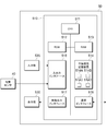
- the automatic welding system 1 shown in FIG. 1 includes a welding robot 10, a robot control device 20, a power supply device 30, a visual sensor 40, and a data processing device 50.
- the automatic welding system 1 in the present embodiment has a function of generating a learning model by using the welding information taught by the operator for the image of the welding position and the corresponding image as the teacher data, and an arc using the generated learning model. It has a function to automatically control welding. Deep learning is used to generate the learning model.
- the welding robot 10 shown in FIG. 1 is a 6-axis articulated robot, and a welding torch 11 for arc welding is attached to the tip thereof.
- the arc welding includes, for example, MIG (Metal InertGas) welding and MAG (Metal Active Gas) welding, and MAG welding is selected in the present embodiment.
- MIG Metal InertGas
- MAG Metal Active Gas
- MAG welding is selected in the present embodiment.
- a portable small robot may be adopted as the welding robot 10.
- the welding wire 13 is supplied to the welding torch 11 from the wire feeding device 12.
- the welding wire 13 is sent out from the tip of the welding torch 11.
- the power supply device 30 is a power supply device and supplies electric power to the welding wire 13. By this electric power, an arc voltage is applied between the welding wire 13 and the work W, and an arc is generated.
- the power supply device 30 is provided with a current sensor (not shown) that detects the welding current flowing from the welding wire 13 during welding to the work W.
- the power supply device 30 has a CPU (Central Processing Unit) and a memory (not shown), and the CPU executes a computer program for power supply control to control the electric power applied to the welding wire 13.
- the power supply device 30 is also connected to the wire feeding device 12, and the CPU controls the feeding speed of the welding wire 13.
- the visual sensor 40 is, for example, a CCD (Charge Coupled Device) camera.
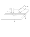
- FIG. 2 is a perspective view illustrating an arrangement position of the visual sensor 40.
- the work W is a butt joint.
- the work W is two metal plates, which are butted with a groove.
- a ceramic backing material 14 is attached to the back surface side of the two metal plates that are butted against each other.
- a metal backing material may be used on the back surface side, or no backing material may be used.
- arc welding is performed in one direction along the groove. In the following, the direction in which welding proceeds is referred to as "forward". In FIG. 2, the direction in which welding proceeds is indicated by an arrow. Therefore, the welding torch 11 is located behind the visual sensor 40.
- the side on which the right hand is located when looking backward from the visual sensor 40 is referred to as "right side”
- the side on which the left hand is located when looking forward is referred to as "left side”.
- the work W in the present embodiment is horizontally installed so that the surface on the side to be welded faces vertically upward. Therefore, the welding robot 10 welds the work W from above the work W.
- the visual sensor 40 is installed obliquely upward with respect to the welding position of the work W.
- the imaging range of the visual sensor 40 includes the welding position of the work W, and captures an image of the welding position during arc welding. This image includes a molten pool, a welding wire 13, and an arc.
- the visual sensor 40 in the present embodiment can continuously capture, for example, a still image of 1024 ⁇ 768 pixels. In other words, the visual sensor 40 can capture a welded image as a moving image.
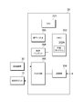
- FIG. 3 is a diagram illustrating a configuration example of a robot control device 20 that controls the operation of the welding robot 10.
- the robot control device 20 includes a CPU 201 that controls the entire device, a memory 202 that stores data, an operation panel 203 that includes a plurality of switches, a teaching pendant 204 that is used in teaching work, an input / output unit 205, and a communication unit. It has 206 and.
- the control program 202A used for controlling the welding robot 10 is stored in the memory 202.
- the CPU 201 controls the welding operation by the welding robot 10 through the execution of the control program 202A.
- An operation panel 203 and a teaching pendant 204 are used for inputting instructions to the robot control device 20.
- the operator can input the teaching program using the teaching pendant 204.
- the robot control device 20 controls the welding operation of the welding robot 10 according to the teaching program input from the teaching pendant 204.
- the teaching program can also be created using a computer (not shown).
- the power supply device 30 and the drive circuit of the welding robot 10 are connected to the input / output unit 205. From the power supply device 30, for example, the current value of the welding current detected by a current sensor (not shown) is given to the CPU 201 through the input / output unit 205. Further, the CPU 201 outputs a control signal based on the control program 202A to the drive circuit of the welding robot 10.
- the communication unit 206 is a communication module for wired or wireless communication. The communication unit 206 is used for data communication with the power supply device 30 and the data processing device 50.
- the robot control device 20 also controls the speed of the welding torch 11 by controlling each axis of the welding robot 10.
- the robot control device 20 controls the speed of the welding torch 11 using the result of image recognition.
- the speed of the welding torch 11 may be controlled to be constant.
- the robot control device 20 also controls the weaving operation of the welding robot 10.
- the weaving operation means that the welding torch 11 is alternately swung in a direction intersecting the welding traveling direction.
- the robot control device 20 controls the weaving operation according to the set period, amplitude, and welding speed.
- the robot control device 20 executes welding line tracing control together with the weaving operation.
- the welding line copying control is an operation of controlling the left and right positions of the welding torch 11 so that a bead is formed along the welding line.
- FIG. 4 is a diagram illustrating a configuration example of the data processing device 50.
- the data processing device 50 is composed of, for example, a computer.
- the computer includes a main body 510, an input unit 520, and a display unit 530.
- the main body 510 includes a CPU 511, a ROM (Read Only Memory) 512, a RAM (Random Access Memory) 513, a non-volatile storage device 514, an input / output interface 515, a communication interface 516, and a video output interface 517.
- the CPU 511, ROM 512, RAM 513, non-volatile storage device 514, input / output interface 515, communication interface 516, and video output interface 517 are connected to each other by a bus or a signal line.
- the non-volatile storage device 514 is generated through the execution of a learning program 514A that executes deep learning using image data obtained by imaging a welding phenomenon and welding information taught by the operator for the image data as teacher data, and a learning program 514A.
- the learning model 514B, the welding information generation program 514C that generates welding information related to arc welding using the learning model 514B, and the image data 514D of the welding position are stored.
- the learning model 514B in the present embodiment is composed of a convolutional neural network.
- an operating system and application programs are also installed in the non-volatile storage device 514.
- the data processing device 50 By executing the program by the CPU 511, the data processing device 50 realizes various functions. In the case of the present embodiment, the data processing device 50 realizes a function of generating a learning model and a function of inputting image data and outputting welding information at the time of actual welding execution. The contents of this function will be described later.
- the data processing device 50 may be separated according to the function of generating a learning model and the function of inputting image data and outputting welding information at the time of actual welding. From the viewpoint of versatility, it is preferable to divide the data processing device 50 according to each function.
- the ROM 512 stores a BIOS (Basic Input Output System) or the like executed by the CPU 511.
- BIOS Basic Input Output System
- the RAM 513 is used as a work area for the program read from the non-volatile storage device 514.
- the input / output interface 515 is connected to an input unit 520 composed of a keyboard, a mouse, and the like.
- a visual sensor 40 is also connected to the input / output interface 515.
- the image data output from the visual sensor 40 is given to the CPU 511 via the input / output interface 515.
- the communication interface 516 is a communication module for wired or wireless communication.
- the video output interface 517 is connected to a display unit 530 composed of, for example, a liquid crystal display or an organic EL (Electro-Luminescence) display, and outputs a video signal corresponding to the video data given by the CPU 511 to the display unit 530. ..
- the learning model 514B is generated by executing the learning program 514A.
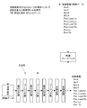
- FIG. 5 is a diagram conceptually explaining the generation process of the learning model 514B.
- the learning model 514B in the present embodiment is configured by a convolutional neural network, and includes a plurality of convolutional layers, a plurality of pooling layers, and a plurality of fully connected layers.
- the learning model 514B takes the image data output from the visual sensor 40 as input, and outputs various welding information appearing in the image data.
- the image data input to the training model 514B includes a molten pool, a welding wire 13 (see FIG. 1), and an arc.
- this image data is referred to as a "welding image”.
- welding is performed with different welding condition settings, and a welding image of each welding state is prepared.
- the welding conditions in the present embodiment include, for example, the protrusion length of the welding wire 13, the brightness (F value) of the image data, the shape of the work W, the shape of the contact tip, the welding current, the arc voltage, the welding speed, the weaving condition, and the like.
- the shape of the contact tip includes a straight nozzle and a tapered nozzle.
- the information defining the welding posture includes, for example, a receding angle, an advancing angle, and a deviation of the welding line with respect to the groove.
- a plurality of weldings in which the setting of "protruding length" is changed among the welding conditions are performed, and a welding image in which the state at the time of each welding is imaged is prepared as teacher data.
- a welding image when the protrusion length is 22 mm a welding image when the protrusion length is 27 mm, and a welding image when the protrusion length is 32 mm are prepared.
- welding information taught by the operator for these welding images is prepared as teacher data. It should be noted that welding may be performed by changing the setting for welding conditions other than the protrusion length, and a welding image of each welding state and welding information taught by the operator for the welding image may be prepared.
- the tip of the welding wire 13 (wire tip), the center point of the arc (arc center), the positions of the left and right tips of the molten pool, and the positions of the left and right ends of the molten pool are used. ..
- Welding information used as teacher data is input by the operator designating a specific position on the welding image according to the instructions on the operation screen that supports the teaching work.
- FIG. 6 is a diagram illustrating an example of a screen used for teaching work.
- the welding image shown in FIG. 6 includes a molten pool 15, a welding wire 13, and an arc 16. In FIG. 6, the molten pool 15 is shaded.
- the welding information includes the coordinate position of the arc center (ArcX, ArcY), the coordinate position of the wire tip (WireX, WireY), the coordinate position of the left end of the molten pool tip (Pool_Lead_Lx, Pool_Lead_Ly), and the right end of the molten pool tip.
- (Pool_Lead_Rx, Pool_Lead_Ry), the coordinate position of the left end of the molten pool (Pool_Lx), and the coordinate position of the right end of the molten pool (Pool_Rx) are taught by the operator.
- Welding information is input by the operator instructing a specific position on the screen.
- the coordinates that give the boundary between the welding wire 13 and the arc are examples of the position coordinates of the wire tip.
- the left end of the tip of the molten pool, the right end of the tip of the molten pool, the left end of the molten pool, and the right end of the molten pool are examples of information on the behavior of the molten pool 15. If the left end of the molten pool and the right end of the molten pool are known, the width of the molten pool 15 can be calculated.
- FIG. 7 is a flowchart illustrating supervised learning of the learning model 514B.
- the symbol S shown in the figure means a step.
- the CPU 511 (see FIG. 4) of the data processing device 50 (see FIG. 1) teaches the image data obtained by imaging the welding performed by changing the settings for at least one of the welding conditions and the image data.
- the welded information is accepted as teacher data (step 1).
- the welding information is prepared in advance by the operator.
- the welding image as the teacher data for example, a shading image whose size is reduced to 120 ⁇ 100 pixels is used.
- the CPU 511 inputs a shade image as teacher data into the learning model 514B, and executes supervised learning so that the output welding information matches the welding information as teacher data (step 2). Specifically, backpropagation processing or the like is executed as error feedback, and the parameters of each layer and layer of the learning model 514B are adjusted.
- the CPU 511 determines whether or not the termination condition is satisfied (step 3).
- the end condition means that, for example, the error average in the latest predetermined number of teacher data is less than a predetermined value. If the end condition is not satisfied (negative result in step 3), the CPU 511 returns to step 2 and continues supervised learning. On the other hand, when the end condition is satisfied (affirmative result in step 3), the CPU 511 ends the generation of the learning model 514B.
- the welding operation of the automatic welding system 1 at the time of actual welding will be described.
- the operator activates each of the robot control device 20, the power supply device 30, and the data processing device 50.
- the robot control device 20 controls the movement of the welding robot 10, and the power supply device 30 executes welding.
- the data processing device 50 monitors the welding image captured by the visual sensor 40 and sequentially calculates welding information related to arc welding.
- the welding information is the position of the wire tip, the arc center, the right end and left end positions of the molten pool tip, and the right end and left end positions of the molten pool.
- FIG. 8 is a flowchart illustrating the processing operation of the robot control device 20 and the power supply device 30.
- the symbol S shown in the figure means a step.
- the operator operates the teaching pendant 204 (see FIG. 3) to input the teaching program, various set values, and the welding start instruction to the robot control device 20.
- the teaching program here defines the movement and the like of the welding robot 10 (see FIG. 1).
- the CPU 201 (see FIG. 3) of the robot control device 20 receives a teaching program, various set values, and a welding start instruction (step 11).
- the CPU 201 commands the power supply device 30 to start welding (start supplying welding power) (step 12).
- the power supply device 30 receives this command (step 13), controls the power supply circuit built in the power supply device 30, and starts welding (step 14).
- a welding voltage is applied between the welding wire 13 (see FIG. 1) and the work W (see FIG. 1), and an arc is generated.
- the CPU 201 transmits a control signal to the welding robot 10 and executes welding control (step 15).
- Welding control includes automatic welding control (step 151), weaving operation control (step 152), and welding line tracing control (step 153).
- the CPU 511 automatically moves the welding torch 11 in the welding direction, and transmits a correction signal for controlling at least one of the welding speed, the welding current, or the arc voltage to the power supply device 30, and the power supply device. 30 performs welding according to the correction signal.
- the automatic welding control includes control of the welding speed, and in the present embodiment, only the welding speed is controlled.
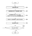
- the CPU 201 determines whether or not it is necessary to stop the welding operation (step 16). When it is not necessary to stop the welding operation (negative result in step 16), the robot control device 20 receives welding information from the data processing device 50 (step 17), and returns to step 15. The CPU 201 returning to step 15 executes welding control based on the received welding information. For example, when a welding stop instruction is received from an operator, a welding end position is detected by a sensor provided in the welding robot 10, a welding abnormality is detected, or both are detected (affirmative result in step 16). The CPU 201 determines that it is necessary to stop the welding operation.
- the CPU 201 stops welding control (step 18) and commands the power supply device 30 to stop welding (step 19). Welding stoppage is realized by stopping the supply of welding power. Further, the CPU 201 instructs the data processing device 50 to stop the generation of welding information (step 20). On the other hand, when the power supply device 30 receives the command to stop welding (step 21), the power supply circuit is controlled by a CPU (not shown) to stop welding (step 22). As a result, the operations of the robot control device 20 and the power supply device 30 are completed.
- FIG. 9 is a flowchart illustrating a process of generating welding information by the data processing device 50, executing welding control based on the welding information, and transmitting a correction signal of each control factor to the power supply device 30.
- Each control factor refers to welding conditions, and examples thereof include welding speed, welding current, arc voltage, weaving operation, and welding line copying.
- the symbol S shown in the figure means a step.
- the CPU 511 of the data processing device 50 receives a welding image of the welding position from the visual sensor 40 while the automatic welding is being executed (step 31). Next, the CPU 511 reduces the received welding image and converts it into a shading image (step 32). The CPU 511 reduces the size of the welded image to 120 ⁇ 100 pixels.
- the CPU 511 inputs the reduced welding image to the learning model 514B, and acquires the welding information output from the learning model 514B (step 33).
- the coordinate position of the arc center (ArcX, ArcY), the coordinate position of the wire tip (WireX, WireY), the coordinate position of the left end of the molten pool tip (Pool_Lead_Lx, Pool_Lead_Ly), and the coordinate position of the right end of the molten pool tip (Pool_Lead_Rx).
- Pool_Lead_Ry) the coordinate position of the left end of the molten pool
- the coordinate position of the right end of the molten pool (Pool_Rx) are output.
- the CPU 511 performs welding control based on the acquired welding information, and calculates a correction signal for each control factor (step 34).
- the left and right position correction amount ⁇ X of the welding torch 11, the speed correction amount ⁇ V of the welding torch 11, and the set value w of the weaving operation width (hereinafter referred to as “weaving width”) are calculated as the correction signals. ..
- the left-right position correction amount ⁇ X of the welding torch 11 is calculated by the following equation (1).
- X0 is a reference value of the position in the left-right direction of the center of the molten pool, and is a preset value.
- the calculated left-right position correction amount ⁇ X is used to move the welding torch 11 in the left-right direction so that the center PoolCenX of the molten pool image coincides with X0.
- the distance ⁇ L is calculated by the following equation (2).
- L0 is the distance between the tip position of the molten pool and the center of the arc, and is preset to a value capable of forming the back wave bead with the highest quality.
- LeadY is also the distance between the tip position of the molten pool and the center of the arc.
- LeadY is calculated by the previous equation (2) using Pool_Lead_Ly, Pool_Lead_Ry and ArcY, which are image feature information extracted from the welded image.
- the distance ⁇ L is the difference between LeadY and L0.
- the speed correction amount ⁇ V is calculated by the following equation (3) using the conversion coefficient ⁇ .
- ⁇ V ⁇ L ⁇ ⁇ (3)
- the weaving width set value w is calculated by the following equation (5) or (6).
- w0 is the gap width of the groove, and is preset to the minimum value that requires weaving.
- Leadw also indicates the gap width, which is a value calculated as described above because the coordinate positions (Pool_Lead_Lx, Pool_Lead_Rx) of the image feature information extracted from the welded image correspond to the left and right positions of the groove. Is. From the above equation (4), when the gap width Leadw is less than w0, the weaving width setting value w becomes 0, and the weaving operation is not performed. From the above equation (5), when the gap width Leadw is w0 or more, the set value w of the weaving width is set to a value smaller than the gap width Leadw by ⁇ . Note that ⁇ is a preset value.
- the process of step 34 may be separately made into a learning model.
- a learning model is generated by using information associating welding information and welding result information as teacher data, and welding information is input to this learning model to be optimal.
- the correction signal of each control factor may be output so as to obtain the welding result.
- the welding result information includes waveform data of welding current, waveform data of arc voltage, arc sound data at the time of welding, bead shape data, spatter generation data, fume generation data, welding defect data, and the like. It is preferable to handle at least one as welding result information.
- the CPU 511 transmits the correction signal to the robot control device 20 (step 35).
- the CPU 511 determines whether or not a stop command for generating a correction signal has been received from the robot control device 20 (step 36). If the stop command has not been received (negative result in step 36), the CPU 511 returns to step 31. On the other hand, when the stop command is received (affirmative result in step 36), the CPU 511 ends the correction signal generation process.
- the welding image captured by changing the setting for at least one of the welding conditions and the welding information taught by the operator for the welding image are used as the teacher data. Since deep learning is executed to generate the learning model 514B, highly reliable welding information can be stably output regardless of various welding conditions set in actual welding. That is, a learning model that is robust is generated.
- FIG. 10 is a diagram illustrating an example of welding conditions used for generating teacher data.
- the teacher data corresponding to the method described in the embodiment is referred to as a specific example 1
- the teacher data corresponding to the conventional method is referred to as a comparative example 1.
- a total of 5400 welding images are used as teacher data. This number is twice the number of welded images used in Comparative Example 1.
- the welding image of Specific Example 1 is different from the welding image of Comparative Example 1 in the following two points.
- the first difference is that two types of settings are used for the protrusion length, which is one of the welding conditions. In the case of Comparative Example 1, only the welding image captured in the state of the protrusion length of 25 mm is obtained, but in the case of Specific Example 1, the welding image captured in the state of 22 mm is added.
- the second difference is that the welding image is added when the welding wire 13 (see FIG. 1) is located on the right side and the left side of the molten pool.
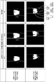
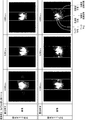
- FIG. 11 is a diagram illustrating an output example of welding information corresponding to Specific Example 1 and an output example of welding information corresponding to Comparative Example 1.
- FIG. 11 shows six welded images. The upper three welding images correspond to the state where the welding wire 13 is located to the right of the molten pool, and the lower three welding images correspond to the state where the welding wire 13 is located to the left of the molten pool. Further, the welding image in the two rows on the left side corresponds to Comparative Example 1, and the welding image in the one row on the right side corresponds to Specific Example 1.
- FIG. 12 is a diagram illustrating another example of welding conditions used for generating teacher data.
- the teacher data corresponding to the method described in the embodiment is referred to as a specific example 2
- the teacher data corresponding to the conventional method is referred to as a comparative example 2.
- some of the corresponding welding conditions are different from the welding image of Specific Example 1.
- the welding images when the welding wire 13 (see FIG. 1) is located on the right side and the left side of the molten pool are used as teacher data, but the exposure time and groove gap, which are the welding conditions, are used. Also considers multiple settings.
- the exposure time of Comparative Example 2 is one type of 1,100 ⁇ s, but the exposure time of Specific Example 2 is three types of 2,000 ⁇ s, 1,100 ⁇ s, and 800 ⁇ s.
- the groove gap of Comparative Example 2 is only 5 mm, but the groove gap of Specific Example 2 considers 100 patterns in the range of 3 to 10 mm. The value of the groove gap is randomly determined.
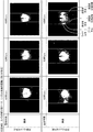
- FIG. 13 shows six welded images.
- the upper three weld images are for a narrow groove gap, and the lower three weld images are for a wider groove gap.
- the leftmost column is for an exposure time of 2,000 ⁇ s, the middle column is for an exposure time of 1,100 ⁇ s, and the rightmost column is for an exposure time of 800 ⁇ s.
- the positions of the arc center, the wire tip, the left end of the molten pool tip, the right end of the molten pool tip, the left end of the molten pool, and the right end of the molten pool are correctly recognized.
- FIG. 13 shows six welded images.
- the upper three weld images are for a narrow groove gap, and the lower three weld images are for a wider groove gap.
- the leftmost column is for an exposure time of 2,000 ⁇ s
- the middle column is for an exposure time of 1,100
- the leftmost column has an exposure time of 6,000 ⁇ s
- the middle column has an exposure time of 5,000 ⁇ s
- the rightmost column has an exposure time of 4,000 ⁇ s.
- both the exposure time and the aperture value F of the camera are different from the setting of the welding conditions used for learning the learning model 514B.
- any of the welding information is accurately recognized.
- a reference numeral corresponding to a portion corresponding to that in FIG. 13 is added. That is, the upper three weld images are for the case where the groove gap is narrow, and the lower three weld images are for the case where the groove gap is wide.
- the leftmost column is for an exposure time of 2,000 ⁇ s, the middle column is for an exposure time of 1,100 ⁇ s, and the rightmost column is for an exposure time of 800 ⁇ s.
- a reference numeral corresponding to a portion corresponding to that in FIG. 14 is added. That is, the three welded images in the upper row are cases where the groove gap is narrow, and the three welded images in the lower row are cases where the groove gap is wide.
- the leftmost column is for an exposure time of 6,000 ⁇ s
- the middle column is for an exposure time of 5,000 ⁇ s
- the rightmost column is for an exposure time of 4,000 ⁇ s. Also in the case of FIG.
- a deviation is observed in any of the positions of the arc center, the wire tip, the left end of the molten pool tip, the right end of the molten pool tip, the left end of the molten pool, and the right end of the molten pool.
- the recognition accuracy is greatly reduced.
- one welding image corresponding to a plurality of settings of at least one welding condition is prepared as the teacher data used for learning the learning model 514B.
- the influence of the change of the exposure condition in the usage environment on the recognition accuracy of the welding information is reduced.
- the control of welding using the recognition result becomes appropriate, and the quality is improved by automatic welding.
- the welding robot 10 has described an example of an articulated robot, but a single-joint robot may also be used.
- the left end of the molten pool and the right end of the molten pool are output as welding information, but the width of the molten pool calculated based on these information may be output.
- the welding information may include the tip width of the molten pool calculated from the left end of the tip of the molten pool and the right end of the tip of the molten pool.
- the welding information may include L0 and LeadY, which are the distances between the welding pond tip position and the arc center.
- the protrusion length which is the welding condition
- the welding image of the welding state at each protrusion length is used as the teacher data.
- the step size of the protruding length may be 3 mm.
- the step size of the protrusion length used for capturing the welding image used as the teacher data is arbitrary.
- the learning model 514B may be generated by using the welding image captured by varying the respective settings for any one or more of the above-mentioned welding conditions as the teacher data.
Landscapes
- Engineering & Computer Science (AREA)
- Physics & Mathematics (AREA)
- Mechanical Engineering (AREA)
- Theoretical Computer Science (AREA)
- Robotics (AREA)
- Plasma & Fusion (AREA)
- Software Systems (AREA)
- Computing Systems (AREA)
- Mathematical Physics (AREA)
- Artificial Intelligence (AREA)
- General Physics & Mathematics (AREA)
- Data Mining & Analysis (AREA)
- Evolutionary Computation (AREA)
- General Engineering & Computer Science (AREA)
- Biomedical Technology (AREA)
- Biophysics (AREA)
- Molecular Biology (AREA)
- General Health & Medical Sciences (AREA)
- Computational Linguistics (AREA)
- Health & Medical Sciences (AREA)
- Life Sciences & Earth Sciences (AREA)
- Automation & Control Theory (AREA)
- Human Computer Interaction (AREA)
- Multimedia (AREA)
- Image Analysis (AREA)
- Manipulator (AREA)
- Medical Informatics (AREA)
- Computer Vision & Pattern Recognition (AREA)
- Arc Welding Control (AREA)
Abstract
Description
ところで、溶接現象は、溶接電流、アーク電圧、チップ-母材間距離(以下「突出し長さ」ともいう)、被溶接物(以下「ワーク」ともいう)の形状、溶接姿勢、視覚センサの位置その他のアーク溶接条件(以下「溶接条件」という)の組み合わせの違いにより種々変化する。
しかるに、特許文献1では、個々の溶接条件の設定の違いが溶接現象に与える影響が言及されていない。
このため、特許文献1の場合には、学習モデルの学習に用いた溶接条件の設定と、現実の溶接で使用する溶接条件の設定が異なる場合、溶接現象から自動的に抽出される物理量(以下「溶接情報」ともいう)の精度が安定せず、誤って抽出された溶接情報に基づいて誤った処理が実行される可能性がある。
また、少なくとも1つの溶接条件は、溶接ワイヤの突出し長さであり、突出し長さの設定は、少なくとも10~40mmの範囲の中から複数選択されることが好ましい。
また、溶融池の挙動に関する情報は、溶接が進行する方向に出現する溶融池の先端の1つ以上の位置の情報、及び、溶接が進行する方向に対して溶融池の左右の端部の位置の情報が含まれることが好ましい。
また、溶接ワイヤの位置に関する情報は、溶接ワイヤの先端位置の情報が含まれることが好ましい。
また、アークに関する情報は、アークの中心点の情報を含むことが好ましい。
図1は、実施の形態の説明に使用する自動溶接システム1の構成例を示す図である。
図1に示す自動溶接システム1は、溶接ロボット10と、ロボット制御装置20と、電源装置30と、視覚センサ40と、データ処理装置50を備えている。
本実施の形態における自動溶接システム1は、溶接位置の画像と対応する画像についてオペレータが教示した溶接情報とを教師データに用いて学習モデルを生成する機能と、生成された学習モデルを用いてアーク溶接を自動制御する機能とを有している。なお、学習モデルの生成には、ディープラーニングを使用する。
また、溶接ロボット10は例えば可搬型の小型ロボットを採用しても良い。
電源装置30は電源装置であり、溶接ワイヤ13に電力を供給する。この電力により、溶接ワイヤ13とワークWとの間にはアーク電圧が印加され、アークが発生する。電源装置30には、溶接中の溶接ワイヤ13からワークWに流れる溶接電流を検出する不図示の電流センサが設けられている。
電源装置30は、ワイヤ送給装置12にも接続され、CPUが、溶接ワイヤ13の送給速度を制御する。
図2は、視覚センサ40の配置位置を説明する斜視図である。本実施の形態の場合、ワークWは、突合せ継手である。ワークWは、2枚の金属板であり、開先を隔てて突き合わされている。なお、突き合わされている2枚の金属板の裏面側には、セラミックス製の裏当て材14が取り付けられている。なお、裏面側にはメタル系の裏当て材を使用してもよいし、裏当て材無しでもよい。
突合せ継手では、開先に沿って一方向にアーク溶接が行われる。
以下では、溶接が進行する方向を「前方」という。図2では、溶接が進行する方向を矢印で示している。このため、溶接トーチ11は、視覚センサ40の後方に位置している。
また、本実施の形態では、視覚センサ40から後方を見る場合に右手が位置する側を「右方」、前方を見る場合に左手が位置する側を「左方」という。
図2に示すように、視覚センサ40は、ワークWの溶接位置に対して斜め上方に設置される。視覚センサ40の撮像範囲は、ワークWの溶接位置を含み、アーク溶接中における溶接位置の画像を撮像する。この画像には、溶融池と、溶接ワイヤ13と、アークが含まれる。
本実施の形態における視覚センサ40は、例えば1024×768ピクセルの静止画像を連続して撮像することができる。換言すると、視覚センサ40は、溶接画像を動画像として撮像することが可能である。
図3は、溶接ロボット10の動作を制御するロボット制御装置20の構成例を説明する図である。
ロボット制御装置20は、装置全体を制御するCPU201と、データを記憶するメモリ202と、複数のスイッチを含む操作パネル203と、教示作業で使用する教示ペンダント204と、入出力部205と、通信部206とを有している。
メモリ202には、溶接ロボット10の制御に用いられる制御プログラム202Aが記憶されている。CPU201は、制御プログラム202Aの実行を通じ、溶接ロボット10による溶接動作を制御する。
ロボット制御装置20は、教示ペンダント204から入力された教示プログラムに従って溶接ロボット10の溶接動作を制御する。もっとも、教示プログラムは、不図示のコンピュータを用いて作成することも可能である。
通信部206は、有線又は無線通信用の通信モジュールである。通信部206は、電源装置30及びデータ処理装置50とのデータ通信に使用される。
ロボット制御装置20は、ウィービング動作と共に、溶接線倣い制御を実行する。溶接線倣い制御とは、溶接線に沿ってビードが形成されるように、溶接トーチ11の左右の位置を制御する動作である。
図4は、データ処理装置50の構成例を説明する図である。
データ処理装置50は、例えばコンピュータで構成される。コンピュータは、本体510と、入力部520と、表示部530とを備えている。
本体510は、CPU511と、ROM(Read Only Memory)512と、RAM(Random Access Memory)513と、不揮発性記憶装置514と、入出力インタフェース515と、通信インタフェース516と、映像出力インタフェース517を有している。
CPU511、ROM512、RAM513、不揮発性記憶装置514、入出力インタフェース515、通信インタフェース516、映像出力インタフェース517は、バスや信号線によって相互に接続されている。
本実施の形態における学習モデル514Bは、畳み込みニューラルネットワーク(Convolutional Neural Network)で構成される。この他、不揮発性記憶装置514には、オペレーティングシステムやアプリケーションプログラムもインストールされている。
本実施の形態の場合、データ処理装置50は、学習モデルを生成する機能と、実際の溶接の実行時に画像データを入力し、溶接情報を出力する機能を実現する。これの機能の内容については後述する。なお、学習モデルを生成する機能と、実際の溶接の実行時に画像データを入力し、溶接情報を出力する機能に合わせてデータ処理装置50を分けてもよい。汎用性の観点から見ると、それぞれの機能に合わせて、データ処理装置50を分けることが好ましい。
ROM512には、CPU511に実行されるBIOS(Basic Input Output System)等が記憶されている。RAM513は、不揮発性記憶装置514から読み出されたプログラムの作業領域として使用される。
通信インタフェース516は、有線又は無線通信用の通信モジュールである。映像出力インタフェース517は、例えば液晶ディスプレイや有機EL(Electro-Luminescence)ディスプレイで構成される表示部530に接続されており、CPU511から与えられた映像データに応じた映像信号を表示部530に出力する。
以下では、自動溶接システム1の動作を説明する。
ここでは、学習モデル514Bの生成について説明する。学習モデル514Bは、学習プログラム514Aの実行により生成される。
図5は、学習モデル514Bの生成プロセスを概念的に説明する図である。本実施の形態における学習モデル514Bは、畳み込みニューラルネットワークにより構成されており、複数の畳み込み層と、複数のプーリング層と、複数の全結合層とを含んでいる。
学習モデル514Bに入力される画像データには、溶融池、溶接ワイヤ13(図1参照)及びアークが含まれる。以下、この画像データを「溶接画像」という。
本実施の形態の場合、溶接条件の設定を変えた溶接を行い、各溶接の様子を撮像した溶接画像を用意する。
本実施の形態における溶接条件には、例えば溶接ワイヤ13の突出し長さ、画像データの明度(F値)、ワークWの形状、コンタクトチップの形状、溶接電流、アーク電圧、溶接速度、ウィービング条件、ワークWに対する溶接ワイヤ13の姿勢(溶接姿勢)がある。
例えばコンタクトチップの形状には、ストレートノズルとテーパーノズルがある。また、溶接姿勢を規定する情報には、例えば後退角、前進角、開先に対する溶接線のズレがある。
なお、突出し長さ以外の溶接条件についても設定を変えて溶接を行い、各溶接時の様子を撮像した溶接画像とその溶接画像についてオペレータが教示した溶接情報を用意してもよい。
教師データとして用いる溶接情報の入力は、教示作業を支援する操作画面の指示に従い、オペレータが溶接画像上の特定の位置を指定することで行われる。
図6は、教示作業に用いる画面の一例を説明する図である。図6に示す溶接画像には、溶融池15、溶接ワイヤ13、アーク16が含まれている。図6では、溶融池15を網掛けで示す。
溶接情報の入力は、画面上の特定の位置をオペレータが指示することで実行される。
溶接ワイヤ13とアークの境界を与える座標は、ワイヤ先端の位置座標の一例である。
また、溶融池先端左端と、溶融池先端右端と、溶融池左端と、溶融池右端は、溶融池15の挙動に関する情報の一例である。なお、溶融池左端と溶融池右端が分かると、溶融池15の幅を計算できる。
教師あり学習の実行時、データ処理装置50(図1参照)のCPU511(図4参照)は、溶接条件の少なくとも1つについて設定を変えて行った溶接を撮像した画像データとその画像データについて教示された溶接情報を教師データとして受け付ける(ステップ1)。
前述したように、溶接情報は、オペレータにより事前に用意される。本実施の形態の場合、教師データとしての溶接画像には、例えば120×100ピクセルにサイズが縮小された濃淡画像を使用する。
次に、CPU511は、終了条件を満足するか否かを判定する(ステップ3)。終了条件とは、例えば直近所定個の教師データにおける誤差平均が所定値未満であることをいう。
終了条件を満足しない場合(ステップ3で否定結果)、CPU511は、ステップ2に戻り、教師あり学習を継続する。一方、終了条件を満足する場合(ステップ3で肯定結果)、CPU511は、学習モデル514Bの生成を終了する。
以下、実際の溶接時における自動溶接システム1の溶接動作について説明する。
アーク溶接を行う場合、オペレータは、ロボット制御装置20、電源装置30及びデータ処理装置50のそれぞれを起動する。
ロボット制御装置20が溶接ロボット10の動きを制御し、電源装置30が溶接を実行する。また、データ処理装置50は、視覚センサ40により撮像される溶接画像を監視し、アーク溶接に関する溶接情報を逐次算出する。
本実施の形態では、溶接情報を、ワイヤ先端の位置、アーク中心、溶融池先端右端および左端位置、および、溶融池右端および左端位置とする。
オペレータは、アーク溶接を開始する場合、教示ペンダント204(図3参照)を操作して、ロボット制御装置20に対して教示プログラム、各種設定値及び溶接開始指示を入力する。ここでの教示プログラムは、溶接ロボット10(図1参照)の動き等を規定する。
ロボット制御装置20のCPU201(図3参照)は、教示プログラム、各種設定値及び溶接開始指示を受け付ける(ステップ11)。
次にCPU201は、溶接ロボット10に制御信号を送信し、溶接制御を実行する(ステップ15)。溶接制御は、自動溶接制御(ステップ151)、ウィービング動作の制御(ステップ152)及び溶接線倣い制御(ステップ153)を含む。
自動溶接制御では、CPU511が自動的に溶接方向に溶接トーチ11を移動させながら、溶接速度、溶接電流又はアーク電圧の少なくとも一つを制御するための補正信号を電源装置30に送信し、電源装置30が補正信号にしたがい溶接を実行する。なお、制御の容易性の観点から自動溶接制御において、溶接速度の制御を含むことが好ましく、本実施形態では溶接速度の制御のみを行っている。
例えばオペレータからの溶接停止の指示の受け付け、溶接ロボット10に設けられたセンサによる溶接終了位置の検出、又は、溶接異常の検出、又は、両方の検出があった場合(ステップ16で肯定結果)、CPU201は、溶接動作の停止が必要と判断する。
また、CPU201は、データ処理装置50に対して溶接情報の生成停止を指令する(ステップ20)。
一方、電源装置30は、溶接停止の指令を受信すると(ステップ21)、不図示のCPUにより電源回路を制御して溶接を停止する(ステップ22)。これにより、ロボット制御装置20及び電源装置30の動作が終了する。
図9は、データ処理装置50による溶接情報の生成処理と、溶接情報に基づいて溶接制御を実行し、各制御因子の補正信号を電源装置30に送信するまでを説明するフローチャートである。なお、各制御因子とは、溶接条件を指し、例えば、溶接速度、溶接電流、アーク電圧、ウィービング動作、又は溶接線倣い等が挙げられる。図中に示す記号のSはステップを意味する。
データ処理装置50のCPU511は、自動溶接が実行されている間、視覚センサ40から溶接位置を撮像した溶接画像を受信する(ステップ31)。
次に、CPU511は、受信した溶接画像を縮小し、濃淡画像に変換する(ステップ32)。なお、CPU511は、溶接画像のサイズを120×100ピクセルに縮小する。
学習モデル514Bからは、アーク中心の座標位置(ArcX,ArcY)、ワイヤ先端の座標位置(WireX,WireY)、溶融池先端左端の座標位置(Pool_Lead_Lx,Pool_Lead_Ly)、溶融池先端右端の座標位置(Pool_Lead_Rx,Pool_Lead_Ry)、溶融池左端の座標位置(Pool_Lx)、溶融池右端の座標位置(Pool_Rx)が出力される。
本実施の形態の場合、補正信号として、溶接トーチ11の左右位置補正量ΔX、溶接トーチ11の速度補正量ΔV、ウィービング動作の幅(以下「ウィービング幅」という)の設定値wが算出される。
溶接トーチ11の左右位置補正量ΔXは、次式(1)により算出される。
PoolCenX=(Pool_Lx+Pool_Rx)/2
ΔX=PoolCenX-X0 (1)
ただし、X0は溶融池の中心の左右方向位置の基準値であり、予め設定された値である。
算出された左右位置補正量ΔXは、溶融池像の中心PoolCenXがX0に一致させるように溶接トーチ11を左右方向に移動させるために用いられる。
LeadY=(Pool_Lead_Ly+Pool_Lead_Ry)/2-ArcY
ΔL=LeadY-L0 (2)
ただし、L0は、溶融池先端位置とアーク中心の距離であり、最も品質がよい裏波ビードを形成できる値に予め設定される。
LeadYも溶融池先端位置とアーク中心の距離である。ただし、LeadYは、溶接画像から抽出される画像特徴情報であるPool_Lead_Ly、Pool_Lead_Ry及びArcYを用いる前式(2)により算出される。
距離ΔLは、LeadYとL0との差分である。距離ΔLが算出されると、変換係数βを用いる次式(3)により速度補正量ΔVが算出される。
ΔV=ΔL×β (3)
Leadw=Pool_Lead_Rx-Pool_Lead_Lx
IF Leadw < w0 THEN w=0 (4)
IF Leadw ≧ w0 THEN w=(Leadw-α) (5)
ただし、w0は開先のギャップ幅であり、ウィービングが必要となる最低限の値に予め設定される。
上記の(4)式より、ギャップ幅Leadwがw0未満である場合、ウィービング幅の設定値wは0となり、ウィービング動作は行われない。
上記の(5)式より、ギャップ幅Leadwがw0以上である場合、ウィービング幅の設定値wはギャップ幅Leadwよりαだけ小さい値とされる。なお、αは予め設定される値である。
次にCPU511は、ロボット制御装置20から補正信号の生成の停止指令を受信したか否かを判定する(ステップ36)。
停止司令を受信していない場合(ステップ36で否定結果)、CPU511は、ステップ31へ戻る。
一方、停止指令を受信した場合(ステップ36で肯定結果)、CPU511は、補正信号の生成処理を終了する。
以下では、実施の形態で説明した手法で生成された学習モデル514Bを用いることにより溶接情報の認識精度が向上することを説明する。
(1)具体例1
図10は、教師データの生成に用いる溶接条件の一例を説明する図である。図10においては、実施の形態で説明する手法に対応する教師データを具体例1といい、従前の手法に対応する教師データを比較例1という。
具体例1の場合、教師データとして計5400枚の溶接画像を使用する。この枚数は、比較例1で使用する溶接画像の枚数の2倍である。
相違点の1つ目は、溶接条件の1つである突出し長さについて2種類の設定を用いる点である。比較例1の場合、突出し長さが25mmの状態で撮像された溶接画像だけであるが、具体例1の場合には、22mmの状態で撮像された溶接画像が追加されている。
相違点の2つ目は、溶接ワイヤ13(図1参照)が溶融池の右側に位置する場合と左側に位置する場合の溶接画像を追加する点である。
もっとも、比較例1の場合、教師データとして用いる溶接画像内における溶接ワイヤ13の位置を特定していないので、溶接ワイヤ13が溶融池の右側に位置する状態で撮像された溶接画像も溶接ワイヤ13が溶融池の左側に位置する状態で撮像された溶接画像も含まれている可能性がある。ただし、該当位置の枚数は、具体例1に比べると格段に少なくなる。
図11には、6つの溶接画像が示されている。上段の3つの溶接画像は溶接ワイヤ13が溶融池の右に位置する状態に対応し、下段の3つの溶接画像は溶接ワイヤ13が溶融池の左に位置する状態に対応する。また、左側の2列の溶接画像は比較例1に対応し、右側の1列の溶接画像は具体例1に対応する。
各溶接画像には、学習モデル514Bを用いて認識された、アーク中心、ワイヤ先端、溶融池先端左端、溶融池先端右端、溶融池左端、溶融池右端の位置が丸印で示されている。
一方、具体例1の場合、いずれの溶接画像でも、ワイヤ先端の認識位置を示す丸印と溶接ワイヤ13の先端とが重なっている。すなわち、具体例1の場合には、正しい位置が認識されている。なお、具体例1の場合には、溶接ワイヤ13が溶融池に対してどの位置にある場合にも、ワイヤ先端の認識の精度の向上が確認されている。
また、比較例1の場合には、学習モデルの生成に使用した突出し長さと実際の溶接環境で用いる突出し長さが異なると、ワイヤ先端の認識精度の低下が確認されたが、具体例の場合には、溶接環境で用いる突出し長さによらず精度の高い認識が可能である。
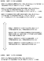
図12は、教師データの生成に用いる溶接条件の他の一例を説明する図である。図12においては、実施の形態で説明する手法に対応する教師データを具体例2といい、従前の手法に対応する教師データを比較例2という。
具体例2の溶接画像は、対応する溶接条件の一部が、具体例1の溶接画像と異なっている。具体例2も、溶接ワイヤ13(図1参照)が溶融池の右側に位置する場合と左側に位置する場合の溶接画像を教師データとして使用するが、溶接条件である露光時間と開先ギャップについても複数の設定を考慮している。
また、比較例2の開先ギャップは5mmのみであるが、具体例2の開先ギャップは3~10mmの範囲の100パターンを考慮している。なお、開先ギャップの値はランダムに決められている。
なお、具体例2で用いる溶接画像と比較例2で用いるカメラの絞り値はいずれもF=8である。
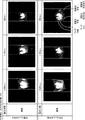
図13には、6つの溶接画像が示されている。上段の3つの溶接画像は開先ギャップが狭めの場合であり、下段の3つの溶接画像は開先ギャップが広めの場合である。また、左端の列は露光時間が2,000μsの場合であり、真ん中の列は露光時間が1,100μsの場合であり、右端の列は露光時間が800μsの場合である。
いずれの溶接画像についても、アーク中心、ワイヤ先端、溶融池先端左端、溶融池先端右端、溶融池左端、溶融池右端の位置が正しく認識されている。
図14は、現実の溶接環境で用いられるカメラの絞り値がF=15の場合における具体例2の出力例を説明する図である。図14の場合、左端の列は露光時間が6,000μsの場合であり、真ん中の列は露光時間が5,000μsの場合であり、右端の列は露光時間が4,000μsの場合である。
図14の場合、露光時間とカメラの絞り値Fのいずれもが、学習モデル514Bの学習に使用した溶接条件の設置とは異なっている。しかし、図14に示すいずれの溶接画像でも、溶接情報のいずれもが正確に認識されている。
比較例2の場合、いずれの溶接画像にも、アーク中心、ワイヤ先端、溶融池先端左端、溶融池先端右端、溶融池左端、溶融池右端の位置のいずれかの認識にずれが認められる。例えば露光時間が2,000μsの場合、開先ギャップの幅に関係無く、認識されたアーク中心やワイヤ先端が正しい位置から大きくずれている。また、溶融池先端右端と左端も同様に正しい位置から大きくずれている。
図16の場合も、アーク中心、ワイヤ先端、溶融池先端左端、溶融池先端右端、溶融池左端、溶融池右端の位置のいずれかの認識にずれが認められる。例えば露光時間が6,000μsで開先ギャップが狭い場合、認識された溶融池先端右端と左端、溶融池右端と左端は正しい位置から大きくずれている。また、露光時間が6,000μsでも開先ギャップが広い場合、認識されたアーク中心とワイヤ先端は正しい位置から大きくずれている。
このように比較例2の場合、現実の溶接環境で用いる溶接条件が学習時に用いた溶接条件と異なる場合に、認識の精度が大きく低下する。
以上2つの具体例を用いて説明したように、学習モデル514Bの学習に用いる教師データとして、少なくとも1つの溶接条件の複数の設定に対応する溶接画像を用意することにより、1つの溶接条件の1つの設定に対応する溶接画像を教師データに用いる場合に比して、使用環境における露光条件の変化が溶接情報の認識精度に与える影響が少なくなる。
その結果、認識の結果を用いる溶接の制御が適正になり、自動溶接による品質の向上が実現される。
以上、本発明の実施の形態について説明したが、本発明の技術的範囲は上述の実施の形態に記載の範囲に限定されない。上述の実施の形態に、種々の変更又は改良を加えたものも、本発明の技術的範囲に含まれることは、特許請求の範囲の記載から明らかである。
(1)例えば前述の実施の形態では、アーク溶接機の一例として溶極式のMIG溶接やMAG溶接を例示したが、不活性ガスの中でアークを発生させるTIG(Tungsten Inert Gas)溶接を用いてもよい。この場合には、溶接条件として溶加材の形状や姿勢の設定を変更した状態で撮像した溶接画像を追加で用意してもよい。また、アークを発生させない溶接機にも適用が可能である。例えばエレクトロスラグ溶接による溶接にも用いてもよい。
(3)前述の実施の形態では、溶融池左端と溶融池右端を溶接情報として出力しているが、これらの情報により計算される溶融池の幅を出力してもよい。また、溶接情報には、溶融池先端左端と溶融池先端右端から計算される溶融池の先端幅を含めてもよい。また、溶接情報には、溶接池先端位置とアーク中心の距離であるL0やLeadYを含めてもよい。
Claims (10)
- 溶接の様子を撮像する視覚センサから出力される画像データが入力されると、当該画像データに対応する溶接情報を出力する学習モデルを生成する学習モデル生成方法であって、
前記学習モデルの生成に使用される前記画像データは、少なくとも1つの溶接条件の複数の設定について撮像され、
前記画像データは、溶融池、溶接ワイヤ、及び、アークの少なくとも1つを含み、
前記溶接情報は、溶融池の挙動に関する情報、溶接ワイヤの位置に関する情報、及び、アークに関する情報の少なくとも1つを含み、
前記画像データと当該画像データに対応する前記溶接情報とを教師データに用いて前記学習モデルを生成する
ことを特徴とする溶接情報の学習モデル生成方法。 - 前記画像データは、前記溶接ワイヤの突出し長さ、ノズルの形状、前記画像データの明度、被溶接物の形状、コンタクトチップの形状、溶接電流、アーク電圧、溶接速度、ウィービング条件、溶接姿勢のうちの少なくとも1つに関する2つ以上の設定に対応する
ことを特徴とする請求項1に記載の溶接情報の学習モデル生成方法。 - 前記少なくとも1つの溶接条件は、前記溶接ワイヤの突出し長さであり、
前記突出し長さの設定は、少なくとも10~40mmの範囲の中から複数選択される
ことを特徴とする請求項2に記載の溶接情報の学習モデル生成方法。 - 前記溶融池の挙動に関する情報は、
溶接が進行する方向に出現する前記溶融池の先端の1つ以上の位置の情報、及び、溶接が進行する方向に対して当該溶融池の左右の端部の位置の情報が含まれる
ことを特徴とする請求項1~3のいずれか1項に記載の溶接情報の学習モデル生成方法。 - 前記溶接ワイヤの位置に関する情報は、
前記溶接ワイヤの先端位置の情報が含まれる
ことを特徴とする請求項1~3のいずれか1項に記載の溶接情報の学習モデル生成方法。 - 前記アークに関する情報は、
前記アークの中心点の情報を含む
ことを特徴とする請求項1~3のいずれか1項に記載の溶接情報の学習モデル生成方法。 - 溶接の様子を撮像する視覚センサから出力される画像データ
が入力されると、当該画像データに対応する溶接情報を出力する学習モデルであり、
前記学習モデルの生成に使用される前記画像データは、少なくとも1つの溶接条件の複数の設定について撮像され、
前記画像データは、溶融池、溶接ワイヤ、及び、アークの少なくとも1つを含み、
前記溶接情報は、溶融池の挙動に関する情報、溶接ワイヤの位置に関する情報、及び、アークに関する情報の少なくとも1つを含み、
前記学習モデルは、前記画像データと当該画像データに対応する前記溶接情報とを教師データに用いて生成される
ことを特徴とする学習モデル。 - 溶接の様子を撮像する視覚センサから出力される画像データが入力されると、当該画像データに対応する溶接情報を出力する学習モデルを生成する機能をコンピュータに実現させるプログラムであり、
前記機能は、前記画像データと当該画像データに対応する前記溶接情報を教師データに使用し、
前記学習モデルの生成に使用される前記画像データは、少なくとも1つの溶接条件の複数の設定について撮像され、
前記画像データは、溶融池、溶接ワイヤ、及び、アークの少なくとも1つを含み、
前記溶接情報は、溶融池の挙動に関する情報、溶接ワイヤの位置に関する情報、及び、アークに関する情報の少なくとも1つを含む、
ことを特徴とするプログラム。 - 被溶接物を溶接する溶接装置と、
溶接の様子を撮像する視覚センサと、
前記視覚センサから出力される画像データが入力されると、当該画像データに対応する溶接情報を出力する学習モデルと、
前記視覚センサで撮像された前記画像データを前記学習モデルに入力した場合に出力される前記溶接情報を用いて、前記溶接装置の動きを制御する制御装置と
を有し、
前記学習モデルの生成に使用される前記画像データは、少なくとも1つの溶接条件の複数の設定について撮像され、
前記画像データは、溶融池、溶接ワイヤ、及び、アークの少なくとも1つを含み、
前記溶接情報は、溶融池の挙動に関する情報、溶接ワイヤの位置に関する情報、及び、アークに関する情報の少なくとも1つを含み、
前記制御装置は、前記画像データと当該画像データに対応する前記溶接情報とを教師データに用いて前記学習モデルを生成する
ことを特徴とする溶接システム。 - 前記画像データに対応する前記溶接情報を出力する前記学習モデルに加え、当該学習モデルから出力された当該溶接情報を入力し、当該溶接情報の補正信号を出力する別の学習モデルを設ける、
ことを特徴とする請求項9に記載の溶接システム。
Priority Applications (4)
| Application Number | Priority Date | Filing Date | Title |
|---|---|---|---|
| CN202180016221.6A CN115151365B (zh) | 2020-04-30 | 2021-03-29 | 焊接信息的学习模型生成方法、学习模型、程序产品以及焊接系统 |
| US17/996,042 US20230241703A1 (en) | 2020-04-30 | 2021-03-29 | Welding-information learning-model generation method, learning model, program, and welding system |
| KR1020227036894A KR102809291B1 (ko) | 2020-04-30 | 2021-03-29 | 용접 정보의 학습 모델 생성 방법, 학습 모델, 프로그램 및 용접 시스템 |
| EP21797557.2A EP4063056A4 (en) | 2020-04-30 | 2021-03-29 | LEARNING MODEL GENERATION METHOD, LEARNING MODEL AND PROGRAM FOR WELDING INFORMATION, AND WELDING SYSTEM |
Applications Claiming Priority (2)
| Application Number | Priority Date | Filing Date | Title |
|---|---|---|---|
| JP2020080006A JP7551327B2 (ja) | 2020-04-30 | 2020-04-30 | 溶接情報の学習モデル生成方法、学習モデル、プログラム及び溶接システム |
| JP2020-080006 | 2020-04-30 |
Publications (1)
| Publication Number | Publication Date |
|---|---|
| WO2021220698A1 true WO2021220698A1 (ja) | 2021-11-04 |
Family
ID=78281070
Family Applications (1)
| Application Number | Title | Priority Date | Filing Date |
|---|---|---|---|
| PCT/JP2021/013400 Ceased WO2021220698A1 (ja) | 2020-04-30 | 2021-03-29 | 溶接情報の学習モデル生成方法、学習モデル、プログラム及び溶接システム |
Country Status (6)
| Country | Link |
|---|---|
| US (1) | US20230241703A1 (ja) |
| EP (1) | EP4063056A4 (ja) |
| JP (1) | JP7551327B2 (ja) |
| KR (1) | KR102809291B1 (ja) |
| CN (1) | CN115151365B (ja) |
| WO (1) | WO2021220698A1 (ja) |
Cited By (3)
| Publication number | Priority date | Publication date | Assignee | Title |
|---|---|---|---|---|
| KR20230091245A (ko) * | 2021-12-15 | 2023-06-23 | (주)글로벌엔지니어링 | 딥 러닝 알고리즘을 이용한 고정자 코일의 레이저 용접 시스템 |
| WO2024157608A1 (ja) * | 2023-01-23 | 2024-08-02 | 株式会社神戸製鋼所 | ウィービング制御方法、溶接制御装置、溶接システム、プログラムおよび溶接方法 |
| EP4534235A4 (en) * | 2022-08-18 | 2025-10-08 | Mitsubishi Heavy Ind Ltd | WELDING DATA COLLECTION PROCESS |
Families Citing this family (8)
| Publication number | Priority date | Publication date | Assignee | Title |
|---|---|---|---|---|
| JPWO2023120111A1 (ja) | 2021-12-24 | 2023-06-29 | ||
| JP7810599B2 (ja) * | 2022-04-22 | 2026-02-03 | 株式会社神戸製鋼所 | 制御方法、制御装置、溶接システム、制御プログラム、及び溶接方法 |
| JP2024022981A (ja) * | 2022-08-08 | 2024-02-21 | 住友重機械工業株式会社 | 溶接装置、溶接制御方法及び溶接制御プログラム |
| CN116766269A (zh) * | 2023-05-24 | 2023-09-19 | 上海赛威德机器人有限公司 | 一种基于多传感器的焊接信息采集设备及系统 |
| CN121285839A (zh) * | 2023-06-22 | 2026-01-06 | 松下知识产权经营株式会社 | 学习数据获取装置及学习数据获取方法 |
| CN117020361B (zh) * | 2023-08-30 | 2024-02-09 | 鹤山市福维德智能设备有限公司 | 一种机械制造自动检测装置及检测方法 |
| CN116871632B (zh) * | 2023-09-08 | 2023-11-21 | 南京理工大学 | 基于弧压和熔池视觉的机器人打底焊成形缺陷监测方法 |
| CN119205733B (zh) * | 2024-11-22 | 2025-02-25 | 南昌工程学院 | 一种焊丝伸出长度宽动态视觉检测方法 |
Citations (5)
| Publication number | Priority date | Publication date | Assignee | Title |
|---|---|---|---|---|
| JP2007181871A (ja) * | 2006-01-10 | 2007-07-19 | Kawasaki Heavy Ind Ltd | 自動アーク溶接システム及び方法 |
| JP2017030014A (ja) | 2015-07-31 | 2017-02-09 | ファナック株式会社 | 機械学習装置、アーク溶接制御装置、アーク溶接ロボットシステムおよび溶接システム |
| JP2018192524A (ja) * | 2017-05-12 | 2018-12-06 | 株式会社神戸製鋼所 | 自動溶接システム、溶接制御方法、及び機械学習モデル |
| WO2020039948A1 (ja) * | 2018-08-21 | 2020-02-27 | 株式会社神戸製鋼所 | 溶接制御装置、表示制御装置、溶接システム、溶接制御方法及びプログラム |
| JP2020080006A (ja) | 2018-11-12 | 2020-05-28 | 国立大学法人京都大学 | シミュレーション装置、コンピュータプログラム及びシミュレーション方法 |
Family Cites Families (6)
| Publication number | Priority date | Publication date | Assignee | Title |
|---|---|---|---|---|
| JP3398657B2 (ja) * | 2000-10-12 | 2003-04-21 | 川崎重工業株式会社 | 溶接用センサ |
| JP2005138223A (ja) * | 2003-11-06 | 2005-06-02 | Fanuc Ltd | ロボット用位置データ修正装置 |
| US20160193681A1 (en) * | 2015-01-07 | 2016-07-07 | Illinois Tool Works Inc. | Synchronized image capture for welding machine vision |
| CN108445335B (zh) | 2015-09-08 | 2020-05-08 | 浙江联宜电机有限公司 | 电机运转测试流水线 |
| JP6680720B2 (ja) * | 2017-04-10 | 2020-04-15 | ファナック株式会社 | ロボットの動作軌跡を自動で生成する装置、システム、および方法 |
| JP7036658B2 (ja) * | 2018-04-25 | 2022-03-15 | 三菱重工業株式会社 | 溶接制御装置、溶接制御方法、および溶接制御プログラム |
-
2020
- 2020-04-30 JP JP2020080006A patent/JP7551327B2/ja active Active
-
2021
- 2021-03-29 US US17/996,042 patent/US20230241703A1/en active Pending
- 2021-03-29 EP EP21797557.2A patent/EP4063056A4/en active Pending
- 2021-03-29 KR KR1020227036894A patent/KR102809291B1/ko active Active
- 2021-03-29 CN CN202180016221.6A patent/CN115151365B/zh active Active
- 2021-03-29 WO PCT/JP2021/013400 patent/WO2021220698A1/ja not_active Ceased
Patent Citations (5)
| Publication number | Priority date | Publication date | Assignee | Title |
|---|---|---|---|---|
| JP2007181871A (ja) * | 2006-01-10 | 2007-07-19 | Kawasaki Heavy Ind Ltd | 自動アーク溶接システム及び方法 |
| JP2017030014A (ja) | 2015-07-31 | 2017-02-09 | ファナック株式会社 | 機械学習装置、アーク溶接制御装置、アーク溶接ロボットシステムおよび溶接システム |
| JP2018192524A (ja) * | 2017-05-12 | 2018-12-06 | 株式会社神戸製鋼所 | 自動溶接システム、溶接制御方法、及び機械学習モデル |
| WO2020039948A1 (ja) * | 2018-08-21 | 2020-02-27 | 株式会社神戸製鋼所 | 溶接制御装置、表示制御装置、溶接システム、溶接制御方法及びプログラム |
| JP2020080006A (ja) | 2018-11-12 | 2020-05-28 | 国立大学法人京都大学 | シミュレーション装置、コンピュータプログラム及びシミュレーション方法 |
Non-Patent Citations (1)
| Title |
|---|
| See also references of EP4063056A4 |
Cited By (4)
| Publication number | Priority date | Publication date | Assignee | Title |
|---|---|---|---|---|
| KR20230091245A (ko) * | 2021-12-15 | 2023-06-23 | (주)글로벌엔지니어링 | 딥 러닝 알고리즘을 이용한 고정자 코일의 레이저 용접 시스템 |
| KR102650366B1 (ko) * | 2021-12-15 | 2024-03-25 | (주)글로벌엔지니어링 | 딥 러닝 알고리즘을 이용한 고정자 코일의 레이저 용접 시스템 |
| EP4534235A4 (en) * | 2022-08-18 | 2025-10-08 | Mitsubishi Heavy Ind Ltd | WELDING DATA COLLECTION PROCESS |
| WO2024157608A1 (ja) * | 2023-01-23 | 2024-08-02 | 株式会社神戸製鋼所 | ウィービング制御方法、溶接制御装置、溶接システム、プログラムおよび溶接方法 |
Also Published As
| Publication number | Publication date |
|---|---|
| EP4063056A1 (en) | 2022-09-28 |
| EP4063056A4 (en) | 2023-12-27 |
| KR20220158266A (ko) | 2022-11-30 |
| CN115151365B (zh) | 2025-04-22 |
| CN115151365A (zh) | 2022-10-04 |
| JP2021171810A (ja) | 2021-11-01 |
| KR102809291B1 (ko) | 2025-05-19 |
| JP7551327B2 (ja) | 2024-09-17 |
| US20230241703A1 (en) | 2023-08-03 |
Similar Documents
| Publication | Publication Date | Title |
|---|---|---|
| JP7551327B2 (ja) | 溶接情報の学習モデル生成方法、学習モデル、プログラム及び溶接システム | |
| JP7021728B2 (ja) | 自動溶接システム、溶接制御方法、及び機械学習モデル | |
| JP7628899B2 (ja) | 学習済みモデルの生成方法、学習装置、溶接ロボットの制御装置、システム、およびプログラム | |
| TW202106422A (zh) | 可搬式熔接機器人之熔接控制方法、熔接控制裝置、可搬式熔接機器人及熔接系統 | |
| CN101486123A (zh) | 焊接机器人 | |
| CN105618976B (zh) | 一种智能焊缝系统 | |
| JP2011235316A (ja) | タンデムアーク溶接システムを制御するロボットコントローラ、それを用いたアーク倣い制御方法およびタンデムアーク溶接システム | |
| KR20240110973A (ko) | 자동 용접의 용접 제어 방법, 제어 장치, 용접 시스템, 프로그램, 및 용접 방법 | |
| JP2023095820A (ja) | 学習モデルの生成方法、制御装置、学習モデル、溶接システム、およびプログラム | |
| WO2024214385A1 (ja) | 溶接制御方法、溶接システム、および溶接制御プログラム | |
| JP7385410B2 (ja) | アーク溶接システム | |
| KR102720953B1 (ko) | 모니터링 기능을 이용한 아크 용접장치 | |
| JP5201890B2 (ja) | 自動溶接装置の溶接条件補正方法及び自動溶接装置 | |
| WO2024089469A1 (en) | Adaptive welding | |
| US20260077418A1 (en) | Welding control method, welding system, non-transitory computer readable medium storing welding control program, and multi-layer overlay welding method | |
| JP7272807B2 (ja) | 溶接装置および溶接方法 | |
| CN120166954A (zh) | 摆动控制方法、焊接控制装置、焊接系统、程序以及焊接方法 | |
| JPS58221672A (ja) | 溶接ロボツトの倣い制御方式 | |
| CN119426759A (zh) | 示教程序的生成方法及示教程序的生成装置 | |
| CN117980103A (zh) | 横摆控制方法、焊接控制装置、焊接系统及横摆控制程序 | |
| CN120091883A (zh) | 焊接装置及焊接控制程序 | |
| JP2023064534A (ja) | 重ね隅肉溶接方法及び溶接装置 | |
| JP2020075266A (ja) | 調整装置 | |
| JPH06328244A (ja) | 溶接方法 | |
| Harwig et al. | Semiadaptive synergic-fill welding tractor for ship unit erection |
Legal Events
| Date | Code | Title | Description |
|---|---|---|---|
| 121 | Ep: the epo has been informed by wipo that ep was designated in this application |
Ref document number: 21797557 Country of ref document: EP Kind code of ref document: A1 |
|
| ENP | Entry into the national phase |
Ref document number: 2021797557 Country of ref document: EP Effective date: 20220624 |
|
| ENP | Entry into the national phase |
Ref document number: 20227036894 Country of ref document: KR Kind code of ref document: A |
|
| NENP | Non-entry into the national phase |
Ref country code: DE |
|
| WWG | Wipo information: grant in national office |
Ref document number: 202180016221.6 Country of ref document: CN |