WO2021220751A1 - 凝固層の変動検知方法および高炉操業方法 - Google Patents
凝固層の変動検知方法および高炉操業方法 Download PDFInfo
- Publication number
- WO2021220751A1 WO2021220751A1 PCT/JP2021/014778 JP2021014778W WO2021220751A1 WO 2021220751 A1 WO2021220751 A1 WO 2021220751A1 JP 2021014778 W JP2021014778 W JP 2021014778W WO 2021220751 A1 WO2021220751 A1 WO 2021220751A1
- Authority
- WO
- WIPO (PCT)
- Prior art keywords
- blast furnace
- solidified layer
- hot metal
- heat
- amount
- Prior art date
- Legal status (The legal status is an assumption and is not a legal conclusion. Google has not performed a legal analysis and makes no representation as to the accuracy of the status listed.)
- Ceased
Links
Images

Classifications
-
- C—CHEMISTRY; METALLURGY
- C21—METALLURGY OF IRON
- C21B—MANUFACTURE OF IRON OR STEEL
- C21B5/00—Making pig-iron in the blast furnace
-
- C—CHEMISTRY; METALLURGY
- C21—METALLURGY OF IRON
- C21B—MANUFACTURE OF IRON OR STEEL
- C21B7/00—Blast furnaces
- C21B7/24—Test rods or other checking devices
Definitions
- the present invention relates to a method for detecting fluctuations in the solidified layer that detects fluctuations in the solidified layer at the bottom of the blast furnace and a method for operating the blast furnace using the fluctuation detection method.
- Non-Patent Document 1 discloses that one factor that determines the life of a blast furnace is erosion of blast furnace bottom bricks. Blast furnace bottom bricks are eroded by contact with hot metal. Since this erosion is suppressed by the presence of the solidified layer on the surface of the bottom brick, it is preferable to have a solidified layer having an appropriate thickness on the surface of the bottom brick.
- the volume that can store the molten pig iron in the lower part of the blast furnace decreases.
- the melt tends to accumulate up to the height of the blast furnace tuyere when the discharge of the melt from the blast furnace is hindered for some reason.
- the melt comes into contact with the blower tuyere, melting damage occurs in the blower tuyere. If the blower tuyere is melted, the operation of the blast furnace will be interrupted and the blower tuyere will be repaired, so that the blast furnace operation cannot be continued stably.
- Non-Patent Document 1 discloses a method of estimating the thickness of the solidified layer existing in the furnace by calculating heat transfer from the temperature measured by a thermometer installed around the bottom brick of the blast furnace. .. Patent Document 1 discloses a method of image analysis of the amount of hot metal discharged from the blast furnace for the purpose of detecting the amount of hot metal discharged from the blast furnace.
- Non-Patent Document 1 uses a thermometer installed on the blast furnace bottom brick to perform heat transfer calculation assuming steady heat transfer in the solidified layer and the bottom brick. There is. Therefore, the thickness of the solidified layer cannot be estimated unless the change in the solidified layer thickness is completed and the heat transfer becomes a steady state. Therefore, the method disclosed in Non-Patent Document 1 has a problem that the fluctuation of the solidified layer cannot be grasped at an early stage. Although the method disclosed in Patent Document 1 can estimate the amount of hot metal discharged, it is not possible to distinguish between the hot metal newly produced in the blast furnace and the one by melting the coagulated product, so that the solidified layer fluctuates. Is difficult to grasp.
- the present invention has been made in view of such problems of the prior art, and an object of the present invention is to provide a method for detecting fluctuations in a solidified layer capable of detecting fluctuations in the solidified layer at an early stage and a method for operating a blast furnace using the method. It is to be.
- the means for solving the above problems are as follows.
- [1] A method for detecting fluctuations in the solidified layer, which detects fluctuations in the solidified layer in the lower part of the blast furnace using the amount of heat supplied to the hot metal in the lower part of the blast furnace and the amount of heat in the hot metal exposed in a predetermined period.
- [2] The solidification according to [1], wherein it is determined that the solidified layer has grown when the following equation (1) is satisfied, and it is determined that the solidified layer has decreased when the following equation (2) is satisfied.
- Layer variation detection method
- ⁇ is the ratio of heat supplied to the lower part of the blast furnace in a steady state where the solidification layer does not increase or decrease
- T Q is the ratio of heat transferred to the hot metal. It is a furnace heat index (MJ / t-pig) which is an index of the amount of heat supplied to the lower part
- T pig is the temperature (° C.) of the hot metal to be exposed
- a and b are the hot metal. It is a constant determined by the component concentration of the hot metal.
- the increase or decrease of the solidification layer can be detected at an early stage. Then, when it is determined by the fluctuation detection method that the solidified layer in the lower part of the blast furnace has grown, the melting of the solidified layer is promoted, and when the solidified layer is reduced, the growth of the solidified layer is promoted. As a result, fluctuations in the solidified layer at the bottom of the blast furnace can be suppressed, and stable blast furnace operation can be realized.
- FIG. 1 is a graph showing the relationship between the hot metal temperature and the furnace heat index T Q during steady operation.
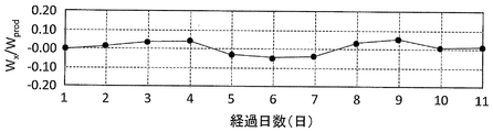
- FIG. 2 is a graph showing the fluctuation of W x / W prod with respect to the number of elapsed days.
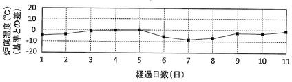
- FIG. 3 is a graph showing the fluctuation of the furnace bottom temperature with respect to the elapsed days.
- the hot metal produced in the blast furnace is mainly heated by the heat generated by the sensible heat of hot air in the lower part of the blast furnace and the combustion of carbonaceous materials.
- endothermic reactions such as a solution loss reaction and a reduction reaction of water contained in the air blown at the tuyere also occur in the lower part of the blast furnace.
- Heat loss due to heat removal from the lower furnace stave also occurs as heat removal from the lower furnace wall.
- T Q furnace heat index (MJ / t-pig) disclosed in Patent Document 2.
- T Q is expressed by the following equation (3).
- T Q Q 1 + Q 2- (Q 3 + Q 4 + Q 5 + Q 6 ) ...
- Q 1 represents a combustion heat of the tuyere coke (MJ / t-pig).
- Q 1 represents an amount of heat generated by combustion of the coke which is calculated from the amount of oxygen that is blown from tuyeres into the blast furnace per unit time can be calculated by dividing the hot metal amount which is produced in the unit time.
- Q 2 is a blast sensible heat is introduced into the blast furnace by the blast from the tuyere (MJ / t-pig).
- Q 2 are determined the amount of heat introduced into the blast furnace by the blowing from the blowing amount per unit time and the measured value of the air temperature per unit time, this value, dividing by hot metal amount which is produced in the unit time Can be calculated with.
- Q 3 is a solution loss reaction heat (MJ / t-pig). From the difference between the amount of carbon burned by blowing air per unit time and the amount of discharged carbon obtained from the concentration analysis values of CO gas and CO 2 gas in the upper part of the blast furnace, the amount of carbon consumed by the reaction in the furnace in that unit time is calculated. It can be calculated, and the solution loss reaction heat can be calculated from the amount of carbon consumed.
- Q 3 are the reaction heat can be calculated by dividing the hot metal amount which is produced in the unit time.
- Q 4 are a moisture degradation heat contained in the main blower (MJ / t-pig).
- Q 4 are, the decomposition heat per unit obtained from the measured value of the air humidity time can be calculated by dividing the hot metal amount which is produced in the unit time.
- Q 5 is a heat extraction amount of cooling water (MJ / t-pig).
- Q 5 calculates the heat removal amount per unit time by the cooling water from the temperature difference between the inlet side and the outlet side of the cooling water quantity of cooling water and blast furnace body, the heat extraction amount is produced in the unit time It can be calculated by dividing by the amount of hot metal.
- Q 6 is an exploded heat of the reducing material to be blown from the tuyere per unit time.
- Q 6 is the heat of decomposition can be calculated by dividing the hot metal amount which is produced in the unit time.
- the amount of heat added to the coke supplied from the blast furnace to the lower part of the blast furnace and the heat generated by the ore-based raw material may be apportioned between the hot metal and the molten slag, and the calculated amount of heat supplied to the hot metal may be used.
- the sensible heat brought out by the gas can be calculated by multiplying the temperature difference between the estimated temperature of the gas burned in front of the tuyere and the reference temperature representing the upper end of the lower part of the blast furnace by the specific heat of the gas in the blast furnace.
- the sensible heat of the raw material supplied to the lower part of the blast furnace can be calculated by multiplying the temperature difference between the estimated temperature of the lower end of the cohesive zone of 1450 to 1500 ° C. and the above reference temperature by the specific heat of the raw material. Since the values obtained by these treatments are distributed to the melt existing in the lower part of the blast furnace, the value obtained by multiplying the ratio of the specific heat of the hot metal in the total considering the mass ratio of the specific heat of the hot metal and the slag is the hot metal. It can be regarded as the amount of heat supplied.
- the reference temperature is 800 to 1200 ° C, preferably 900 to 1000 ° C.
- FIG. 1 is a graph showing the relationship between the hot metal temperature and the furnace heat index T Q in the steady state.
- the horizontal axis of FIG. 1 is the furnace heat index T Q (difference from the reference T Q ) (MJ / t-pig), and the vertical axis is the hot metal temperature (difference from the reference hot metal temperature) (° C.).
- the difference between the calculated amount of hot metal charged from the amount of raw material charged into the blast furnace per day and the actual amount of hot metal discharged from the blast furnace on that day is within 5% by mass. It is the state of blast furnace operation at that time.
- the blast furnace operation in the steady state may be referred to as the steady operation.
- the hot metal temperature in the following description is the average value of the hot metal temperature of the day, but in FIG. 1, the intermediate value of the hot metal temperature is set as the reference hot metal temperature (1500 ° C. in the example shown in FIG. It is shown by the difference of.
- W prod Q pig ⁇ W drine ⁇ ⁇ ⁇ (4)
- W prod (t-pig) is the amount of hot metal (t) produced in the blast furnace during the time t from the end of the previous tapping to the end of the current tapping, and is W.
- the drain is the amount of hot metal (t) released this time from the blast furnace.
- Q pig (MJ / t-pig) is the amount of heat possessed by the hot metal at the hot metal temperature T pig (° C.), and can be calculated by the following equation (5).
- a and b are constants determined by the component concentration of the hot metal exposed.
- W drain can be calculated by the following equation (6).
- W rain W prod + W x ... (6)
- W x is the amount of coagulated product (t-pig), which is a positive value when the coagulated product is dissolved and a negative value when the coagulated product is solidified.
- Eq. (8) is expressed by Eq. (1) below.
- Equation (1) above indicates that when the solidified layer melts and decreases, hot metal at a temperature lower than that during steady operation is produced with respect to the amount of heat supplied to the lower part of the blast furnace. ..
- this relationship is utilized, and the amount of heat supplied to the hot metal in the lower part of the blast furnace ( ⁇ ⁇ T Q ) is the amount of heat of the hot metal (a ⁇ T pig + b). If it becomes more than that, it is judged that the calorific value of the difference is used for melting the solidified layer and the solidified layer in the lower part of the blast furnace is reduced.
- the above equation (2) indicates that when the solidified layer grows, hot metal with a higher amount of heat is discharged from the amount of heat supplied to the lower part of the blast furnace as compared with the case of steady operation.
- this relationship is utilized, and the amount of heat supplied to the hot metal in the lower part of the blast furnace ( ⁇ ⁇ T Q ) is the amount of heat of the hot metal (a ⁇ T pig + b).
- ⁇ ⁇ T Q the amount of heat supplied to the hot metal in the lower part of the blast furnace
- the amount of heat supplied to the hot metal in the lower part of the blast furnace during a predetermined period ( ⁇ ⁇ T Q ) and the amount of heat of the hot metal discharged (a ⁇ T pig). + B) and are used to detect fluctuations in the solidified layer at the bottom of the blast furnace.
- the amount of heat supplied to the hot metal in the lower part of the blast furnace ( ⁇ ⁇ T Q ) and the amount of heat of the hot metal discharged (a ⁇ T pig + b) are calculated, and ( ⁇ ⁇ T Q ) and ( ⁇ ⁇ T Q) and ( When a ⁇ T pig + b) satisfies the above equation (1), it is determined that the solidified layer has decreased in the predetermined period.
- ( ⁇ ⁇ T Q ) and (a ⁇ T pig + b) satisfy the above equation (2), it is determined that the solidified layer has grown in the predetermined period.
- the predetermined period for calculating ( ⁇ ⁇ T Q ) and (a ⁇ T pig + b) is preferably a period from the end of the previous hot metal tapping to the end of the current hot metal tapping. Since the temperature and component value of the hot metal are measured each time the hot metal is ejected, T pig (° C.) can be obtained by using the value, and the constants a and b can be obtained by using the component value. Can be sought.
- the predetermined period is the period from the end of the previous hot metal tapping to the end of the current hot metal tapping, as long as it is a period in which " ⁇ ⁇ T Q " and "a ⁇ T pig + b" can be obtained. Not exclusively.
- the T pig value of each hot metal from the end of any hot metal to the end of any hot metal is weighted and averaged by the amount of hot metal at each hot metal, and the T Q value of the period is also weighted averaged.
- the values may be used to obtain each value within an arbitrary period.
- a blast furnace operation method that promotes melting of the solidification layer by increasing the target heat input amount and increasing the heat supply amount to the lower part of the blast furnace furnace is available. Will be implemented.
- the target heat input amount is reduced to reduce the amount of heat supplied to the lower part of the blast furnace, or the amount of heat extracted from the lower part of the blast furnace is increased.
- a blast furnace operating method that promotes the growth of the solidified layer is implemented.
- As a method for reducing the amount of heat supplied to the blast furnace bottom may be operated to increase the heat losses shown in the Q 5. As a result, fluctuations in the solidified layer at the bottom of the blast furnace can be suppressed, and stable blast furnace operation can be realized.
- FIG. 2 is a graph showing the fluctuation of W x / W prod with respect to the number of elapsed days.
- the horizontal axis of FIG. 2 is the number of elapsed days (days), and the vertical axis is W x / W prod .
- the W x / W prod decreased on the 5th day after the lapse of days. Reduction of W x / W prod, this means that W x / W prod becomes negative, to satisfy the above expression (2). Therefore, it is possible to detect that the solidified layer in the lower part of the blast furnace has grown on the 5th day after the lapse of days.
- FIG. 3 is a graph showing fluctuations in the bottom temperature with respect to the number of days elapsed in the same blast furnace operation.
- the horizontal axis of FIG. 3 is the number of elapsed days (days), and the vertical axis is the furnace bottom temperature (° C.).
- the bottom temperature is the value of a thermometer installed in the center of the bottom plate of the blast furnace bottom.
- the furnace bottom temperature decreased on the 6th day after the lapse of days. It is probable that this decrease in the bottom temperature is due to the growth of the solidified layer on the bottom, which reduces the amount of heat transferred from the inside of the furnace to the bottom. That is, it can be seen that the detection of the fluctuation of the solidified layer due to the furnace bottom temperature is slower than the detection using the amount of heat supplied to the lower part of the blast furnace and the hot metal temperature at which the hot metal is exposed. From this result, it was confirmed that the increase / decrease of the solidified layer in the lower part of the blast furnace can be detected at an early stage by implementing the method for detecting the fluctuation of the solidified layer according to the present embodiment.
Landscapes
- Engineering & Computer Science (AREA)
- Chemical & Material Sciences (AREA)
- Manufacturing & Machinery (AREA)
- Materials Engineering (AREA)
- Metallurgy (AREA)
- Organic Chemistry (AREA)
- Blast Furnaces (AREA)
- Manufacture Of Iron (AREA)
Abstract
Description
[1]所定期間における高炉炉下部の溶銑に供給される熱量と、出銑される溶銑の熱量と、を用いて高炉炉下部の凝固層の変動を検知する、凝固層の変動検知方法。
[2]下記(1)式を満足する場合に前記凝固層が成長したと判断し、下記(2)式を満足する場合に前記凝固層が減少したと判断する、[1]に記載の凝固層の変動検知方法。
α×TQ>a×Tpig+b・・・(1)
α×TQ<a×Tpig+b・・・(2)
上記(1)式および(2)式において、αは、前記凝固層の増減がない定常状態における前記高炉炉下部に供給される熱が溶銑に伝熱される比率であり、TQは、高炉炉下部に供給される熱量の指標である炉熱指数(MJ/t-pig)であり、Tpigは、前記出銑される溶銑の温度(℃)であり、a、bは、前記出銑される溶銑の成分濃度によって定まる定数である。
[3]前記所定期間は、前回の溶銑出銑終了後から今回の溶銑出銑終了後までの期間である、[1]または[2]に記載の凝固層の変動検知方法。
[4][1]から[3]の何れか1つに記載の凝固層の変動検知方法を用いて高炉炉下部の凝固層の変動を検知し、前記凝固層が成長した場合には前記凝固層の融解を促進させ、前記凝固層が減少した場合には前記凝固層の成長を促進させる、高炉操業方法。
TQ=Q1+Q2-(Q3+Q4+Q5+Q6)・・・(3)
上記(4)式において、Wprod(t-pig)は、前回の出銑終了後、今回の出銑終了までの時間tの間に高炉内で製造された溶銑量(t)であり、Wdrainは、高炉から今回出銑された溶銑量(t)である。Qpig(MJ/t-pig)は、溶銑温度Tpig(℃)の溶銑が有する熱量であり、下記(5)式で算出できる。
上記(5)式において、a、bは、出銑された溶銑の成分濃度によって定まる定数である。種々の成分濃度の溶銑に対応した定数「a、b」の値は、予め把握されている。例えば、炭素濃度が4~5質量%の溶銑においてはa=0.84、b=84である。
上記(6)式において、Wxは凝固物量(t-pig)であり、凝固物が溶解した場合には正の値となり、凝固物が凝固した場合には負の値となる。(5)式および(6)式を上記(4)式に代入すると上記(4)式は、下記(7)式で表わされる。
Wx/Wprod=[α×TQ/(a×Tpig+b)]-1=1-1=0・・・(10)
Claims (4)
- 所定期間における高炉炉下部の溶銑に供給される熱量と、出銑される溶銑の熱量と、を用いて高炉炉下部の凝固層の変動を検知する、凝固層の変動検知方法。
- 下記(1)式を満足する場合に前記凝固層が成長したと判断し、下記(2)式を満足する場合に前記凝固層が減少したと判断する、請求項1に記載の凝固層の変動検知方法。
α×TQ>a×Tpig+b・・・(1)
α×TQ<a×Tpig+b・・・(2)
上記(1)式および(2)式において、αは、前記凝固層の増減がない定常状態における前記高炉炉下部に供給される熱が溶銑に伝熱される比率であり、
TQは、高炉炉下部に供給される熱量の指標である炉熱指数(MJ/t-pig)であり、
Tpigは、前記出銑される溶銑の温度(℃)であり、
a、bは、前記出銑される溶銑の成分濃度によって定まる定数である。 - 前記所定期間は、前回の溶銑出銑終了後から今回の溶銑出銑終了後までの期間である、請求項1または請求項2に記載の凝固層の変動検知方法。
- 請求項1から請求項3の何れか一項に記載の凝固層の変動検知方法を用いて高炉炉下部の凝固層の変動を検知し、
前記凝固層が成長した場合には前記凝固層の融解を促進させ、前記凝固層が減少した場合には前記凝固層の成長を促進させる、高炉操業方法。
Priority Applications (7)
| Application Number | Priority Date | Filing Date | Title |
|---|---|---|---|
| US17/919,668 US12540363B2 (en) | 2020-04-30 | 2021-04-07 | Method for detecting fluctuation of solidified layer and method for operating blast furnace |
| EP21795469.2A EP4101936A4 (en) | 2020-04-30 | 2021-04-07 | METHOD FOR DETECTING FLUCTUATIONS IN A COAGULATION LAYER AND METHOD FOR OPERATING A BLAST FURNACE |
| JP2021532002A JP6947343B1 (ja) | 2020-04-30 | 2021-04-07 | 凝固層の変動検知方法および高炉操業方法 |
| CN202411327556.1A CN119320851A (zh) | 2020-04-30 | 2021-04-07 | 凝固层的变动检测方法及高炉操作方法 |
| CN202180030929.7A CN115485396A (zh) | 2020-04-30 | 2021-04-07 | 凝固层的变动检测方法及高炉操作方法 |
| BR112022021550-9A BR112022021550B1 (pt) | 2020-04-30 | 2021-04-07 | Método para detectar flutuação de camada solidificada e método para operar alto-forno |
| KR1020227037778A KR20220154826A (ko) | 2020-04-30 | 2021-04-07 | 응고층의 변동 검지 방법 및 고로 조업 방법 |
Applications Claiming Priority (2)
| Application Number | Priority Date | Filing Date | Title |
|---|---|---|---|
| JP2020-080085 | 2020-04-30 | ||
| JP2020080085 | 2020-04-30 |
Publications (1)
| Publication Number | Publication Date |
|---|---|
| WO2021220751A1 true WO2021220751A1 (ja) | 2021-11-04 |
Family
ID=78331527
Family Applications (1)
| Application Number | Title | Priority Date | Filing Date |
|---|---|---|---|
| PCT/JP2021/014778 Ceased WO2021220751A1 (ja) | 2020-04-30 | 2021-04-07 | 凝固層の変動検知方法および高炉操業方法 |
Country Status (2)
| Country | Link |
|---|---|
| TW (1) | TWI778576B (ja) |
| WO (1) | WO2021220751A1 (ja) |
Cited By (1)
| Publication number | Priority date | Publication date | Assignee | Title |
|---|---|---|---|---|
| WO2025150235A1 (ja) * | 2024-01-09 | 2025-07-17 | Jfeスチール株式会社 | 高炉の制御方法及び制御装置 |
Families Citing this family (1)
| Publication number | Priority date | Publication date | Assignee | Title |
|---|---|---|---|---|
| JP7786618B2 (ja) * | 2023-12-22 | 2025-12-16 | Jfeスチール株式会社 | 高炉の制御方法及び制御装置 |
Citations (6)
| Publication number | Priority date | Publication date | Assignee | Title |
|---|---|---|---|---|
| JPS5732308A (en) * | 1980-08-04 | 1982-02-22 | Kawasaki Steel Corp | Method for operating blast furnace |
| JPH02115311A (ja) | 1988-10-25 | 1990-04-27 | Kawasaki Steel Corp | 高炉の炉熱制御方法 |
| JPH07278627A (ja) * | 1994-04-13 | 1995-10-24 | Nippon Steel Corp | 高炉炉底冷却配管および高炉炉底冷却方法 |
| JPH10273708A (ja) * | 1997-03-28 | 1998-10-13 | Nippon Steel Corp | 高炉炉底状況の推定方法 |
| JP2007077440A (ja) * | 2005-09-13 | 2007-03-29 | Kobe Steel Ltd | 高炉の減尺休風操業方法 |
| JP2016006221A (ja) | 2014-05-28 | 2016-01-14 | 株式会社神戸製鋼所 | 竪型炉における溶滓量計測方法、及びその計測装置 |
Family Cites Families (1)
| Publication number | Priority date | Publication date | Assignee | Title |
|---|---|---|---|---|
| CN105005632B (zh) * | 2014-04-17 | 2017-11-28 | 宝山钢铁股份有限公司 | 多层耐火砖炉墙结构的高炉炉缸侵蚀预测方法 |
-
2021
- 2021-04-07 WO PCT/JP2021/014778 patent/WO2021220751A1/ja not_active Ceased
- 2021-04-14 TW TW110113439A patent/TWI778576B/zh active
Patent Citations (6)
| Publication number | Priority date | Publication date | Assignee | Title |
|---|---|---|---|---|
| JPS5732308A (en) * | 1980-08-04 | 1982-02-22 | Kawasaki Steel Corp | Method for operating blast furnace |
| JPH02115311A (ja) | 1988-10-25 | 1990-04-27 | Kawasaki Steel Corp | 高炉の炉熱制御方法 |
| JPH07278627A (ja) * | 1994-04-13 | 1995-10-24 | Nippon Steel Corp | 高炉炉底冷却配管および高炉炉底冷却方法 |
| JPH10273708A (ja) * | 1997-03-28 | 1998-10-13 | Nippon Steel Corp | 高炉炉底状況の推定方法 |
| JP2007077440A (ja) * | 2005-09-13 | 2007-03-29 | Kobe Steel Ltd | 高炉の減尺休風操業方法 |
| JP2016006221A (ja) | 2014-05-28 | 2016-01-14 | 株式会社神戸製鋼所 | 竪型炉における溶滓量計測方法、及びその計測装置 |
Non-Patent Citations (1)
| Title |
|---|
| YOSHIKAWA FUMIAKI: "Estimation of refractory wear and solidified layer distribution in the blast furnace hearth and its application to the operation", TETSU-TO-HAGANE, vol. 73, no. 15, 1987, pages 2068,2075 |
Cited By (2)
| Publication number | Priority date | Publication date | Assignee | Title |
|---|---|---|---|---|
| WO2025150235A1 (ja) * | 2024-01-09 | 2025-07-17 | Jfeスチール株式会社 | 高炉の制御方法及び制御装置 |
| JP7722610B1 (ja) * | 2024-01-09 | 2025-08-13 | Jfeスチール株式会社 | 高炉の制御方法及び制御装置 |
Also Published As
| Publication number | Publication date |
|---|---|
| TWI778576B (zh) | 2022-09-21 |
| TW202142700A (zh) | 2021-11-16 |
Similar Documents
| Publication | Publication Date | Title |
|---|---|---|
| CN115516113A (zh) | 高炉操作方法 | |
| WO2021220751A1 (ja) | 凝固層の変動検知方法および高炉操業方法 | |
| EP2877606B1 (en) | Starting a smelting process | |
| JP6947343B1 (ja) | 凝固層の変動検知方法および高炉操業方法 | |
| JP5411466B2 (ja) | 鉄浴式溶解炉およびそれを用いた溶鉄製造方法 | |
| JP5068116B2 (ja) | 連続溶解炉のスラグフォーミング抑制方法 | |
| JP5181877B2 (ja) | 竪型スクラップ溶解炉を用いた溶銑製造方法 | |
| RU2810028C1 (ru) | Способ обнаружения флуктуации отвердевшего слоя и способ эксплуатации доменной печи | |
| JP2001181727A (ja) | 電気炉の炉内状況監視方法 | |
| JP5079444B2 (ja) | 転炉内壁面のスラグコーティング方法 | |
| RU2810028C9 (ru) | Способ обнаружения флуктуации отвердевшего слоя и способ эксплуатации доменной печи | |
| RU2825340C1 (ru) | Способ определения количества подводимого тепла, устройство для определения количества подводимого тепла и способ работы доменной печи | |
| JP7626931B2 (ja) | 高炉の操業方法 | |
| RU2812287C1 (ru) | Способ работы доменной печи | |
| JP4992407B2 (ja) | 竪型スクラップ溶解炉を用いた溶銑製造方法 | |
| JP2025091779A (ja) | 溶鉄の吹錬方法及び溶鋼の製造方法 | |
| WO2025182165A1 (ja) | 高炉の操業方法 | |
| JP5721009B2 (ja) | 溶解炉の操業方法 | |
| JP4123034B2 (ja) | 転炉を用いた固体金属源溶解方法および溶融還元方法 | |
| JPS6137908A (ja) | 転炉操業法 | |
| JPS6239225B2 (ja) | ||
| RU2389799C1 (ru) | Способ выплавки стали | |
| Ristiana et al. | Temperature control of cupola melting | |
| JP2004225141A (ja) | 高炉操業における炉芯活性化方法 | |
| JPH08157913A (ja) | 高炉の操業法 |
Legal Events
| Date | Code | Title | Description |
|---|---|---|---|
| ENP | Entry into the national phase |
Ref document number: 2021532002 Country of ref document: JP Kind code of ref document: A |
|
| 121 | Ep: the epo has been informed by wipo that ep was designated in this application |
Ref document number: 21795469 Country of ref document: EP Kind code of ref document: A1 |
|
| WWE | Wipo information: entry into national phase |
Ref document number: 202217047085 Country of ref document: IN |
|
| ENP | Entry into the national phase |
Ref document number: 2021795469 Country of ref document: EP Effective date: 20220908 |
|
| ENP | Entry into the national phase |
Ref document number: 20227037778 Country of ref document: KR Kind code of ref document: A |
|
| REG | Reference to national code |
Ref country code: BR Ref legal event code: B01A Ref document number: 112022021550 Country of ref document: BR |
|
| NENP | Non-entry into the national phase |
Ref country code: DE |
|
| ENP | Entry into the national phase |
Ref document number: 112022021550 Country of ref document: BR Kind code of ref document: A2 Effective date: 20221024 |
|
| WWR | Wipo information: refused in national office |
Ref document number: 1020227037778 Country of ref document: KR |
|
| WWG | Wipo information: grant in national office |
Ref document number: 17919668 Country of ref document: US |
|
| WWC | Wipo information: continuation of processing after refusal or withdrawal |
Ref document number: 1020227037778 Country of ref document: KR |
|
| WWG | Wipo information: grant in national office |
Ref document number: 202217047085 Country of ref document: IN |