WO2021220960A1 - Cellule à flux redox - Google Patents
Cellule à flux redox Download PDFInfo
- Publication number
- WO2021220960A1 WO2021220960A1 PCT/JP2021/016452 JP2021016452W WO2021220960A1 WO 2021220960 A1 WO2021220960 A1 WO 2021220960A1 JP 2021016452 W JP2021016452 W JP 2021016452W WO 2021220960 A1 WO2021220960 A1 WO 2021220960A1
- Authority
- WO
- WIPO (PCT)
- Prior art keywords
- electrode
- redox flow
- battery according
- flow battery
- recess
- Prior art date
- Legal status (The legal status is an assumption and is not a legal conclusion. Google has not performed a legal analysis and makes no representation as to the accuracy of the status listed.)
- Ceased
Links
Images



Classifications
-
- H—ELECTRICITY
- H01—ELECTRIC ELEMENTS
- H01M—PROCESSES OR MEANS, e.g. BATTERIES, FOR THE DIRECT CONVERSION OF CHEMICAL ENERGY INTO ELECTRICAL ENERGY
- H01M8/00—Fuel cells; Manufacture thereof
- H01M8/18—Regenerative fuel cells, e.g. redox flow batteries or secondary fuel cells
- H01M8/184—Regeneration by electrochemical means
- H01M8/188—Regeneration by electrochemical means by recharging of redox couples containing fluids; Redox flow type batteries
-
- H—ELECTRICITY
- H01—ELECTRIC ELEMENTS
- H01M—PROCESSES OR MEANS, e.g. BATTERIES, FOR THE DIRECT CONVERSION OF CHEMICAL ENERGY INTO ELECTRICAL ENERGY
- H01M4/00—Electrodes
- H01M4/86—Inert electrodes with catalytic activity, e.g. for fuel cells
-
- H—ELECTRICITY
- H01—ELECTRIC ELEMENTS
- H01M—PROCESSES OR MEANS, e.g. BATTERIES, FOR THE DIRECT CONVERSION OF CHEMICAL ENERGY INTO ELECTRICAL ENERGY
- H01M4/00—Electrodes
- H01M4/86—Inert electrodes with catalytic activity, e.g. for fuel cells
- H01M4/96—Carbon-based electrodes
-
- H—ELECTRICITY
- H01—ELECTRIC ELEMENTS
- H01M—PROCESSES OR MEANS, e.g. BATTERIES, FOR THE DIRECT CONVERSION OF CHEMICAL ENERGY INTO ELECTRICAL ENERGY
- H01M8/00—Fuel cells; Manufacture thereof
- H01M8/02—Details
-
- H—ELECTRICITY
- H01—ELECTRIC ELEMENTS
- H01M—PROCESSES OR MEANS, e.g. BATTERIES, FOR THE DIRECT CONVERSION OF CHEMICAL ENERGY INTO ELECTRICAL ENERGY
- H01M8/00—Fuel cells; Manufacture thereof
- H01M8/02—Details
- H01M8/0202—Collectors; Separators, e.g. bipolar separators; Interconnectors
- H01M8/023—Porous and characterised by the material
-
- H—ELECTRICITY
- H01—ELECTRIC ELEMENTS
- H01M—PROCESSES OR MEANS, e.g. BATTERIES, FOR THE DIRECT CONVERSION OF CHEMICAL ENERGY INTO ELECTRICAL ENERGY
- H01M8/00—Fuel cells; Manufacture thereof
- H01M8/02—Details
- H01M8/0202—Collectors; Separators, e.g. bipolar separators; Interconnectors
- H01M8/023—Porous and characterised by the material
- H01M8/0234—Carbonaceous material
-
- H—ELECTRICITY
- H01—ELECTRIC ELEMENTS
- H01M—PROCESSES OR MEANS, e.g. BATTERIES, FOR THE DIRECT CONVERSION OF CHEMICAL ENERGY INTO ELECTRICAL ENERGY
- H01M8/00—Fuel cells; Manufacture thereof
- H01M8/02—Details
- H01M8/0202—Collectors; Separators, e.g. bipolar separators; Interconnectors
- H01M8/0247—Collectors; Separators, e.g. bipolar separators; Interconnectors characterised by the form
-
- H—ELECTRICITY
- H01—ELECTRIC ELEMENTS
- H01M—PROCESSES OR MEANS, e.g. BATTERIES, FOR THE DIRECT CONVERSION OF CHEMICAL ENERGY INTO ELECTRICAL ENERGY
- H01M8/00—Fuel cells; Manufacture thereof
- H01M8/02—Details
- H01M8/0202—Collectors; Separators, e.g. bipolar separators; Interconnectors
- H01M8/0258—Collectors; Separators, e.g. bipolar separators; Interconnectors characterised by the configuration of channels, e.g. by the flow field of the reactant or coolant
-
- H—ELECTRICITY
- H01—ELECTRIC ELEMENTS
- H01M—PROCESSES OR MEANS, e.g. BATTERIES, FOR THE DIRECT CONVERSION OF CHEMICAL ENERGY INTO ELECTRICAL ENERGY
- H01M8/00—Fuel cells; Manufacture thereof
- H01M8/18—Regenerative fuel cells, e.g. redox flow batteries or secondary fuel cells
-
- H—ELECTRICITY
- H01—ELECTRIC ELEMENTS
- H01M—PROCESSES OR MEANS, e.g. BATTERIES, FOR THE DIRECT CONVERSION OF CHEMICAL ENERGY INTO ELECTRICAL ENERGY
- H01M8/00—Fuel cells; Manufacture thereof
- H01M8/20—Indirect fuel cells, e.g. fuel cells with redox couple being irreversible
-
- Y—GENERAL TAGGING OF NEW TECHNOLOGICAL DEVELOPMENTS; GENERAL TAGGING OF CROSS-SECTIONAL TECHNOLOGIES SPANNING OVER SEVERAL SECTIONS OF THE IPC; TECHNICAL SUBJECTS COVERED BY FORMER USPC CROSS-REFERENCE ART COLLECTIONS [XRACs] AND DIGESTS
- Y02—TECHNOLOGIES OR APPLICATIONS FOR MITIGATION OR ADAPTATION AGAINST CLIMATE CHANGE
- Y02E—REDUCTION OF GREENHOUSE GAS [GHG] EMISSIONS, RELATED TO ENERGY GENERATION, TRANSMISSION OR DISTRIBUTION
- Y02E60/00—Enabling technologies; Technologies with a potential or indirect contribution to GHG emissions mitigation
- Y02E60/30—Hydrogen technology
- Y02E60/50—Fuel cells
Definitions
- the present invention relates to a redox flow battery.
- a redox flow battery that charges and discharges by utilizing the redox reaction of the active material contained in the electrolytic solution has been known.
- the redox flow battery has features such as easy increase in capacity, long life, and accurate monitoring of the state of charge of the battery. Due to these characteristics, in recent years, redox flow batteries have attracted a great deal of attention as applications for stabilizing the output of renewable energy and leveling the power load, especially when the amount of power generation fluctuates greatly.
- a redox flow battery is composed of a cell stack in which a plurality of battery cells are stacked in order to obtain a predetermined voltage.
- Such a redox flow battery is required to reduce the internal resistance of the battery cell and the pressure loss when the electrolytic solution passes through the battery cell in order to realize high efficiency of the entire system.
- Patent Document 1 describes a redox flow battery in which a bipolar plate constituting a battery cell is provided with a comb tooth flow path.
- the comb-tooth flow path is formed in a comb-teeth shape on the surface of the bipolar plate facing the electrode, and is composed of two types of flow path grooves, one on the supply side and the other on the discharge side, which are arranged so as to mesh with each other.
- the electrolytic solution flows in the electrode from the flow path groove on the supply side to the flow path groove on the adjacent discharge side, so that the thickness of the electrode is reduced to reduce the internal resistance and the inside of the electrode. It is expected that the flow resistance of the electrolytic solution will be reduced to reduce the pressure loss.
- the electrode in order to deal with the problem peculiar to the structure provided with the comb tooth flow path, the electrode has a two-layer structure, and the transmittance of the layer on the diaphragm side is higher than the transmittance of the layer on the bipolar plate side.
- the technology to increase the size is also described. As a result, the non-uniform flow of the electrolytic solution in the electrode can be reduced, the non-uniform flow of the electrolytic solution in the electrode becomes non-uniform, and the problem that the entire electrode is not effectively used for the reaction can be solved. Be expected.
- Patent Document 2 describes a structure provided with a flow path structure in which the electrolytic solution is circulated so as to flow in the electrode in the thickness direction.
- a flow path structure in which the electrolytic solution is circulated so as to flow in the electrode in the thickness direction.
- an object of the present invention is to provide a highly efficient and high output redox flow battery.
- the redox flow battery of the present invention has a cell frame having a recess, at least one sheet-like electrode housed in the recess, and a diaphragm laminated on the cell frame so as to close the recess. And a bipolar current collector that penetrates the cell frame in the recess and is electrically connected to at least one electrode, and the cell frame is a flow path that communicates with the recess and contains an active material. It has a flow path through which the fluid flows in the recess so that it flows parallel to the diaphragm, and at least one electrode is arranged in the recess at an angle intersecting the diaphragm.
- the flow of the electrolytic solution (fluid containing the active material) in the recess is crossed with respect to the sheet-shaped electrode without requiring a special and complicated flow path structure. Can be done. Therefore, even if the size of the battery cell is increased, the flow resistance of the electrolytic solution does not increase remarkably, and the pressure loss when the electrolytic solution passes through the battery cell does not increase significantly. Further, the fact that the flow path structure is not complicated leads to the fact that the flow of the electrolytic solution in the electrode is less likely to cause an uneven flow, and also leads to maximizing the charge / discharge performance.
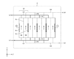
- FIG. 1A is a schematic configuration diagram of a redox flow battery according to an embodiment of the present invention.
- FIG. 1B is a schematic configuration diagram of a cell stack constituting the redox flow battery of the present embodiment.
- the redox flow battery 1 charges and discharges by utilizing the redox reaction of the positive electrode active material and the negative electrode active material in the battery cell 10, and includes a cell stack 2 having a plurality of stacked battery cells 10. ing.
- the cell stack 2 is connected to the positive electrode side tank 3 for storing the positive electrode electrolytic solution via the positive electrode side outbound pipe L1 and the positive electrode side inbound pipe L2.
- the positive electrode side outbound pipe L1 is provided with a positive electrode side pump 4 that circulates the positive electrode electrolytic solution between the positive electrode side tank 3 and the cell stack 2.
- the cell stack 2 is connected to the negative electrode side tank 5 for storing the negative electrode electrolytic solution via the negative electrode side outward path pipe L3 and the negative electrode side return path pipe L4.
- the negative electrode side outbound pipe L3 is provided with a negative electrode side pump 6 that circulates the negative electrode electrolytic solution between the negative electrode side tank 5 and the cell stack 2.
- a negative electrode side pump 6 that circulates the negative electrode electrolytic solution between the negative electrode side tank 5 and the cell stack 2.
- the electrolytic solution any fluid containing the active material, such as a slurry formed by suspending and dispersing the granular active material in the liquid phase and the liquefied active material itself, can be used. Therefore, the electrolytic solution referred to here is not limited to the solution of the active material.
- the plurality of battery cells 10 are configured by alternately stacking cell frames and diaphragms, which will be described later. The detailed configuration of the cell frame will be described later. Although four battery cells 10 are shown in FIG. 1B, the number of battery cells 10 constituting the cell stack 2 is not limited to this.
- Each battery cell 10 has a positive electrode cell 12 that houses the positive electrode 11, a negative electrode cell 14 that houses the negative electrode 13, and a diaphragm 15 that separates the positive electrode cell 12 and the negative electrode cell 14.
- the positive electrode cell 12 is connected to the positive electrode side outbound pipe L1 via the individual supply flow path P1 and the common supply flow path C1, and is connected to the positive electrode side return path pipe L2 via the individual recovery flow path P2 and the common recovery flow path C2. It is connected.
- the positive electrode electrolytic solution containing the positive electrode active material is supplied to the positive electrode cell 12 from the positive electrode side tank 3.
- the negative electrode cell 14 is connected to the negative electrode side outbound pipe L3 via the individual supply flow path P3 and the common supply flow path C3, and is connected to the negative electrode side return path pipe via the individual recovery flow path P4 and the common recovery flow path C4. It is connected to L4.
- the negative electrode electrolytic solution containing the negative electrode active material is supplied to the negative electrode cell 14 from the negative electrode side tank 5.
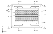
- FIG. 2 is a schematic plan view of a cell frame constituting the battery cell of the present embodiment, and shows a plane seen from the stacking direction of the cell stack.
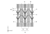
- FIG. 3 is a schematic cross-sectional view of the battery cell of the present embodiment, showing a cross section parallel to the stacking direction of the cell stack.
- the arrangement of the cell frames shown in FIGS. 2 and 3 is for convenience, and does not limit the posture when the battery cell is used. Further, the terms “upper” and “lower” in the following description are also relative and do not limit the posture when the battery cell is used.
- the cell frame 20 is formed in a rectangular plate shape, has a recess 21 on one surface (the surface on the front side of the paper surface in FIG. 2), and has a recess 22 on the other surface (the surface on the back side of the paper surface in FIG. 2). doing.
- the positive electrode 11 is housed in one recess 21, and the negative electrode 13 is housed in the other recess 22.
- the cell frame 20 and the diaphragm 15 are alternately laminated so that the diaphragm 15 closes the recesses 21 and 22, thereby forming a plurality of battery cells 10 separated by the cell frame 20.
- a positive electrode cell 12 for accommodating the positive electrode 11 is formed between one surface of the cell frame 10 and the diaphragm 15, and the negative electrode 13 is accommodated between the other surface of the cell frame 10 and the diaphragm 15.
- the negative electrode cell 14 is formed.
- the cell frame 20 is formed near four corners, and each has through holes 31 to 34 penetrating the cell frame 20 in the thickness direction Z.
- the cell frame 20 has groove-shaped slits 35 and 36 connecting the through holes 31 and 32 and the recess 21 on one surface (the surface on the front side of the paper surface in FIG. 2), and the other surface (FIG. 2).
- the surface on the back side of the paper surface of No. 2) has groove-shaped slits 37, 38 for connecting the through holes 33, 34 and the recess 22.
- the through holes 31, 32 and the slits 35, 36 communicate with the recess 21 (positive electrode cell 12) and electrolyze the positive electrode into the recess 21 when the cell frame 20 and the diaphragm 15 are alternately laminated to form the cell stack 2. It constitutes the flow paths C1, C2, P1 and P2 through which the liquid flows. Specifically, the through hole 31 and the slit 35 form a common supply flow path C1 and an individual supply flow path P1 for the positive electrode electrolyte, respectively, and the through hole 32 and the slit 36 form a common recovery for the positive electrode electrolyte, respectively.
- the flow path C2 and the individual recovery flow path P2 are configured.
- the positive electrode electrolyte is supplied from the common supply flow path C1 to the positive electrode cell 12 through the individual supply flow path P1, flows through the positive electrode cell 12 in parallel (Y direction) with the diaphragm 15, and then flows from the individual recovery flow path P2. It is recovered to the common recovery flow path C2.
- the through holes 33, 34 and the slits 37, 38 communicate with the recess 22 (negative electrode cell 14) into the recess 22 when the cell frame 20 and the diaphragm 15 are alternately laminated to form the cell stack 2. It constitutes channels C3, C4, P3, and P4 through which the negative electrode electrolyte is circulated.
- the through hole 33 and the slit 37 form a common supply flow path C3 and an individual supply flow path P3 for the negative electrode electrolyte, respectively
- the through hole 34 and the slit 38 form a common supply for the negative electrode electrolyte, respectively.
- the flow path C4 and the individual supply flow path P4 are configured.
- the negative electrode electrolytic solution is supplied from the common supply flow path C3 to the negative electrode cell 14 through the individual supply flow path P3, flows in the negative electrode cell 14 in parallel (Y direction) with the diaphragm 15, and then flows from the individual recovery flow path P4. It is recovered to the common recovery flow path C4.
- the cell frame 20 is made of an insulating material.
- a material having an appropriate rigidity, not reacting with the electrolytic solution, and having resistance to the electrolytic solution can be used.
- plastics such as vinyl chloride, polyethylene and polypropylene.
- the positive electrode electrode 11 is formed in a sheet shape and is arranged in the recess 21 so as to intersect the flow of the positive electrode electrolyte in the recess 21. Specifically, the positive electrode electrode 11 is arranged so as to be inclined in the flow direction Y with respect to a plane (ZX plane) perpendicular to the flow direction Y of the positive electrode electrolytic solution. Similarly, the negative electrode electrode 13 is also formed in a sheet shape and is arranged in the recess 22 so as to intersect the flow of the negative electrode electrolytic solution in the recess 22. Specifically, the negative electrode electrode 13 is arranged so as to be inclined in the flow direction Y with respect to a plane (ZX plane) perpendicular to the flow direction Y of the negative electrode electrolytic solution.
- the positive electrode 11 and the negative electrode 13 are arranged symmetrically with respect to both the cell frame 20 and the diaphragm 15 so as to draw a V shape in a cross section (YZ plane) perpendicular to the longitudinal direction X of the cell frame 20. There is. As a result, the positive electrode 11 and the negative electrode 13 have a periodic shape in the stacking direction Z of the cell stack 2. Further, the positive electrode electrode 11 and the negative electrode electrode 13 are supported at predetermined positions by the electrode support portion 16, which will be described in detail later.
- the material of the electrodes 11 and 13 it is preferable to use a carbon material, and for example, the electrodes 11 and 13 made of carbon paper, carbon cloth, or carbon felt can be used.
- the positive electrode 11 and the negative electrode 13 are electrically connected by a sheet-shaped bipolar current collector 40 penetrating the cell frame 20 in the recesses 21 and 22.
- the bipolar current collector 40 has a bipolar 41 and two current collectors 42 connected to both sides of the bipolar 41.
- the bipolar portion 41 is arranged in the opening 23 (see FIG. 4) formed in the recesses 21 and 22, and the gap between the bipolar portion 41 and the opening 23 is a gasket 43 (FIG. 4). See) to be liquidtightly sealed.
- the current collector 42 is a porous sheet member made of a conductive material and having a plurality of holes.
- One of the current collecting portions 42 is arranged on the upper surface of the positive electrode electrode 11 (downstream side in the flow direction Y of the positive electrode electrolytic solution) and is electrically connected to the positive electrode 11.
- the other current collecting unit 42 is arranged on the upper surface of the negative electrode electrode 13 (downstream side in the flow direction Y of the negative electrode electrolytic solution) and is electrically connected to the negative electrode 13.
- the position of the bipolar current collector 40 with respect to the electrodes 11 and 13 is not limited to this, and for example, the electrodes 11 and 13 are tilted for the purpose of improving the ease of assembly and reducing the internal resistance of the battery cell 10. It may be changed as appropriate.
- the installation position of the bipolar current collector 40 is not limited to the upper side of the electrodes 11 and 13 (downstream side in the flow direction Y of the electrolytic solution), but the lower side of the electrodes 11 and 13 (upstream in the flow direction Y of the electrolytic solution Y). It may be on the side), or it may be on both the upper and lower sides of the electrodes 11 and 13.
- the material of the bipolar current collector 40 (that is, the bipolar 41 and the current collector 42), it is preferable to use a carbon material having high conductivity and resistance to an electrolytic solution (chemical resistance, acid resistance, etc.), for example. , Plastic carbon can be used.
- at least one of the bipolar portion 41 and the current collector portion 42 may be made of a carbon-plated metal plate.
- the structure of the current collector 42 is not limited to the porous shape as long as the electrolytic solution is allowed to pass therethrough, and may be a grid shape or a mesh shape.
- the flow of the electrolytic solution in each of the cells 12 and 14 intersects with the sheet-shaped electrodes 11 and 13.
- the pressure loss when the electrolytic solution passes through the other regions (spaces) in the recesses 21 and 22 is much higher than the pressure loss when the electrolytic solution passes through the electrodes 11 and 13. small. Therefore, the electrolytic solution passes through the entire surfaces of the sheet-shaped electrodes 11 and 13 in a state where the drift is suppressed. Therefore, in the present embodiment, the drift of the electrolytic solution in the electrodes 11 and 13 can be reduced without forming a special and complicated flow path structure in the cell frame 20.
- the cell frame 20 does not have a special and complicated flow path structure, even if the size of the battery cell 10 is increased, the flow resistance of the electrolytic solution does not increase remarkably, and the electrolytic solution is used as the battery cell 10. The pressure loss when passing through is not significantly increased. As a result, the redox flow battery 1 with high efficiency and high output can be realized.
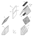
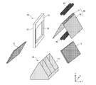
- FIG. 4 is a schematic exploded perspective view of the battery cell of the present embodiment, and partially shows a region near the recess of the cell frame.
- the cell frame 20 includes an opening 23 penetrating the cell frame 20 in the recesses 21 and 22, and the bipolar portion 41 of the bipolar current collector 40 is arranged in the opening 23.
- a gasket 43 is attached to the gap between the bipolar portion 41 and the opening 23.
- An electrode support portion 16 is arranged between the positive electrode electrode 11 and the cell frame 20 and between the negative electrode electrode 13 and the cell frame 20, respectively.
- the electrode support portion 16 has a trapezoidal outer shape in a plane (YZ plane) perpendicular to the longitudinal direction X of the cell frame 20, whereby the electrodes 11 and 13 are placed at predetermined positions (that is, in the electrolytic solution flow direction Y). It can be supported at the position where it intersects.
- each of the electrode support portions 16 has a plurality of auxiliary support plates 17 arranged along the flow direction Y of the electrolytic solution. Depending on the design, the plurality of auxiliary support plates 17 can function not only as a support mechanism for the electrodes 11 and 13, but also as a diffusion suppression mechanism for the electrolytic solution.
- the height (length in the Z direction) of the electrode support portion 16 from the bottom surface of the recesses 21 and 22 is preferably the same as the depth of the recesses 21 and 22.
- the electrode support portion 16 can also support the diaphragm 15, that is, can also function as a diaphragm support portion.
- a material having appropriate mechanical strength for supporting the electrodes 11 and 13 and resistance to an electrolytic solution can be used. Examples of such a material include plastics such as vinyl chloride, polyethylene and polypropylene.
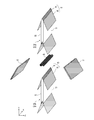
- FIG. 5 is a schematic exploded perspective view corresponding to FIG. 4, showing a modified example of the bipolar current collector of the present embodiment.
- FIG. 6 is a schematic exploded perspective view corresponding to FIG. 4, showing a modified example of the electrode support portion of the present embodiment.
- FIG. 7 is a schematic exploded perspective view corresponding to FIG. 4, showing a modified example of the cell frame of the present embodiment.
- the electrodes and the electrode support portions are not shown for the sake of simplicity.
- the modified example shown in FIG. 5 is different from the configuration shown in FIG. 4 in that the bipolar portion 41 is formed in a plate shape. Along with this, the opening 23 of the cell frame 20 is formed to have a size larger than the opening shown in FIG. 4, and the current collecting portion 42 is connected to each plate surface of the bipolar portion 41.
- the modified example shown in FIG. 6 is different from the configuration shown in FIG. 4 in that one electrode support portion 16 is provided for the two electrodes 11 and 13. That is, in this modification, the electrode support portion 16 has a configuration in which the two electrode support portions shown in FIG. 4 are integrated. Along with this, the opening 23 of the cell frame 20 is formed in a size capable of accommodating the electrode support portion 16 in addition to the bipolar portion 41. In this modification, if, for example, a conductive material containing carbon is used as the material of the electrode support portion 16, the electrode support portion 16 can be made to function as a bipolar portion.
- the configuration of the cell frame 20 for fixing the bipolar current collector 40 is different from the configuration shown in FIG. Specifically, the cell frame 20 has a frame body (not shown) having an opening, and a partition plate 24 which is attached to the opening to form recesses 21 and 22.
- the partition plate 24 is divided into a plurality of regions 24a and 24b along the flow direction Y of the electrolytic solution, and the upper end portions of the respective regions 24a and 24b are formed in a ridge shape and the lower end portion is formed in a groove shape.
- the two bipolar current collectors 40 can be sandwiched and fixed between the two adjacent regions 24a and 24b of the partition plate 24.
- the bipolar current collector 40 is fixed at a predetermined position with respect to the cell frame 20 (that is, a position intersecting the flow direction Y of the electrolytic solution), the electrodes 11 and 13 are adjacent to the two current collectors. It can be sandwiched and fixed to the portion 42 and supported at a predetermined position. That is, the current collector 42 can function as the electrode support, and the electrode support 16 described above can be omitted.
- one of the two bipolar current collectors 40 between the two regions 24a and 24b is a porous, lattice-shaped, or mesh-shaped member made of a non-conductive material such as plastic. May be replaced with.
- a diaphragm supporting portion for supporting the diaphragm 15 may be separately provided in the recesses 21 and 22.
- the two positive electrode 11s are arranged in the recess 21, and the two negative electrodes 13 are arranged in the recess 22, but the electrodes 11 in each recess 21 and 22
- the number of 13 is not limited to this, and may be one or three or more. Further, even when the number of electrodes 11 and 13 in the recesses 21 and 22 is three or more, the same as in the present embodiment from the viewpoint of reducing the internal resistance of the battery cell 10 and the pressure loss of the electrolytic solution. , They are preferably arranged at intervals from each other in the flow direction Y of the electrolytic solution. As a result, even when the number of electrodes 11 and 13 in the recesses 21 and 22 is increased to increase the output of the redox flow battery 1, the decrease in charge / discharge efficiency can be minimized.
- the postures (angles) of the electrodes 11 and 13 in the recesses 21 and 22 specifically flow with respect to the plane (ZX plane) perpendicular to the flow direction Y of the electrolytic solution as long as they intersect the diaphragm 15.
- the specific inclination angle is not limited to a specific angle.
- the angle may be different between the positive electrode 11 and the negative electrode 13 connected to the common bipolar current collector 40, and may be different between the electrodes 11 and 13 of the same type in the different battery cells 10. However, if the distance between the positive electrode 11 and the negative electrode 13 sandwiching the diaphragm 15 is increased, the internal resistance of the battery cell 10 will increase.
- the positive electrode 11 and the negative electrode 13 are arranged symmetrically with respect to the diaphragm 15.
- Examples of such a suitable arrangement include those shown in FIG. 3 and those shown in FIG. 8 in addition to those shown in FIG. 3 described above.
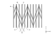
- 8A and 8B are schematic cross-sectional views showing other suitable arrangement examples of electrodes in the cell stack of this embodiment.
- the current collector 42 may be arranged on any one of the two surfaces of the electrodes 11 and 13, or as shown by the broken line in FIG. 8, each electrode 11 , 13 may be arranged on either of the two surfaces.
- the plurality of positive electrodes 11 in the recess 21 are not electrically connected to each other, and the plurality of negative electrodes 13 in the recess 22 are not electrically connected to each other.
- the non-uniformity of the internal potential is remarkable in each of the cells 12 and 14, and a decrease in charge / discharge efficiency may become a problem.
- the plurality of positive electrodes 11 may be electrically connected to each other, and the plurality of negative electrodes 13 may also be electrically connected to each other. .. Therefore, a conductive member that electrically connects two adjacent bipolar portions 41 may be installed inside the cell frame 20. Alternatively, by using the plate-shaped bipolar portion 41 as shown in FIG. 5, even if the bipolar portion 41 common to the plurality of positive electrode electrodes 11 and common to the plurality of negative electrode electrodes 13 is provided. good.
- each of the slits 35 to 38 may be branched into a plurality of slits and connected to the recesses 21 and 22 at different positions in the longitudinal direction X of the cell frame 20.
- the electrolytic solution can be dispersed and supplied in the longitudinal direction X of the cell frame 20, and the above-mentioned effect of suppressing the drift can be enhanced.
- the plurality of battery cells 10 are connected to each other so that each electrolytic solution flows in parallel through the plurality of battery cells 10, but the connection mode of the plurality of electric cells 10 is limited to this. is not it.
- the plurality of battery cells 10 may be connected to each other so that each electrolytic solution flows through the plurality of battery cells 10 in series, that is, a series flow path may be formed.
- the plurality of battery cells 10 have a hierarchical flow path configuration in which a parallel flow path and a series flow path are combined, specifically, a flow path structure in which a plurality of series flow paths are connected in parallel. You may. That is, the cell stack 2 may be divided into a plurality of cell groups, a plurality of battery cells 10 constituting each cell group may form a series flow path, and each cell group may form a parallel flow path.
- the positive electrode side tank 3 is divided into two tanks, a tank connected to the pipe L1 and a tank connected to the pipe L2, and these two tanks.
- two types of positive electrode electrolytes having different ratios of the active material concentration in the reduced state and the active material concentration in the oxidized state may be separately stored. That is, the positive electrode electrolyte may be stored in separate tanks before and after the redox reaction during the charge / discharge operation.
- the negative electrode side tank 5 is divided into two tanks, a tank connected to the pipe L3 and a tank connected to the pipe L4, and the ratio of the active material concentration in the reduced state to the active material concentration in the oxidized state in these two tanks.
- Two types of negative electrode electrolytes having different values may be stored separately. That is, the negative electrode electrolyte may be stored in separate tanks before and after the redox reaction during the charge / discharge operation.
- Redox flow battery 10 Battery cell 11 Positive electrode 12 Positive cell 13 Negative electrode 14 Negative cell 15 Diaphragm 16 Electrode support 17 Auxiliary support plate 20 Cell frame 21 and 22 Recesses 23 Openings 24 Partition plates 31 to 34 Through holes 35 to 38 Slit 40 Bipolar current collector 41 Bipolar collector 42 Current collector 43 Gasket
Landscapes
- Chemical & Material Sciences (AREA)
- Chemical Kinetics & Catalysis (AREA)
- Electrochemistry (AREA)
- General Chemical & Material Sciences (AREA)
- Life Sciences & Earth Sciences (AREA)
- Engineering & Computer Science (AREA)
- Manufacturing & Machinery (AREA)
- Sustainable Development (AREA)
- Sustainable Energy (AREA)
- Fuel Cell (AREA)
Abstract
Priority Applications (3)
| Application Number | Priority Date | Filing Date | Title |
|---|---|---|---|
| JP2022518019A JPWO2021220960A1 (fr) | 2020-04-28 | 2021-04-23 | |
| CN202180030337.5A CN115485893A (zh) | 2020-04-28 | 2021-04-23 | 氧化还原液流电池 |
| US17/921,895 US20230197996A1 (en) | 2020-04-28 | 2021-04-23 | Redox flow battery |
Applications Claiming Priority (2)
| Application Number | Priority Date | Filing Date | Title |
|---|---|---|---|
| JP2020079485 | 2020-04-28 | ||
| JP2020-079485 | 2020-04-28 |
Publications (1)
| Publication Number | Publication Date |
|---|---|
| WO2021220960A1 true WO2021220960A1 (fr) | 2021-11-04 |
Family
ID=78373570
Family Applications (1)
| Application Number | Title | Priority Date | Filing Date |
|---|---|---|---|
| PCT/JP2021/016452 Ceased WO2021220960A1 (fr) | 2020-04-28 | 2021-04-23 | Cellule à flux redox |
Country Status (4)
| Country | Link |
|---|---|
| US (1) | US20230197996A1 (fr) |
| JP (1) | JPWO2021220960A1 (fr) |
| CN (1) | CN115485893A (fr) |
| WO (1) | WO2021220960A1 (fr) |
Cited By (1)
| Publication number | Priority date | Publication date | Assignee | Title |
|---|---|---|---|---|
| WO2023026745A1 (fr) * | 2021-08-26 | 2023-03-02 | 東洋エンジニアリング株式会社 | Batterie à flux rédox |
Citations (3)
| Publication number | Priority date | Publication date | Assignee | Title |
|---|---|---|---|---|
| JP2012146469A (ja) * | 2011-01-11 | 2012-08-02 | Sumitomo Electric Ind Ltd | レドックスフロー電池、レドックスフロー電池セル、及びレドックスフロー電池用セルスタック |
| US9184454B1 (en) * | 2012-12-21 | 2015-11-10 | Vizn Energy Systems, Incorporated | Mixing arrangement for a flow cell of an energy storage system |
| WO2018105155A1 (fr) * | 2016-12-07 | 2018-06-14 | 住友電気工業株式会社 | Plaque bipolaire, empilement de cellules et batterie à flux rédox |
Family Cites Families (9)
| Publication number | Priority date | Publication date | Assignee | Title |
|---|---|---|---|---|
| JP4784485B2 (ja) * | 2006-11-02 | 2011-10-05 | トヨタ自動車株式会社 | リチウム二次電池 |
| CN201838659U (zh) * | 2010-10-28 | 2011-05-18 | 比亚迪股份有限公司 | 一种全钒氧化还原液流电池的复合电极 |
| US9614244B2 (en) * | 2012-09-05 | 2017-04-04 | Ess Tech, Inc. | Redox and plating electrode systems for an all-iron hybrid flow battery |
| CN103413954B (zh) * | 2013-08-26 | 2016-03-02 | 中国东方电气集团有限公司 | 膜电极组件、液流电池和电极的制备方法 |
| US20160036060A1 (en) * | 2014-07-30 | 2016-02-04 | Concurrent Technologies Corporation | Composite electrode for flow battery |
| KR101580405B1 (ko) * | 2014-08-14 | 2015-12-28 | 일도에프엔씨(주) | 레독스 플로우 배터리용 플로우프레임 일체형 분리판 바이폴라 플레이트 |
| AU2016391240B2 (en) * | 2016-02-03 | 2021-10-21 | Sumitomo Electric Industries, Ltd. | Redox flow battery |
| JP7001094B2 (ja) * | 2017-06-21 | 2022-01-19 | 住友電気工業株式会社 | レドックスフロー電池 |
| KR102429170B1 (ko) * | 2017-09-04 | 2022-08-03 | 현대자동차주식회사 | 리튬 공기 배터리 장치 |
-
2021
- 2021-04-23 CN CN202180030337.5A patent/CN115485893A/zh active Pending
- 2021-04-23 WO PCT/JP2021/016452 patent/WO2021220960A1/fr not_active Ceased
- 2021-04-23 US US17/921,895 patent/US20230197996A1/en active Pending
- 2021-04-23 JP JP2022518019A patent/JPWO2021220960A1/ja active Pending
Patent Citations (3)
| Publication number | Priority date | Publication date | Assignee | Title |
|---|---|---|---|---|
| JP2012146469A (ja) * | 2011-01-11 | 2012-08-02 | Sumitomo Electric Ind Ltd | レドックスフロー電池、レドックスフロー電池セル、及びレドックスフロー電池用セルスタック |
| US9184454B1 (en) * | 2012-12-21 | 2015-11-10 | Vizn Energy Systems, Incorporated | Mixing arrangement for a flow cell of an energy storage system |
| WO2018105155A1 (fr) * | 2016-12-07 | 2018-06-14 | 住友電気工業株式会社 | Plaque bipolaire, empilement de cellules et batterie à flux rédox |
Cited By (1)
| Publication number | Priority date | Publication date | Assignee | Title |
|---|---|---|---|---|
| WO2023026745A1 (fr) * | 2021-08-26 | 2023-03-02 | 東洋エンジニアリング株式会社 | Batterie à flux rédox |
Also Published As
| Publication number | Publication date |
|---|---|
| CN115485893A (zh) | 2022-12-16 |
| US20230197996A1 (en) | 2023-06-22 |
| JPWO2021220960A1 (fr) | 2021-11-04 |
Similar Documents
| Publication | Publication Date | Title |
|---|---|---|
| EP0800709B1 (fr) | Agencements de cellules electrolytiques et de piles a combustible | |
| EP1821357B1 (fr) | Cellule unitaire pour une pile à combustible à électrolyte polymère solide | |
| US10230123B2 (en) | Battery cell and redox flow battery | |
| CN103250290B (zh) | 燃料电池和燃料电池组 | |
| WO2016072191A1 (fr) | Élément de batterie et batterie à circulation rédox | |
| WO2020129022A2 (fr) | Batterie à flux redox comprenant un empilement de cadres d'écoulement et cadre à flux redox associé | |
| US20220238904A1 (en) | Redox flow battery | |
| WO2021220960A1 (fr) | Cellule à flux redox | |
| JP2005228645A (ja) | レドックスフロー電池セル、電池および電極の保持構造 | |
| JP2017134919A (ja) | セルフレームおよびフロー電池 | |
| WO2023026745A1 (fr) | Batterie à flux rédox | |
| JP7435479B2 (ja) | 電池セル、セルスタック、及びレドックスフロー電池 | |
| JP2005347107A (ja) | レドックスフロー電池セルおよびレドックスフロー電池 | |
| JP2018188710A (ja) | 水電解装置 | |
| WO2020158623A1 (fr) | Cellule de batterie, empilement de cellules et batterie à flux redox | |
| JPWO2020158625A1 (ja) | 電池セル、セルスタック、及びレドックスフロー電池 | |
| JP7803796B2 (ja) | レドックスフロー電池 | |
| WO2024017014A1 (fr) | Ensemble électrode à membrane non uniforme pour pile à combustible, et pile à combustible | |
| KR20240132263A (ko) | 용접된 4층 모듈들의 스택을 갖는 전해조 | |
| US20190157699A1 (en) | Cell frame and redox flow battery | |
| JP2025065057A (ja) | 電池 | |
| CN117476992A (zh) | 一种小流阻的轻量化液流电池 | |
| JP2020129502A (ja) | 電池セル、セルスタック、及びレドックスフロー電池 |
Legal Events
| Date | Code | Title | Description |
|---|---|---|---|
| 121 | Ep: the epo has been informed by wipo that ep was designated in this application |
Ref document number: 21797160 Country of ref document: EP Kind code of ref document: A1 |
|
| ENP | Entry into the national phase |
Ref document number: 2022518019 Country of ref document: JP Kind code of ref document: A |
|
| NENP | Non-entry into the national phase |
Ref country code: DE |
|
| 122 | Ep: pct application non-entry in european phase |
Ref document number: 21797160 Country of ref document: EP Kind code of ref document: A1 |
|
| WWE | Wipo information: entry into national phase |
Ref document number: 522441071 Country of ref document: SA |
|
| WWR | Wipo information: refused in national office |
Ref document number: 522441071 Country of ref document: SA |