WO2021221016A1 - Pcf装置、af装置、nef装置、及びこれらの方法 - Google Patents
Pcf装置、af装置、nef装置、及びこれらの方法 Download PDFInfo
- Publication number
- WO2021221016A1 WO2021221016A1 PCT/JP2021/016655 JP2021016655W WO2021221016A1 WO 2021221016 A1 WO2021221016 A1 WO 2021221016A1 JP 2021016655 W JP2021016655 W JP 2021016655W WO 2021221016 A1 WO2021221016 A1 WO 2021221016A1
- Authority
- WO
- WIPO (PCT)
- Prior art keywords
- information
- identifier
- cell
- information includes
- request
- Prior art date
- Legal status (The legal status is an assumption and is not a legal conclusion. Google has not performed a legal analysis and makes no representation as to the accuracy of the status listed.)
- Ceased
Links
Images


Classifications
-
- H—ELECTRICITY
- H04—ELECTRIC COMMUNICATION TECHNIQUE
- H04L—TRANSMISSION OF DIGITAL INFORMATION, e.g. TELEGRAPHIC COMMUNICATION
- H04L12/00—Data switching networks
- H04L12/02—Details
- H04L12/14—Charging, metering or billing arrangements specially adapted for data communications, e.g. authentication, authorisation and accounting [AAA] framework
- H04L12/1403—Architecture for metering, charging or billing
- H04L12/1407—Policy-and-charging control [PCC] architecture
-
- H—ELECTRICITY
- H04—ELECTRIC COMMUNICATION TECHNIQUE
- H04W—WIRELESS COMMUNICATION NETWORKS
- H04W36/00—Hand-off or reselection arrangements
- H04W36/12—Reselecting a serving backbone network switching or routing node
- H04W36/125—Reselecting a serving backbone network switching or routing node involving different types of service backbones
-
- H—ELECTRICITY
- H04—ELECTRIC COMMUNICATION TECHNIQUE
- H04W—WIRELESS COMMUNICATION NETWORKS
- H04W24/00—Supervisory, monitoring or testing arrangements
- H04W24/02—Arrangements for optimising operational condition
-
- H—ELECTRICITY
- H04—ELECTRIC COMMUNICATION TECHNIQUE
- H04W—WIRELESS COMMUNICATION NETWORKS
- H04W36/00—Hand-off or reselection arrangements
- H04W36/0005—Control or signalling for completing the hand-off
- H04W36/0011—Control or signalling for completing the hand-off for data sessions of end-to-end connection
-
- H—ELECTRICITY
- H04—ELECTRIC COMMUNICATION TECHNIQUE
- H04W—WIRELESS COMMUNICATION NETWORKS
- H04W36/00—Hand-off or reselection arrangements
- H04W36/34—Reselection control
- H04W36/38—Reselection control by fixed network equipment
-
- H—ELECTRICITY
- H04—ELECTRIC COMMUNICATION TECHNIQUE
- H04W—WIRELESS COMMUNICATION NETWORKS
- H04W48/00—Access restriction; Network selection; Access point selection
- H04W48/08—Access restriction or access information delivery, e.g. discovery data delivery
- H04W48/12—Access restriction or access information delivery, e.g. discovery data delivery using downlink control channel
-
- H—ELECTRICITY
- H04—ELECTRIC COMMUNICATION TECHNIQUE
- H04W—WIRELESS COMMUNICATION NETWORKS
- H04W76/00—Connection management
- H04W76/10—Connection setup
- H04W76/11—Allocation or use of connection identifiers
-
- H—ELECTRICITY
- H04—ELECTRIC COMMUNICATION TECHNIQUE
- H04W—WIRELESS COMMUNICATION NETWORKS
- H04W76/00—Connection management
- H04W76/10—Connection setup
- H04W76/15—Setup of multiple wireless link connections
Definitions
- the present disclosure relates to a wireless communication network, and particularly to control of a user plane route (path).
- Patent Document 1 discloses that a mobile terminal is handed over from a macro cell to the small cell in order to enable the mobile terminal to use a special service provided only in a specific small cell.
- the mobile terminal resides in a macro cell provided by a radio base station (hereinafter referred to as a macro cell base station), and a service establishment request requesting the establishment of a specific service is made to the macro cell base station.
- a radio base station hereinafter referred to as a macro cell base station
- MME Mobility Management Entity
- the core network node requests the macrocell base station to establish the requested specific service in response to the reception of the service establishment request from the mobile terminal.
- SGSN Serving GPRS Support Node
- MME Mobility Management Entity
- the macro cell base station manages a table showing which type of specific service is provided in each of a plurality of small cells.
- the macrocell base station selects a small cell associated with the requested specific service based on the table, and determines whether or not the mobile terminal can be handed over to the selected small cell. The determination is made based on, for example, whether or not a radio wave having a predetermined intensity or higher reaches the macrocell base station from the mobile terminal.
- the macrocell base station sends a response indicating the failure of service establishment to the core network node, and the mobile station is handed over to the selected small cell.
- the radio base station that provides the small cell (hereinafter referred to as a small cell base station) notifies the core network node of the completion of the handover.
- the core network node requests the small cell base station to establish a specific service.
- the above-mentioned table is managed by a core network node (e.g., SGSN or MME) instead of a macrocell base station.
- the core network node refers to the table associated with the macrocell base station in response to the reception of the service establishment request from the mobile terminal via the macrocell base station, and associates it with the requested specific service.
- the selected small cell is selected, and it is determined whether or not the mobile terminal can be handed over to the selected small cell. The determination is made based on, for example, whether or not a radio wave having a predetermined intensity or higher reaches the macrocell base station from the mobile terminal.
- the core network node requests the macro cell base station to perform the handover.
- the macrocell base station handovers the mobile station from the macrocell to the small cell in response to the handover execution request from the core network node.
- the small cell base station notifies the core network node of the completion of the handover.
- the core network node requests the small cell base station to establish a specific service.
- Non-Patent Document 1 for example, Section 5.6.7
- Non-Patent Document 2 for example, Section 4.3.6
- SMF Session Management Function
- PDU Protocol Data Unit
- Send to 5GC AF requests affect User Plane Function (UPF) selection by the SMF, directing user traffic to local access to the Data Network (DN) identified by the DN Access Identifier (DNAI). Allows you to route.
- UPF selection by SMF involves inserting a UL Classifier (ULCL) UPF or Branching Point (BP) UPF into the User Plane (UP) path of a PDU session.
- ULCL User Plane Function
- BP Branching Point
- the 5G system supports millimeter-wave frequency bands (bands) from 4.25 GHz to 52.6 GHz in addition to the 6 GHz or less (sub-6 GHz) frequency bands (bands) used in Long Term Evolution (LTE). do.
- the sub-6 GHz frequency band (bands) is called Frequency Range 1 (FR1)
- the millimeter wave frequency band (bands) is called Frequency Range 2 (FR2).
- FR2 band 5G Next Radio (NR) devices can exchange data over a wider carrier bandwidth and achieve very low scheduling latency.
- FR2 cells will be local cells (local cells or small cells) arranged in FR1 cells (cells).
- a wireless terminal When a wireless terminal (hereinafter referred to as User Equipment (UE)) desires a specific service, the inventor or the like may use a specific cell (for example, a specific frequency band (eg, FR2)) suitable for the specific service.
- a specific cell for example, a specific frequency band (eg, FR2)
- FR2 a specific frequency band
- the application server (or the control server associated with it) requests the wireless communication network (eg, 5G system) to provide the UE with an UP route that includes the wireless connection of a specific cell (eg, FR2 cell). If possible, this may contribute to improving the user experience.
- the wireless communication network eg, 5G system
- a specific cell eg, FR2 cell
- Patent Document 1 does not disclose, for example, that the application function (AF) requires the core network to hand over the UE to a specific cell (e.g., FR2 cell).
- AF application function
- AF influence on traffic routing described in Non-Patent Documents 1 and 2 enables AF to request the core network to change the UP route.
- Non-Patent Documents 1 and 2 do not disclose the procedure by which AF requires the core network to provide an UP route including a radio connection of a specific cell (e.g., FR2 cell).
- One of the objectives to be achieved by the embodiments disclosed herein is to provide the wireless communication network with an UP route containing a wireless connection of a specific cell based on a request from an application function (AF).
- AF application function
- the Application Function (AF) device includes at least one memory and at least one processor coupled to the at least one memory.
- the at least one processor is configured to send a first message to the core network.
- the first message states that the user plane route is set up or modified so that the user data for the User Equipment (UE) is transferred via the user plane route including the wireless connection of a specific cell. Request from the core network.
- UE User Equipment
- the core network device includes at least one memory and at least one processor coupled to the at least one memory.
- the at least one processor is configured to receive a second message based on a request from the Application Function (AF) from another core network node.
- the at least one processor further responds to the second message so that user data for User Equipment (UE) is transferred over a user plane path that includes a radio connection for a particular cell. It is configured to require the radio access network (RAN) to set up or modify the user plane route.
- RAN radio access network
- the method performed by the Application Function (AF) device comprises sending a first message to the core network.
- the first message states that the user plane route is set up or modified so that the user data for the User Equipment (UE) is transferred via the user plane route including the wireless connection of a specific cell. Request from the core network.
- UE User Equipment
- the method performed by the core network device comprises the following steps: (A) Receiving a second message based on the request from the Application Function (AF) from another core network node, and (b) Responding to the second message for the User Equipment (UE). Requesting a radio access network (RAN) to set up or modify the user plane route so that user data is transferred over the user plane route that includes the radio connection of a particular cell.
- A Receiving a second message based on the request from the Application Function (AF) from another core network node, and (b) Responding to the second message for the User Equipment (UE).
- UE User Equipment
- RAN radio access network
- the program includes an instruction group (software code) for causing the computer to perform the method according to the third or fourth aspect described above when read by the computer.
- a device, method which contributes to enabling a wireless communication network to provide a UE with an UP route containing a wireless connection of a particular cell based on a request from an application function (AF). And programs can be provided.
- AF application function
- the plurality of embodiments described below can be implemented independently or in combination as appropriate. These plurality of embodiments have novel features that differ from each other. Therefore, these plurality of embodiments contribute to solving different purposes or problems, and contribute to different effects.
- the plurality of embodiments shown below will be described mainly for the 5th generation mobile communication system (5G system (5GS)). However, these embodiments may be applied to other wireless communication systems (e.g., LTE systems).
- 5G system 5th generation mobile communication system
- LTE systems Long Term Evolution
- FIG. 1 shows a configuration example of a wireless communication network (ie, 5GS) according to some embodiments including the present embodiment.
- Each of the elements shown in FIG. 1 is a network function and provides an interface defined by the 3rd Generation Partnership Project (3GPP).
- 3GPP 3rd Generation Partnership Project
- Each element (network function) shown in FIG. 1 is, for example, as a network element on dedicated hardware, as a running software instance on dedicated hardware, or on an application platform. It can be implemented as an instantiated virtualization function.
- the wireless communication network shown in FIG. 1 may be provided by a Mobile Network Operator (MNO) or a Non-Public Network (NPN) provided by a non-MNO.
- MNO Mobile Network Operator
- NPN Non-Public Network
- the wireless communication network shown in FIG. 1 may be an independent network represented by Stand-alone Non-Public Network (SNPN) or linked with an MNO network represented by Public network integrated NPN. It may be an NPN.
- the radio communication network includes a radio access network (RadioAccessNetwork (RAN) 10, 5G core network (5GC) 30, and application function (AF) 41.
- RAN 10 includes RAN nodes 1 and 2.
- 5GC30 includes Access and Mobility Management Function (AMF) 31, Session Management Function (SMF) 32, User Plane Function (UPF) 33, Policy Control Function (PCF) 34, and Network Exposure Function (NEF) 35.
- AMF Access and Mobility Management Function
- SMF Session Management Function
- UPF User Plane Function
- PCF Policy Control Function
- NEF Network Exposure Function
- Each of RAN nodes 1 and 2 may be gNB or ng-eNB.
- RAN nodes 1 and 2 may be Central Units (e.g., gNB-CU) in the cloud RAN (C-RAN) deployment.
- the RAN node 1 terminates the control plane (CP) interface (i.e., N2 interface) with the 5GC30 and interworkes with the AMF31 in the 5GS30 on the CP interface.
- the RAN node 2 may also terminate the CP interface (i.e., N2 interface) with the 5GC30 and interwork with the AMF31 on the CP interface.
- RAN node 2 does not have to have a CP interface with any AMF. For example, if the RAN node 2 is responsible for only the secondary node (SN) of the dual connectivity (DC) in a non-standalone arrangement, the RAN node 2 does not have a CP interface with the 5GC30. good.
- RAN node 1 provides one or more cells including cell 11, and RAN node 2 provides one or more cells including cell 12.
- the cell 11 may operate in a frequency band different from that of the cell 12.
- cell 11 may operate in any sub-6 GHz frequency band within FR1 and cell 12 may operate in any millimeter wave frequency band within FR2.
- the cell 12 in the high frequency band may be a local cell (small cell) arranged in the cell 11 in the low frequency band.
- the cell 11 may completely cover the cell 12 or may partially overlap the cell 12.
- AMF31 is one of the network functions in the 5GC control plane.
- the AMF31 provides the termination of the RANCP interface (i.e., N2 interface).
- AMF31 terminates one (single) signaling connection (ie, N1 Non-Access Stratum (NAS) signaling connection) with UE3, registration management (registration management), connection management (connection management), and mobility management (mobility). management) is provided.
- AMF31 provides NF services (services) to NF consumers (e.g. other AMF, SMF32, and Authentication Server Function (AUSF)) on a service-based interface (i.e., Namf interface).
- NF services provided by other NFs (e.g., Unified Data Management (UDM), Network Slice Selection Function (NSSF), and PCF34).
- UDM Unified Data Management
- NSSF Network Slice Selection Function
- PCF34 PCF34
- the SMF32 is one of the network functions in the 5GC control plane.
- the SMF 32 manages the PDU session.
- the SMF 32 sends and receives SM signaling messages (NAS-SM messages) to and from the Non-Access Stratum (NAS) Session Management (SM) layer of the UE 3 via the communication service provided by the AMF 31.
- the SMF 32 provides NF services (services) to NF consumers (e.g., AMF31, other SMFs) on a service-based interface (i.e., Nsmf interface).
- the NF service provided by SMF32 includes a PDU session management service (Nsmf_PDUSession).
- the NF service allows the NF consumer (e.g., AMF31) to handle PDU sessions.
- the SMF 32 may be an Intermediate SMF (I-SMF).
- the I-SMF is inserted between the AMF 31 and the original SMF as needed when the UPF 33 belongs to a different SMF service area and
- UPF33 is one of the network functions in the 5GC user plane.
- the UPF33 processes and forwards user data.
- the functionality of the UPF33 is controlled by the SMF32.
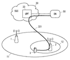
- the UPF33 interconnects with the data network (DN) 50 and acts as an anchor point towards the DN50 for one or more PDU sessions in UE3.
- the UPF 33 may include a plurality of UPFs interconnected via an N9 interface. More specifically, the UP route for a UE3 PDU session can include one or more PDU Session Anchor (PSA) UPFs and one or more Intermediate UPFs (I-UPFs). Can include one or more Uplink Classifier (ULCL) UPFs (or Branching Point (BP) UPFs).
- PSA PDU Session Anchor
- I-UPFs Intermediate UPFs
- ULCL Uplink Classifier
- BP Branching Point
- PCF34 provides various policy controls including policy control for session management related functions and policy control for access and mobility related functions. For example, PCF34 interacts with AF41 directly (via the N5 interface) or via NEF35 and interacts with SMF32 (via the N7 interface) for session management-related policy control. ..
- NEF35 has a role similar to Service Capability Exposure Function (SCEF) of Evolved Packet System (EPS). Specifically, the NEF35 supports the exposure of services and capabilities from the 5G system to applications and network functions inside and outside the operator network.
- SCEF Service Capability Exposure Function
- EPS Evolved Packet System
- the wireless terminal (i.e., UE) 3 uses the 5G connection (connectivity) service to communicate with the data network (DN) 50. More specifically, UE3 is connected to RAN10 and communicates with DN50 at the application layer via UPF33 in 5GC30.
- the term "application layer” as used herein means all protocol layers above the PDU session (PDU session layer) between UE3 and DN50 provided by 5GS. For example, if the PDUs are IP packets, the application layer is a transport layer protocol between IP and the application protocol, in addition to application protocols such as Hypertext Transfer Protocol (HTTP) and File Transfer Protocol (FTP). Includes (eg, User Datagram Protocol (UDP) and Transmission Control Protocol (TCP)).
- HTTP Hypertext Transfer Protocol
- FTP File Transfer Protocol
- Includes eg, User Datagram Protocol (UDP) and Transmission Control Protocol (TCP)).
- AF41 interacts with PCF34 to require 5GC30 to control the policy regarding the UE3 PDU session.
- AF41 interacts with PCF34 either directly or via NEF35.
- AF41 is a running application (running) on the processor of UE3 via DN50 (eg, the internet, or other IP network) and a PDU session between DN50 and UE3. Can communicate with UE applications).
- DN50 eg, the internet, or other IP network
- AF41 may include one or more computers.
- AF41 cooperates with one or more servers (eg, content distribution server, online game server) that communicate with UE3 at the application layer, and one or more of these servers, and 5GC30 (eg, PCF34).
- the AF41 may include a controller that interacts with (ie AF in the 3GPP definition). Further, the AF41 may include a plurality of distributed servers. For example, AF41 may include one or more edge computing servers located near RAN10 in addition to the central server. The edge computing server and the local UPF that provides steering of user plane traffic for local access to the edge computing server may be colllocated with any RAN node or with RAN10. It may be juxtaposed at the network aggregation site with CN30.
- the configuration example in FIG. 1 shows only typical NFs for convenience of explanation.
- the wireless communication network according to this embodiment may include other NFs not shown in FIG.
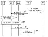
- FIG. 2 shows an example of signaling according to this embodiment.
- 5GC30 and RAN10 take an UP route in which user data belonging to the PDU session of UE3 includes a radio connection (eg, Data Radio bearer (DRB)) of a specific cell.
- DRB Data Radio bearer
- User data belonging to a UE3 PDU session may be one or more quality of service (QoS) flows.
- QoS quality of service
- the UP route is the N3 tunnel between UPF33 (specifically PSA UPF) and RAN10 (specifically RAN node 1 or 2) in 5GC30, and RAN10 (specifically RAN node 1 or 2). Includes wireless connection (DRB) to and from UE3.
- the UP route may further include one or more N9 tunnels between the UPFs.
- the N3 tunnel and the N9 tunnel may be a General Packet Radio Service (GPRS) Tunneling Protocol for User Plane (GTP-U) tunnel.
- GPRS General Packet Radio Service
- the procedure shown in FIG. 2 is started (or triggered) by AF41 when UE3 is in cell 11 (e.g., FR1 macrocell) provided by RAN node 1.
- AF41 requests 5GC30 to direct traffic belonging to the UE3 PDU session (ie, 1 or higher QoS flow) to the UP route through cell 12 (eg, FR2 local cell) provided by RAN node 2. .. Therefore, here, the particular cell is the cell 12 provided by the RAN node 2.
- AF41 sends an AF request to 5GC30.
- the AF41 sends an AF request to the PCF34 directly or via the NEF35.
- the AF request requires the 5GC30 to set up or modify the UP route so that user data belonging to the PDU session for UE3 is transferred via the UP route including the radio connection in cell 12.
- the AF request modifies the established PDU session so that user data belonging to the established PDU session for UE3 is forwarded over the UP path including the wireless connection in cell 12. Require 5GC30 to do.
- the AF request may cause the 5GC30 to control RAN10 to add cell 12 as a secondary cell (DC) secondary cell for UE3. good.
- AF41 may request 5GC30 to add cell 12 as an SCG cell of DC for UE3 via the AF request.
- Dual connectivity refers to the Master Cell Group (MCG) provided by the Master Node (MN) (eg, RAN node 1) and the Secondary Cell Group (SCG) provided by the Secondary Node (SN) (eg, RAN node 2). Allows UE to use at the same time.
- MCG is a group of serving cells associated with (or provided with) a RAN node (eg, RAN node 1) that acts as a DC MN, SpCell (ie, Primary Cell (PCell)) and, if necessary. Includes (optionally) one or more secondary cells (Secondary Cells (SCells)), while the SCG is associated (or provided) with a RAN node (eg, RAN node 2) that acts as the SN of the DC.
- MCG Master Cell Group
- SCG Secondary Cell Group
- SN Secondary Node
- SCG primary cells are primary SCG cells. (PSCell)) or primary / secondary cell (Primary Secondary Cell (PSCell)).
- PSCell is a Special Cell (SpCell) of SCG.
- the AF request may cause the 5GC30 to control the RAN10 to hand over the UE3 to the cell 12.
- the AF 41 may request the 5GC30 to hand over the UE 3 to the cell 12 via the AF request.
- the AF 41 may include a cell identifier (e.g., Physical Cell ID (PCI)) that uniquely identifies the cell 12 in the AF request.
- AF41 may include a list of cell identifiers in the AF request.
- 5GC30 e.g., SMF32
- RAN10 e.g., RAN node 1
- 5GC30 e.g., SMF32
- RAN10 e.g., RAN node 1
- 5GC30 e.g., SMF32
- RAN10 e.g., RAN node 1
- the AF41 may include a list of frequency band identifiers (e.g., NR Absolute Radio Frequency Channel Numbers (NR-ARFCNs)) of one or more frequency bands in the AF request.
- frequency band identifiers e.g., NR Absolute Radio Frequency Channel Numbers (NR-ARFCNs)
- 5GC30 e.g, SMF32 or AMF31
- RAN10 e.g, RAN node 1
- RFSP index Frequency Selection Priority
- the RFSP index is used by the RAN 10 to derive UE-specific cell reselection priorities, for example, to control camping in idle mode.
- the RFSP index is used by RAN10 to determine to redirect a UE in connected mode (active mode) to a different frequency layer or a different RAT.
- RAN10 may select one or more specific cells (including cell 12) operating in any frequency band selected based on the RFSP index instructed by AF41.
- the AF41 may include the Additional Radio Resource Management (RRM) Policy Index (ARPI) in the AF request.
- RRM Radio Resource Management
- ARPI is used by RAN10 to prioritize the allocation of RAN resources to UEs.
- the AF request in step 201 may include other information elements. More specifically, the AF request may include a UE3 identifier.
- the UE3 identifier may be a Generic Public Subscription Identifier (GPSI) such as Mobile Subscriber Integrated Services Digital Network Number (MSISDN) or external identifier.
- GPSI Generic Public Subscription Identifier
- MSISDN Mobile Subscriber Integrated Services Digital Network Number
- the AF request may include a PDU session identifier (e.g., PDU Session ID).
- the AF request may include information (e.g., 5-tuple) for identifying one or more QoS flows contained in the PDU session.
- the AF request may include a combination of Data Network Name (DNN) and Single Network Slice Selection Assistance Information (S-NSSAI).
- DNN Data Network Name
- S-NSSAI Single Network Slice Selection Assistance Information
- DNN is an identifier indicating a DN, and indicates a DN (e.g., DN50) to which UE3 traffic should be routed.
- S-NSSAI is a network slice identifier.
- the AF request may include a list of one or more DN Access Identifiers (DNAIs).
- DNAI (s) represents the access location to the DN.
- One or both of 5GC30 eg, PCF34, SMF32, AMF31
- RAN10 eg, RAN node 1
- PCI PCI
- NR-ARFCN NR-ARFCN
- RFSP index RFPI set in the AF request for each UE, PDU. It may be managed for each session, for each S-NSSAI, for each QoS Flow Identifier (QFI), for each DN, or for each DNN (for each APN).
- QFI QoS Flow Identifier
- the AMF31 may have a specific PDU session specified by AF41, a specific S-NSSAI, a specific QFI, a specific DN, or a specific.
- the RFSP index and ARPI specified by AF41 may be used only when dealing with the DNN (specific APN) of.
- RAN10 may have a particular PDU session specified by AF41, a particular S-NSSAI, a particular QFI, a particular DN.
- the RFSP index (and ARPI) specified by AF41 may be used only when dealing with a specific DNN (specific APN).
- AF41 receives a report from UE3 via communication at the application layer, and based on that report, whether a particular cell (eg, cell 12) is available to UE3. You may judge.
- the report from UE3 may include one or any combination of the current location of UE3, a list of cells measured or detected by UE3, and the radio quality measurement results for each of one or more cells. ..
- the radio quality may be, for example, Reference Signal Received Power (RSRP) or Reference Signal Received Quality (RSRQ).
- RSRP Reference Signal Received Power
- RSRQ Reference Signal Received Quality
- the AF 41 may transmit the AF request in step 201. Such an operation can prevent an AF request with a low probability of success from being sent to the 5GC30.
- the 5GC30 sends the N2 request to the RAN node 1 in the RAN 10. More specifically, the PCF34 receives the AF request directly or via the NEF35, makes policy decisions based on the AF request, and sends updated or new Session Management (SM) policy information to the SMF32. Judge that it is necessary.
- the updated or new SM policy information may include PCI (s), NR-ARFCN (s), RFSP index, or ARPI sent from AF41.
- the PCF34 then provides the updated or new SM policy information to the SMF32.
- the PCF34 may issue an Npcf_SMPolicyControl_UpdateNotify request with the updated or new SM policy information.
- the SMF32 receives the SM policy information updated or generated based on the AF request from the PCF34.
- the SMF 32 may interact with the UPF 33 to alter the UP path of one or more QoS flows belonging to the established PDU session of UE3. For example, SMF32 requests UPF33 to set up a new N3 tunnel to determine the use of split PDU sessions and route existing or additional QoS flows to RAN node 2, and new packet detection and forwarding rules. May be provided to UPF33. Further or instead, the SMF 32 may decide to insert a UL CL UPF and an additional PSA UPF into the UP path of the established PDU session of UE3. In this case, the SMF 32 may provide the UPF 33 with N9 tunnel settings for inserting UL CL UPFs and additional PSA UPFs, as well as packet detection and forwarding rules.
- 5GC30 sends an N2 request to RAN node 1.
- the N2 request may be a PDU SESSION RESOURCE MODIFY REQUEST message.
- the N2 request includes any or any combination of the cell identifier, frequency band identifier, RFSP index, and ARPI of cell 12.
- the N2 request sets up or modifies the user plane route so that the user data belonging to the PDU session for UE3 is transferred via the UP route including the radio connection in cell 12.
- the N2 request may request RAN node 1 to add cell 12 as a DC SCG cell for UE3.
- SMF32 implements Namf_Communication_N1N2MessageTransfer (invoke) and sends N2SM information and N1SM container to AMF31.
- the N1 SM container contains a PDU Session Modification Command message sent to UE3.
- N2SM information is information necessary for routing the QoS flow to be added or updated (eg PDU Session ID, QoS Flow Identifier (s) (QFI (s)), and QoS Profile (s), CN Tunnel. Info) is included.
- CNTunnelInfo indicates the N3 (GTP-U) tunnel endpoint of UPF33.
- the N2SM information may further include PCI (s), NR-ARFCN (s), RFSPindex, or ARPI sent from AF41.
- the SMF 32 may receive a list of PCIs or a list of NR-ARFCNs. In this case, the SMF 32 may select one PCI or NR-ARFCN from the list and include the selected one in the N2SM information.
- N2SM information may explicitly indicate that dual connectivity or handover is required.
- the SMF 32 may include in Namf_Communication_N1N2MessageTransfer a cause indicating that dual connectivity or handover is required.
- the RAN node 1 receives the N2 request from the AMF31 and decides to add the cell 12 as a DC SCG cell for the UE3 or to hand over the UE3 to the cell 12.
- the RAN node 1 may cause UE3, which is RadioResourceControl (RRC) _CONNETED, to perform inter-frequency measurement.
- the RAN node 1 may create an inter-frequency measurement setting to allow the UE 3 to measure the frequency band in which the cell 12 is operating. More specifically, the RAN node 1 measures the frequency band (eg, FR2 band) in which the cell 12 operates in consideration of the radio capability of UE3 (the number of Radio Frequency (RF) chains of eg, UE3).
- RF Radio Frequency
- the RAN node 1 may send an RRC message containing the created inter-frequency measurement settings to the UE 3.
- the RRC message may be an RRC Reconfiguration message. If the RAN node 1 has already received the measurement result by UE3, the measurement in step 203 may be skipped.
- the RAN node 1 performs a secondary node (SN) addition procedure in order to add the cell 12 as a secondary cell (SCG cell). More specifically, the RAN node 1 sends an SN Addition Request message to the RAN node 2. The RAN node 2 sends an SNAdditionRequestAcknowledge message to the RAN node 1. The SN Addition Request Acknowledge message includes an SN RRC message. Then, the RAN node 1 transmits a MasterNode (MN) RRC Reconfiguration message to the UE3. The MN RRC Reconfiguration message includes the SN RRC message received from the RAN node 2 and includes the N1 SM container (PDU Session Modification Command) received from the AMF 31.
- MN MasterNode
- RAN node 1 updates the UP route with 5GC (UPF33) via the PDU session path update procedure.
- the RAN node 1 sends an N2 response to the AMF31.
- the N2 response may be a PDU SESSION RESOURCE MODIFY RESPONSE message.
- the N2 response includes N2SM information.
- the N2SM information includes ANTunnelInfo indicating the N3 (GTP-U) tunnel endpoint of the RAN node 2 which is the SN of the DC.
- step 206 the AMF 31 forwards the N2SM information received from the RAN node 1 to the SMF32, and the SMF32 updates the UPF33 based on the N2SM information.
- the UE 3 can perform DC using the cell 11 as the Master Cell Group (MCG) cell and the cell 12 as the SCG cell.
- MCG Master Cell Group
- RAN node 1 may initiate a handover procedure to move UE3 to cell 12. More specifically, the RAN node 1 sends a Handover Request message to the RAN node 2. The RAN node 2 sends a Handover Request Acknowledge message to the RAN node 1. The Handover Request Acknowledge message includes a transparent container (i.e., Handover Command message) sent to UE3. RAN node 1 forwards the Handover Command message to UE3.
- a transparent container i.e., Handover Command message
- the RAN node 2 (or RAN node 1) with respect to the radio bearer in cell 12 is referred to as 5GC (User Plane Function (UPF)) via the PDU session path update procedure. Update the UP route of.
- the UE 3 can communicate with the DN 50 via the UP path including the wireless connection of the cell 12.
- 5GC User Plane Function
- FIG. 3A shows the UP route before the UP route is changed with dual connectivity or handover.
- the UP route 301 shown in FIG. 3A is used for the transfer of all QoS flows belonging to the PDU session between DN50 and UE3.
- UP path 301 includes the radio connection (DRB) in cell 11 as well as the N3 tunnel between RAN node 1 and UPF33.
- DRB radio connection
- FIG. 3B shows the UP route after the start of dual connectivity using cell 11 as an MCG cell and cell 12 as an SCG cell.
- the UP route 311 shown in FIG. 3B is the same as the UP route 301 in FIG. 3A and is used for the transfer of one or more QoS flows configured before DC.
- UP path 312 is used for one or more newly added QoS flows belonging to the PDU session between DN50 and UE3.
- the UP path 312 includes the radio connection (DRB) of the SCG cell 12 as well as the N3 tunnel between the RAN node 2 and the UPF 33.
- DRB radio connection
- FIG. 3C also shows the UP route after the dual connectivity is started, but in FIG. 3C, the local UPF33B is inserted.
- the local UPF33B operates as a UL CL and an additional PSA. This allows the local UPF33B to forward the newly added one or more QoS flow uplink traffic to the DN50B for local access via the UP route 322. Further, the local UPF33B can forward the uplink traffic of one or more QoS flows configured before the DC to the DN50A via the UP route 321 and the central UPF33A. DN50A and DN50B are the same DN.
- the PDU session is split at the local UPF33B. The local UPF33B forwards the downlink traffic of one or more QoS flows configured before the DC to RAN node 1 (MN) and RANs the downlink traffic of one or more newly added QoS flows. Forward to node 2 (SN).
- MN RAN node 1
- SN node 2
- FIG. 3D shows the UP route after UE3 is handed over from cell 11 to cell 12.
- the UP route 331 shown in FIG. 3D is used for one or more QoS flows configured before DC, and is also used for one or more newly added QoS flows.
- NS The UP path 331 includes the radio connection (DRB) in cell 12 as well as the N3 tunnel between the RAN node 2 and the UPF 33.
- DRB radio connection
- FIG. 3E also shows the UP route after the handover is completed, but in FIG. 3E, the local UPF33B is inserted.
- the local UPF33B of FIG. 3E operates as a UL CL and an additional PSA. This allows the local UPF33B to forward the newly added one or more QoS flow uplink traffic to the DN50B for local access via the UP route 342. Further, the local UPF33B can forward the uplink traffic of one or more QoS flows configured before the DC to the DN50A via the UP route 341 and the central UPF33A. DN50A and DN50B are the same DN.
- the local UPF33B merges the downlink traffic of all QoS flows in the UE3 PDU session onto the N3 tunnel (common to UP routes 341 and 342) between the local UPF33B and the RAN node 2.
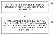
- FIG. 4 shows an example of the operation of AF41.
- AF41 receives a report from UE3 via communication at the application layer and determines whether a particular cell (eg, cell 12) is available to UE3 based on the report. ..
- the report from UE3 may show the position information (e.g., Global Positioning System (GPS) position information) of UE3 acquired by UE3.
- the report from UE3 may include a list of cells measured or detected by UE3. The list may indicate the cell identifier for each detected cell, or may indicate the frequency band in which each cell operates.
- the report from UE3 may include measurement results of radio quality (e.g., RSRP or RSRQ) of one or more cells.
- radio quality e.g., RSRP or RSRQ
- the report from UE3 may include a cell identifier representing the serving cell to which UE3 is currently connected (communication). Further or instead, the report from UE3 may indicate the radio capability of the UE. The radio capability of the UE can be used to know the NR frequency band that the UE supports and can be used to know if the UE supports DC or not.
- AF41 sets up or modifies the UP route so that user data belonging to the PDU session for UE3 is transferred over the UP route that includes the wireless connection of a particular cell. Is requested from 5GC30.
- the signaling described in this embodiment provides UE3 with an UP route including a radio connection of a specific cell (eg, FR2 cell, cell 12) based on a request from AF41. Allows wireless communication networks (5GC30 and RAN10) to do so.
- a specific cell eg, FR2 cell, cell 12
- ⁇ Second embodiment> The configuration example of the wireless communication network according to the present embodiment is the same as the example described with reference to FIG.
- the present embodiment provides specific examples of operations of UE3, AF41, and 5GC30.
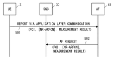
- FIG. 5 shows an example of signaling according to this embodiment.
- AF41 receives a report from UE3 via communication at the application layer.
- the report includes identifiers (e.g., PCIs) of one or more cells detected by UE3.
- the report further includes the radio quality measurements of these cells (e.g., RSRP or RSRQ).
- the report may include frequency band identifiers (e.g., NR-ARFCNs) of one or more cells detected by UE3. If AF41 has previously specified a frequency band to be measured by UE3, the report may not include the frequency band identifier of the detected cell.
- AF41 transfers user data belonging to the established PDU session for UE3 via the UP route including the radio connection of a specific cell (eg, cell 12) based on the report from UE3.
- a specific cell eg, cell 12
- the AF request transmitted by AF41 in step 502 includes a list of one or more specific cells (a list of cell identifiers (e.g., PCIs)), and further includes the measurement results of these specific cells.
- the AF request may include a list of frequency band identifiers (e.g., NR-ARFCNs) for one or more specific cells.
- the AF request may include an RFSP index (and ARPI).
- the AF request may include other information elements necessary for requesting the 5GC30 to change the QoS flow of UE3. More specifically, the AF request may include a UE3 identifier (e.g., GPSI) and QoS flow information (e.g., 5-tuple).
- the AF request may include a list of DNN and S-NSSAI, or one or more DNA Is.
- the SMF32 or the RAN node 1 can consider the measurement result of a specific cell received from the AF41 when changing the UP route based on the AF request. For example, the SMF 32 or the RAN node 1 may determine whether or not to perform dual connectivity or handover for changing the UP route based on the received measurement result. For example, SMF32 or RAN node 1 may select one specific cell preferred for UE3 from the list of specific cells based on the received measurement result.
- ⁇ Third embodiment> The configuration example of the wireless communication network according to the present embodiment is the same as the example described with reference to FIG.
- the present embodiment provides specific examples of operations of UE3, AF41, and 5GC30.
- FIG. 6 shows an example of signaling according to this embodiment.
- the AF41 receives a report from UE3 via communication at the application layer.
- the report includes identifiers (e.g., PCIs) of one or more cells detected by UE3.
- the report further includes information indicating the current location of UE3.
- the information may be GPS position information or a cell identifier representing the serving cell to which the UE3 is currently connected (communication in progress).
- the report may include frequency band identifiers (e.g., NR-ARFCNs) of one or more cells detected by UE3. If AF41 has previously specified a frequency band to be measured by UE3, the report may not include the frequency band identifier of the detected cell.
- AF41 transfers user data belonging to the established PDU session for UE3 via the UP route including the radio connection of a specific cell (eg, cell 12) based on the report from UE3.
- a specific cell eg, cell 12
- the AF request transmitted by AF41 in step 602 includes a list of one or more specific cells (a list of cell identifiers (e.g., PCIs)) and further includes information indicating the current position of UE3.
- the AF request may include a list of frequency band identifiers (e.g., NR-ARFCNs) for one or more specific cells.
- the AF request may include an RFSP index (and ARPI).
- the AF request may include other information elements necessary for requesting the 5GC30 to change the QoS flow of UE3. More specifically, the AF request may include a UE3 identifier (e.g., GPSI) and QoS flow information (e.g., 5-tuple).
- the AF request may include a list of DNN and S-NSSAI, or one or more DNA Is.
- the SMF32 or the RAN node 1 can consider the current position of the UE3 when changing the UP route based on the AF request. For example, the SMF32 or the RAN node 1 may determine whether to perform dual connectivity or handover to change the UP route based on the current position of the UE3. For example, SMF32 or RAN node 1 may select one particular cell preferred for UE3 from the list of particular cells based on the current position of UE3.
- the configuration example of the wireless communication network according to the present embodiment is the same as the example described with reference to FIG.
- the present embodiment provides specific examples of operations of UE3, RAN10, 5GC30, and AF41.
- FIG. 7 shows an example of signaling for initiating dual connectivity based on a request from AF41.
- AF41 communicates with application 700 (UE application) running one or more running on UE3.
- application 700 UE application
- AF41 may communicate with UE application 700 via an application layer above the PDU session between DN50 and UE3.
- the AF41 may receive a request for a specific service (e.g., large-capacity content distribution, online game) from the UE application 700.
- the AF41 may from the UE application 700 a list of one or more specific cells, a list of frequency bands in which these specific cells are operating, the results of these specific cell measurements by UE3, or the current position of UE3, or Any combination of these may be received.
- a specific service e.g., large-capacity content distribution, online game
- AF41 sends an AF request to PCF34 via NEF35.
- AF41 may invoke Nnef_SMPolicyControl_Update to send an AF request to NEF35.
- NEF35 may perform Npcf_SMPolicyControl_Update to forward the AF request to PCF34.
- AF41 may perform step 702B. That is. AF41 may send the AF request directly to PCF34. In step 702B, AF41 may perform Npcf_SMPolicyControl_Update to send an AF request to PCF34.
- step 704 the PCF 34 generates updated or new SM policy information based on the AF request and provides it to the SMF 32.
- PCF34 may execute Npcf_SMPolicyControl_UpdateNotify request to send updated or new SM policy information to SMF32.
- the SMF32 generates N2SM information and N1SM container based on the updated or new SM policy information.
- the N1 SM container includes a PDU Session Modification Command sent to UE3.
- N2SM information is information necessary for routing the QoS flow to be added or updated (eg PDU Session ID, QoS Flow Identifier (s) (QFI (s)), and QoS Profile (s), CN Tunnel. Info) is included.
- the SMF 32 may interact with the UPF 33 to alter the UP path of one or more QoS flows belonging to the established PDU session of UE3.
- the SMF 32 sends the N2 SM information and the N1 SM container to the AMF 31 in order to forward them to the RAN 10.
- SMF32 may carry out Namf_Communication_N1N2MessageTransfer.
- the AMF 31 In step 706, the AMF 31 generates an N2 request including the N2 SM information received from the SMF 32 and the N1 SM container, and sends this to the RAN 10 (i.e., RAN node 1).
- the N2 request may be a PDU SESSION RESOURCE MODIFY REQUEST message.
- the messages in steps 702A (or 702B), 703, 704, 705, and 706 may indicate any or any combination of PCI, NR-ARFCN list, RFSP index, and ARPI. These are associated with the UE application 700. This makes it possible to supply the RAN-related information included in the AF request from the AF 41 to the RAN 10.
- Steps 707 and 708 are the same as steps 203 and 204 in FIG.
- RAN node 1 receives an N2 request from AMF31 and decides to add cell 12 as a DC SCG cell for UE3.
- the RAN node 1 may cause UE3, which is RadioResourceControl (RRC) _CONNETED, to perform inter-frequency measurement. If the RAN node 1 has already received the measurement result by UE3, the measurement in step 707 may be skipped.
- the RAN node 1 communicates with the RAN node 2 and performs a Secondary Node (SN) addition procedure in order to add the cell 12 as a secondary cell (SCG cell).
- SN Secondary Node
- the RAN node 1 transmits an MN RRC Reconfiguration message to the UE 3.
- the MN RRC Reconfiguration message includes the SN RRC message received from the RAN node 2 and includes the N1 SM container (PDU Session Modification Command) received from the AMF 31.
- RAN node 1 sends an N2 response to AMF31.
- the N2 response may be a PDU SESSION RESOURCE MODIFY RESPONSE message.
- the N2 response includes N2SM information.
- the N2SM information includes ANTunnelInfo indicating the N3 (GTP-U) tunnel endpoint of the RAN node 2 which is the SN of the DC.
- step 711 the AMF 31 forwards the N2SM information received from the RAN node 1 to the SMF32, and the SMF32 updates the UPF33 based on the N2SM information.
- AMF31 may execute Nsmf_PDUSession_UpdateSMContextRequest.
- UE3 transmits an MN RRC Reconfiguration Complete message to RAN node 1.
- the MN RRC Reconfiguration Complete message includes an SN RRC response message for the SN, and further includes a NAS message.
- the RAN node 1 (MN) notifies the RAN node 2 (SN) of the successful completion of the UE3 reconfiguration procedure via the SN Reconfiguration Complete message including the SN RRC response message.
- the RAN node 1 forwards the NAS message received from UE3 to AMF31.
- the NAS message includes a PDU Session ID and an N1 SM container (PDU Session Modification Command Ack).
- the N2 message in step 713 may be an UPLINK NAS TRANSPORT message.
- step 714 the AMF 31 forwards the N1 SM container (PDU Session Modification Command Ack) to the SMF 32.
- AMF31 may implement Nsmf_PDUSession_UpdateSMContext.
- Steps 712 to 714 may be performed before steps 710 and 711.
- step 715 the SMF 32 sends a response to the request for updated or new SM policy information in step 704 to the PCF 34.
- SMF32 may execute Npcf_SMPolicyControl_UpdateNotify response.
- the configuration example of the wireless communication network according to the present embodiment is the same as the example described with reference to FIG.
- the present embodiment provides specific examples of operations of UE3, RAN10, 5GC30, and AF41.
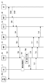
- FIG. 8 shows an example of signaling for performing a handover based on a request from AF41.
- Steps 801 to 808 are the same as those of 701 to 708 in FIG. However, in step 808, the RAN node 1 receives the N2 request from the AMF 31 and decides to hand over the UE 3 from the cell 11 to the cell 12. Then, the RAN node 1 communicates with the RAN node 2 and performs a handover preparation procedure.
- step 809 the source RAN node 1 forwards the Handover Command message received from the target RAN node 2 to the UE 3.
- RAN node 1 or RAN node 2 sends an N2 response to AMF31.
- the N2 response may be a PDU SESSION RESOURCE MODIFY RESPONSE message.
- the N2 response includes N2SM information.
- the N2SM information includes ANTunnelInfo indicating the N3 (GTP-U) tunnel endpoint of the RAN node 2 that provides the target cell 12.
- step 811 the AMF 31 forwards the N2SM information received from the RAN node 1 to the SMF32, and the SMF32 updates the UPF33 based on the N2SM information.
- UE3 accesses RAN node 2 via the target cell 12 and transmits a NAS message.
- the NAS message includes a PDU Session ID and an N1 SM container (PDU Session Modification Command Ack).
- the RAN node 2 forwards the NAS message received from the UE 3 to the AMF 31.
- the NAS message includes a PDU Session ID and an N1 SM container (PDU Session Modification Command Ack).
- the N2 message in step 713 may be an UPLINK NAS TRANSPORT message.
- step 814 the AMF 31 forwards the N1 SM container (PDU Session Modification Command Ack) to the SMF 32.
- AMF31 may implement Nsmf_PDUSession_UpdateSMContext.
- Steps 812 to 814 may be performed before steps 810 and 711.
- step 815 the SMF 32 sends a response to the request for the updated or new SM policy information in step 804 to the PCF 34.
- SMF32 may execute Npcf_SMPolicyControl_UpdateNotify response.
- FIG. 9 is a block diagram showing a configuration example of the RAN node 1 according to the above embodiment.
- the RAN node 2 may have a configuration similar to that shown in FIG.
- RAN node 1 includes a Radio Frequency (RF) transceiver 901, a network interface 903, a processor 904, and a memory 905.
- RF transceiver 901 performs analog RF signal processing to communicate with UEs.
- the RF transceiver 901 may include a plurality of transceivers.
- the RF transceiver 901 is coupled with the antenna array 902 and the processor 904.
- the RF transceiver 901 receives the modulation symbol data from the processor 904, generates a transmit RF signal, and supplies the transmit RF signal to the antenna array 902. Further, the RF transceiver 901 generates a baseband reception signal based on the reception RF signal received by the antenna array 902, and supplies the baseband reception signal to the processor 904.
- the RF transceiver 901 may include an analog beamformer circuit for beamforming.
- the analog beamformer circuit includes, for example, a plurality of phase shifters and a plurality of power amplifiers.
- the network interface 903 is used to communicate with network nodes (e.g., other RAN nodes, AMF31, and UPF33).
- the network interface 903 may include, for example, a network interface card (NIC) compliant with the IEEE 802.3 series.
- NIC network interface card
- Processor 904 performs digital baseband signal processing (data plane processing) and control plane processing for wireless communication.
- Processor 904 may include a plurality of processors.
- the processor 904 includes a modem processor (eg, Digital Signal Processor (DSP)) that performs digital baseband signal processing and a protocol stack processor (eg, Central Processing Unit (CPU) or Micro Processing Unit (eg, Central Processing Unit (CPU)) that performs control plane processing. MPU)) may be included.
- DSP Digital Signal Processor
- MPU Central Processing Unit
- digital baseband signal processing by the processor 904 is performed by the ServiceDataAdaptationProtocol (SDAP) layer, PacketDataConvergenceProtocol (PDCP) layer, RadioLinkControl (RLC) layer, MediumAccessControl (MAC) layer, and Physical (PHY). ) Layer signal processing may be included. Further, the control plane processing by the processor 904 may include processing of Non-Access Stratum (NAS) messages, RRC messages, MAC CEs, and DCIs.
- SDAP ServiceDataAdaptationProtocol
- PDCP PacketDataConvergenceProtocol
- RLC RadioLinkControl
- MAC MediumAccessControl
- PHY Physical
- Processor 904 may include a digital beamformer module for beamforming.
- the digital beamformer module may include a MultipleInputMultipleOutput (MIMO) encoder and precoder.
- MIMO MultipleInputMultipleOutput
- the memory 905 is composed of a combination of a volatile memory and a non-volatile memory.
- the volatile memory is, for example, Static Random Access Memory (SRAM) or Dynamic RAM (DRAM) or a combination thereof.
- the non-volatile memory is a mask ReadOnlyMemory (MROM), Electrically ErasableProgrammableROM (EEPROM), flash memory, or hard disk drive, or any combination thereof.
- Memory 905 may include storage located away from processor 904. In this case, processor 904 may access memory 905 via network interface 903 or an I / O interface (not shown).
- the memory 905 may store one or more software modules (computer programs) 906 including instruction groups and data for performing processing by the RAN node 1 described in the plurality of embodiments described above.
- the processor 904 may be configured to read the software module 906 from the memory 905 and execute it to perform the processing of the RAN node 1 described in the embodiments described above.
- the RAN node 1 When the RAN node 1 is the Central Unit (e.g., gNB-CU) in the C-RAN arrangement, the RAN node 1 does not have to include the RF transceiver 901 (and the antenna array 902).
- the Central Unit e.g., gNB-CU
- the RAN node 1 does not have to include the RF transceiver 901 (and the antenna array 902).
- FIG. 10 is a block diagram showing a configuration example of UE3.
- Radio Frequency (RF) transceiver 1001 performs analog RF signal processing to communicate with NG-RAN nodes.
- the RF transceiver 1001 may include a plurality of transceivers.
- the analog RF signal processing performed by the RF transceiver 1001 includes frequency up-conversion, frequency down-conversion, and amplification.
- the RF transceiver 1001 is coupled with the antenna array 1002 and the baseband processor 1003.
- the RF transceiver 1001 receives modulation symbol data (or OFDM symbol data) from the baseband processor 1003, generates a transmit RF signal, and supplies the transmit RF signal to the antenna array 1002.
- the RF transceiver 1001 generates a baseband reception signal based on the reception RF signal received by the antenna array 1002, and supplies the baseband reception signal to the baseband processor 1003.
- the RF transceiver 1001 may include an analog beamformer circuit for beamforming.
- the analog beamformer circuit includes, for example, a plurality of phase shifters and a plurality of power amplifiers.
- Baseband processor 1003 performs digital baseband signal processing (data plane processing) and control plane processing for wireless communication.
- Digital baseband signal processing includes (a) data compression / restoration, (b) data segmentation / concatenation, (c) transmission format (transmission frame) generation / decomposition, and (d) transmission path coding / decoding. , (E) Modulation (symbol mapping) / demodulation, and (f) Generation of OFDM symbol data (baseband OFDM signal) by Inverse Fast Fourier Transform (IFFT).
- the control plane processing includes layer 1 (eg, transmission power control), layer 2 (eg, wireless resource management, and hybrid automatic repeat request (HARQ) processing), and layer 3 (eg, attach, mobility, and call management). Includes communication management of).
- digital baseband signal processing by the baseband processor 1003 includes a ServiceDataAdaptationProtocol (SDAP) layer, a PacketDataConvergenceProtocol (PDCP) layer, a RadioLinkControl (RLC) layer, a MediumAccessControl (MAC) layer, and a Physical. (PHY) layer signal processing may be included.
- SDAP ServiceDataAdaptationProtocol
- PDCP PacketDataConvergenceProtocol
- RLC RadioLinkControl
- MAC MediumAccessControl
- PHY Physical.
- control plane processing by the baseband processor 1003 may include the processing of the Non-Access Stratum (NAS) protocol, the Radio Resource Control (RRC) protocol, and the MAC Control Elements (CEs).
- NAS Non-Access Stratum
- RRC Radio Resource Control
- CEs MAC Control Elements
- Baseband processor 1003 may perform MultipleInputMultipleOutput (MIMO) encoding and precoding for beamforming.
- MIMO MultipleInputMultipleOutput
- the baseband processor 1003 includes a modem processor (eg, Digital Signal Processor (DSP)) that performs digital baseband signal processing and a protocol stack processor (eg, Central Processing Unit (CPU) or Micro Processing Unit (eg, Central Processing Unit (CPU)) that performs control plane processing. MPU)) may be included.
- DSP Digital Signal Processor
- MPU Central Processing Unit
- the protocol stack processor that performs the control plane processing may be shared with the application processor 1004 described later.
- the application processor 1004 is also called a CPU, MPU, microprocessor, or processor core.
- the application processor 1004 may include a plurality of processors (a plurality of processor cores).
- the application processor 1004 includes a system software program (Operating System (OS)) read from memory 1006 or a memory (not shown) and various application programs (eg, call application, WEB browser, mailer, camera operation application, music playback). By executing the application), various functions of UE3 are realized.
- OS Operating System
- the baseband processor 1003 and the application processor 1004 may be integrated on one chip, as shown by the dashed line (1005) in FIG.
- the baseband processor 1003 and the application processor 1004 may be implemented as one System on Chip (SoC) device 1005.
- SoC devices are sometimes referred to as system Large Scale Integration (LSI) or chipsets.
- Memory 1006 is a volatile memory, a non-volatile memory, or a combination thereof.
- the memory 1006 may include a plurality of physically independent memory devices.
- the volatile memory is, for example, Static Random Access Memory (SRAM) or Dynamic RAM (DRAM) or a combination thereof.
- the non-volatile memory is a mask ReadOnlyMemory (MROM), Electrically ErasableProgrammableROM (EEPROM), flash memory, or hard disk drive, or any combination thereof.
- MROM ReadOnlyMemory
- EEPROM Electrically ErasableProgrammableROM
- flash memory or hard disk drive, or any combination thereof.
- memory 1006 may include external memory devices accessible from baseband processor 1003, application processor 1004, and SoC 1005.
- the memory 1006 may include an internal memory device integrated in the baseband processor 1003, in the application processor 1004, or in the SoC 1005. Further, the memory 1006 may include the memory in the Universal Integrated Circuit Card (UICC).
- UICC Universal Integrated Circuit
- the memory 1006 may store one or more software modules (computer programs) 1007 including instruction groups and data for performing processing by UE3 described in the plurality of embodiments described above.
- the baseband processor 1003 or application processor 1004 is configured to read the software module 1007 from memory 1006 and execute it to perform the UE3 processing described with reference to the drawings in the above embodiments. May be done.
- control plane processing and operation performed by the UE 3 described in the above-described embodiment is performed by other elements other than the RF transceiver 1001 and the antenna array 1002, that is, at least one of the baseband processor 1003 and the application processor 1004, and the software module 1007. It can be realized by the memory 1006 that stores the above.
- FIG. 11 shows a configuration example of AF41.
- the control plane nodes e.g., AMF31, SMF32, PCF34, and NEF35
- the control plane nodes within the 5GC30 may also have the same configuration as shown in FIG.
- AF41 includes network interface 1101, processor 1102, and memory 1103.
- Network interface 1101 is used, for example, to communicate with DN50 and to communicate with network functions (NFs) or nodes within 5GC.
- NFs network functions
- Other NFs or nodes within the 5GC include, for example, UDM, AUSF, SMF, and PCF.
- the network interface 1101 may include, for example, a network interface card (NIC) compliant with the IEEE802.3 series.
- NIC network interface card
- the processor 1102 may be, for example, a microprocessor, a MicroProcessingUnit (MPU), or a CentralProcessingUnit (CPU).
- Processor 1102 may include a plurality of processors.
- the memory 1103 is composed of a volatile memory and a non-volatile memory.
- Memory 1103 may include a plurality of physically independent memory devices.
- the volatile memory is, for example, Static Random Access Memory (SRAM) or Dynamic RAM (DRAM) or a combination thereof.
- the non-volatile memory is a mask ReadOnlyMemory (MROM), Electrically ErasableProgrammableROM (EEPROM), flash memory, or hard disk drive, or any combination thereof.
- Memory 1103 may include storage located away from processor 1102. In this case, processor 1102 may access memory 1103 via network interface 1101 or an I / O interface (not shown).
- the memory 1103 may store one or more software modules (computer programs) 1104 including instruction groups and data for performing processing by the AF 41 described in the plurality of embodiments described above.
- the processor 1102 may be configured to read the software module 1104 from the memory 1103 and execute it to perform the processing of the AF 41 described in the above embodiment.
- This program can be stored and supplied to a computer using various types of non-transitory computer readable medium.
- Non-temporary computer-readable media include various types of tangible storage mediums.
- non-temporary computer-readable media are magnetic recording media (eg flexible disks, magnetic tapes, hard disk drives), magneto-optical recording media (eg magneto-optical disks), CompactDisc ReadOnlyMemory (CD-ROM), CD- Includes R, CD-R / W, and semiconductor memory (eg, mask ROM, Programmable ROM (PROM), Erasable PROM (EPROM), flash ROM, Random Access Memory (RAM)).
- the program may also be supplied to the computer by various types of temporary computer readable medium. Examples of temporary computer-readable media include electrical, optical, and electromagnetic waves.
- the temporary computer-readable medium can supply the program to the computer via a wired communication path such as an electric wire and an optical fiber, or a wireless communication path.
- (Appendix 1) A means for receiving information for changing a policy, including an RFSP index (Index to RAT / Frequency Selection Priority), from a NEF (Network Exposure Function) device or an Application Function (AF) device, and A PCF (Policy Control Function) device comprising means for changing the policy based on the information.
- Appendix 2) The PCF device according to Appendix 1, wherein the information includes request information related to traffic in a particular application.
- (Appendix 3) The PCF device according to Appendix 1 or Appendix 2, wherein the information includes a UE (user equipment) identifier.
- (Appendix 4) The PCF device according to any one of Supplementary note 1 to Supplementary note 3, wherein the information includes a DNN (Data Network Name).
- Appendix 5 The PCF device according to any one of Appendix 1 to Appendix 4, wherein the information includes S-NSSAI (Single Network Slice Selection Assistance Information).
- Appendix 6 The PCF device according to Appendix 3, wherein the UE identifier includes information on GPSI (Generic Public Subscription Identifier).
- Appendix 7) Means for communicating with NF (Network Function) devices, An Application Function (AF) device that includes a means of transmitting information for changing a policy, including an RFSP index (Index to RAT / Frequency Selection Priority).
- AF Application Function
- Appendix 9 The AF device according to Appendix 7 or Appendix 8, wherein the information includes a UE (user equipment) identifier.
- Appendix 10 The AF device according to any one of Supplementary note 7 to Supplementary note 9, which includes a DNN (Data Network Name).
- Appendix 11 The AF device according to any one of Supplementary note 7 to Supplementary note 10, which includes S-NSSAI (Single Network Slice Selection Assistance Information).
- Appendix 12 The AF device according to Appendix 9, wherein the UE identifier includes a GPSI (Generic Public Subscription Identifier).
- the AF device according to any one of Supplementary note 7 to Supplementary note 12, wherein the transmission means transmits the information to a NEF (Network Exposure Function) device or a PCF (Policy Control Function) device.
- NEF Network Exposure Function
- PCF Policy Control Function
- the NEF device according to Appendix 14, wherein the information includes request information related to traffic in a particular application.
- (Appendix 16) The NEF device according to Appendix 14 or Appendix 15, wherein the information includes a UE (user equipment) identifier.
- (Appendix 17) The NEF device according to any one of Supplementary note 14 to Supplementary note 16, which includes a DNN (Data Network Name).
- (Appendix 18) The NEF device according to any one of Supplementary note 14 to Supplementary note 17, which includes S-NSSAI (Single Network Slice Selection Assistance Information).
- (Appendix 19) The NEF device according to Appendix 16, wherein the UE identifier includes information regarding GPSI (Generic Public Subscription Identifier).
- (Appendix 20) The NEF device according to any one of Supplementary note 14 to Supplementary note 19, wherein the transmitting means transmits the information to a PCF (Policy Control Function) device.
- (Appendix 21) Receive information from the NEF (Network Exposure Function) device or Application Function (AF) device to change the policy, including the RFSP index (Index to RAT / Frequency Selection Priority).
- a method of a PCF (Policy Control Function) device that changes the policy based on the information.
- (Appendix 22) 21 The method of Appendix 21, wherein the information includes request information related to traffic in a particular application.
- (Appendix 23) The method according to Appendix 21 or Appendix 22, wherein the information includes a UE (user equipment) identifier.
- Appendix 24 The method according to any one of Appendix 21 to Appendix 23, wherein the information includes a DNN (Data Network Name).
- Appendix 25 The method according to any one of Appendix 21 to Appendix 24, wherein the information includes S-NSSAI (Single Network Slice Selection Assistance Information).
- Appendix 26 The method according to Appendix 23, wherein the UE identifier includes information on GPSI (Generic Public Subscription Identifier).
- Appendix 27 Communicates with NF (Network Function) devices and A method of application function (AF) device that sends information to change a policy, including the RFSP index (Index to RAT / Frequency Selection Priority).
- NF Network Function
- AF application function
- Appendix 28 The method of Appendix 27, wherein the information includes request information related to traffic in a particular application.
- Appendix 29 The method according to Appendix 27 or Appendix 28, wherein the information includes a UE (user equipment) identifier.
- Appendix 30 The method according to any one of Appendix 27 to Appendix 29, wherein the information includes a DNN (Data Network Name).
- Appendix 31 The method according to any one of Appendix 27 to Appendix 30, wherein the information includes S-NSSAI (Single Network Slice Selection Assistance Information).
- Appendix 32 The method according to Appendix 29, wherein the UE identifier includes a GPSI (Generic Public Subscription Identifier).
- (Appendix 33) The method according to any one of Supplementary note 27 to Supplementary note 32, in which the information is transmitted to a NEF (Network Exposure Function) device or a PCF (Policy Control Function) device.
- (Appendix 34) Receives information from the Application Function (AF) device to change the policy, including the RFSP index (Index to RAT / Frequency Selection Priority).
- AF Application Function
- RFSP index Index to RAT / Frequency Selection Priority
- a method of NEF Network Exposure Function
- the method of Appendix 34 wherein the information includes request information related to traffic in a particular application.
- (Appendix 36) The method according to Appendix 34 or Appendix 35, wherein the information includes a UE (user equipment) identifier.
- Appendix 37 The method according to any one of Appendix 34 to Appendix 36, wherein the information includes a DNN (Data Network Name).
- Appendix 38 The method according to any one of Appendix 34 to Appendix 37, wherein the information includes S-NSSAI (Single Network Slice Selection Assistance Information).
- Appendix 39 The method according to Appendix 36, wherein the UE identifier includes information regarding GPSI (Generic Public Subscription Identifier).
- Appendix 40 The method according to any one of Supplementary note 34 to Supplementary note 39, wherein the information is transmitted to a PCF (Policy Control Function) device.
- PCF Policy Control Function
- (Appendix B1) Application Function (AF) device With at least one memory With at least one processor coupled to the at least one memory With The at least one processor is configured to send a first message to the core network.
- the first message states that the user plane route is set up or modified so that the user data for the User Equipment (UE) is transferred over the user plane route including the radio connection of a particular cell.
- Request from the core network AF device.
- the first message causes the core network to control the radio access network (RAN) to add the particular cell as a dual connectivity secondary cell for the UE.
- the AF device according to Appendix B1.
- the first message causes the core network to control the radio access network (RAN) to hand over the UE to the particular cell.
- the AF device includes at least one of a first identifier representing the particular cell and a second identifier representing the frequency band in which the particular cell operates.
- the AF device according to any one of Appendix B1 to B3.
- the first message further includes the measurement result of the specific cell by the UE.
- the AF device according to Appendix B4.
- the first message further includes the location information of the UE.
- the AF device according to Appendix B4 or B5.
- the first message includes at least one of Index to RAT / Frequency Selection Priority (RFSP index) and Additional Radio Resource Management (RRM) Policy Index (ARPI).
- RFSP index Frequency Selection Priority
- RRM Radio Resource Management
- the AF device according to any one of Appendix B1 to B6.
- the at least one processor sends the first message in response to determining that the particular cell is available to the UE based on reports from the UE via communication at the application layer. Configured to send, The AF device according to any one of Appendix B1 to B7.
- the report describes the location information of the UE, the identifier of the cell with which the UE is communicating, the identifier of one or more cells discovered by the UE, and the measurement result of one or more cells by the UE. Including at least one of The AF device according to Appendix B8.
- the user data is one or more quality of service (QoS) flows contained in a protocol data unit (PDU) session.
- the AF device according to any one of Appendix B1 to B9.
- It is a core network device With at least one memory With at least one processor coupled to the at least one memory With The at least one processor Receive a second message from another core network node based on the request from the Application Function (AF) In response to the second message, set up or modify the user plane route so that user data for the User Equipment (UE) is transferred over the user plane route including the radio connection of a particular cell.
- Request that to the Radio Access Network (RAN), Is configured as Core network device.
- the at least one processor may use at least one of a first identifier representing the particular cell and a second identifier representing the frequency band in which the particular cell operates in order to request modification of the user plane path.
- the Session Management (SM) information including is configured to be transmitted to the RAN.
- the SM information further includes the measurement result of the specific cell by the UE.
- the at least one processor is configured to receive at least one of the first identifier and the second identifier from the AF via the other core network node.
- (Appendix B15) Setting up or modifying the user plane route involves adding the particular cell as a dual connectivity secondary cell for the UE.
- (Appendix B16) Setting up or modifying the user plane route involves handing over the UE to the particular cell.
- the user data is one or more quality of service (QoS) flows contained in a protocol data unit (PDU) session.
- the core network device according to any one of Appendix B11 to B16.
- the core network device is a Session Management Function (SMF).
- the other core network node is the Policy Control Function (PCF).
- SMF Session Management Function
- PCF Policy Control Function
- the at least one processor is configured to request the RAN to set up or modify the user plane route via the Access and Mobility management Function (AMF).
- the core network device according to any one of Appendix B11 to B17. (Appendix B19) It is a method performed by the Application Function (AF) device. Prepared to send the first message to the core network The first message states that the user plane route is set up or modified so that the user data for the User Equipment (UE) is transferred over the user plane route including the radio connection of a particular cell. Request from the core network, Method.
- (Appendix B20) It is a method performed by the core network device, Receiving a second message based on a request from the Application Function (AF) from another core network node, and in response to the second message, the user data for the User Equipment (UE) is in a particular cell. Requesting the radio access network (RAN) to set up or modify the user plane route so that it is forwarded over the user plane route that includes the radio connection of. A method.
- AF Application Function
- RAN radio access network
Landscapes
- Engineering & Computer Science (AREA)
- Computer Networks & Wireless Communication (AREA)
- Signal Processing (AREA)
- Mobile Radio Communication Systems (AREA)
Abstract
Policy Control Function(PCF)装置(34)は、情報をNetwork Exposure Function(NEF)装置(35)又はApplication Function(AF)装置(41)から受信し、当該情報に基づいて、Index to RAT/Frequency Selection Priority(RFSP index)を含むポリシーを変更する。これは、例えば、AFからの要求に基づいて特定のセルの無線コネクションを含むユーザプレーン経路をUser Equipment(UE)に提供することを無線通信ネットワークに可能にすることに寄与できる。
Description
本開示は、無線通信ネットワークに関し、特にユーザプレーン経路(パス)の制御に関する。
特許文献1は、特定のスモールセル内でのみ提供される特別なサービスを移動端末が利用できるようにするために、移動端末をマクロセルから当該スモールセルへハンドオーバすることを開示している。特許文献1に開示された一例では、移動端末は、無線基地局(以下、マクロセル基地局と呼ぶ)により提供されるマクロセルに在圏し、特定サービスの確立を要求するサービス確立要求をマクロセル基地局を介してコアネットワークノードに送信する。コアネットワークノードは、例えば、Serving GPRS Support Node(SGSN)又はMobility Management Entity(MME)である。コアネットワークノードは、移動端末からのサービス確立要求の受信に応答して、要求された特定サービスの確立をマクロセル基地局に要求する。マクロセル基地局は、複数のスモールセルのそれぞれでどの種別の特定サービスが提供されるかを示すテーブルを管理している。マクロセル基地局は、要求された特定サービスに関連付けられたスモールセルを当該テーブルに基づいて選択し、選択されたスモールセルへ移動端末をハンドオーバできるか否かを判定する。当該判定は、例えば、マクロセル基地局に移動端末から所定の強度以上の電波が届いているか否かに基づいて行われる。選択されたスモールセルへ移動端末をハンドオーバできると判定した場合、マクロセル基地局は、サービス確立の失敗を示す応答をコアネットワークノードに送信し、選択されたスモールセルに移動局をハンドオーバする。ハンドオーバの完了後、スモールセルを提供する無線基地局(以下、スモールセル基地局と呼ぶ)は、ハンドオーバ完了をコアネットワークノードに通知する。ハンドオーバの完了後に、コアネットワークノードは、スモールセル基地局に、特定サービスの確立を要求する。
特許文献1に開示された他の例では、上述したテーブルを、マクロセル基地局ではなくコアネットワークノード(e.g., SGSN又はMME)が管理する。具体的には、コアネットワークノードは、マクロセル基地局を介した移動端末からのサービス確立要求の受信に応答して、当該マクロセル基地局に関連付けられたテーブルを参照し、要求された特定サービスに関連付けられたスモールセルを選択し、選択されたスモールセルへ移動端末をハンドオーバできるか否かを判定する。当該判定は、例えば、マクロセル基地局に移動端末から所定の強度以上の電波が届いているか否かに基づいて行われる。選択されたスモールセルへ移動端末をハンドオーバできると判定した場合、コアネットワークノードは、マクロセル基地局にハンドオーバ実施を要求する。マクロセル基地局は、コアネットワークノードからのハンドオーバ実施要求に応答して、移動局をマクロセルからスモールセルにハンドオーバする。ハンドオーバの完了後、スモールセル基地局は、ハンドオーバ完了をコアネットワークノードに通知する。ハンドオーバの完了後に、コアネットワークノードは、スモールセル基地局に、特定サービスの確立を要求する。
一方、非特許文献1(例えば、セクション5.6.7)及び非特許文献2(例えば、セクション4.3.6)は、Application Function (AF) influence on traffic routingを開示している。AF influence on traffic routingは、ある(certain)トラフィックがどのようにルーティングされる(routed)べきかのインプットを5Gコアネットワーク(5G Core Network(5GC))に提供することをAFに可能にする制御プレーン・ソリューションである。より具体的には、AFは、Protocol Data Unit(PDU)セッションのトラフィック(i.e., 1又はそれ以上のQoS Flows)に関するSession Management Function(SMF)によるルーティング決定に影響を及ぼすために要求(requests)を5GCに送る。例えば、AF要求(requests)は、SMFによるUser Plane Function(UPF)選択に影響を与え、DN Access Identifier(DNAI)によって特定されるデータネットワーク(Data Network (DN))へのローカルアクセスにユーザトラフィックをルーティングすることを可能にする。SMFによるUPF選択は、PDUセッションのユーザプレーン(User Plane (UP))経路(パス)へのUL Classifier(ULCL)UPF又はBranching Point(BP) UPFの挿入を含む。
3GPP TS 23.501 V16.3.0 (2019-12) "3rd Generation Partnership Project; Technical Specification Group Services and System Aspects; System Architecture for the 5G System (5GS); Stage 2 (Release 16)", December 2019
3GPP TS 23.502 V16.3.0 (2019-12) "3rd Generation Partnership Project; Technical Specification Group Services and System Aspects; Procedures for the 5G System (5GS); Stage 2 (Release 16)", December 2019
5Gシステムは、Long Term Evolution(LTE)でも使用されていた6 GHz以下(sub-6 GHz)の周波数バンド(bands)に加えて、4.25 GHzから52.6 GHzまでのミリ波周波数バンド(bands)をサポートする。sub-6 GHz周波数バンド(bands)はFrequency Range 1(FR1)と呼ばれ、ミリ波周波数バンド(bands)はFrequency Range 2(FR2)と呼ばれる。FR2バンドを使用することで、5G Next Radio (NR)デバイスは、広い(wider)キャリア周波数(carrier bandwidth)の上でデータを交換でき、非常に低いスケジューリング遅延(very low scheduling latencies)を達成できる。ただし、ミリ波の伝播特性(propagation characteristics)を考慮すると、FR2セル(cells)は、FR1セル(cell)の中に配置された局所セル(local cells又はsmall cells)となるであろう。
発明者等は、無線端末(以下、User Equipment(UE)と呼ぶ)が特定のサービスを希望する場合に、当該特定のサービスに適した特定のセル(例えば、特定の周波数バンド(e.g., FR2)で動作するセル)を速やかに選択することを無線通信ネットワーク(e.g., 5Gシステム)に可能にするための改良を検討した。例えば、無線通信ネットワーク(e.g., 5Gシステム)を介してUE内のアプリケーションと通信するアプリケーション・サーバは、UEが利用可能なセルをUEからアプリケーションレイヤで報告されることができる。したがって、もしアプリケーション・サーバ(又はこれと連携した制御サーバ)が特定のセル(e.g., FR2セル)の無線コネクションを含むUP経路をUEに提供するように無線通信ネットワーク(e.g., 5Gシステム)に要求できれば、このことはユーザ体験(user experience)の向上に寄与するかもしれない。
特許文献1は、例えば、アプリケーション機能(AF)が、UEを特定のセル(e.g., FR2セル)にハンドオーバするようコアネットワークに要求することを開示していない。一方、非特許文献1及び2に記載されたAF influence on traffic routingはAFがUP経路の変更をコアネットワークに要求することを可能にする。しかしながら、非特許文献1及び2は、特定のセル(e.g., FR2セル)の無線コネクションを含むUP経路の提供をAFがコアネットワークに要求する手順を開示していない。
ここに開示される実施形態が達成しようとする目的の1つは、アプリケーション機能(AF)からの要求に基づいて特定のセルの無線コネクションを含むUP経路をUEに提供することを無線通信ネットワークに可能にすることに寄与する装置、方法、及びプログラムを提供することである。なお、この目的は、ここに開示される複数の実施形態が達成しようとする複数の目的の1つに過ぎないことに留意されるべきである。その他の目的又は課題と新規な特徴は、本明細書の記述又は添付図面から明らかにされる。
第1の態様では、Application Function(AF)装置は、少なくとも1つのメモリ、及び前記少なくとも1つのメモリに結合された少なくとも1つのプロセッサを含む。前記少なくとも1つのプロセッサは、第1のメッセージをコアネットワークに送信するよう構成される。前記第1のメッセージは、User Equipment(UE)のためのユーザデータが特定のセルの無線コネクションを含むユーザプレーン経路を介して転送されるように、前記ユーザプレーン経路をセットアップ又は修正することを前記コアネットワークに要求する。
第2の態様では、コアネットワーク装置は、少なくとも1つのメモリ、及び前記少なくとも1つのメモリに結合された少なくとも1つのプロセッサを含む。前記少なくとも1つのプロセッサは、Application Function(AF)からの要求に基づく第2のメッセージを他のコアネットワークノードから受信するよう構成される。前記少なくとも1つのプロセッサは、さらに、前記第2のメッセージに応答して、User Equipment(UE)のためのユーザデータが特定のセルの無線コネクションを含むユーザプレーン経路を介して転送されるように、前記ユーザプレーン経路をセットアップ又は修正することを、無線アクセスネットワーク(RAN)に要求するよう構成される。
第3の態様では、Application Function(AF)装置により行われる方法は、第1のメッセージをコアネットワークに送信することを含む。前記第1のメッセージは、User Equipment(UE)のためのユーザデータが特定のセルの無線コネクションを含むユーザプレーン経路を介して転送されるように、前記ユーザプレーン経路をセットアップ又は修正することを前記コアネットワークに要求する。
第4の態様では、コアネットワーク装置により行われる方法は以下のステップを含む:
(a)Application Function(AF)からの要求に基づく第2のメッセージを他のコアネットワークノードから受信すること、及び
(b)前記第2のメッセージに応答して、User Equipment(UE)のためのユーザデータが特定のセルの無線コネクションを含むユーザプレーン経路を介して転送されるように、前記ユーザプレーン経路をセットアップ又は修正することを、無線アクセスネットワーク(RAN)に要求すること。
(a)Application Function(AF)からの要求に基づく第2のメッセージを他のコアネットワークノードから受信すること、及び
(b)前記第2のメッセージに応答して、User Equipment(UE)のためのユーザデータが特定のセルの無線コネクションを含むユーザプレーン経路を介して転送されるように、前記ユーザプレーン経路をセットアップ又は修正することを、無線アクセスネットワーク(RAN)に要求すること。
第5の態様では、プログラムは、コンピュータに読み込まれた場合に、上述の第3又は第4の態様に係る方法をコンピュータに行わせるための命令群(ソフトウェアコード)を含む。
上述の態様によれば、アプリケーション機能(AF)からの要求に基づいて特定のセルの無線コネクションを含むUP経路をUEに提供することを無線通信ネットワークに可能にすることに寄与する装置、方法、及びプログラムを提供できる。
以下では、具体的な実施形態について、図面を参照しながら詳細に説明する。各図面において、同一又は対応する要素には同一の符号が付されており、説明の明確化のため、必要に応じて重複説明は省略される。
以下に説明される複数の実施形態は、独立に実施されることもできるし、適宜組み合わせて実施されることもできる。これら複数の実施形態は、互いに異なる新規な特徴を有している。したがって、これら複数の実施形態は、互いに異なる目的又は課題を解決することに寄与し、互いに異なる効果を奏することに寄与する。
以下に示される複数の実施形態は、第5世代移動通信システム(5G system(5GS))を主な対象として説明される。しかしながら、これらの実施形態は、他の無線通信システム(e.g., LTEシステム)に適用されてもよい。
<第1の実施形態>
図1は、本実施形態を含む幾つかの実施形態に係る無線通信ネットワーク(i.e., 5GS)の構成例を示している。図1に示された要素の各々はネットワーク機能であり、3rd Generation Partnership Project(3GPP)により定義されたインタフェースを提供する。図1に示された各要素(ネットワーク機能)は、例えば、専用ハードウェア(dedicated hardware)上のネットワークエレメントとして、専用ハードウェア上で動作する(running)ソフトウェア・インスタンスとして、又はアプリケーション・プラットフォーム上にインスタンス化(instantiated)された仮想化機能として実装されることができる。
図1は、本実施形態を含む幾つかの実施形態に係る無線通信ネットワーク(i.e., 5GS)の構成例を示している。図1に示された要素の各々はネットワーク機能であり、3rd Generation Partnership Project(3GPP)により定義されたインタフェースを提供する。図1に示された各要素(ネットワーク機能)は、例えば、専用ハードウェア(dedicated hardware)上のネットワークエレメントとして、専用ハードウェア上で動作する(running)ソフトウェア・インスタンスとして、又はアプリケーション・プラットフォーム上にインスタンス化(instantiated)された仮想化機能として実装されることができる。
図1に示された無線通信ネットワークは、Mobile Network Operator(MNO)によって提供されてもよいし、MNO以外によって提供されるNon-Public Network (NPN)であってもよい。図1に示された無線通信ネットワークがNPNである場合、これはStand-alone Non-Public Network(SNPN)と表される独立したネットワークでもよいし、Public network integrated NPNと表されるMNOネットワークと連動したNPNであってもよい。
図1の例では、無線通信ネットワークは、無線アクセスネットワーク(Radio Access Network(RAN)10、5Gコアネットワーク(5GC)30、及びアプリケーション機能(AF)41を含む。RAN10は、RANノード1及び2を含む。5GC30は、Access and Mobility Management Function(AMF)31、Session Management Function(SMF)32、User Plane Function(UPF)33、Policy Control Function(PCF)34、及びNetwork Exposure Function(NEF)35を含む。
RANノード1及び2の各々は、gNBであってもよいし、ng-eNBであってもよい。RANノード1及び2は、cloud RAN(C-RAN)配置(deployment)におけるCentral Unit(e.g., gNB-CU)であってもよい。RANノード1は、5GC30との制御プレーン(Control Plane (CP))インタフェース(i.e., N2インタフェース)を終端し、当該CPインタフェースの上で5GS30内のAMF31とインターワークする。幾つかの実装では、RANノード2も、5GC30とのCPインタフェース(i.e., N2インタフェース)を終端し、当該CPインタフェースの上でAMF31とインターワークしてもよい。他の実装では、RANノード2は、いずれのAMFとのCPインタフェースも持たなくてもよい。例えば、RANノード2がノンスタンドアロン配置においてデュアルコネクティビティ(Dual Connectivity(DC))のセカンダリノード(SN)のみを担当する(responsible for)なら、RANノード2は、5GC30とのCPインタフェースを持たなくてもよい。
RANノード1はセル11を含む1又はそれ以上のセルを提供し、RANノード2はセル12を含む1又はそれ以上のセルを提供する。セル11は、セル12とは異なる周波数バンドで動作してもよい。例えば、セル11はFR1内のいずれかのsub-6 GHz周波数バンドで動作し、セル12はFR2内のいずれかのミリ波周波数バンドで動作してもよい。図1に示されるように、高周波数バンドのセル12は、低周波数バンドのセル11の中に配置された局所セル(スモールセル)であってもよい。セル11は、セル12を完全に覆ってもよいし、セル12と部分的にオーバラップしてもよい。
AMF31は、5GC制御プレーン内のネットワーク機能の1つである。AMF31は、RAN CPインタフェース(i.e., N2インタフェース)の終端を提供する。AMF31は、UE3との1つの(single)シグナリングコネクション(i.e., N1 Non-Access Stratum (NAS) signalling connection)を終端し、登録管理(registration management)、コネクション管理(connection management)、及びモビリティ管理(mobility management)を提供する。さらに、AMF31は、サービス・ベースド・インタフェース(i.e., Namfインタフェース)上でNFサービス(services)をNFコンシューマ(consumers)(e.g. 他のAMF、SMF32、及びAuthentication Server Function(AUSF))に提供する。さらにまた、AMF31は、他のNFs(e.g., Unified Data Management(UDM)、Network Slice Selection Function(NSSF)、及びPCF34)によって提供されるNFサービスを利用する。
SMF32は、5GC制御プレーン内のネットワーク機能の1つである。SMF32は、PDUセッションを管理する。SMF32は、AMF31により提供される通信サービスを介して、UE3のNon-Access Stratum (NAS) Session Management (SM)レイヤとの間でSMシグナリングメッセージ(messages)(NAS-SM messages)を送受信する。SMF32は、サービス・ベースド・インタフェース(i.e., Nsmfインタフェース)上でNFサービス(services)をNFコンシューマ(consumers)(e.g., AMF31、他のSMF)に提供する。SMF32により提供されるNFサービスは、PDUセッション管理サービス(Nsmf_PDUSession)を含む。当該NFサービスは、NFコンシューマ(e.g., AMF31)にPDUセッション(sessions)を操作する(handle)ことを可能にする。SMF32は、Intermediate SMF(I-SMF)であってもよい。I-SMFは、UPF33が異なるSMFサービスエリアに属しており、オリジナルSMFによる制御ができない場合に、必要に応じてAMF31とオリジナルSMFの間に挿入される。
UPF33は、5GCユーザプレーン内のネットワーク機能の1つである。UPF33は、ユーザデータを処理し且つフォワードする。UPF33の機能(functionality)はSMF32によってコントロールされる。UPF33は、データネットワーク(DN)50と相互接続し、UE3の1又はそれ以上のPDUセッションのためのDN50に向けたアンカーポイントとして動作する。UPF33は、N9インタフェースを介して相互に接続された複数のUPFを含んでもよい。より具体的には、UE3のPDUセッションのためのUP経路は、1又はそれ以上のPDU Session Anchor (PSA) UPFsを含むことができ、1又はそれ以上のIntermediate UPFs (I-UPFs)を含むことができ、1又はそれ以上のUplink Classifier (UL CL)UPFs(又はBranching Point(BP)UPFs)を含むことができる。
PCF34は、セッション管理関連機能のためのポリシー制御並びにアクセス及びモビリティ関連機能のためのポリシー制御を含む様々なポリシー制御を提供する。例えば、PCF34は、セッション管理関連ポリシー制御のために、(N5インタフェースを介して)直接的に又はNEF35を介してAF41と相互作用(interact)し、SMF32と(N7インタフェースを介して)相互作用する。
NEF35は、Evolved Packet System(EPS)のService Capability Exposure Function(SCEF)と類似の役割を持つ。具体的には、NEF35は、オペレータネットワークの内側(inside)及び外側(outside)のアプリケーション及びネットワーク機能への5Gシステムからのサービス(services)及び能力(capabilities)の露出(exposure)をサポートする。
無線端末(i.e., UE)3は、5G接続(connectivity)サービスを利用し、データネットワーク(DN)50と通信する。より具体的には、UE3は、RAN10に接続され、5GC30内のUPF33を介してDN50とアプリケーションレイヤで通信する。なお、本明細書での「アプリケーションレイヤ」との用語は、5GSによって提供されるUE3とDN50の間のPDUセッション(PDUセッションレイヤ)の上の全てのプロトコルレイヤを意味する。例えば、PDUsがIP packetsである場合、アプリケーションレイヤは、Hypertext Transfer Protocol(HTTP)及びFile Transfer Protocol(FTP)等のアプリケーション・プロトコルに加えて、IPとアプリケーション・プロトコルの間のトランスポート・レイヤ・プロトコル(e.g., User Datagram Protocol(UDP)及びTransmission Control Protocol(TCP))を含む。
AF41は、UE3のPDUセッションに関するポリシー制御を5GC30に要求するために、PCF34と相互作用する。上述したように、AF41は、直接的に又はNEF35を介して、PCF34と相互作用する。加えて、図1の例では、AF41は、DN50(e.g., the internet、又は他の IP network)並びにDN50とUE3の間のPDUセッションを介して、UE3のプロセッサ上で動作する(running)アプリケーション(UEアプリケーション)と通信することができる。AF41は、1又はそれ以上のコンピュータを含んでもよい。例えば、AF41は、UE3とアプリケーションレイヤで通信する1又はそれ以上のサーバ(e.g., コンテンツ配信サーバ、オンライン・ゲーム・サーバ)と、これら1又はそれ以上のサーバと連携し且つ5GC30(e.g., PCF34)と相互作用するコントローラ(つまり、3GPP定義でのAF)とを含んでもよい。さらに、AF41は、分散配置された複数のサーバを含んでもよい。例えば、AF41は、セントラルサーバに加えて、RAN10の近くに配置された1又はそれ以上のエッジコンピューティング・サーバを含んでもよい。エッジコンピューティング・サーバと当該エッジコンピューティング・サーバへのローカルアクセスのためにユーザプレーン・トラフィックのステアリングを提供するローカルUPFは、いずれかのRANノードと併置(collocated)されてもよいし、RAN10とCN30との間のネットワーク集約サイトに併置されてもよい。
図1の構成例は、説明の便宜のために、代表的なNFsのみを示している。本実施形態に係る無線通信ネットワークは、図1に示されていない他のNFsを含んでもよい。
図2は、本実施形態に係るシグナリングの一例を示している。図2の手順に従うと、AF41からの要求に基づいて、5GC30及びRAN10は、UE3のPDUセッションに属するユーザデータが特定のセルの無線コネクション(e.g., Data Radio bearer(DRB))を含むUP経路を介して転送されるように、当該UP経路をセットアップ又は修正する。UE3のPDUセッションに属するユーザデータは、1又はそれ以上のQuality of Service(QoS)フローであってもよい。
UP経路は、5GC30内のUPF33(具体的にはPSA UPF)とRAN10(具体的にはRANノード1又は2)との間のN3トンネル、並びにRAN10(具体的にはRANノード1又は2)とUE3との間の無線コネクション(DRB)を含む。複数のUPFsがPDUセッションのために使用される場合、UP経路は、さらに、UPFs間の1又はそれ以上のN9トンネルを含んでもよい。N3トンネル及びN9トンネルは、General Packet Radio Service (GPRS) Tunnelling Protocol for User Plane(GTP-U)トンネルであってもよい。
図2に示された手順は、UE3がRANノード1によって提供されるセル11(e.g., FR1マクロセル)に在圏しているときに、AF41によって開始(又はトリガー)される。AF41は、UE3のPDUセッションに属するトラフィック(i.e., 1又はそれ以上のQoSフロー)をRANノード2によって提供されるセル12(e.g., FR2局所セル)を通るUP経路に移すように5GC30に要求する。したがって、ここでは、特定のセルは、RANノード2によって提供されるセル12である。
ステップ201では、AF41は、AF要求を5GC30に送る。具体的には、AF41は、PCF34にAF要求を直接的に又はNEF35を介して送る。当該AF要求は、UE3のためのPDUセッションに属するユーザデータがセル12の無線コネクションを含むUP経路を介して転送されるように、UP経路をセットアップ又は修正することを5GC30に要求する。言い換えると、AF要求は、UE3のための確立済みのPDUセッションに属するユーザデータがセル12の無線コネクションを含むUP経路を介して転送されるように、当該確立済みのPDUセッションを修正(modify)することを5GC30に要求する。
幾つかの実装では、AF要求は、セル12を、UE3のためのデュアルコネクティビティ(DC)のセカンダリセル(Secondary Cell Group (SCG)セル)として追加するようRAN10を制御することを5GC30に引き起こしてもよい。言い換えると、AF41は、当該AF要求を介して、セル12をUE3のためのDCのSCGセルとして追加するよう5GC30に要求してもよい。
デュアルコネクティビティは、Master Node (MN)(e.g., RANノード1)によって提供されるMaster Cell Group(MCG)及びSecondary Node(SN)(e.g., RANノード2)によって提供されるSecondary Cell Group(SCG)を同時に使用することをUEに可能にする。MCGは、DCのMNとして動作するRANノード(e.g., RANノード1)に関連付けられた(又は提供される)サービングセルのグループであり、SpCell(i.e., プライマリセル(Primary Cell(PCell))及び必要に応じて(optionally)1又はそれ以上のセカンダリセル(Secondary Cells(SCells))を含む。一方、SCGは、DCのSNとして動作するRANノード(e.g., RANノード2)に関連付けられた(又は提供される)サービングセルのグループであり、SCGのプライマリセル及び必要に応じて(optionally)1又はそれ以上のセカンダリセル(Secondary Cells(SCells))を含む。SCGのプライマリセルは、プライマリSCGセル(Primary SCG Cell (PSCell))又はプライマリ・セカンダリセル(Primary Secondary Cell(PSCell))である。PSCellは、SCGのSpecial Cell(SpCell)である。
他の実装では、AF要求は、UE3をセル12にハンドオーバするようRAN10を制御することを5GC30に引き起こしてもよい。言い換えると、AF41は、当該AF要求を介して、UE3をセル12にハンドオーバするよう5GC30に要求してもよい。
幾つかの実装では、AF41は、セル12を一意に識別するセル識別子(e.g., Physical Cell ID(PCI))をAF要求に含めてもよい。AF41は、セル識別子のリストをAF要求に含めてもよい。この場合、5GC30(e.g., SMF32)又はRAN10(e.g., RANノード1)は、セル識別子のリストから1又はそれ以上の特定のセル(セル12を含む)を選択してもよい。
さらに又はこれに代えて、AF41は、1又はそれ以上の周波数バンドの識別子(e.g., NR Absolute Radio Frequency Channel Numbers(NR-ARFCNs))のリストをAF要求に含めてもよい。この場合、5GC30(e.g., SMF32又はAMF31)又はRAN10(e.g., RANノード1)が、周波数バンド識別子のリストに含まれるいずれかの周波数バンドで運用されている1又はそれ以上の特定のセル(セル12を含む)を選択してもよい。さらに又はこれに代えて、AF41は、Index to RAT/Frequency Selection Priority (RFSP index)をAF要求に含めてもよい。RFSP indexは、例えば、アイドルモードでのキャンピングを制御するためにUE-specificなセル再選択優先度(priorities)を導出するためにRAN10によって使用される。あるいは、RFSP indexは、コネクテッドモード(アクティブモード)のUEを異なる周波数レイヤ又は異なるRATにリダイレクトすることを決定するためにRAN10によって使用される。RAN10は、AF41から指示されたRFSP indexに基づいて選択されるいずれかの周波数バンドで運用されている1又はそれ以上の特定のセル(セル12を含む)を選択してもよい。さらに又はこれに代えて、AF41は、Additional Radio Resource Management (RRM) Policy Index (ARPI)をAF要求に含めてもよい。ARPIは、UEsへのRANリソース(resources)の割り当てに優先順位をつけるためにRAN10によって使用される。
ステップ201のAF要求は、その他の情報要素を含んでもよい。より具体的には、AF要求は、UE3の識別子を含んでもよい。UE3の識別子は、Mobile Subscriber Integrated Services Digital Network Number (MSISDN)又はexternal identifier等のGeneric Public Subscription Identifier (GPSI)であってもよい。AF要求は、PDUセッションの識別子(e.g., PDU Session ID)を含んでもよい。AF要求は、PDUセッションに含まれる1又はそれ以上のQoSフローを特定するための情報(e.g., 5-tuple)を含んでもよい。AF要求は、Data Network Name(DNN)及びSingle Network Slice Selection Assistance Information(S-NSSAI)の組み合わせを含んでもよい。DNNは、DNを示す識別子であり、UE3のトラフィックがルーティングされるべきDN(e.g., DN50)を示す。S-NSSAIは、ネットワークスライスの識別子である。AF要求は、1又はそれ以上のDN Access Identifiers (DNAIs)のリストを含んでもよい。DNAI(s)は、DNへのアクセスロケーションを表す。
5GC30(e.g., PCF34、SMF32、AMF31)及びRAN10(e.g., RANノード1)の一方又は両方は、AF要求に設定されるPCI、NR-ARFCNのリスト、RFSP index、及びARPI を、UE毎、PDUセッション毎、S-NSSAI毎、QoS Flow Identifier(QFI)毎、DN毎、又はDNN毎(APN毎)に管理してもよい。AMF31がRFSP index(及びARPI)をUDMから受信し保持している場合、例えば、AMF31は、AF41により指定された特定のPDUセッション、特定のS-NSSAI、特定のQFI、特定のDN、又は特定のDNN(特定のAPN)を扱う場合にのみ、AF41から指定されたRFSP index及びARPIを用いてもよい。同様に、RAN10がRFSP index(及びARPI)をUDMから受信し保持している場合、例えば、RAN10は、AF41により指定された特定のPDUセッション、特定のS-NSSAI、特定のQFI、特定のDN、又は特定のDNN(特定のAPN)を扱う場合にのみ、AF41から指定されたRFSP index(及びARPI)を用いてもよい。
幾つかの実装では、AF41は、アプリケーションレイヤでの通信を介してUE3から報告を受信し、当該報告に基づいて、特定のセル(e.g., セル12)がUE3に利用可能であるか否かを判定してもよい。UE3からの報告は、UE3の現在位置、UE3によって測定又は検出されたセルのリスト、及び1又はそれ以上のセルの各々の無線品質の測定結果、のうち1つ又は任意の組み合わせを含んでもよい。無線品質は、例えば、Reference Signal Received Power(RSRP)又はReference Signal Received Quality(RSRQ)であってもよい。そして、特定のセル(e.g., セル12)がUE3に利用可能であると判定したことに応答して、AF41はステップ201のAF要求を送信してもよい。このような動作によれば、成功の見込みの低いAF要求を5GC30に送ることを防止できる。
AF要求の受信に応答して、5GC30は、N2要求をRAN10内のRANノード1に送る。より具体的には、PCF34は、AF要求を直接的に又はNEF35を介して受信し、AF要求に基づいてポリシー決定を行い、更新された又は新しいSession Management(SM)ポリシー情報がSMF32に送られる必要があると判定する。当該更新された又は新しいSMポリシー情報は、AF41から送られたPCI(s)、NR-ARFCN(s)、RFSP index、又はARPIを含んでもよい。そして、PCF34は、当該更新された又は新しいSMポリシー情報をSMF32に提供する。PCF34は、当該更新された又は新しいSMポリシー情報を伴うNpcf_SMPolicyControl_UpdateNotify requestを発行してもよい。
SMF32は、AF要求に基づいて更新された又は生成されたSMポリシー情報をPCF34から受信する。SMF32は、UE3の確立済みPDUセッションに属する1又はそれ以上のQoSフローのUP経路を変更するためにUPF33と相互作用してもよい。例えば、SMF32は、スプリットPDUセッションの利用を決定し、既存の又は追加のQoSフローをRANノード2にルーティングするために、新たなN3トンネルのセットアップをUPF33に要求し、新たなパケット検出及びフォワーディングルールをUPF33に提供してもよい。さらに又はこれに代えて、SMF32は、UE3の確立済みPDUセッションのUP経路にUL CL UPF及び追加のPSA UPFを挿入することを決定してもよい。この場合、SMF32は、UL CL UPF及び追加のPSA UPFの挿入のためのN9トンネル設定と、パケット検出及びフォワーディングルールとを、UPF33に提供してもよい。
ステップ202では、5GC30は、N2要求をRANノード1に送る。当該N2要求は、PDU SESSION RESOURCE MODIFY REQUESTメッセージであってもよい。当該N2要求は、セル12のセル識別子、周波数バンド識別子、RFSP index、及びARPIのうちいずれか又は任意の組み合わせを含む。これにより、当該N2要求は、UE3のためのPDUセッションに属するユーザデータがセル12の無線コネクションを含むUP経路を介して転送されるように、ユーザプレーン経路をセットアップ又は修正することをRANノード1に要求する。幾つかの実装では、当該N2要求は、セル12を、UE3のためのDCのSCGセルとして追加するようRANノード1に要求してもよい。
より具体的には、SMF32は、Namf_Communication_N1N2MessageTransferを実施(invoke)し、N2 SM情報及びN1 SMコンテナをAMF31に送る。N1 SMコンテナは、UE3に送られるPDU Session Modification Commandメッセージを包含する。一方、N2 SM情報は、追加又は更新されるQoSフローのルーティングのために必要な情報(e.g. PDU Session ID、QoS Flow Identifier(s) (QFI(s))、及びQoS Profile(s)、CN Tunnel Info)を含む。CN Tunnel Info は、UPF33のN3(GTP-U)トンネル・エンドポイントを示す。N2 SM情報は、さらに、AF41から送られたPCI(s)、NR-ARFCN(s)、RFSP index、又はARPIを含んでもよい。上述したように、SMF32は、PCIsのリスト又はNR-ARFCNsのリストを受信してもよい。この場合、SMF32は、当該リストから1つのPCI又はNR-ARFCNを選択し、選択された1つをN2 SM情報に含めてもよい。N2 SM情報は、デュアルコネクティビティ又はハンドオーバが必要とされることを明示的に示してもよい。これに代えて、SMF32は、Namf_Communication_N1N2MessageTransferに、デュアルコネクティビティ又はハンドオーバが必要とされることを示すcauseを含めてもよい。
RANノード1は、AMF31からN2要求を受信し、セル12をUE3のためのDCのSCGセルとして追加するか、UE3をセル12にハンドオーバすることを決定する。ステップ203では、RANノード1は、Radio Resource Control (RRC)_CONNETEDであるUE3に周波数間測定を行わせてもよい。RANノード1は、セル12が動作している周波数バンドを測定することをUE3に可能にするために、周波数間測定(inter-frequency measurement)の設定を作成してもよい。より具体的には、RANノード1は、UE3の無線能力(e.g., UE3のRadio Frequency(RF)チェーンの数)を考慮して、セル12が動作する周波数バンド(e.g., FR2バンド)を測定するために必要な設定(e.g., 測定ギャップ)を作成してもよい。RANノード1は、作成した周波数間測定の設定を含むRRCメッセージをUE3に送信してもよい。当該RRCメッセージは、RRC Reconfigurationメッセージであってもよい。なお、UE3による測定結果を既にRANノード1が受信しているなら、ステップ203での測定はスキップされてもよい。
ステップ204では、RANノード1は、セル12をセカンダリセル(SCGセル)として追加するためにSecondary Node(SN)追加手順を行う。より具体的には、RANノード1は、RANノード2にSN Addition Requestメッセージを送る。RANノード2は、SN Addition Request AcknowledgeメッセージをRANノード1に送る。当該SN Addition Request Acknowledgeメッセージは、SN RRCメッセージを含む。そして、RANノード1は、Master Node (MN) RRC ReconfigurationメッセージをUE3に送信する。当該MN RRC Reconfigurationメッセージは、RANノード2から受信したSN RRCメッセージを包含し、AMF31から受信したN1 SMコンテナ(PDU Session Modification Command)を包含する。
その後に、セル12の無線ベアラに関して、RANノード1(又はRANノード2)は、PDUセッション・パス更新手順を介して、5GC(UPF33)とのUP経路を更新する。具体的には、ステップ205では、RANノード1は、N2レスポンスをAMF31に送る。当該N2レスポンスは、PDU SESSION RESOURCE MODIFY RESPONSEメッセージであってもよい。当該N2レスポンスは、N2 SM情報を含む。当該N2 SM情報は、 DCのSNであるRANノード2のN3(GTP-U)トンネル・エンドポイントを示すAN Tunnel Infoを包含する。ステップ206では、AMF31は、RANノード1から受信したN2 SM情報をSMF32にフォワードし、SMF32は、当該N2 SM情報に基づいてUPF33を更新する。これにより、UE3は、セル11をMaster Cell Group(MCG)セルとして使用し、セル12をSCGセルとして利用するDCを行うことができる。
これに代えて、ステップ204では、UE3の場所においてセル12が利用可能であるなら、RANノード1は、UE3をセル12に移すためにハンドオーバ手順を開始してもよい。より具体的には、RANノード1は、RANノード2にHandover Requestメッセージを送る。RANノード2は、Handover Request AcknowledgeメッセージをRANノード1に送る。当該Handover Request Acknowledgeメッセージは、UE3に送られるトランスペアレント・コンテナ(i.e., Handover Commandメッセージ)を包含する。RANノード1は、Handover CommandメッセージをUE3にフォワードする。ステップ205及び206では、UE3のハンドオーバ完了後に、セル12の無線ベアラに関して、RANノード2(又はRANノード1)は、PDUセッション・パス更新手順を介して、5GC(User Plane Function(UPF))とのUP経路を更新する。これにより、UE3は、セル12の無線コネクションを含むUPパスを介してDN50と通信することができる。
続いて以下では、図3A~図3Eを参照して、UP経路変更の具体例を説明する。図3A~図3Eに示された例では、セル11はFR1バンド(sub-6 GHz)で動作し、セル12はFR2バンド(e.g., 28 GHz)で動作してもよい。図3Aは、デュアルコネクティビティ又はハンドオーバを伴うUP経路の変更が行われる前のUP経路を示している。図3Aに示されたUP経路301は、DN50とUE3の間のPDUセッションに属する全てのQoSフローの転送のために使用される。UP経路301は、セル11の無線コネクション(DRB)、並びにRANノード1とUPF33の間のN3トンネルを含む。
図3Bは、セル11をMCGセルとして使用しセル12をSCGセルとして使用するデュアルコネクティビティが開始された後のUP経路を示している。図3Bに示されたUP経路311は、図3AのUP経路301と同じであり、DC前に設定済みの1又はそれ以上のQoSフローの転送のために使用される。一方、UP経路312は、DN50とUE3の間のPDUセッションに属するQoSフローのうち新たに追加された1又はそれ以上のQoSフローのために使用される。UP経路312は、SCGセル12の無線コネクション(DRB)、並びにRANノード2とUPF33の間のN3トンネルを含む。
図3Cもデュアルコネクティビティが開始された後のUP経路を示しているが、図3CではローカルUPF33Bが挿入される。ローカルUPF33Bは、UL CL及び追加のPSAとして動作する。これにより、ローカルUPF33Bは、新たに追加された1又はそれ以上のQoSフローのアップリンクトラフィックをUP経路322を介してローカルアクセスのためにDN50Bにフォワードできる。さらに、ローカルUPF33Bは、DC前に設定済みの1又はそれ以上のQoSフローのアップリンクトラフィックをUP経路321を経由してセントラルUPF33Aを介してDN50Aにフォワードできる。DN50A及びDN50Bは同じDNである。さらに、ローカルUPF33Bにおいて、PDUセッションがスプリットされる。ローカルUPF33Bは、DC前に設定済みの1又はそれ以上のQoSフローのダウンリンクトラフィックをRANノード1(MN)にフォワードし、新たに追加された1又はそれ以上のQoSフローのダウンリンクトラフィックをRANノード2(SN)にフォワードする。
図3Dは、UE3がセル11からセル12にハンドオーバされた後のUP経路を示している。図3Dに示されたUP経路331は、DC前に設定済みの1又はそれ以上のQoSフローのために使用され、加えて新たに追加された1又はそれ以上のQoSフローのためにも使用される。UP経路331は、セル12の無線コネクション(DRB)、並びにRANノード2とUPF33の間のN3トンネルを含む。
図3Eもハンドオーバ完了後のUP経路を示しているが、図3EではローカルUPF33Bが挿入される。図3EのローカルUPF33Bは、UL CL及び追加のPSAとして動作する。これにより、ローカルUPF33Bは、新たに追加された1又はそれ以上のQoSフローのアップリンクトラフィックをUP経路342を介してローカルアクセスのためにDN50Bにフォワードできる。さらに、ローカルUPF33Bは、DC前に設定済みの1又はそれ以上のQoSフローのアップリンクトラフィックをUP経路341を経由してセントラルUPF33Aを介してDN50Aにフォワードできる。DN50A及びDN50Bは、同じDNである。ローカルUPF33Bは、UE3のPDUセッションの全てのQoSフローのダウンリンクトラフィックを、ローカルUPF33BとRANノード2の間のN3トンネル(UP経路341及び342に共通である)の上にマージする。
図4は、AF41の動作の一例を示している。ステップ401では、AF41は、アプリケーションレイヤでの通信を介してUE3から報告を受信し、当該報告に基づいて、特定のセル(e.g., セル12)がUE3に利用可能であるか否かを判定する。UE3からの報告は、UE3によって取得されたUE3の位置情報(e.g., Global Positioning System(GPS)位置情報)を示してもよい。さらに又はこれに代えて、UE3からの報告は、UE3によって測定又は検出されたセルのリストを含んでもよい。当該リストは、検出されたセル毎のセル識別子を示してもよく、各セルが動作する周波数バンドを示してもよい。さらに又はこれに代えて、UE3からの報告は、1又はそれ以上のセルの無線品質(e.g., RSRP又はRSRQ)の測定結果を含んでもよい。さらに又はこれに代えて、UE3からの報告は、UE3が現在接続している(通信中である)サービングセルを表すセル識別子を含んでもよい。さらに又はこれに代えて、UE3からの報告は、UEの無線能力(UE radio capability)を示してもよい。UEの無線能力は、UEがサポートするNR周波数バンドを知るために使用されることができ、UEがDCをサポートするか否かを知るために使用されることができる。
ステップ401の判定に応答して、AF41は、UE3のためのPDUセッションに属するユーザデータが特定のセルの無線コネクションを含むUP経路を介して転送されるように、UP経路をセットアップ又は修正することを5GC30に要求する。
以上の説明から理解されるように、本実施形態で説明されたシグナリングは、AF41からの要求に基づいて特定のセル(e.g., FR2セル、セル12)の無線コネクションを含むUP経路をUE3に提供することを無線通信ネットワーク(5GC30及びRAN10)に可能にする。
<第2の実施形態>
本実施形態に係る無線通信ネットワークの構成例は、図1を参照して説明された例と同様である。本実施形態は、UE3、AF41、及び5GC30の動作の具体例を提供する。
本実施形態に係る無線通信ネットワークの構成例は、図1を参照して説明された例と同様である。本実施形態は、UE3、AF41、及び5GC30の動作の具体例を提供する。
図5は、本実施形態に係るシグナリングの一例を示している。ステップ501では、AF41は、アプリケーションレイヤでの通信を介してUE3から報告を受信する。当該報告は、UE3により検出された1又はそれ以上のセルの識別子(e.g., PCIs)を含む。当該報告は、さらに、これらのセルの無線品質の測定結果(e.g., RSRP又はRSRQ)を含む。当該報告は、UE3により検出された1又はそれ以上のセルの周波数バンド識別子(e.g., NR-ARFCNs)を含んでもよい。なお、AF41が、UE3により測定されるべき周波数バンドを予め指定していたなら、当該報告は検出されたセルの周波数バンド識別子を含まなくてもよい。
ステップ502では、AF41は、UE3からの報告に基づいて、UE3のための確立済みのPDUセッションに属するユーザデータが特定のセル(e.g., セル12)の無線コネクションを含むUP経路を介して転送されるように、当該確立済みのPDUセッションを修正(modify)することを5GC30に要求する。言い換えると、AF41は、特定のセルをSCGセルとして用いるUE3のためのデュアルコネクティビティ又は特定のセルへのUE3のハンドオーバを実行するように5GC30に要求する。ステップ502においてAF41により送信されるAF要求は、1又はそれ以上の特定のセルのリスト(セル識別子(e.g., PCIs)のリスト)を含み、これら特定のセルの測定結果をさらに含む。当該AF要求は、1又はそれ以上の特定のセルの周波数バンド識別子(e.g., NR-ARFCNs)のリストを含んでもよい。当該AF要求は、RFSP index(及びARPI)を含んでもよい。さらに、当該AF要求は、UE3のQoSフローの変更を5GC30に依頼するために必要なその他の情報要素を含んでもよい。より具体的には、当該AF要求は、UE3の識別子(e.g., GPSI)及びQoSフロー情報(e.g., 5-tuple)を含んでもよい。さらに、当該AF要求は、DNN及びS-NSSAI、若しくは1又はそれ以上のDNAIsのリストを含んでもよい。
図5のシグナリングによれば、SMF32又はRANノード1は、AF要求に基づくUP経路の変更を行う際にAF41から受信した特定のセルの測定結果を考慮できる。例えば、SMF32又はRANノード1は、受信した測定結果に基づいて、UP経路の変更のためにデュアルコネクティビティ又はハンドオーバを行うか否かを判定してもよい。例えば、SMF32又はRANノード1は、受信した測定結果に基づいて、特定のセルのリストから、UE3のために好ましい1つの特定のセルを選択してもよい。
<第3の実施形態>
本実施形態に係る無線通信ネットワークの構成例は、図1を参照して説明された例と同様である。本実施形態は、UE3、AF41、及び5GC30の動作の具体例を提供する。
本実施形態に係る無線通信ネットワークの構成例は、図1を参照して説明された例と同様である。本実施形態は、UE3、AF41、及び5GC30の動作の具体例を提供する。
図6は、本実施形態に係るシグナリングの一例を示している。ステップ601では、AF41は、アプリケーションレイヤでの通信を介してUE3から報告を受信する。当該報告は、UE3により検出された1又はそれ以上のセルの識別子(e.g., PCIs)を含む。当該報告は、さらに、UE3の現在位置を示す情報を含む。当該情報は、GPS位置情報であってもよいし、UE3が現在接続している(通信中である)サービングセルを表すセル識別子であってもよい。当該報告は、UE3により検出された1又はそれ以上のセルの周波数バンド識別子(e.g., NR-ARFCNs)を含んでもよい。なお、AF41が、UE3により測定されるべき周波数バンドを予め指定していたなら、当該報告は検出されたセルの周波数バンド識別子を含まなくてもよい。
ステップ602では、AF41は、UE3からの報告に基づいて、UE3のための確立済みのPDUセッションに属するユーザデータが特定のセル(e.g., セル12)の無線コネクションを含むUP経路を介して転送されるように、当該確立済みのPDUセッションを修正(modify)することを5GC30に要求する。言い換えると、AF41は、特定のセルをSCGセルとして用いるUE3のためのデュアルコネクティビティ又は特定のセルへのUE3のハンドオーバを実行するように5GC30に要求する。ステップ602においてAF41により送信されるAF要求は、1又はそれ以上の特定のセルのリスト(セル識別子(e.g., PCIs)のリスト)を含み、UE3の現在位置を示す情報をさらに含む。当該AF要求は、1又はそれ以上の特定のセルの周波数バンド識別子(e.g., NR-ARFCNs)のリストを含んでもよい。当該AF要求は、RFSP index(及びARPI)を含んでもよい。さらに、当該AF要求は、UE3のQoSフローの変更を5GC30に依頼するために必要なその他の情報要素を含んでもよい。より具体的には、当該AF要求は、UE3の識別子(e.g., GPSI)及びQoSフロー情報(e.g., 5-tuple)を含んでもよい。さらに、当該AF要求は、DNN及びS-NSSAI、若しくは1又はそれ以上のDNAIsのリストを含んでもよい。
図6のシグナリングによれば、SMF32又はRANノード1は、AF要求に基づくUP経路の変更を行う際にUE3の現在位置を考慮できる。例えば、SMF32又はRANノード1は、UE3の現在位置に基づいて、UP経路の変更のためにデュアルコネクティビティ又はハンドオーバを行うか否かを判定してもよい。例えば、SMF32又はRANノード1は、UE3の現在位置に基づいて、特定のセルのリストから、UE3のために好ましい1つの特定のセルを選択してもよい。
<第4の実施形態>
本実施形態に係る無線通信ネットワークの構成例は、図1を参照して説明された例と同様である。本実施形態は、UE3、RAN10、5GC30、及びAF41の動作の具体例を提供する。
本実施形態に係る無線通信ネットワークの構成例は、図1を参照して説明された例と同様である。本実施形態は、UE3、RAN10、5GC30、及びAF41の動作の具体例を提供する。
図7は、AF41からの要求に基づいてデュアルコネクティビティを開始するためのシグナリングの一例を示している。ステップ701では、AF41は、UE3で動作する(running)1又はそれ以上のアプリケーション700(UEアプリケーション)と通信する。例えば、AF41は、DN50とUE3の間のPDUセッションの上のアプリケーションレイヤを介して、UEアプリケーション700と通信してもよい。AF41は、UEアプリケーション700から、特定のサービス(e.g., 大容量コンテンツ配信、オンライン・ゲーム)の要求を受信してもよい。AF41は、UEアプリケーション700から、1又はそれ以上の特定のセルのリスト、これら特定のセルが動作している周波数バンドのリスト、UE3によるこれらの特定のセル測定結果、若しくはUE3の現在位置、又はこれらの任意の組み合わせを受信してもよい。
ステップ702A及び703では、AF41は、NEF35を介して、PCF34にAF要求を送る。ステップ702Aでは、AF41は、AF要求をNEF35に送るために、Nnef_SMPolicyControl_Updateを実施(invoke)してもよい。ステップ703では、NEF35は、AF要求をPCF34にフォワードするために、Npcf_SMPolicyControl_Updateを実施してもよい。
ステップ702A及び703の代わりに、AF41は、ステップ702Bを行ってもよい。すなわち。AF41は、AF要求をPCF34に直接的に送ってもよい。ステップ702Bでは、AF41は、AF要求をPCF34に送るために、Npcf_SMPolicyControl_Updateを実施してもよい。
ステップ704では、PCF34は、AF要求に基づいて、更新された又は新しいSMポリシー情報を生成し、これをSMF32に提供する。PCF34は、更新された又は新しいSMポリシー情報をSMF32に送るために、Npcf_SMPolicyControl_UpdateNotify requestを実施してもよい。
SMF32は、更新された又は新しいSMポリシー情報に基づいて、N2 SM情報及びN1 SMコンテナを生成する。N1 SMコンテナは、UE3に送られるPDU Session Modification Commandを包含する。一方、N2 SM情報は、追加又は更新されるQoSフローのルーティングのために必要な情報(e.g. PDU Session ID、QoS Flow Identifier(s) (QFI(s))、及びQoS Profile(s)、CN Tunnel Info)を含む。SMF32は、UE3の確立済みPDUセッションに属する1又はそれ以上のQoSフローのUP経路を変更するためにUPF33と相互作用してもよい。ステップ705では、SMF32は、N2 SM情報及びN1 SMコンテナをRAN10にフォワードするために、これらをAMF31に送る。SMF32は、Namf_Communication_N1N2MessageTransferを実施してもよい。
ステップ706では、AMF31は、SMF32から受信したN2 SM情報及びN1 SMコンテナを包含するN2要求を生成し、これをRAN10(i.e., RANノード1)に送る。当該N2要求は、PDU SESSION RESOURCE MODIFY REQUESTメッセージであってもよい。
ステップ702A(又は702B)、703、704、705、及び706のメッセージは、PCI、NR-ARFCNのリスト、RFSP index、及びARPIのうちいずれか又は任意の組み合わせを示してもよい。これらは、UEアプリケーション700に関連付けられる。これは、AF41からのAF要求に含まれるRAN関連情報をRAN10に供給することを可能にする。
ステップ707及びステップ708は、図2のステップ203及び204と同様である。図7の例では、RANノード1は、AMF31からN2要求を受信し、セル12をUE3のためのDCのSCGセルとして追加することを決定する。ステップ707では、RANノード1は、Radio Resource Control (RRC)_CONNETEDであるUE3に周波数間測定を行わせてもよい。UE3による測定結果を既にRANノード1が受信しているなら、ステップ707での測定はスキップされてもよい。ステップ708では、RANノード1は、RANノード2と通信し、セル12をセカンダリセル(SCGセル)として追加するためにSecondary Node(SN)追加手順を行う。
ステップ709では、RANノード1は、MN RRC ReconfigurationメッセージをUE3に送信する。当該MN RRC Reconfigurationメッセージは、RANノード2から受信したSN RRCメッセージを包含し、AMF31から受信したN1 SMコンテナ(PDU Session Modification Command)を包含する。
ステップ710では、RANノード1は、N2レスポンスをAMF31に送る。当該N2レスポンスは、PDU SESSION RESOURCE MODIFY RESPONSEメッセージであってもよい。当該N2レスポンスは、N2 SM情報を含む。当該N2 SM情報は、 DCのSNであるRANノード2のN3(GTP-U)トンネル・エンドポイントを示すAN Tunnel Infoを包含する。
ステップ711では、AMF31は、RANノード1から受信したN2 SM情報をSMF32にフォワードし、SMF32は、当該N2 SM情報に基づいてUPF33を更新する。AMF31は、Nsmf_PDUSession_UpdateSMContext Requestを実施してもよい。
ステップ712では、UE3は、RANノード1に、MN RRC Reconfiguration Completeメッセージを送信する。当該MN RRC Reconfiguration Completeメッセージは、SNのためのSN RRC response メッセージを包含し、NASメッセージをさらに包含する。RANノード1(MN)は、UE3のreconfiguration手順が成功裏に完了したことを、SN RRC response メッセージを包含するSN Reconfiguration Completeメッセージを介してRANノード2(SN)に知らせる。
ステップ713では、RANノード1は、UE3から受信したNASメッセージをAMF31にフォワードする。当該NASメッセージは、PDU Session ID、及びN1 SMコンテナ(PDU Session Modification Command Ack)を包含する。ステップ713のN2メッセージは、UPLINK NAS TRANSPORTメッセージであってもよい。
ステップ714では、AMF31は、N1 SMコンテナ(PDU Session Modification Command Ack)をSMF32にフォワードする。AMF31は、Nsmf_PDUSession_UpdateSMContextを実施してもよい。
ステップ712~714は、ステップ710及び711の前に行われてもよい。
ステップ715では、SMF32は、ステップ704での更新された又は新しいSMポリシー情報の要求に対する応答を、PCF34に送る。SMF32は、Npcf_SMPolicyControl_UpdateNotify responseを実施してもよい。
<第5の実施形態>
本実施形態に係る無線通信ネットワークの構成例は、図1を参照して説明された例と同様である。本実施形態は、UE3、RAN10、5GC30、及びAF41の動作の具体例を提供する。
本実施形態に係る無線通信ネットワークの構成例は、図1を参照して説明された例と同様である。本実施形態は、UE3、RAN10、5GC30、及びAF41の動作の具体例を提供する。
図8は、AF41からの要求に基づいてハンドオーバを行うためのシグナリングの一例を示している。ステップ801~808は、図7の701~708と同様である。ただし、ステップ808では、RANノード1は、AMF31からN2要求を受信し、UE3をセル11からセル12にハンドオーバすることを決定する。そして、RANノード1は、RANノード2と通信し、ハンドオーバ準備手順を行う。
ステップ809では、ソースRANノード1は、ターゲットRANノード2から受信したHandover CommandメッセージをUE3にフォワードする。
ステップ810では、RANノード1又はRANノード2は、N2レスポンスをAMF31に送る。当該N2レスポンスは、PDU SESSION RESOURCE MODIFY RESPONSEメッセージであってもよい。当該N2レスポンスは、N2 SM情報を含む。当該N2 SM情報は、ターゲットセル12を提供するRANノード2のN3(GTP-U)トンネル・エンドポイントを示すAN Tunnel Infoを包含する。
ステップ811では、AMF31は、RANノード1から受信したN2 SM情報をSMF32にフォワードし、SMF32は、当該N2 SM情報に基づいてUPF33を更新する。
ステップ812では、UE3は、ターゲットセル12を介してRANノード2にアクセスし、NASメッセージを送信する。当該NASメッセージは、PDU Session ID、及びN1 SMコンテナ(PDU Session Modification Command Ack)を包含する。
ステップ713では、RANノード2は、UE3から受信したNASメッセージをAMF31にフォワードする。当該NASメッセージは、PDU Session ID、及びN1 SMコンテナ(PDU Session Modification Command Ack)を包含する。ステップ713のN2メッセージは、UPLINK NAS TRANSPORTメッセージであってもよい。
ステップ814では、AMF31は、N1 SMコンテナ(PDU Session Modification Command Ack)をSMF32にフォワードする。AMF31は、Nsmf_PDUSession_UpdateSMContextを実施してもよい。
ステップ812~814は、ステップ810及び711の前に行われてもよい。
ステップ815では、SMF32は、ステップ804での更新された又は新しいSMポリシー情報の要求に対する応答を、PCF34に送る。SMF32は、Npcf_SMPolicyControl_UpdateNotify responseを実施してもよい。
続いて以下では、上述の複数の実施形態に係るRANノード1、RANノード2、UE3、5GC30内の制御プレーン・ノード(e.g., SMF32)、及びAF41の構成例について説明する。図9は、上述の実施形態に係るRANノード1の構成例を示すブロック図である。RANノード2も図9に示されたそれと同様の構成を有してもよい。図9を参照すると、RANノード1は、Radio Frequency(RF)トランシーバ901、ネットワークインタフェース903、プロセッサ904、及びメモリ905を含む。RFトランシーバ901は、UEsと通信するためにアナログRF信号処理を行う。RFトランシーバ901は、複数のトランシーバを含んでもよい。RFトランシーバ901は、アンテナアレイ902及びプロセッサ904と結合される。RFトランシーバ901は、変調シンボルデータをプロセッサ904から受信し、送信RF信号を生成し、送信RF信号をアンテナアレイ902に供給する。また、RFトランシーバ901は、アンテナアレイ902によって受信された受信RF信号に基づいてベースバンド受信信号を生成し、これをプロセッサ904に供給する。RFトランシーバ901は、ビームフォーミングのためのアナログビームフォーマ回路を含んでもよい。アナログビームフォーマ回路は、例えば複数の移相器及び複数の電力増幅器を含む。
ネットワークインタフェース903は、ネットワークノード(e.g., 他のRAN nodes、AMF31、及びUPF33)と通信するために使用される。ネットワークインタフェース903は、例えば、IEEE 802.3 seriesに準拠したネットワークインタフェースカード(NIC)を含んでもよい。
プロセッサ904は、無線通信のためのデジタルベースバンド信号処理(データプレーン処理)とコントロールプレーン処理を行う。プロセッサ904は、複数のプロセッサを含んでもよい。例えば、プロセッサ904は、デジタルベースバンド信号処理を行うモデム・プロセッサ(e.g., Digital Signal Processor(DSP))とコントロールプレーン処理を行うプロトコルスタック・プロセッサ(e.g., Central Processing Unit(CPU)又はMicro Processing Unit(MPU))を含んでもよい。
例えば、プロセッサ904によるデジタルベースバンド信号処理は、Service Data Adaptation Protocol(SDAP)レイヤ、Packet Data Convergence Protocol(PDCP)レイヤ、Radio Link Control(RLC)レイヤ、Medium Access Control(MAC)レイヤ、およびPhysical(PHY)レイヤの信号処理を含んでもよい。また、プロセッサ904によるコントロールプレーン処理は、Non-Access Stratum(NAS)messages、RRC messages、MAC CEs、及びDCIsの処理を含んでもよい。
プロセッサ904は、ビームフォーミングのためのデジタルビームフォーマ・モジュールを含んでもよい。デジタルビームフォーマ・モジュールは、Multiple Input Multiple Output(MIMO)エンコーダ及びプリコーダを含んでもよい。
メモリ905は、揮発性メモリ及び不揮発性メモリの組み合わせによって構成される。揮発性メモリは、例えば、Static Random Access Memory(SRAM)若しくはDynamic RAM(DRAM)又はこれらの組み合わせである。不揮発性メモリは、マスクRead Only Memory(MROM)、Electrically Erasable Programmable ROM(EEPROM)、フラッシュメモリ、若しくはハードディスクドライブ、又はこれらの任意の組合せである。メモリ905は、プロセッサ904から離れて配置されたストレージを含んでもよい。この場合、プロセッサ904は、ネットワークインタフェース903又は図示されていないI/Oインタフェースを介してメモリ905にアクセスしてもよい。
メモリ905は、上述の複数の実施形態で説明されたRANノード1による処理を行うための命令群およびデータを含む1つ又はそれ以上のソフトウェアモジュール(コンピュータプログラム)906を格納してもよい。いくつかの実装において、プロセッサ904は、当該ソフトウェアモジュール906をメモリ905から読み出して実行することで、上述の実施形態で説明されたRANノード1の処理を行うよう構成されてもよい。
なお、RANノード1がC-RAN配置におけるCentral Unit(e.g., gNB-CU)である場合、RANノード1は、RFトランシーバ901(及びアンテナアレイ902)を含まなくてもよい。
図10は、UE3の構成例を示すブロック図である。Radio Frequency(RF)トランシーバ1001は、NG-RAN nodesと通信するためにアナログRF信号処理を行う。RFトランシーバ1001は、複数のトランシーバを含んでもよい。RFトランシーバ1001により行われるアナログRF信号処理は、周波数アップコンバージョン、周波数ダウンコンバージョン、及び増幅を含む。RFトランシーバ1001は、アンテナアレイ1002及びベースバンドプロセッサ1003と結合される。RFトランシーバ1001は、変調シンボルデータ(又はOFDMシンボルデータ)をベースバンドプロセッサ1003から受信し、送信RF信号を生成し、送信RF信号をアンテナアレイ1002に供給する。また、RFトランシーバ1001は、アンテナアレイ1002によって受信された受信RF信号に基づいてベースバンド受信信号を生成し、これをベースバンドプロセッサ1003に供給する。RFトランシーバ1001は、ビームフォーミングのためのアナログビームフォーマ回路を含んでもよい。アナログビームフォーマ回路は、例えば複数の移相器及び複数の電力増幅器を含む。
ベースバンドプロセッサ1003は、無線通信のためのデジタルベースバンド信号処理(データプレーン処理)とコントロールプレーン処理を行う。デジタルベースバンド信号処理は、(a) データ圧縮/復元、(b) データのセグメンテーション/コンカテネーション、(c) 伝送フォーマット(伝送フレーム)の生成/分解、(d) 伝送路符号化/復号化、(e) 変調(シンボルマッピング)/復調、及び(f) Inverse Fast Fourier Transform(IFFT)によるOFDMシンボルデータ(ベースバンドOFDM信号)の生成などを含む。一方、コントロールプレーン処理は、レイヤ1(e.g., 送信電力制御)、レイヤ2(e.g., 無線リソース管理、及びhybrid automatic repeat request(HARQ)処理)、及びレイヤ3(e.g., アタッチ、モビリティ、及び通話管理に関するシグナリング)の通信管理を含む。
例えば、ベースバンドプロセッサ1003によるデジタルベースバンド信号処理は、Service Data Adaptation Protocol(SDAP)レイヤ、Packet Data Convergence Protocol(PDCP)レイヤ、Radio Link Control(RLC)レイヤ、Medium Access Control(MAC)レイヤ、およびPhysical(PHY)レイヤの信号処理を含んでもよい。また、ベースバンドプロセッサ1003によるコントロールプレーン処理は、Non-Access Stratum(NAS)プロトコル、Radio Resource Control(RRC)プロトコル、及びMAC Control Elements(CEs)の処理を含んでもよい。
ベースバンドプロセッサ1003は、ビームフォーミングのためのMultiple Input Multiple Output(MIMO)エンコーディング及びプリコーディングを行ってもよい。
ベースバンドプロセッサ1003は、デジタルベースバンド信号処理を行うモデム・プロセッサ(e.g., Digital Signal Processor(DSP))とコントロールプレーン処理を行うプロトコルスタック・プロセッサ(e.g., Central Processing Unit(CPU)又はMicro Processing Unit(MPU))を含んでもよい。この場合、コントロールプレーン処理を行うプロトコルスタック・プロセッサは、後述するアプリケーションプロセッサ1004と共通化されてもよい。
アプリケーションプロセッサ1004は、CPU、MPU、マイクロプロセッサ、又はプロセッサコアとも呼ばれる。アプリケーションプロセッサ1004は、複数のプロセッサ(複数のプロセッサコア)を含んでもよい。アプリケーションプロセッサ1004は、メモリ1006又は図示されていないメモリから読み出されたシステムソフトウェアプログラム(Operating System(OS))及び様々なアプリケーションプログラム(例えば、通話アプリケーション、WEBブラウザ、メーラ、カメラ操作アプリケーション、音楽再生アプリケーション)を実行することによって、UE3の各種機能を実現する。
幾つかの実装において、図10に破線(1005)で示されているように、ベースバンドプロセッサ1003及びアプリケーションプロセッサ1004は、1つのチップ上に集積されてもよい。言い換えると、ベースバンドプロセッサ1003及びアプリケーションプロセッサ1004は、1つのSystem on Chip(SoC)デバイス1005として実装されてもよい。SoCデバイスは、システムLarge Scale Integration(LSI)またはチップセットと呼ばれることもある。
メモリ1006は、揮発性メモリ若しくは不揮発性メモリ又はこれらの組合せである。メモリ1006は、物理的に独立した複数のメモリデバイスを含んでもよい。揮発性メモリは、例えば、Static Random Access Memory(SRAM)若しくはDynamic RAM(DRAM)又はこれらの組み合わせである。不揮発性メモリは、マスクRead Only Memory(MROM)、Electrically Erasable Programmable ROM(EEPROM)、フラッシュメモリ、若しくはハードディスクドライブ、又はこれらの任意の組合せである。例えば、メモリ1006は、ベースバンドプロセッサ1003、アプリケーションプロセッサ1004、及びSoC1005からアクセス可能な外部メモリデバイスを含んでもよい。メモリ1006は、ベースバンドプロセッサ1003内、アプリケーションプロセッサ1004内、又はSoC1005内に集積された内蔵メモリデバイスを含んでもよい。さらに、メモリ1006は、Universal Integrated Circuit Card(UICC)内のメモリを含んでもよい。
メモリ1006は、上述の複数の実施形態で説明されたUE3による処理を行うための命令群およびデータを含む1つ又はそれ以上のソフトウェアモジュール(コンピュータプログラム)1007を格納してもよい。幾つかの実装において、ベースバンドプロセッサ1003又はアプリケーションプロセッサ1004は、当該ソフトウェアモジュール1007をメモリ1006から読み出して実行することで、上述の実施形態で図面を用いて説明されたUE3の処理を行うよう構成されてもよい。
なお、上述の実施形態で説明されたUE3によって行われるコントロールプレーン処理及び動作は、RFトランシーバ1001及びアンテナアレイ1002を除く他の要素、すなわちベースバンドプロセッサ1003及びアプリケーションプロセッサ1004の少なくとも一方とソフトウェアモジュール1007を格納したメモリ1006とによって実現されることができる。
図11は、AF41の構成例を示している。5GC30内の制御プレーン・ノード(e.g., AMF31、SMF32、PCF34、及びNEF35)も図11に示されたのと同様の構成を有してもよい。図11を参照すると、AF41は、ネットワークインタフェース1101、プロセッサ1102、及びメモリ1103を含む。ネットワークインタフェース1101は、例えば、DN50と通信するため、及び5GC内のネットワーク機能(NFs)又はノードと通信するために使用される。5GC内の他のNFs又はノードは、例えば、UDM、AUSF、SMF、及びPCFを含む。ネットワークインタフェース1101は、例えば、IEEE 802.3 seriesに準拠したネットワークインタフェースカード(NIC)を含んでもよい。
プロセッサ1102は、例えば、マイクロプロセッサ、Micro Processing Unit(MPU)、又はCentral Processing Unit(CPU)であってもよい。プロセッサ1102は、複数のプロセッサを含んでもよい。
メモリ1103は、揮発性メモリ及び不揮発性メモリによって構成される。メモリ1103は、物理的に独立した複数のメモリデバイスを含んでもよい。揮発性メモリは、例えば、Static Random Access Memory(SRAM)若しくはDynamic RAM(DRAM)又はこれらの組み合わせである。不揮発性メモリは、マスクRead Only Memory(MROM)、Electrically Erasable Programmable ROM(EEPROM)、フラッシュメモリ、若しくはハードディスクドライブ、又はこれらの任意の組合せである。メモリ1103は、プロセッサ1102から離れて配置されたストレージを含んでもよい。この場合、プロセッサ1102は、ネットワークインタフェース1101又は図示されていないI/Oインタフェースを介してメモリ1103にアクセスしてもよい。
メモリ1103は、上述の複数の実施形態で説明されたAF41による処理を行うための命令群およびデータを含む1又はそれ以上のソフトウェアモジュール(コンピュータプログラム)1104を格納してもよい。いくつかの実装において、プロセッサ1102は、当該ソフトウェアモジュール1104をメモリ1103から読み出して実行することで、上述の実施形態で説明されたAF41の処理を行うよう構成されてもよい。
図9、図10、及び図11を用いて説明したように、上述の実施形態に係るRANノード1、RANノード2、5GC30内の制御プレーン・ノード(e.g., SMF32)、及びAF41が有するプロセッサの各々は、図面を用いて説明されたアルゴリズムをコンピュータに行わせるための命令群を含む1又は複数のプログラムを実行する。このプログラムは、様々なタイプの非一時的なコンピュータ可読媒体(non-transitory computer readable medium)を用いて格納され、コンピュータに供給することができる。非一時的なコンピュータ可読媒体は、様々なタイプの実体のある記録媒体(tangible storage medium)を含む。非一時的なコンピュータ可読媒体の例は、磁気記録媒体(例えばフレキシブルディスク、磁気テープ、ハードディスクドライブ)、光磁気記録媒体(例えば光磁気ディスク)、Compact Disc Read Only Memory(CD-ROM)、CD-R、CD-R/W、半導体メモリ(例えば、マスクROM、Programmable ROM(PROM)、Erasable PROM(EPROM)、フラッシュROM、Random Access Memory(RAM))を含む。また、プログラムは、様々なタイプの一時的なコンピュータ可読媒体(transitory computer readable medium)によってコンピュータに供給されてもよい。一時的なコンピュータ可読媒体の例は、電気信号、光信号、及び電磁波を含む。一時的なコンピュータ可読媒体は、電線及び光ファイバ等の有線通信路、又は無線通信路を介して、プログラムをコンピュータに供給できる。
<その他の実施形態>
上述の実施形態は、各々独立に実施されてもよいし、実施形態全体又はその一部が適宜組み合わせて実施されてもよい。
上述の実施形態は、各々独立に実施されてもよいし、実施形態全体又はその一部が適宜組み合わせて実施されてもよい。
さらに、上述した実施形態は本件発明者により得られた技術思想の適用に関する例に過ぎない。すなわち、当該技術思想は、上述した実施形態のみに限定されるものではなく、種々の変更が可能であることは勿論である。
例えば、上記の実施形態の一部又は全部は、以下の付記のようにも記載され得るが、以下には限られない。
(付記1)
RFSP index(Index to RAT/Frequency Selection Priority)を含むポリシーを変更するための情報をNEF(Network Exposure Function)装置又はApplication Function(AF)装置から受信する手段と、
前記情報に基づいて前記ポリシーを変更する手段と、を備える
PCF(Policy Control Function)装置。
(付記2)
前記情報は、特定のアプリケーションにおけるトラフィックに関連する要求情報を含む
付記1に記載のPCF装置。
(付記3)
前記情報は、UE(user equipment)の識別子を含む
付記1又は付記2に記載のPCF装置。
(付記4)
前記情報は、DNN(Data Network Name)を含む
付記1から付記3のうちのいずれか1項に記載のPCF装置。
(付記5)
前記情報は、S-NSSAI(Single Network Slice Selection Assistance Information)を含む
付記1から付記4のうちのいずれか1項に記載のPCF装置。
(付記6)
前記UEの識別子は、GPSI(Generic Public Subscription Identifier)に関する情報を含む
付記3に記載のPCF装置。
(付記7)
NF(Network Function)装置と通信する手段と、
RFSP index(Index to RAT/Frequency Selection Priority)を含むポリシーを変更するための情報を送信する手段と、を備える
Application Function(AF)装置。
(付記8)
前記情報は、特定のアプリケーションにおけるトラフィックに関連する要求情報を含む
付記7に記載のAF装置。
(付記9)
前記情報は、UE(user equipment)の識別子を含む
付記7又は付記8に記載のAF装置。
(付記10)
前記情報は、DNN(Data Network Name)を含む
付記7から付記9のうちのいずれか1項に記載のAF装置。
(付記11)
前記情報は、S-NSSAI(Single Network Slice Selection Assistance Information)を含む
付記7から付記10のうちのいずれか1項に記載のAF装置。
(付記12)
前記UEの識別子は、GPSI(Generic Public Subscription Identifier)を含む
付記9に記載のAF装置。
(付記13)
前記送信する手段は、前記情報をNEF(Network Exposure Function)装置又はPCF(Policy Control Function)装置に送信する
付記7から付記12のうちいずれか1項に記載のAF装置。
(付記14)
RFSP index(Index to RAT/Frequency Selection Priority)を含むポリシーを変更するための情報をApplication Function(AF)装置から受信する手段と、
前記情報を送信する手段と、を備える
NEF(Network Exposure Function)装置。
(付記15)
前記情報は、特定のアプリケーションにおけるトラフィックに関連する要求情報を含む
付記14に記載のNEF装置。
(付記16)
前記情報は、UE(user equipment)の識別子を含む
付記14又は付記15に記載のNEF装置。
(付記17)
前記情報は、DNN(Data Network Name)を含む
付記14から付記16のうちのいずれか1項に記載のNEF装置。
(付記18)
前記情報は、S-NSSAI(Single Network Slice Selection Assistance Information)を含む
付記14から付記17のうちのいずれか1項に記載のNEF装置。
(付記19)
前記UEの識別子は、GPSI(Generic Public Subscription Identifier)に関する情報を含む
付記16に記載のNEF装置。
(付記20)
前記送信する手段は、前記情報をPCF(Policy Control Function)装置に送信する
付記14から付記19のうちのいずれか1項に記載のNEF装置。
(付記21)
RFSP index(Index to RAT/Frequency Selection Priority)を含むポリシーを変更するための情報をNEF(Network Exposure Function)装置又はApplication Function(AF)装置から受信し、
前記情報に基づいて前記ポリシーを変更する
PCF(Policy Control Function)装置の方法。
(付記22)
前記情報は、特定のアプリケーションにおけるトラフィックに関連する要求情報を含む
付記21に記載の方法。
(付記23)
前記情報は、UE(user equipment)の識別子を含む
付記21又は付記22に記載の方法。
(付記24)
前記情報は、DNN(Data Network Name)を含む
付記21から付記23のうちのいずれか1項に記載の方法。
(付記25)
前記情報は、S-NSSAI(Single Network Slice Selection Assistance Information)を含む
付記21から付記24のうちのいずれか1項に記載の方法。
(付記26)
前記UEの識別子は、GPSI(Generic Public Subscription Identifier)に関する情報を含む
付記23に記載の方法。
(付記27)
NF(Network Function)装置と通信し、
RFSP index(Index to RAT/Frequency Selection Priority)を含むポリシーを変更するための情報を送信する
Application Function(AF)装置の方法。
(付記28)
前記情報は、特定のアプリケーションにおけるトラフィックに関連する要求情報を含む
付記27に記載の方法。
(付記29)
前記情報は、UE(user equipment)の識別子を含む
付記27又は付記28に記載の方法。
(付記30)
前記情報は、DNN(Data Network Name)を含む
付記27から付記29のうちのいずれか1項に記載の方法。
(付記31)
前記情報は、S-NSSAI(Single Network Slice Selection Assistance Information)を含む
付記27から付記30のうちのいずれか1項に記載の方法。
(付記32)
前記UEの識別子は、GPSI(Generic Public Subscription Identifier)を含む
付記29に記載の方法。
(付記33)
前記情報をNEF(Network Exposure Function)装置又はPCF(Policy Control Function)装置に送信する
付記27から付記32のうちいずれか1項に記載の方法。
(付記34)
RFSP index(Index to RAT/Frequency Selection Priority)を含むポリシーを変更するための情報をApplication Function(AF)装置から受信し、
前記情報を送信する
NEF(Network Exposure Function)装置の方法。
(付記35)
前記情報は、特定のアプリケーションにおけるトラフィックに関連する要求情報を含む
付記34に記載の方法。
(付記36)
前記情報は、UE(user equipment)の識別子を含む
付記34又は付記35に記載の方法。
(付記37)
前記情報は、DNN(Data Network Name)を含む
付記34から付記36のうちのいずれか1項に記載の方法。
(付記38)
前記情報は、S-NSSAI(Single Network Slice Selection Assistance Information)を含む
付記34から付記37のうちのいずれか1項に記載の方法。
(付記39)
前記UEの識別子は、GPSI(Generic Public Subscription Identifier)に関する情報を含む
付記36に記載の方法。
(付記40)
前記情報をPCF(Policy Control Function)装置に送信する
付記34から付記39のうちのいずれか1項に記載の方法。
(付記B1)
Application Function(AF)装置であって、
少なくとも1つのメモリと、
前記少なくとも1つのメモリに結合された少なくとも1つのプロセッサと、
を備え、
前記少なくとも1つのプロセッサは、第1のメッセージをコアネットワークに送信するよう構成され、
前記第1のメッセージは、User Equipment(UE)のためのユーザデータが特定のセルの無線コネクションを含むユーザプレーン経路を介して転送されるように、前記ユーザプレーン経路をセットアップ又は修正することを前記コアネットワークに要求する、
AF装置。
(付記B2)
前記第1のメッセージは、前記特定のセルを、前記UEのためのデュアルコネクティビティのセカンダリセルとして追加するよう無線アクセスネットワーク(RAN)を制御することを前記コアネットワークに引き起こす、
付記B1に記載のAF装置。
(付記B3)
前記第1のメッセージは、前記UEを前記特定のセルにハンドオーバするよう無線アクセスネットワーク(RAN)を制御することを前記コアネットワークに引き起こす、
付記B1に記載のAF装置。
(付記B4)
前記第1のメッセージは、前記特定のセルを表す第1の識別子及び前記特定のセルが動作する周波数バンドを表す第2の識別子のうち少なくとも一方を含む、
付記B1~B3のいずれか1項に記載のAF装置。
(付記B5)
前記第1のメッセージは、前記UEによる前記特定のセルの測定結果をさらに含む、
付記B4に記載のAF装置。
(付記B6)
前記第1のメッセージは、前記UEの位置情報をさらに含む、
付記B4又はB5に記載のAF装置。
(付記B7)
前記第1のメッセージは、Index to RAT/Frequency Selection Priority (RFSP index)及びAdditional Radio Resource Management (RRM) Policy Index (ARPI)のうち少なくとも一方を含む、
付記B1~B6のいずれか1項に記載のAF装置。
(付記B8)
前記少なくとも1つのプロセッサは、アプリケーションレイヤでの通信を介した前記UEからの報告に基づいて前記特定のセルが前記UEに利用可能であると判定したことに応答して、前記第1のメッセージを送信するよう構成される、
付記B1~B7のいずれか1項に記載のAF装置。
(付記B9)
前記報告は、前記UEの位置情報、前記UEが通信中であるセルの識別子、前記UEによって発見された1又はそれ以上のセルの識別子、及び前記UEによる1又はそれ以上のセルの測定結果、のうち少なくとも1つを含む、
付記B8に記載のAF装置。
(付記B10)
前記ユーザデータは、protocol data unit(PDU)セッションに含まれる1又はそれ以上のQuality of Service(QoS)フローである、
付記B1~B9のいずれか1項に記載のAF装置。
(付記B11)
コアネットワーク装置であって、
少なくとも1つのメモリと、
前記少なくとも1つのメモリに結合された少なくとも1つのプロセッサと、
を備え、
前記少なくとも1つのプロセッサは、
Application Function(AF)からの要求に基づく第2のメッセージを他のコアネットワークノードから受信し、
前記第2のメッセージに応答して、User Equipment(UE)のためのユーザデータが特定のセルの無線コネクションを含むユーザプレーン経路を介して転送されるように、前記ユーザプレーン経路をセットアップ又は修正することを、無線アクセスネットワーク(RAN)に要求する、
よう構成される、
コアネットワーク装置。
(付記B12)
前記少なくとも1つのプロセッサは、前記ユーザプレーン経路の修正を要求するために、前記特定のセルを表す第1の識別子及び前記特定のセルが動作する周波数バンドを表す第2の識別子のうち少なくとも一方を含むSession Management(SM)情報を、前記RANに送信するよう構成される、
付記B11に記載のコアネットワーク装置。
(付記B13)
前記SM情報は、前記UEによる前記特定のセルの測定結果をさらに含む、
付記B12に記載のコアネットワーク装置。
(付記B14)
前記少なくとも1つのプロセッサは、前記AFから、前記他のコアネットワークノードを介して、前記第1の識別子及び前記第2の識別子のうち少なくとも一方を受信するよう構成される、
付記B12又はB13に記載のコアネットワーク装置。
(付記B15)
前記ユーザプレーン経路をセットアップ又は修正することは、前記特定のセルを、前記UEのためのデュアルコネクティビティのセカンダリセルとして追加することを含む、
付記B11~B14のいずれか1項に記載のコアネットワーク装置。
(付記B16)
前記ユーザプレーン経路をセットアップ又は修正することは、前記UEを前記特定のセルにハンドオーバすることを含む、
付記B11~B14のいずれか1項に記載のコアネットワーク装置。
(付記B17)
前記ユーザデータは、protocol data unit(PDU)セッションに含まれる1又はそれ以上のQuality of Service(QoS)フローである、
付記B11~B16のいずれか1項に記載のコアネットワーク装置。
(付記B18)
前記コアネットワーク装置は、Session Management Function(SMF)であり、
前記他のコアネットワークノードは、Policy Control Function(PCF)であり、
前記少なくとも1つのプロセッサは、Access and Mobility management Function(AMF)を介して、前記ユーザプレーン経路のセットアップ又は修正を前記RANに要求するよう構成される、
付記B11~B17のいずれか1項に記載のコアネットワーク装置。
(付記B19)
Application Function(AF)装置により行われる方法であって、
第1のメッセージをコアネットワークに送信することを備え、
前記第1のメッセージは、User Equipment(UE)のためのユーザデータが特定のセルの無線コネクションを含むユーザプレーン経路を介して転送されるように、前記ユーザプレーン経路をセットアップ又は修正することを前記コアネットワークに要求する、
方法。
(付記B20)
コアネットワーク装置により行われる方法であって、
Application Function(AF)からの要求に基づく第2のメッセージを他のコアネットワークノードから受信すること、及び
前記第2のメッセージに応答して、User Equipment(UE)のためのユーザデータが特定のセルの無線コネクションを含むユーザプレーン経路を介して転送されるように、前記ユーザプレーン経路をセットアップ又は修正することを、無線アクセスネットワーク(RAN)に要求すること、
を備える、方法。
この出願は、2020年4月27日に出願された日本出願特願2020-078448を基礎とする優先権を主張し、その開示の全てをここに取り込む。
1 RANノード
2 RANノード
3 UE
10 RAN
11、12 セル
30 5GC
31 AMF
32 SMF
33、33A、33B UPF
34 PCF
35 NEF
41 AF
50、50A、50B DN
905 メモリ
906 モジュール(modules)
1003 ベースバンドプロセッサ
1004 アプリケーションプロセッサ
1007 モジュール(modules)
1103 メモリ
1104 モジュール(modules)
2 RANノード
3 UE
10 RAN
11、12 セル
30 5GC
31 AMF
32 SMF
33、33A、33B UPF
34 PCF
35 NEF
41 AF
50、50A、50B DN
905 メモリ
906 モジュール(modules)
1003 ベースバンドプロセッサ
1004 アプリケーションプロセッサ
1007 モジュール(modules)
1103 メモリ
1104 モジュール(modules)
Claims (40)
- RFSP index(Index to RAT/Frequency Selection Priority)を含むポリシーを変更するための情報をNEF(Network Exposure Function)装置又はApplication Function(AF)装置から受信する手段と、
前記情報に基づいて前記ポリシーを変更する手段と、を備える
PCF(Policy Control Function)装置。 - 前記情報は、特定のアプリケーションにおけるトラフィックに関連する要求情報を含む
請求項1に記載のPCF装置。 - 前記情報は、UE(user equipment)の識別子を含む
請求項1又は請求項2に記載のPCF装置。 - 前記情報は、DNN(Data Network Name)を含む
請求項1から請求項3のうちのいずれか1項に記載のPCF装置。 - 前記情報は、S-NSSAI(Single Network Slice Selection Assistance Information)を含む
請求項1から請求項4のうちのいずれか1項に記載のPCF装置。 - 前記UEの識別子は、GPSI(Generic Public Subscription Identifier)に関する情報を含む
請求項3に記載のPCF装置。 - NF(Network Function)装置と通信する手段と、
RFSP index(Index to RAT/Frequency Selection Priority)を含むポリシーを変更するための情報を送信する手段と、を備える
Application Function(AF)装置。 - 前記情報は、特定のアプリケーションにおけるトラフィックに関連する要求情報を含む
請求項7に記載のAF装置。 - 前記情報は、UE(user equipment)の識別子を含む
請求項7又は請求項8に記載のAF装置。 - 前記情報は、DNN(Data Network Name)を含む
請求項7から請求項9のうちのいずれか1項に記載のAF装置。 - 前記情報は、S-NSSAI(Single Network Slice Selection Assistance Information)を含む
請求項7から請求項10のうちのいずれか1項に記載のAF装置。 - 前記UEの識別子は、GPSI(Generic Public Subscription Identifier)を含む
請求項9に記載のAF装置。 - 前記送信する手段は、前記情報をNEF(Network Exposure Function)装置又はPCF(Policy Control Function)装置に送信する
請求項7から請求項12のうちいずれか1項に記載のAF装置。 - RFSP index(Index to RAT/Frequency Selection Priority)を含むポリシーを変更するための情報をApplication Function(AF)装置から受信する手段と、
前記情報を送信する手段と、を備える
NEF(Network Exposure Function)装置。 - 前記情報は、特定のアプリケーションにおけるトラフィックに関連する要求情報を含む
請求項14に記載のNEF装置。 - 前記情報は、UE(user equipment)の識別子を含む
請求項14又は請求項15に記載のNEF装置。 - 前記情報は、DNN(Data Network Name)を含む
請求項14から請求項16のうちのいずれか1項に記載のNEF装置。 - 前記情報は、S-NSSAI(Single Network Slice Selection Assistance Information)を含む
請求項14から請求項17のうちのいずれか1項に記載のNEF装置。 - 前記UEの識別子は、GPSI(Generic Public Subscription Identifier)に関する情報を含む
請求項16に記載のNEF装置。 - 前記送信する手段は、前記情報をPCF(Policy Control Function)装置に送信する
請求項14から請求項19のうちのいずれか1項に記載のNEF装置。 - RFSP index(Index to RAT/Frequency Selection Priority)を含むポリシーを変更するための情報をNEF(Network Exposure Function)装置又はApplication Function(AF)装置から受信し、
前記情報に基づいて前記ポリシーを変更する
PCF(Policy Control Function)装置の方法。 - 前記情報は、特定のアプリケーションにおけるトラフィックに関連する要求情報を含む
請求項21に記載の方法。 - 前記情報は、UE(user equipment)の識別子を含む
請求項21又は請求項22に記載の方法。 - 前記情報は、DNN(Data Network Name)を含む
請求項21から請求項23のうちのいずれか1項に記載の方法。 - 前記情報は、S-NSSAI(Single Network Slice Selection Assistance Information)を含む
請求項21から請求項24のうちのいずれか1項に記載の方法。 - 前記UEの識別子は、GPSI(Generic Public Subscription Identifier)に関する情報を含む
請求項23に記載の方法。 - NF(Network Function)装置と通信し、
RFSP index(Index to RAT/Frequency Selection Priority)を含むポリシーを変更するための情報を送信する
Application Function(AF)装置の方法。 - 前記情報は、特定のアプリケーションにおけるトラフィックに関連する要求情報を含む
請求項27に記載の方法。 - 前記情報は、UE(user equipment)の識別子を含む
請求項27又は請求項28に記載の方法。 - 前記情報は、DNN(Data Network Name)を含む
請求項27から請求項29のうちのいずれか1項に記載の方法。 - 前記情報は、S-NSSAI(Single Network Slice Selection Assistance Information)を含む
請求項27から請求項30のうちのいずれか1項に記載の方法。 - 前記UEの識別子は、GPSI(Generic Public Subscription Identifier)を含む
請求項29に記載の方法。 - 前記情報をNEF(Network Exposure Function)装置又はPCF(Policy Control Function)装置に送信する
請求項27から請求項32のうちいずれか1項に記載の方法。 - RFSP index(Index to RAT/Frequency Selection Priority)を含むポリシーを変更するための情報をApplication Function(AF)装置から受信し、
前記情報を送信する
NEF(Network Exposure Function)装置の方法。 - 前記情報は、特定のアプリケーションにおけるトラフィックに関連する要求情報を含む
請求項34に記載の方法。 - 前記情報は、UE(user equipment)の識別子を含む
請求項34又は請求項35に記載の方法。 - 前記情報は、DNN(Data Network Name)を含む
請求項34から請求項36のうちのいずれか1項に記載の方法。 - 前記情報は、S-NSSAI(Single Network Slice Selection Assistance Information)を含む
請求項34から請求項37のうちのいずれか1項に記載の方法。 - 前記UEの識別子は、GPSI(Generic Public Subscription Identifier)に関する情報を含む
請求項36に記載の方法。 - 前記情報をPCF(Policy Control Function)装置に送信する
請求項34から請求項39のうちのいずれか1項に記載の方法。
Priority Applications (2)
| Application Number | Priority Date | Filing Date | Title |
|---|---|---|---|
| US17/628,302 US20220295363A1 (en) | 2020-04-27 | 2021-04-26 | Pcf apparatus, af apparatus, nef apparatus, and methods thereof |
| EP21796479.0A EP3993478A4 (en) | 2020-04-27 | 2021-04-26 | PCF DEVICE, AF DEVICE, NEF DEVICE AND METHOD THEREOF |
Applications Claiming Priority (2)
| Application Number | Priority Date | Filing Date | Title |
|---|---|---|---|
| JP2020-078448 | 2020-04-27 | ||
| JP2020078448A JP7593610B2 (ja) | 2020-04-27 | 2020-04-27 | Pcf装置、af装置、nef装置、及びこれらの方法 |
Publications (1)
| Publication Number | Publication Date |
|---|---|
| WO2021221016A1 true WO2021221016A1 (ja) | 2021-11-04 |
Family
ID=78280039
Family Applications (1)
| Application Number | Title | Priority Date | Filing Date |
|---|---|---|---|
| PCT/JP2021/016655 Ceased WO2021221016A1 (ja) | 2020-04-27 | 2021-04-26 | Pcf装置、af装置、nef装置、及びこれらの方法 |
Country Status (4)
| Country | Link |
|---|---|
| US (1) | US20220295363A1 (ja) |
| EP (1) | EP3993478A4 (ja) |
| JP (1) | JP7593610B2 (ja) |
| WO (1) | WO2021221016A1 (ja) |
Families Citing this family (6)
| Publication number | Priority date | Publication date | Assignee | Title |
|---|---|---|---|---|
| CN115348685A (zh) * | 2021-05-12 | 2022-11-15 | 华为技术有限公司 | 一种通信方法及装置 |
| WO2023006232A1 (en) * | 2021-07-26 | 2023-02-02 | Telefonaktiebolaget Lm Ericsson (Publ) | First node, second node, third node, communications system and methods performed thereby for handling provision of a service to a device |
| US11943653B2 (en) * | 2021-12-30 | 2024-03-26 | Cisco Technology, Inc. | Dynamic addition of network resources based on application function notification |
| US12432799B2 (en) * | 2022-03-10 | 2025-09-30 | Qualcomm Incorporated | Techniques for data transmission management |
| EP4503836A4 (en) * | 2022-03-29 | 2026-04-08 | China Mobile Comm Co Ltd Res Inst | METHOD AND APPARATUS FOR OPENING NETWORK INFORMATION, ASSOCIATED DEVICE AND STORAGE MEDIA |
| CN119895917A (zh) | 2022-09-27 | 2025-04-25 | 索尼集团公司 | 信息处理设备和信息处理方法 |
Citations (2)
| Publication number | Priority date | Publication date | Assignee | Title |
|---|---|---|---|---|
| WO2014013646A1 (ja) | 2012-07-17 | 2014-01-23 | 日本電気株式会社 | 移動通信システム、無線局、移動通信制御方法、及び移動通信制御プログラムが格納された非一時的なコンピュータ可読媒体 |
| JP2020078448A (ja) | 2018-11-13 | 2020-05-28 | 株式会社日立製作所 | コミュニケーションロボット |
Family Cites Families (5)
| Publication number | Priority date | Publication date | Assignee | Title |
|---|---|---|---|---|
| EP3811646A1 (en) * | 2018-06-20 | 2021-04-28 | Telefonaktiebolaget LM Ericsson (publ) | Dynamic rsfp |
| US11382145B2 (en) * | 2018-08-06 | 2022-07-05 | Huawei Technologies Co., Ltd. | Systems and methods to support group communications |
| JP7652702B2 (ja) * | 2019-02-15 | 2025-03-27 | サムスン エレクトロニクス カンパニー リミテッド | 無線通信システムにおいて、データを伝送するための方法及びその装置 |
| US12127107B2 (en) * | 2019-09-09 | 2024-10-22 | Telefonaktiebolaget Lm Ericsson (Publ) | Method and apparatus for handling background data transfer |
| KR20210054923A (ko) * | 2019-11-06 | 2021-05-14 | 삼성전자주식회사 | 이동통신 네트워크에서 rfsp 인덱스 선택을 위한 네트워크 분석 정보 제공하는 방법 및 장치 |
-
2020
- 2020-04-27 JP JP2020078448A patent/JP7593610B2/ja active Active
-
2021
- 2021-04-26 WO PCT/JP2021/016655 patent/WO2021221016A1/ja not_active Ceased
- 2021-04-26 EP EP21796479.0A patent/EP3993478A4/en not_active Withdrawn
- 2021-04-26 US US17/628,302 patent/US20220295363A1/en active Pending
Patent Citations (2)
| Publication number | Priority date | Publication date | Assignee | Title |
|---|---|---|---|---|
| WO2014013646A1 (ja) | 2012-07-17 | 2014-01-23 | 日本電気株式会社 | 移動通信システム、無線局、移動通信制御方法、及び移動通信制御プログラムが格納された非一時的なコンピュータ可読媒体 |
| JP2020078448A (ja) | 2018-11-13 | 2020-05-28 | 株式会社日立製作所 | コミュニケーションロボット |
Non-Patent Citations (4)
| Title |
|---|
| "3rd Generation Partnership Project; Technical Specification Group Services and System Aspects; System Architecture for the 5G System (5GS); Stage 2 (Release 16", 3GPP TS 23.501 V16.3.0, December 2019 (2019-12-01) |
| "rd Generation Partnership Project; Technical Specification Group Services and System Aspects; Procedures for the 5G System (5GS); Stage 2 (Release 16", 3GPP TS 23.502 V16.3.0, December 2019 (2019-12-01) |
| SAMSUNG: "TS 23.502: PCF needs to know UE location for AF influence Traffic steering", 3GPP DRAFT; S2-175941_S2_122BIS_23.502 PCF NEEDS TO KNOW UE LOCATION FOR AF INFLUENCE TRAFFIC STEERING, 3RD GENERATION PARTNERSHIP PROJECT (3GPP), MOBILE COMPETENCE CENTRE ; 650, ROUTE DES LUCIOLES ; F-06921 SOPHIA-ANTIPOLIS CEDEX ; FRANCE, vol. SA WG2, no. Sophia Antipolis, France; 20170821 - 20170825, 15 August 2017 (2017-08-15), Mobile Competence Centre ; 650, route des Lucioles ; F-06921 Sophia-Antipolis Cedex ; France , XP051335385 * |
| TELSTRA, VODAFONE: "Discussion on dynamically changing AM policies in the 5GC", 3GPP DRAFT; S2-2002195, 3RD GENERATION PARTNERSHIP PROJECT (3GPP), MOBILE COMPETENCE CENTRE ; 650, ROUTE DES LUCIOLES ; F-06921 SOPHIA-ANTIPOLIS CEDEX ; FRANCE, vol. SA WG2, no. 20200224 - 20200227, 18 February 2020 (2020-02-18), Mobile Competence Centre ; 650, route des Lucioles ; F-06921 Sophia-Antipolis Cedex ; France , XP051855579 * |
Also Published As
| Publication number | Publication date |
|---|---|
| JP2021175108A (ja) | 2021-11-01 |
| US20220295363A1 (en) | 2022-09-15 |
| EP3993478A4 (en) | 2022-10-12 |
| EP3993478A1 (en) | 2022-05-04 |
| JP7593610B2 (ja) | 2024-12-03 |
Similar Documents
| Publication | Publication Date | Title |
|---|---|---|
| JP7593447B2 (ja) | ターゲット無線アクセスネットワークノード、ソース無線アクセスネットワークノード、及びこれらの方法 | |
| JP7036268B2 (ja) | ターゲット無線アクセスネットワークノード、5gコアネットワークノード、及びこれらの方法 | |
| JP7525016B2 (ja) | ターゲットranノード、5gコアネットワークノード、及びこれらの方法 | |
| JP7593610B2 (ja) | Pcf装置、af装置、nef装置、及びこれらの方法 | |
| JP7643774B2 (ja) | 無線アクセスネットワークノード及び無線アクセスネットワークノードにおける方法 | |
| JP2021052431A (ja) | ターゲット無線アクセスネットワークノード及びその方法 | |
| JP6904366B2 (ja) | 無線端末及びその方法 | |
| WO2021200239A1 (ja) | Amf装置、アクセスネットワークノード、及びこれらのための方法 | |
| WO2022030073A1 (ja) | 無線アクセスネットワークノード、User Equipment、及びこれらの方法 | |
| WO2021199582A1 (ja) | 無線アクセスネットワークノード装置、ue、及びこれらのための方法 | |
| TWI871492B (zh) | 存取與移動管理功能裝置、終端及其方法 | |
| WO2022080017A1 (ja) | セッション管理用のコアネットワークノード、モビリティ管理用のコアネットワークノード、及びこれらの方法 | |
| WO2021221021A1 (ja) | 無線端末、センターサーバ装置、及びこれらの方法 | |
| WO2023234181A1 (ja) | 無線アクセスネットワークノード、コアネットワークノード、無線端末、及びこれらの方法 |
Legal Events
| Date | Code | Title | Description |
|---|---|---|---|
| 121 | Ep: the epo has been informed by wipo that ep was designated in this application |
Ref document number: 21796479 Country of ref document: EP Kind code of ref document: A1 |
|
| ENP | Entry into the national phase |
Ref document number: 2021796479 Country of ref document: EP Effective date: 20220125 |
|
| NENP | Non-entry into the national phase |
Ref country code: DE |