WO2021225103A1 - 二相ステンレス継目無鋼管 - Google Patents
二相ステンレス継目無鋼管 Download PDFInfo
- Publication number
- WO2021225103A1 WO2021225103A1 PCT/JP2021/016954 JP2021016954W WO2021225103A1 WO 2021225103 A1 WO2021225103 A1 WO 2021225103A1 JP 2021016954 W JP2021016954 W JP 2021016954W WO 2021225103 A1 WO2021225103 A1 WO 2021225103A1
- Authority
- WO
- WIPO (PCT)
- Prior art keywords
- content
- ferrite
- duplex stainless
- seamless steel
- steel pipe
- Prior art date
- Legal status (The legal status is an assumption and is not a legal conclusion. Google has not performed a legal analysis and makes no representation as to the accuracy of the status listed.)
- Ceased
Links
Images


Classifications
-
- C—CHEMISTRY; METALLURGY
- C22—METALLURGY; FERROUS OR NON-FERROUS ALLOYS; TREATMENT OF ALLOYS OR NON-FERROUS METALS
- C22C—ALLOYS
- C22C38/00—Ferrous alloys, e.g. steel alloys
- C22C38/02—Ferrous alloys, e.g. steel alloys containing silicon
-
- C—CHEMISTRY; METALLURGY
- C22—METALLURGY; FERROUS OR NON-FERROUS ALLOYS; TREATMENT OF ALLOYS OR NON-FERROUS METALS
- C22C—ALLOYS
- C22C38/00—Ferrous alloys, e.g. steel alloys
- C22C38/001—Ferrous alloys, e.g. steel alloys containing N
-
- C—CHEMISTRY; METALLURGY
- C22—METALLURGY; FERROUS OR NON-FERROUS ALLOYS; TREATMENT OF ALLOYS OR NON-FERROUS METALS
- C22C—ALLOYS
- C22C38/00—Ferrous alloys, e.g. steel alloys
- C22C38/002—Ferrous alloys, e.g. steel alloys containing In, Mg, or other elements not provided for in one single group C22C38/001 - C22C38/60
-
- C—CHEMISTRY; METALLURGY
- C22—METALLURGY; FERROUS OR NON-FERROUS ALLOYS; TREATMENT OF ALLOYS OR NON-FERROUS METALS
- C22C—ALLOYS
- C22C38/00—Ferrous alloys, e.g. steel alloys
- C22C38/005—Ferrous alloys, e.g. steel alloys containing rare earths, i.e. Sc, Y, Lanthanides
-
- C—CHEMISTRY; METALLURGY
- C22—METALLURGY; FERROUS OR NON-FERROUS ALLOYS; TREATMENT OF ALLOYS OR NON-FERROUS METALS
- C22C—ALLOYS
- C22C38/00—Ferrous alloys, e.g. steel alloys
- C22C38/008—Ferrous alloys, e.g. steel alloys containing tin
-
- C—CHEMISTRY; METALLURGY
- C22—METALLURGY; FERROUS OR NON-FERROUS ALLOYS; TREATMENT OF ALLOYS OR NON-FERROUS METALS
- C22C—ALLOYS
- C22C38/00—Ferrous alloys, e.g. steel alloys
- C22C38/04—Ferrous alloys, e.g. steel alloys containing manganese
-
- C—CHEMISTRY; METALLURGY
- C22—METALLURGY; FERROUS OR NON-FERROUS ALLOYS; TREATMENT OF ALLOYS OR NON-FERROUS METALS
- C22C—ALLOYS
- C22C38/00—Ferrous alloys, e.g. steel alloys
- C22C38/06—Ferrous alloys, e.g. steel alloys containing aluminium
-
- C—CHEMISTRY; METALLURGY
- C22—METALLURGY; FERROUS OR NON-FERROUS ALLOYS; TREATMENT OF ALLOYS OR NON-FERROUS METALS
- C22C—ALLOYS
- C22C38/00—Ferrous alloys, e.g. steel alloys
- C22C38/18—Ferrous alloys, e.g. steel alloys containing chromium
- C22C38/40—Ferrous alloys, e.g. steel alloys containing chromium with nickel
- C22C38/42—Ferrous alloys, e.g. steel alloys containing chromium with nickel with copper
-
- C—CHEMISTRY; METALLURGY
- C22—METALLURGY; FERROUS OR NON-FERROUS ALLOYS; TREATMENT OF ALLOYS OR NON-FERROUS METALS
- C22C—ALLOYS
- C22C38/00—Ferrous alloys, e.g. steel alloys
- C22C38/18—Ferrous alloys, e.g. steel alloys containing chromium
- C22C38/40—Ferrous alloys, e.g. steel alloys containing chromium with nickel
- C22C38/44—Ferrous alloys, e.g. steel alloys containing chromium with nickel with molybdenum or tungsten
-
- C—CHEMISTRY; METALLURGY
- C22—METALLURGY; FERROUS OR NON-FERROUS ALLOYS; TREATMENT OF ALLOYS OR NON-FERROUS METALS
- C22C—ALLOYS
- C22C38/00—Ferrous alloys, e.g. steel alloys
- C22C38/18—Ferrous alloys, e.g. steel alloys containing chromium
- C22C38/40—Ferrous alloys, e.g. steel alloys containing chromium with nickel
- C22C38/46—Ferrous alloys, e.g. steel alloys containing chromium with nickel with vanadium
-
- C—CHEMISTRY; METALLURGY
- C22—METALLURGY; FERROUS OR NON-FERROUS ALLOYS; TREATMENT OF ALLOYS OR NON-FERROUS METALS
- C22C—ALLOYS
- C22C38/00—Ferrous alloys, e.g. steel alloys
- C22C38/18—Ferrous alloys, e.g. steel alloys containing chromium
- C22C38/40—Ferrous alloys, e.g. steel alloys containing chromium with nickel
- C22C38/48—Ferrous alloys, e.g. steel alloys containing chromium with nickel with niobium or tantalum
-
- C—CHEMISTRY; METALLURGY
- C22—METALLURGY; FERROUS OR NON-FERROUS ALLOYS; TREATMENT OF ALLOYS OR NON-FERROUS METALS
- C22C—ALLOYS
- C22C38/00—Ferrous alloys, e.g. steel alloys
- C22C38/18—Ferrous alloys, e.g. steel alloys containing chromium
- C22C38/40—Ferrous alloys, e.g. steel alloys containing chromium with nickel
- C22C38/50—Ferrous alloys, e.g. steel alloys containing chromium with nickel with titanium or zirconium
-
- C—CHEMISTRY; METALLURGY
- C22—METALLURGY; FERROUS OR NON-FERROUS ALLOYS; TREATMENT OF ALLOYS OR NON-FERROUS METALS
- C22C—ALLOYS
- C22C38/00—Ferrous alloys, e.g. steel alloys
- C22C38/18—Ferrous alloys, e.g. steel alloys containing chromium
- C22C38/40—Ferrous alloys, e.g. steel alloys containing chromium with nickel
- C22C38/52—Ferrous alloys, e.g. steel alloys containing chromium with nickel with cobalt
-
- C—CHEMISTRY; METALLURGY
- C22—METALLURGY; FERROUS OR NON-FERROUS ALLOYS; TREATMENT OF ALLOYS OR NON-FERROUS METALS
- C22C—ALLOYS
- C22C38/00—Ferrous alloys, e.g. steel alloys
- C22C38/18—Ferrous alloys, e.g. steel alloys containing chromium
- C22C38/40—Ferrous alloys, e.g. steel alloys containing chromium with nickel
- C22C38/54—Ferrous alloys, e.g. steel alloys containing chromium with nickel with boron
-
- C—CHEMISTRY; METALLURGY
- C22—METALLURGY; FERROUS OR NON-FERROUS ALLOYS; TREATMENT OF ALLOYS OR NON-FERROUS METALS
- C22C—ALLOYS
- C22C38/00—Ferrous alloys, e.g. steel alloys
- C22C38/18—Ferrous alloys, e.g. steel alloys containing chromium
- C22C38/40—Ferrous alloys, e.g. steel alloys containing chromium with nickel
- C22C38/58—Ferrous alloys, e.g. steel alloys containing chromium with nickel with more than 1.5% by weight of manganese
-
- C—CHEMISTRY; METALLURGY
- C22—METALLURGY; FERROUS OR NON-FERROUS ALLOYS; TREATMENT OF ALLOYS OR NON-FERROUS METALS
- C22C—ALLOYS
- C22C38/00—Ferrous alloys, e.g. steel alloys
- C22C38/60—Ferrous alloys, e.g. steel alloys containing lead, selenium, tellurium, or antimony, or more than 0.04% by weight of sulfur
-
- F—MECHANICAL ENGINEERING; LIGHTING; HEATING; WEAPONS; BLASTING
- F16—ENGINEERING ELEMENTS AND UNITS; GENERAL MEASURES FOR PRODUCING AND MAINTAINING EFFECTIVE FUNCTIONING OF MACHINES OR INSTALLATIONS; THERMAL INSULATION IN GENERAL
- F16L—PIPES; JOINTS OR FITTINGS FOR PIPES; SUPPORTS FOR PIPES, CABLES OR PROTECTIVE TUBING; MEANS FOR THERMAL INSULATION IN GENERAL
- F16L9/00—Rigid pipes
- F16L9/02—Rigid pipes of metal
-
- C—CHEMISTRY; METALLURGY
- C21—METALLURGY OF IRON
- C21D—MODIFYING THE PHYSICAL STRUCTURE OF FERROUS METALS; GENERAL DEVICES FOR HEAT TREATMENT OF FERROUS OR NON-FERROUS METALS OR ALLOYS; MAKING METAL MALLEABLE, e.g. BY DECARBURISATION OR TEMPERING
- C21D1/00—General methods or devices for heat treatment, e.g. annealing, hardening, quenching or tempering
- C21D1/26—Methods of annealing
-
- C—CHEMISTRY; METALLURGY
- C21—METALLURGY OF IRON
- C21D—MODIFYING THE PHYSICAL STRUCTURE OF FERROUS METALS; GENERAL DEVICES FOR HEAT TREATMENT OF FERROUS OR NON-FERROUS METALS OR ALLOYS; MAKING METAL MALLEABLE, e.g. BY DECARBURISATION OR TEMPERING
- C21D2211/00—Microstructure comprising significant phases
- C21D2211/001—Austenite
-
- C—CHEMISTRY; METALLURGY
- C21—METALLURGY OF IRON
- C21D—MODIFYING THE PHYSICAL STRUCTURE OF FERROUS METALS; GENERAL DEVICES FOR HEAT TREATMENT OF FERROUS OR NON-FERROUS METALS OR ALLOYS; MAKING METAL MALLEABLE, e.g. BY DECARBURISATION OR TEMPERING
- C21D2211/00—Microstructure comprising significant phases
- C21D2211/005—Ferrite
-
- C—CHEMISTRY; METALLURGY
- C21—METALLURGY OF IRON
- C21D—MODIFYING THE PHYSICAL STRUCTURE OF FERROUS METALS; GENERAL DEVICES FOR HEAT TREATMENT OF FERROUS OR NON-FERROUS METALS OR ALLOYS; MAKING METAL MALLEABLE, e.g. BY DECARBURISATION OR TEMPERING
- C21D6/00—Heat treatment of ferrous alloys
- C21D6/004—Heat treatment of ferrous alloys containing Cr and Ni
-
- C—CHEMISTRY; METALLURGY
- C21—METALLURGY OF IRON
- C21D—MODIFYING THE PHYSICAL STRUCTURE OF FERROUS METALS; GENERAL DEVICES FOR HEAT TREATMENT OF FERROUS OR NON-FERROUS METALS OR ALLOYS; MAKING METAL MALLEABLE, e.g. BY DECARBURISATION OR TEMPERING
- C21D7/00—Modifying the physical properties of iron or steel by deformation
- C21D7/02—Modifying the physical properties of iron or steel by deformation by cold working
- C21D7/10—Modifying the physical properties of iron or steel by deformation by cold working of the whole cross-section, e.g. of concrete reinforcing bars
-
- C—CHEMISTRY; METALLURGY
- C21—METALLURGY OF IRON
- C21D—MODIFYING THE PHYSICAL STRUCTURE OF FERROUS METALS; GENERAL DEVICES FOR HEAT TREATMENT OF FERROUS OR NON-FERROUS METALS OR ALLOYS; MAKING METAL MALLEABLE, e.g. BY DECARBURISATION OR TEMPERING
- C21D7/00—Modifying the physical properties of iron or steel by deformation
- C21D7/13—Modifying the physical properties of iron or steel by deformation by hot working
-
- C—CHEMISTRY; METALLURGY
- C21—METALLURGY OF IRON
- C21D—MODIFYING THE PHYSICAL STRUCTURE OF FERROUS METALS; GENERAL DEVICES FOR HEAT TREATMENT OF FERROUS OR NON-FERROUS METALS OR ALLOYS; MAKING METAL MALLEABLE, e.g. BY DECARBURISATION OR TEMPERING
- C21D8/00—Modifying the physical properties of ferrous metals or ferrous alloys by deformation combined with, or followed by, heat treatment
- C21D8/10—Modifying the physical properties of ferrous metals or ferrous alloys by deformation combined with, or followed by, heat treatment during manufacturing of tubular bodies
-
- C—CHEMISTRY; METALLURGY
- C21—METALLURGY OF IRON
- C21D—MODIFYING THE PHYSICAL STRUCTURE OF FERROUS METALS; GENERAL DEVICES FOR HEAT TREATMENT OF FERROUS OR NON-FERROUS METALS OR ALLOYS; MAKING METAL MALLEABLE, e.g. BY DECARBURISATION OR TEMPERING
- C21D9/00—Heat treatment, e.g. annealing, hardening, quenching or tempering, adapted for particular articles; Furnaces therefor
- C21D9/08—Heat treatment, e.g. annealing, hardening, quenching or tempering, adapted for particular articles; Furnaces therefor for tubular bodies or pipes
Definitions
- This disclosure relates to duplex stainless steel, and more specifically to duplex stainless seamless steel pipes.
- Oil wells and gas wells may have a corrosive environment containing corrosive gas.
- the corrosive gas carbon dioxide gas (CO 2 gas), and / or means of hydrogen sulfide gas (H 2 S gas).
- Steel materials used in oil wells are required to have excellent corrosion resistance in a corrosive environment.
- the two-phase stainless seamless steel pipe having a two-phase structure of a ferrite phase and an austenite phase has corrosion resistance against pitting corrosion and / or crevice corrosion, which is a problem in an aqueous solution containing chloride (hereinafter, “pitting corrosion resistance”). ”) Is excellent. Therefore, duplex stainless seamless steel pipes may be used in environments where excellent corrosion resistance is required.
- duplex stainless steel seamless steel pipe having both high strength and excellent pitting corrosion resistance has been required.
- Patent Document 1 Japanese Patent Application Laid-Open No. 5-132471
- Patent Document 2 Japanese Patent Application Laid-Open No. 9-195003
- Patent Document 3 Japanese Patent Application Laid-Open No. 2014-043616
- Patent Document 3 Japanese Patent Application Laid-Open No. 2016-003377
- Reference 4 proposes duplex stainless steel having high strength and excellent corrosion resistance.
- Duplex stainless steel disclosed in Patent Document 2 has C: 0.12% or less, Si: 1% or less, Mn: 2% or less, Ni: 3 to 12%, Cr: 20 to 35 in weight%. %, Mo: 0.5 to 10%, W: more than 3 to 8%, Co: 0.01 to 2%, Cu: 0.1 to 5%, N: 0.05 to 0.5%. The balance consists of Fe and unavoidable impurities. It is described in Patent Document 2 that this duplex stainless steel has more excellent corrosion resistance without lowering the strength.
- Patent Document 3 (Mo + 0.5W) + 16N) has a chemical composition of 40 or more.
- the number of boundaries between the ferrite phase and the austenite phase intersecting the straight line is 160. That is all.
- Patent Document 3 describes that this duplex stainless steel can be increased in strength without impairing corrosion resistance, and exhibits excellent hydrogen embrittlement resistance by combining cold working with a high degree of workability.
- the duplex stainless steel disclosed in Patent Document 4 has a mass% of C: 0.03% or less, Si: 0.2 to 1%, Mn: 0.5 to 2.0%, P: 0. 040% or less, S: 0.010% or less, Sol. Al: 0.040% or less, Ni: 4 to less than 6%, Cr: 20 to less than 25%, Mo: 2.0 to 4.0%, N: 0.1 to 0.35%, O: 0. It has a chemical composition of 003% or less, V: 0.05 to 1.5%, Ca: 0.0005 to 0.02%, B: 0.0005 to 0.02%, and the balance is Fe and impurities.
- metal structure is constituted by a two-phase structure of ferrite phase and austenite phase, with no precipitation of sigma phase, and an area ratio, the ratio of the ferrite phase occupying in the metal structure is not more than 50%, 300 mm 2 field of view in The number of oxides having a particle size of 30 ⁇ m or more present in is 15 or less.
- Patent Document 4 describes that this duplex stainless steel is excellent in strength, pitting corrosion resistance and low temperature toughness.
- a duplex stainless steel seamless steel pipe which is supposed to be used in soil or ocean, may be provided with cathodic protection for the purpose of improving corrosion resistance.
- Cathodic protection means inactivating the steel material against corrosion by lowering the potential of the steel material.
- An object of the present disclosure is to provide a duplex stainless seamless steel pipe having high strength and excellent HISC resistance.
- Duplex stainless steel seamless steel pipes are By mass% C: 0.030% or less, Si: 0.20 to 1.00%, Mn: 0.10 to 7.00%, P: 0.040% or less, S: 0.0100% or less, Al: 0.100% or less, Ni: 4.00-9.00%, Cr: 20.00 to 28.00%, Mo: 0.50 to 5.00%, Cu: 0.01-4.00%, N: 0.050 to 0.500%, V: 0.01 to 1.50%, W: 0-4.000%, Co: 0-2.00%, Sb: 0 to 0.100%, Sn: 0 to 0.100%, Nb: 0 to 0.100%, Ta: 0 to 0.100%, Ti: 0 to 0.100%, Zr: 0 to 0.100%, Hf: 0 to 0.100%, B: 0 to 0.0200% and Rare earth element: Contains 0 to 0.200%, Ca: 0.0001 to 0.0200%, and Mg: Contains one or more elements selected from the group consisting of 0.000
- Yield strength is 415 MPa or more
- the pipe axial direction of the duplex stainless seamless steel pipe is defined as the L direction
- the pipe radial direction of the duplex stainless seamless steel pipe is defined as the T direction
- the L direction and the direction perpendicular to the T direction are defined as the C direction.
- the length of the side extending in the T direction is 250 ⁇ m
- the length of the side extending in the C direction is 250 ⁇ m.
- Four line segments extending in the T direction, arranged at equal intervals in the C direction of the observation visual field region and dividing the observation visual field region into five equal parts in the C direction, are defined as T1 to T4.
- C1 to C4 Four line segments extending in the C direction, arranged at equal intervals in the T direction of the observation visual field region and dividing the observation visual field region into five equal parts in the T direction, are defined as C1 to C4.
- the number of intersections NT which is the number of intersections between the line segments T1 to T4 and the ferrite interface, is 65 or more.
- the number of intersections NC which is the number of intersections between the line segments C1 to C4 and the ferrite interface, is 50 or more.
- the duplex stainless seamless steel pipe according to the present disclosure has high strength and excellent HISC resistance.
- FIG. 1 shows the central portion of the thickness of a duplex stainless steel pipe having the same chemical composition as that of the duplex stainless steel pipe according to the present embodiment but having a different microstructure, and shows the pipe shaft of the duplex stainless steel pipe. It is a schematic diagram of the microstructure in the cross section perpendicular to the direction.
- FIG. 2 is a schematic view of a microstructure of a duplex stainless steel seamless steel pipe at the center of the wall thickness according to the present embodiment and in a cross section perpendicular to the pipe axis direction of the duplex stainless steel seamless steel pipe.
- FIG. 3 is a schematic diagram illustrating an index of the distribution state of the microstructure in the present embodiment using FIG. 1.
- FIG. 4 is a schematic diagram illustrating an index of the distribution state of the microstructure in the present embodiment with reference to FIG.
- the present inventors in terms of mass%, C: 0.030% or less, Si: 0.20 to 1.00%, Mn: 0.10 to 7.00%, P: 0.040% or less, S: 0.0100% or less, Al: 0.100% or less, Ni: 4.00 to 9.00%, Cr: 20.00 to 28.00%, Mo: 0.50 to 5.00%, Cu : 0.01 to 4.00%, N: 0.050 to 0.500%, V: 0.01 to 1.50%, W: 0 to 4.000%, Co: 0 to 2.00%, Sb: 0 to 0.100%, Sn: 0 to 0.100%, Nb: 0 to 0.100%, Ta: 0 to 0.100%, Ti: 0 to 0.100%, Zr: 0 to 0 .100%, Hf: 0 to 0.100%, B: 0 to 0.0200%, and rare earth elements: 0 to 0.200%, Ca: 0.0001 to 0.0200%, and Mg: A two-phase stainless seamless steel tube containing
- the microstructure of the two-phase stainless seamless steel pipe having the above-mentioned chemical composition is composed of ferrite and austenite.
- the term "consisting of ferrite and austenite” means that the number of phases other than ferrite and austenite is negligibly small.
- the yield strength of ferrite is higher than that of ferrite. Therefore, the higher the volume fraction of ferrite, the higher the yield strength of duplex stainless seamless steel pipe.
- the present inventors thought that in order to obtain a duplex stainless steel seamless steel pipe having high strength, the volume fraction of ferrite should be increased. Therefore, the present inventors have produced various duplex stainless seamless steel pipes having an increased volume fraction of ferrite, and evaluated their HISC resistance. As a result, the present inventors have found that when the volume fraction of ferrite is increased, the HISC resistance of the seamless steel pipe may decrease.
- the present inventors examined the relationship between ferrite and HISC in more detail. As a result, it was newly clarified that HISC is likely to occur in ferrite. The reason for this has not been clarified in detail, but the present inventors consider it as follows. In the microstructure, ferrite has a lower tolerance for hydrogen concentration than austenite. That is, ferrite is more sensitive to stress corrosion cracking than austenite even at low hydrogen concentrations. Therefore, the present inventors speculate that when stress is applied to a duplex stainless steel seamless pipe, hydrogen-induced stress cracking is likely to occur in the ferrite.
- the present inventors first investigated and examined the volume fraction of ferrite in order to obtain a yield strength of 415 MPa or more. As a result, it was found that a yield strength of 415 MPa or more can be obtained when the volume ratio of ferrite is 30 to 55%. Therefore, the present inventors next examined a method for making it difficult for HISC to occur in ferrite while maintaining the volume fraction of ferrite at 30 to 55%. Specifically, the present inventors focused on the distribution state of ferrite and austenite in the microstructure of a two-phase stainless seamless steel pipe, and investigated and examined the relationship with HISC resistance.
- FIGS. 1 and 2 are schematic views showing an example of a microstructure in a cross section perpendicular to the pipe axis direction in the central portion of the thickness of a duplex stainless steel seamless steel pipe having the above-mentioned chemical composition.
- the pipe axial direction of a duplex stainless seamless steel pipe is defined as the L direction
- the pipe radial direction is defined as the T direction
- the L direction and the direction perpendicular to the T direction are defined as the C direction.
- the left-right direction in the observation field area 50 of FIGS. 1 and 2 corresponds to the C direction.
- the vertical direction in the observation field area 50 of FIGS. 1 and 2 corresponds to the T direction.
- the observation field area 50 of FIGS. 1 and 2 has a length of 250 ⁇ m in the C direction and a length of 250 ⁇ m in the T direction.
- the hatched region 10 is ferrite.
- the white region 20 is austenite.
- the volume fraction of ferrite 10 and the volume fraction of austenite 20 in the observation visual field region 50 of FIG. 1 are not so different from the volume fraction of ferrite 10 and the volume fraction of austenite 20 in the observation visual field region 50 of FIG.
- the distribution state of ferrite 10 and austenite 20 in the observation visual field region 50 of FIG. 1 is significantly different from the distribution state of ferrite 10 and austenite 20 in the observation visual field region 50 of FIG.
- both ferrite 10 and austenite 20 extend in the C direction, and ferrite 10 and austenite 20 are laminated in the T direction.
- ferrite 10 and austenite 20 each extend in random directions, and the number of ferrite 10 is also large.
- the duplex stainless seamless steel pipe having the microstructure shown in FIG. 2 was superior to the duplex stainless seamless steel pipe having the microstructure shown in FIG. It was revealed that it exhibits HISC resistance.
- the present inventors have studied various indexes of the distribution state of ferrite and austenite in the microstructure of the seamless steel pipe. Specifically, the present inventors focused on the number of interfaces between ferrite and austenite, and examined using them as an index of the distribution state of ferrite and austenite in the microstructure of seamless steel pipes. This point will be described in detail with reference to the drawings.
- FIGS. 3 and 4 are schematic diagrams illustrating an index of the distribution state of the microstructure in the present embodiment using FIGS. 1 and 2.
- the observation field of view 50 includes ferrite 10 and austenite 20.
- the interface between the ferrite 10 and the austenite 20 is defined as the "ferrite interface”. Since the contrasts of ferrite 10 and austenite 20 are different in microscopic observation, those skilled in the art can easily identify them.
- Lines T1 to T4 in FIGS. 3 and 4 extend in the T direction and are arranged at equal intervals in the C direction of the observation field area 50, and divide the observation field area 50 into five equal parts in the C direction.
- the number of intersections (marked with " ⁇ " in FIGS. 3 and 4) between the line segments T1 to T4 and the ferrite interface in the observation field area 50 is defined as the number of intersections NT (pieces).
- the line segments C1 to C4 in FIGS. 3 and 4 are line segments extending in the C direction, arranged at equal intervals in the T direction of the observation visual field region 50, and dividing the observation visual field region 50 into five equal parts in the T direction.
- the number of intersections (marked with " ⁇ " in FIGS. 3 and 4) between the line segments C1 to C4 and the ferrite interface in the observation field area 50 is defined as the number of intersections NC (pieces).
- the number of intersections NT in the T direction is 89 and the number of intersections in the C direction is 14 in the observation field area 50 of 250 ⁇ m ⁇ 250 ⁇ m. Met.
- the number of intersections NT in the T direction is 86 and the number of intersections NC in the C direction is 53 in the observation field area 50 of 250 ⁇ m ⁇ 250 ⁇ m. rice field.
- FIG. 3 and FIG. 4 are compared, it can be seen that the number of intersections NT in the T direction is about the same, but the number of intersections NC in the C direction is significantly different.
- the present inventors evaluated the HISC resistance of a duplex stainless steel seamless steel pipe having the above-mentioned chemical composition and having a volume fraction of ferrite of 30 to 55% by the method described later.
- the number of intersections NT in the T direction is 65 or more in the observation field region of 250 ⁇ m ⁇ 250 ⁇ m.
- the HISC resistance of the seamless steel pipe is enhanced by a mechanism other than this mechanism.
- the volume fraction of ferrite is 30 to 55%
- the number of intersections NT in the T direction is 65 or more
- the intersections in the C direction are in the observation field region of 250 ⁇ m ⁇ 250 ⁇ m. It has been proved by Examples described later that a duplex stainless steel pipe having a score NC of 50 or more can achieve both a yield strength of 415 MPa or more and excellent HISC resistance.
- the gist of the duplex stainless seamless steel pipe according to this embodiment completed based on the above findings is as follows.
- [1] Duplex stainless seamless steel pipe By mass% C: 0.030% or less, Si: 0.20 to 1.00%, Mn: 0.10 to 7.00%, P: 0.040% or less, S: 0.0100% or less, Al: 0.100% or less, Ni: 4.00-9.00%, Cr: 20.00 to 28.00%, Mo: 0.50 to 5.00%, Cu: 0.01-4.00%, N: 0.050 to 0.500%, V: 0.01 to 1.50%, W: 0-4.000%, Co: 0-2.00%, Sb: 0 to 0.100%, Sn: 0 to 0.100%, Nb: 0 to 0.100%, Ta: 0 to 0.100%, Ti: 0 to 0.100%, Zr: 0 to 0.100%, Hf: 0 to 0.100%, B: 0 to 0.0200% and Rare earth element: Contains 0 to 0.200%, Ca: 0.0001 to 0.0200%, and Mg: Contains one or more elements selected from the group consisting of 0.0001 to
- Yield strength is 415 MPa or more
- the pipe axial direction of the duplex stainless seamless steel pipe is defined as the L direction
- the pipe radial direction of the duplex stainless seamless steel pipe is defined as the T direction
- the L direction and the direction perpendicular to the T direction are defined as the C direction.
- the length of the side extending in the T direction is 250 ⁇ m
- the length of the side extending in the C direction is 250 ⁇ m.
- Four line segments extending in the T direction, arranged at equal intervals in the C direction of the observation visual field region and dividing the observation visual field region into five equal parts in the C direction, are defined as T1 to T4.
- C1 to C4 Four line segments extending in the C direction, arranged at equal intervals in the T direction of the observation visual field region and dividing the observation visual field region into five equal parts in the T direction, are defined as C1 to C4.
- the number of intersections NT which is the number of intersections between the line segments T1 to T4 and the ferrite interface, is 65 or more.
- the number of intersections NC which is the number of intersections between the line segments C1 to C4 and the ferrite interface, is 50 or more.
- duplex stainless seamless steel pipe according to the present embodiment will be described in detail.
- "%" for an element means mass%.
- the duplex stainless steel seamless pipe according to this embodiment contains the following elements.
- C 0.030% or less Carbon (C) is inevitably contained. That is, the lower limit of the C content is more than 0%. C forms Cr carbides at the grain boundaries and enhances the corrosion sensitivity at the grain boundaries. Therefore, if the C content is too high, the HISC resistance of the steel material is lowered even if the content of other elements is within the range of the present embodiment. Therefore, the C content is 0.030% or less.
- the preferred upper limit of the C content is 0.028%, more preferably 0.025%.
- the C content is preferably as low as possible. However, an extreme reduction in C content significantly increases manufacturing costs. Therefore, when industrial production is taken into consideration, the preferable lower limit of the C content is 0.001%, and more preferably 0.005%.
- Si 0.20 to 1.00% Silicon (Si) deoxidizes steel. If the Si content is too low, the above effect cannot be sufficiently obtained even if the content of other elements is within the range of the present embodiment. On the other hand, if the Si content is too high, the toughness and hot workability of the steel material will decrease even if the content of other elements is within the range of this embodiment. Therefore, the Si content is 0.20 to 1.00%.
- the lower limit of the Si content is preferably 0.25%, more preferably 0.30%.
- the preferred upper limit of the Si content is 0.80%, more preferably 0.60%.
- Mn 0.10 to 7.00%
- Manganese (Mn) deoxidizes steel and desulfurizes it. Mn further enhances the hot workability of the steel material. If the Mn content is too low, the above effect cannot be sufficiently obtained even if the content of other elements is within the range of the present embodiment. On the other hand, if the Mn content is too high, Mn segregates at the grain boundaries together with impurities such as P and S. In this case, even if the content of other elements is within the range of the present embodiment, the corrosion resistance of the steel material in a high temperature environment is lowered. Therefore, the Mn content is 0.10 to 7.00%.
- the preferable lower limit of the Mn content is 0.30%, more preferably 0.50%, still more preferably 0.70%, still more preferably 0.90%, still more preferably 1.00. %.
- the preferred upper limit of the Mn content is 6.50%, more preferably 6.20%.
- Phosphorus (P) is an impurity. That is, the lower limit of the P content is more than 0%. P segregates at the grain boundaries and reduces the toughness of the steel material. Therefore, the P content is 0.040% or less.
- the preferred upper limit of the P content is 0.035%, more preferably 0.030%.
- the P content is preferably as low as possible. However, an extreme reduction in P content significantly increases manufacturing costs. Therefore, when industrial production is taken into consideration, the preferable lower limit of the P content is 0.001%, and more preferably 0.003%.
- S 0.0100% or less Sulfur (S) is an impurity. That is, the lower limit of the S content is more than 0%. S segregates at the grain boundaries and reduces the toughness and hot workability of the steel material. Therefore, the S content is 0.0100% or less.
- the preferred upper limit of the S content is 0.0085%, more preferably 0.0030%.
- the S content is preferably as low as possible. However, an extreme reduction in S content significantly increases manufacturing costs. Therefore, when industrial production is taken into consideration, the preferable lower limit of the S content is 0.0001%, and more preferably 0.0002%.
- Al 0.100% or less
- Aluminum (Al) is inevitably contained. That is, the lower limit of the Al content is more than 0%. Al deoxidizes the steel. On the other hand, if the Al content is too high, coarse oxide-based inclusions are generated even if the other element content is within the range of the present embodiment, and the toughness of the steel material is lowered. Therefore, the Al content is 0.100% or less.
- the lower limit of the Al content is preferably 0.001%, more preferably 0.005%, still more preferably 0.010%.
- the preferred upper limit of the Al content is 0.090%, more preferably 0.085%.
- the Al content referred to in the present specification is "acid-soluble Al", that is, sol. It means the content of Al.
- Nickel (Ni) is an element that stabilizes austenite in steel materials. That is, Ni is an element necessary for obtaining a stable two-phase structure of ferrite and austenite. Ni also enhances the corrosion resistance of steel materials in high temperature environments. If the Ni content is too low, the above effect cannot be sufficiently obtained even if the content of other elements is within the range of the present embodiment. If the Ni content is too low, the volume fraction of ferrite becomes too high, and the HISC resistance of the steel material is lowered. On the other hand, if the Ni content is too high, the volume fraction of austenite becomes too high and the strength of the steel material decreases even if the content of other elements is within the range of the present embodiment.
- the Ni content is 4.00 to 9.00%.
- the preferable lower limit of the Ni content is 4.20%, more preferably 4.25%, still more preferably 4.30%, still more preferably 4.40%, still more preferably 4.50. %.
- the preferred upper limit of the Ni content is 8.50%, more preferably 8.00%, still more preferably 7.50%, still more preferably 7.00%, still more preferably 6.75. %.
- Chromium (Cr) enhances the corrosion resistance of steel materials in high temperature environments. Specifically, Cr forms a passivation film on the surface of the steel material as an oxide. As a result, the corrosion resistance of the steel material is increased. Cr is an element that further increases the volume fraction of ferrite in the steel material. By increasing the volume fraction of ferrite, the corrosion resistance of the steel material is stabilized. If the Cr content is too low, the above effect cannot be sufficiently obtained even if the content of other elements is within the range of the present embodiment. On the other hand, if the Cr content is too high, the volume fraction of ferrite becomes too high and the HISC resistance of the steel material deteriorates even if the content of other elements is within the range of this embodiment.
- the Cr content is 20.00 to 28.00%.
- the lower limit of the Cr content is preferably 21.00%, more preferably 22.00%, still more preferably 24.00%.
- the preferred upper limit of the Cr content is 27.50%, more preferably 27.00%, still more preferably 26.50%.
- Mo 0.50 to 5.00% Molybdenum (Mo) enhances the corrosion resistance of steel materials in high temperature environments. If the Mo content is too low, the above effect cannot be sufficiently obtained even if the content of other elements is within the range of the present embodiment. On the other hand, if the Mo content is too high, the hot workability of the steel material is lowered even if the content of other elements is within the range of the present embodiment. Therefore, the Mo content is 0.50 to 5.00%.
- the lower limit of the Mo content is preferably 0.60%, more preferably 0.70%, still more preferably 0.80%.
- the preferred upper limit of the Mo content is 4.80%, more preferably 4.60%, still more preferably 4.30%.
- the lower limit of the Mo content is more than 2.00%, more preferably 2.20%, still more preferably 2.50%, still more preferably 2.80%.
- the more preferable upper limit of the Mo content is 2.00% or less, more preferably less than 2.00%, still more preferably 1.85%, still more preferably 1. It is 50%.
- Cu 0.01-4.00% Copper (Cu) enhances the corrosion resistance of steel materials in high temperature environments. If the Cu content is too low, the above effect cannot be sufficiently obtained even if the content of other elements is within the range of the present embodiment. On the other hand, if the Cu content is too high, the hot workability of the steel material is lowered even if the content of other elements is within the range of the present embodiment. Therefore, the Cu content is 0.01 to 4.00%.
- the lower limit of the Cu content is preferably 0.05%, more preferably 0.10%, still more preferably 0.30%, still more preferably 0.50%, still more preferably 1.00. %.
- the preferred upper limit of the Cu content is 3.90%, more preferably 3.75%, still more preferably 3.50%.
- N 0.050 to 0.500%
- Nitrogen (N) is an element that stabilizes austenite in steel materials. That is, N is an element necessary for obtaining a stable two-phase structure of ferrite and austenite. N further enhances the corrosion resistance of the steel material. If the N content is too low, the above effect cannot be sufficiently obtained even if the content of other elements is within the range of the present embodiment. On the other hand, if the N content is too high, the toughness and hot workability of the steel material will decrease even if the content of other elements is within the range of this embodiment. Therefore, the N content is 0.050 to 0.500%.
- the preferable lower limit of the N content is 0.075%, more preferably 0.100%, and even more preferably 0.150%.
- the preferred upper limit of the N content is 0.400%, more preferably 0.350%.
- V 0.01 to 1.50% Vanadium (V) forms a carbonitride and increases the strength of the steel material. If the V content is too low, the above effect cannot be sufficiently obtained even if the content of other elements is within the range of the present embodiment. On the other hand, if the V content is too high, the strength of the steel material becomes too high and the toughness of the steel material decreases even if the content of other elements is within the range of the present embodiment. Therefore, the V content is 0.01 to 1.50%.
- the lower limit of the V content is preferably 0.02%, more preferably 0.03%, still more preferably 0.05%.
- the preferred upper limit of the V content is 1.20%, more preferably 1.00%.
- the chemical composition of the duplex stainless steel seamless pipe according to this embodiment contains one or more elements selected from the group consisting of Ca and Mg. That is, the chemical composition of the duplex stainless steel seamless pipe according to the present embodiment may contain either Ca or Mg, or both. In short, the content of either Ca or Mg may be 0%. All of these elements enhance the hot workability of steel materials.
- Ca 0.0001-0.0200% Calcium (Ca) is detoxified by fixing S in the steel material as a sulfide, and the hot workability of the steel material is improved.
- the Ca content is 0.0001 to 0.0200%.
- the preferable lower limit of the Ca content is 0.0003%, more preferably 0.0005%, further preferably 0.0008%, still more preferably 0.0010. %.
- the preferred upper limit of the Ca content is 0.0180%, more preferably 0.0150%.
- Mg 0.0001-0.0200%
- Magnesium (Mg) is rendered harmless by fixing S in the steel material as a sulfide, and the hot workability of the steel material is improved.
- the Mg content is 0.0001 to 0.0200%.
- the preferable lower limit of the Mg content is 0.0003%, more preferably 0.0005%, further preferably 0.0008%, still more preferably 0.0010. %.
- the preferred upper limit of the Mg content is 0.0180%, more preferably 0.0150%.
- the rest of the chemical composition of the duplex stainless steel seamless pipe according to this embodiment consists of Fe and impurities.
- the impurities in the chemical composition are mixed from ore, scrap, manufacturing environment, etc. as raw materials when industrially manufacturing duplex stainless steel seamless pipes, and are mixed according to the present embodiment.
- Duplex stainless steel means that is acceptable as long as it does not adversely affect the seamless steel pipe.
- W 0-4.000% Tungsten (W) is an optional element and may not be contained. That is, the W content may be 0%. When contained, W forms a carbonitride and increases the strength of the steel material. If W is contained even in a small amount, the above effect can be obtained to some extent. However, if the W content is too high, the strength of the steel material becomes too high and the toughness of the steel material decreases even if the content of other elements is within the range of the present embodiment. Therefore, the W content is 0 to 4.000%.
- the preferable lower limit of the W content is more than 0%, more preferably 0.001%, further preferably 0.002%, still more preferably 0.003%, still more preferably 0.005%. Is.
- the preferred upper limit of the W content is 3.750%, more preferably 3.500%, and even more preferably 3.250%.
- the preferable upper limit of the W content is 3.500%, more preferably 3.000%, further preferably 2.000%, further preferably 1.000%, still more preferably 0.200. %.
- the lower limit of the W content is more than 0.200%, more preferably 0.250%, still more preferably 0.500%, still more preferably 0.750%. It is more preferably 1.000%, still more preferably 1.500%.
- the more preferable upper limit of the W content is 0.200%, more preferably 0.190%, further preferably 0.180%, still more preferably 0.150%. Is.
- the chemical composition of the duplex stainless steel seamless pipe described above may further contain one or more elements selected from the group consisting of Co, Sb, and Sn, instead of a part of Fe. All of these elements are optional elements and enhance the corrosion resistance of steel materials.
- Co 0 to 2.00%
- Co is an optional element and may not be contained. That is, the Co content may be 0%. When contained, Co forms a film on the surface of the steel material to enhance the corrosion resistance of the steel material. Co further enhances the hardenability of the steel material and stabilizes the strength of the steel material. If even a small amount of Co is contained, the above effect can be obtained to some extent. However, if the Co content is too high, the production cost will be extremely high even if the content of other elements is within the range of the present embodiment. Therefore, the Co content is 0 to 2.00%.
- the lower limit of the Co content is preferably more than 0%, more preferably 0.01%, still more preferably 0.05%.
- the preferred upper limit of the Co content is 1.80%, more preferably 1.60%, still more preferably 1.50%.
- Sb 0 to 0.100%
- Antimony (Sb) is an optional element and may not be contained. That is, the Sb content may be 0%. When contained, Sb enhances the corrosion resistance of the steel material. If even a small amount of Sb is contained, the above effect can be obtained to some extent. However, if the Sb content is too high, the production cost will be extremely high even if the content of other elements is within the range of the present embodiment. Therefore, the Sb content is 0 to 0.100%.
- the preferred lower limit of the Sb content is more than 0%, more preferably 0.001%, still more preferably 0.002%.
- the preferred upper limit of the Sb content is 0.080%, more preferably 0.070%.
- Tin (Sn) is an optional element and may not be contained. That is, the Sn content may be 0%. When contained, Sn enhances the corrosion resistance of the steel material. If Sn is contained even in a small amount, the above effect can be obtained to some extent. However, if the Sn content is too high, the production cost will be extremely high even if the content of other elements is within the range of the present embodiment. Therefore, the Sn content is 0 to 0.100%.
- the preferred lower limit of the Sn content is more than 0%, more preferably 0.001%, still more preferably 0.002%.
- the preferred upper limit of the Sn content is 0.080%, more preferably 0.070%.
- the chemical composition of the duplex stainless steel seamless pipe described above may further contain one or more elements selected from the group consisting of Nb, Ta, Ti, Zr, and Hf instead of a part of Fe. All of these elements are optional elements and increase the strength of steel materials.
- Niobium (Nb) is an optional element and may not be contained. That is, the Nb content may be 0%. When contained, Nb forms a carbonitride and increases the strength of the steel material. If even a small amount of Nb is contained, the above effect can be obtained to some extent. However, if the Nb content is too high, the strength of the steel material becomes too high and the toughness of the steel material decreases even if the content of other elements is within the range of the present embodiment. Therefore, the Nb content is 0 to 0.100%.
- the preferable lower limit of the Nb content is more than 0%, more preferably 0.001%, still more preferably 0.002%.
- the preferred upper limit of the Nb content is 0.080%, more preferably 0.070%.
- Tantalum (Ta) is an optional element and may not be contained. That is, the Ta content may be 0%. When contained, Ta forms a carbonitride and increases the strength of the steel. If even a small amount of Ta is contained, the above effect can be obtained to some extent. However, if the Ta content is too high, the strength of the steel material becomes too high and the toughness of the steel material decreases even if the content of other elements is within the range of the present embodiment. Therefore, the Ta content is 0 to 0.100%.
- the preferable lower limit of the Ta content is more than 0%, more preferably 0.001%, still more preferably 0.002%.
- the preferred upper limit of the Ta content is 0.080%, more preferably 0.070%.
- Titanium (Ti) is an optional element and may not be contained. That is, the Ti content may be 0%. When contained, Ti forms a carbonitride and increases the strength of the steel. If even a small amount of Ti is contained, the above effect can be obtained to some extent. However, if the Ti content is too high, the strength of the steel material becomes too high and the toughness of the steel material decreases even if the content of other elements is within the range of the present embodiment. Therefore, the Ti content is 0 to 0.100%.
- the lower limit of the Ti content is more than 0%, more preferably 0.001%, still more preferably 0.002%.
- the preferred upper limit of the Ti content is 0.080%, more preferably 0.070%.
- Zr Zirconium
- Zr Zirconium
- the Zr content may be 0%.
- Zr forms a carbonitride and increases the strength of the steel. If even a small amount of Zr is contained, the above effect can be obtained to some extent. However, if the Zr content is too high, the strength of the steel material becomes too high and the toughness of the steel material decreases even if the content of other elements is within the range of the present embodiment. Therefore, the Zr content is 0 to 0.100%.
- the preferable lower limit of the Zr content is more than 0%, more preferably 0.001%, still more preferably 0.002%.
- the preferred upper limit of the Zr content is 0.080%, more preferably 0.070%.
- Hf 0 to 0.100%
- Hafnium (Hf) is an optional element and may not be contained. That is, the Hf content may be 0%. When contained, Hf forms a carbonitride and increases the strength of the steel material. If even a small amount of Hf is contained, the above effect can be obtained to some extent. However, if the Hf content is too high, the strength of the steel material becomes too high and the toughness of the steel material decreases even if the content of other elements is within the range of the present embodiment. Therefore, the Hf content is 0 to 0.100%.
- the preferable lower limit of the Hf content is more than 0%, more preferably 0.001%, still more preferably 0.002%.
- the preferred upper limit of the Hf content is 0.080%, more preferably 0.070%.
- the chemical composition of the duplex stainless steel seamless pipe described above may further contain one or more elements selected from the group consisting of B and rare earth elements instead of a part of Fe. All of these elements are optional elements and enhance the hot workability of steel materials.
- B 0 to 0.0200%
- Boron (B) is an optional element and may not be contained. That is, the B content may be 0%. When contained, B suppresses segregation of S into grain boundaries in the steel material and enhances the hot workability of the steel material. If B is contained even in a small amount, the above effect can be obtained to some extent. However, if the B content is too high, boron nitride (BN) will be produced even if the content of other elements is within the range of this embodiment, and the toughness of the steel material will be reduced. Therefore, the B content is 0 to 0.0200%.
- the preferable lower limit of the B content is more than 0%, more preferably 0.0005%, further preferably 0.0010%, further preferably 0.0015%, still more preferably 0.0020%. Is.
- the preferred upper limit of the B content is 0.0180%, more preferably 0.0150%, and even more preferably 0.0100%.
- Rare earth element 0 to 0.200%
- Rare earth elements are optional elements and may not be contained. That is, the REM content may be 0%.
- REM detoxifies S in the steel material by fixing it as a sulfide, and enhances the hot workability of the steel material. If even a small amount of REM is contained, the above effect can be obtained to some extent. However, if the REM content is too high, even if the content of other elements is within the range of the present embodiment, the oxide in the steel material becomes coarse and the toughness of the steel material decreases. Therefore, the REM content is 0 to 0.200%.
- the preferred lower limit of the REM content is more than 0%, more preferably 0.001%, even more preferably 0.005%, still more preferably 0.010%.
- the preferred upper limit of the REM content is 0.180%, more preferably 0.150%, still more preferably 0.120%, still more preferably 0.100%.
- the REM in the present specification refers to lutetium (Sc) having an atomic number of 21, yttrium (Y) having an atomic number of 39, and lanthanum (La) to having an atomic number of 71, which are lanthanoids. It means one or more elements selected from the group consisting of lutetium (Lu).
- the REM content in the present specification is the total content of these elements.
- the microstructure of the two-phase stainless seamless steel pipe according to this embodiment is composed of ferrite and austenite.
- "consisting of ferrite and austenite” means that the phases other than ferrite and austenite are negligibly small.
- the volume fractions of precipitates and inclusions in the microstructure of the two-phase stainless seamless steel pipe according to the present embodiment are negligibly low as compared with the volume fractions of ferrite and austenite. That is, the microstructure of the two-phase stainless seamless steel pipe according to the present embodiment may contain a minute amount of precipitates, inclusions, etc. in addition to ferrite and austenite.
- the volume ratio of ferrite is further 30 to 55%. If the volume fraction of ferrite is too low, the yield strength of the seamless steel pipe will decrease. On the other hand, if the volume fraction of ferrite is too high, the HISC resistance of the seamless steel pipe is lowered. Therefore, in the microstructure of the duplex stainless seamless steel pipe according to the present embodiment, the volume fraction of ferrite is 30 to 55%.
- the preferred lower limit of the volume fraction of ferrite is 32%, more preferably 35%.
- the preferred upper limit of the volume fraction of ferrite is 54%, more preferably 52%.
- the volume fraction of ferrite in a duplex stainless seamless steel pipe can be determined by the following method.
- a test piece for microstructure observation is prepared from the central portion of the thickness of the duplex stainless seamless steel pipe according to the present embodiment. Microstructure observation is carried out in a cross section perpendicular to the pipe axial direction (L direction) of a duplex stainless seamless steel pipe. Specifically, a test piece having an observation surface including a pipe radial direction (T direction) and a direction perpendicular to the L direction and the T direction (C direction) is prepared from the central portion of the thickness of the duplex stainless seamless steel pipe. do.
- the size of the test piece is not particularly limited, and it is sufficient that an observation surface of C direction: 5 mm ⁇ T direction: 5 mm can be obtained.
- a test piece is prepared so that the central position of the observation surface in the T direction substantially coincides with the central portion of the thickness of the duplex stainless seamless steel pipe.
- the observation surface of the prepared test piece is mirror-polished.
- the mirror-polished observation surface is electrolytically corroded in a 7% potassium hydroxide corrosive solution to reveal the structure.
- the observation surface on which the tissue appears is observed in 10 fields of view using an optical microscope.
- the area of the observation field of view is not particularly limited, but is, for example, 6.25 ⁇ 10 4 ⁇ m 2 (magnification 400 times).
- each field of view specify ferrite and austenite from the contrast.
- the method for obtaining the area ratio of the specified ferrite and austenite is not particularly limited, and a well-known method may be used. For example, it can also be obtained by image analysis.
- the arithmetic mean value of the area fraction of ferrite obtained in all fields of view is defined as the volume fraction (%) of ferrite.
- the two-phase stainless seamless steel pipe according to the present embodiment may contain precipitates, inclusions, etc. in addition to ferrite and austenite in the microstructure.
- the volume fractions of precipitates and inclusions are negligibly low as compared with the volume fractions of ferrite and austenite. Therefore, in the present specification, when the total volume fraction of ferrite and austenite is calculated by the above-mentioned method, the volume fraction of precipitates and inclusions is ignored.
- the microstructure of the duplex stainless steel seamless pipe according to the present embodiment has 65 or more intersection points NT in the T direction and C in the observation field area 50 of 250 ⁇ m ⁇ 250 ⁇ m.
- the number of intersection points NC in the direction is 50 or more.
- the number of intersections NT (pieces) in the T direction and the number of intersections NC (pieces) in the C direction in the observation field area of 250 ⁇ m ⁇ 250 ⁇ m of the microstructure of duplex stainless steel seamless pipe are as follows. It can be observed by the method.
- a test piece for microstructure observation having an observation surface including the T direction and the C direction is produced from the central portion of the thickness of the duplex stainless seamless steel pipe.
- the test piece has an observation surface of C direction: 5 mm ⁇ T direction: 5 mm, and the center position of the observation surface in the T direction substantially coincides with the wall thickness center portion of the duplex stainless seamless steel pipe.
- the observation surface of the prepared test piece is mirror-polished.
- the mirror-polished observation surface is electrolytically corroded in a 7% potassium hydroxide corrosive solution to reveal the structure.
- the observation surface on which the tissue appears is observed in 10 fields of view using an optical microscope.
- FIGS. 1 and 4 are schematic views for explaining the index of the distribution state of the microstructure in the present embodiment using FIGS. 1 and 2.
- 1 to 4 show a schematic view of a microstructure having a cross section of 250 ⁇ m on each side, which is the central portion of the thickness of the duplex stainless steel seamless pipe of the present embodiment and includes the C direction and the T direction.
- C direction direction perpendicular to the pipe axis direction and the pipe radial direction
- T direction pipe radial direction
- the observation field area 50 is a square region having a side extending in the direction of 250 ⁇ m and a side extending in the T direction of 250 ⁇ m.
- ferrite 10 hatchched region in the figure
- austenite 20 white region in the figure
- a line segment extending in the T direction, arranged at equal intervals in the C direction of the observation field area 50, and dividing the observation field area 50 into five equal parts in the C direction is a line segment T1. It is defined as ⁇ T4. Then, the number of intersections (marked with " ⁇ " in FIG. 4) between the line segments T1 to T4 and the ferrite interface in the observation field area 50 is defined as the number of intersections NT (pieces). Further, the line segments extending in the C direction and arranged at equal intervals in the T direction of the observation visual field region 50 and dividing the observation visual field region 50 into five equal parts in the T direction are defined as line segments C1 to C4. Then, the number of intersections (marked with " ⁇ ” in FIG. 4) between the line segments C1 to C4 and the ferrite interface in the observation field area 50 is defined as the number of intersections NC (pieces).
- the microstructure of the duplex stainless steel seamless steel pipe according to the present embodiment has an intersection number NT of 65 or more and an intersection number NC of 50 or more in the above-mentioned observation field of view region 50.
- the duplex stainless seamless steel pipe can achieve both a yield strength of 415 MPa or more and excellent HISC resistance.
- the preferable lower limit of the number of intersections NT in the T direction is 80, more preferably 100, still more preferably 120, and even more preferably 130.
- the upper limit of the number of intersections NT is not particularly limited, but is, for example, 500.
- the lower limit of the number of intersections NC in the C direction is preferably 60, more preferably 70, still more preferably 80, and even more preferably 100.
- the upper limit of the number of intersections NC is not particularly limited, but is, for example, 300.
- the intersection number NT of the duplex stainless steel seamless pipe of the present embodiment is the intersection obtained in each of the observation field areas of any 10 points on the observation surface of the test piece collected by the above method. It means the arithmetic mean value of the point NT.
- the number of intersections NC of the duplex stainless steel seamless pipe of the present embodiment is the number of intersections NC obtained in each of the observation field areas of any 10 points on the observation surface of the test piece collected by the above method. It means the arithmetic mean value.
- the yield strength of the duplex stainless steel seamless pipe according to the present embodiment is 415 MPa or more.
- the duplex stainless steel seamless pipe according to the present embodiment has the above-mentioned chemical composition and microstructure, and therefore has excellent HISC resistance even when the yield strength is 415 MPa or more.
- the preferable lower limit of the yield strength of the duplex stainless steel seamless pipe according to the present embodiment is 430 MPa, more preferably 450 MPa.
- the upper limit of the yield strength of the duplex stainless steel seamless pipe according to the present embodiment is not particularly limited, but is, for example, 965 MPa.
- the yield strength of the duplex stainless steel seamless pipe according to this embodiment can be obtained by the following method. Specifically, a tensile test based on ASTM E8 / E8M (2013) is performed. A round bar test piece is produced from the central portion of the thickness of the seamless steel pipe according to the present embodiment. The size of the round bar test piece is, for example, a parallel portion diameter of 6 mm and a parallel portion length of 30 mm. The axial direction of the round bar test piece shall be parallel to the pipe axial direction (L direction) of the seamless steel pipe. A tensile test is carried out in the air at room temperature (25 ° C.) using a round bar test piece. The 0.2% proof stress obtained by the tensile test carried out under the above conditions is defined as the yield strength (MPa).
- the duplex stainless steel seamless steel pipe according to the present embodiment has excellent HISC resistance due to having the above-mentioned chemical composition and the above-mentioned microstructure.
- excellent HISC resistance is defined as follows.
- a V-notch test piece for HISC resistance test is produced from the central portion of the wall thickness of the seamless steel pipe according to the present embodiment.
- the shape of the V-notch test piece is not particularly limited.
- the V-notch test piece has, for example, a rectangle having a cross section of a parallel portion of 7.5 mm on a side and a length of the parallel portion of 25.4 mm.
- the longitudinal direction of the V-notch test piece is parallel to the pipe axis direction of the seamless steel pipe.
- a V-notch is formed at a position corresponding to the surface side of the seamless steel pipe in the center position in the longitudinal direction of the parallel portion of the V-notch test piece (that is, the center position of the parallel portion length of 25.4 mm).
- the direction of the V notch is parallel to the diameter direction of the seamless steel pipe, the angle is 45 °, and the depth is 1.5 mm.
- Precharge the prepared V-notch test piece Specifically, a 3.5 wt% sodium chloride aqueous solution is heated to 80 ° C. to prepare a test solution for precharging. The above-mentioned V-notch test piece and the reference electrode are immersed in the test solution for precharging. In this embodiment, a saturated calomel electrode is used as the reference electrode. A potential of -1050 mV is applied to the V-notch test piece and the test piece is held for 30 days.
- no cracks are confirmed means that no cracks are confirmed in the V-notch test piece after the test as a result of observing the V-notch test piece with the naked eye and a projector having a magnification of 10 times.
- the duplex stainless steel seamless pipe according to the present embodiment preferably has 100 or more NC points in the C direction.
- the duplex stainless seamless steel pipe according to this embodiment has further excellent HISC resistance.
- even better HISC resistance is defined as follows.
- Examples of the manufacturing method of the two-phase stainless seamless steel pipe of the present embodiment include a step of preparing a material (material preparation step), a step of hot-working the material to manufacture a raw pipe (hot working step), and a step of manufacturing a raw pipe. It includes a step of performing a solution treatment to manufacture a seamless steel pipe (solution treatment step).
- material preparation step a step of preparing a material
- hot working step a step of hot-working the material to manufacture a raw pipe
- solution treatment step a solution treatment to manufacture a seamless steel pipe
- a material having the above-mentioned chemical composition is prepared.
- the material may be manufactured and prepared, or may be prepared by purchasing from a third party. That is, the method of preparing the material is not particularly limited.
- a molten steel having the above-mentioned chemical composition is produced.
- a slab (slab, bloom, or billet) is produced by a continuous casting method using molten steel.
- a steel ingot may be produced by an ingot method using molten steel. If necessary, slabs, blooms or ingots may be lump-rolled to produce billets.
- the material is manufactured by the above process.
- the prepared material is hot-worked to manufacture a raw tube.
- the material is heated in a heating furnace.
- the heating temperature is not particularly limited, but is, for example, 1000 to 1300 ° C.
- Hot working is performed on the material extracted from the heating furnace. In the present embodiment, the hot working is not particularly limited as long as the conditions described later are satisfied.
- the hot working may be hot rolling or hot extrusion.
- hot rolling is carried out as hot working, for example, the Mannesmann method may be carried out to manufacture a raw pipe.
- the material round billet
- a perforator is perforated and rolled by a perforator.
- the drilling ratio is not particularly limited, but is, for example, 1.0 to 4.0.
- the hollow round billet that has been perforated and rolled is further hot-rolled by a mandrel mill, a reducer, a sizing mill, or the like to manufacture a raw pipe.
- hot extrusion is carried out as hot working
- the Eugene-Sejurne method or the Erhard pushbench method may be carried out to manufacture the raw pipe.
- the hot working may be carried out only once or may be carried out a plurality of times.
- the material may be subjected to the above-mentioned drilling and rolling, and then the above-mentioned hot extrusion may be performed.
- the working time is 15 minutes or less.
- the processing time means the time from when the material is extracted from the heating furnace to the completion of the final hot processing. If the processing time is too long, ferrite and austenite will be coarse. As a result, in the microstructure of the manufactured duplex stainless seamless steel pipe, the number of intersections NC with the ferrite interface in the C direction decreases. On the other hand, if the processing time is short, coarsening of ferrite and austenite can be suppressed. As a result, in the microstructure of the manufactured duplex stainless seamless steel pipe, the number of intersections NC with the ferrite interface in the C direction becomes large.
- the processing time is preferably 15 minutes or less.
- a more preferable upper limit of the processing time is 14 minutes, and even more preferably 13 minutes.
- the lower limit of the processing time is not particularly limited, but is, for example, 5 minutes.
- the cross-sectional reduction rate R due to hot working is 30% or more.
- the cross-section reduction rate R is defined by the following formula (A).
- R ⁇ 1- (cross-sectional area perpendicular to the pipe axis direction of the raw tube after hot working / cross-sectional area perpendicular to the axial direction of the material before hot working) ⁇ ⁇ 100 (A)
- the “raw tube after hot working” in the formula (A) means the raw tube after the final hot working is completed.
- the “material before hot working” in the formula (A) means a material before hot working. That is, in the hot working step according to the present embodiment, the cross-sectional reduction rate R is defined by the cross-sectional area perpendicular to the axial direction of the material changed by the hot working.
- the cross-sectional reduction rate R is preferably 30% or more.
- the lower limit of the cross-sectional reduction rate R is more preferably 33%, still more preferably 35%, still more preferably 38%.
- the upper limit of the cross-section reduction rate R is not particularly limited, but is, for example, 80%.
- the solution treatment is carried out on the raw pipe produced in the hot working step.
- the method of solution treatment is not particularly limited, and a well-known method may be used.
- the raw pipe is placed in a heat treatment furnace, held at a desired temperature, and then rapidly cooled.
- the temperature at which the solution treatment is performed (solution temperature) is defined as the solution treatment. It means the temperature (° C.) of the heat treatment furnace to be carried out.
- the time for carrying out the solution treatment means the time for which the raw tube is held at the solution temperature.
- the solution temperature in the solution treatment step of the present embodiment is 900 to 1200 ° C. If the solution temperature is too low, precipitates (for example, ⁇ phase, which is an intermetallic compound) may remain in the seamless steel pipe after the solution treatment. In this case, the corrosion resistance of the seamless steel pipe is reduced. If the solution temperature is too low, the ferrite volume fraction of the seamless steel pipe after the solution treatment may be less than 30%. In this case, the yield strength of the seamless steel pipe is reduced. On the other hand, if the solution temperature is too high, the volume fraction of ferrite in the seamless steel pipe after the solution treatment may exceed 55%. In this case, the HISC resistance of the seamless steel pipe is lowered.
- ⁇ phase which is an intermetallic compound
- the solution temperature is preferably 900 to 1200 ° C.
- a more preferable lower limit of the solution temperature is 920 ° C, and even more preferably 940 ° C.
- a more preferred upper limit of the solution temperature is 1180 ° C, more preferably 1160 ° C.
- the solution time is not particularly limited and may be carried out under well-known conditions.
- the solutionization time is, for example, 5 to 180 minutes.
- the quenching method is, for example, water cooling.
- the manufacturing method according to the present embodiment may include manufacturing steps other than the above.
- cold working may be performed on the seamless steel pipe after the solution treatment step.
- the term "cold working” may be cold drawing or cold rolling.
- the yield strength of the seamless steel pipe is further increased.
- the workability by cold working that is, the rate of reduction in cross section by cold working
- the yield strength of the seamless steel pipe according to the present embodiment can be increased to 700 MPa or more.
- the seamless steel pipe according to the present embodiment has excellent HISC resistance even when the yield strength is 700 MPa or more.
- cold working may be performed on the raw pipe after the hot working step and before the solution treatment step.
- the yield strength of the produced duplex stainless seamless steel pipe is further increased.
- a pickling treatment may be further carried out after the solution treatment step.
- the pickling treatment may be carried out by a well-known method and is not particularly limited.
- a passivation film is formed on the surface of the produced duplex stainless seamless steel pipe, and the corrosion resistance of the duplex stainless seamless steel pipe is further enhanced.
- a duplex stainless steel seamless pipe By the above steps, a duplex stainless steel seamless pipe according to this embodiment can be manufactured.
- the above-mentioned method for manufacturing a duplex stainless steel seamless pipe is an example, and a duplex stainless steel pipe may be manufactured by another method. Specifically, it has the above-mentioned chemical composition, the microstructure is composed of ferrite with a volume fraction of 30 to 55% and the balance is austenite, the yield strength is 415 MPa or more, and the number of intersections NT in the T direction is 65 or more.
- the method is not limited to the above-mentioned manufacturing method, and other methods may be used.
- the present invention will be described in more detail with reference to Examples.
- a slab having a rectangular cross section was cast using molten steel having the chemical compositions shown in Tables 1 and 2.
- "-" in Table 1 and Table 2 means that the content of the corresponding element was the impurity level.
- the W content, Sb content, Sn content, Nb content, Ta content, Ti content, Zr content, Hf content, and REM content of steel A are in the fourth decimal place. Is rounded off, which means that it was 0%.
- the Co content of Steel A means that it was 0%, rounded to the third fraction.
- the B content of steel A means that it was 0%, rounded to the fifth decimal place.
- slab rolling was carried out to produce a round billet having a circular cross section.
- hot rolling was carried out as hot working to produce a raw pipe (seamless steel pipe) having an outer diameter of 323.9 mm and a wall thickness of 24.5 mm.
- Tables 3 to 5 show the cross-sectional reduction rate R (%) of hot working (hot rolling) in each test number. Further, Tables 3 to 5 show the time (machining time) from the extraction of the round billet from the heating furnace to the completion of the final hot working (hot rolling).
- the hot-worked raw pipes of each test number were subjected to a water-cooled solution treatment at the solution temperature shown in Tables 3 to 5 with a solution time of 15 minutes.
- seamless steel pipes of test numbers 1 to 17, 35 to 49, and 64 to 78 were manufactured.
- the seamless steel pipes of test numbers 18 to 34, 50 to 63, and 79 to 92 after the solution treatment were further cold-worked.
- cold drawing with a working degree of 3% was carried out.
- seamless steel pipes of test numbers 18 to 34, 50 to 63, and 79 to 92 were manufactured.
- Microstructure observation was carried out on the seamless steel pipe of each test number to determine the volume fraction of ferrite and the number of intersections NT in the T direction and NC in the observation field of 250 ⁇ m ⁇ 250 ⁇ m. .. Specifically, a test piece for microstructure observation having an observation surface of C direction: 5 mm ⁇ T direction: 5 mm was prepared from the central portion of the wall thickness of the seamless steel pipe of each test number. The observation surface of the test piece of each test number was polished to a mirror surface. The mirror-polished observation surface was electrolytically corroded in a 7% potassium hydroxide corrosive solution to reveal the structure. The observation surface on which the tissue appeared was observed in 10 fields using an optical microscope. The area of each visual field was 6.25 ⁇ 10 4 ⁇ m 2 (250 ⁇ m ⁇ 250 ⁇ m), and the magnification was 400 times.
- the microstructure was negligibly small in phases other than ferrite and austenite. That is, the seamless steel pipe of each test number had a microstructure composed of ferrite and austenite. Ferrite and austenite were identified based on contrast in each field of view for each test number. The area ratio of the identified ferrite was determined by image analysis. The arithmetic mean value of the area fraction of ferrite in 10 fields of view was defined as the volume fraction of ferrite (%). The obtained ferrite volume fraction (%) is shown in Tables 3 to 5.
- line segments T1 to T4 extending in the T direction were further arranged at equal intervals in the C direction of each field of view, and each field of view was divided into five equal parts in the C direction.
- line segments C1 to C4 extending in the C direction were further arranged at equal intervals in the T direction of each field of view, and each field of view was divided into five equal parts in the T direction.
- the number of intersections between the line segments T1 to T4 and the ferrite interface was counted, and the number of intersections in the T direction was NT (pieces).
- the number of intersections between the line segments C1 to C4 and the ferrite interface was counted, and the number of intersections in the C direction was NC (pieces).
- the arithmetic mean value of the number of intersections NT in the T direction in 10 fields of view was defined as the number of intersections NT (pieces) in the T direction in the seamless steel pipe of the test number.
- the arithmetic mean value of the number of intersections NC in the C direction in 10 fields of view was defined as the number of intersections NC (pieces) in the C direction in the seamless steel pipe of the test number.
- Tables 3 to 5 show the number of intersections NT in the T direction of each test number as "NT (pieces)" and the number of intersections NC in the C direction as "NC (pieces)", respectively.
- [Tensile test] A tensile test was carried out on the seamless steel pipe of each test number by the above-mentioned method based on ASTM E8 / E8M (2013) to determine the yield strength (MPa).
- the round bar test piece for the tensile test was prepared from the central portion of the wall thickness of the seamless steel pipe of each test number.
- the size of the round bar test piece was 6 mm in diameter of the parallel portion and 30 mm in length of the parallel portion.
- the axial direction of the round bar test piece was parallel to the pipe axial direction (L direction) of the seamless steel pipe.
- the 0.2% proof stress obtained in the tensile test was defined as the yield strength (MPa).
- the yield strength of each test number is shown in Tables 3 to 5 as "YS (MPa)".
- the HISC resistance test was performed on the seamless steel pipe of each test number to evaluate the HISC resistance. Specifically, a V-notch test piece for the HISC resistance test was prepared from the central portion of the wall thickness of the seamless steel pipe of each test number.
- the V-notch test piece had a rectangular cross section with a side of 7.5 mm and a parallel portion length of 25.4 mm.
- the longitudinal direction of the V-notch test piece was parallel to the pipe axial direction (L direction) of the seamless steel pipe. Further, in the parallel portion of the V-notch test piece, the position corresponding to the surface side of the seamless steel pipe in the central position in the longitudinal direction is oriented in the radial direction (C direction), the angle is 45 °, and the depth is 1.5 mm.
- a V notch was formed.
- Precharge was performed on the V-notch test pieces of each test number. Specifically, a 3.5 wt% sodium chloride aqueous solution was heated to 80 ° C. to prepare a test solution for precharging. The V-notch test piece of each test number and the reference electrode (saturated calomel electrode) were immersed in the test solution for precharging. Further, a potential of ⁇ 1050 mV was applied to the V-notch test piece of each test number, and the test piece was held for 30 days.
- the HISC test was performed on the V-notch test pieces of each test number after precharging. Specifically, a stress corresponding to 85% of the actual yield stress was applied in the longitudinal direction of the V-notch test piece of each test number. Further, a stress corresponding to 93% of the actual yield stress was applied in the longitudinal direction of the other V-notch test pieces of each test number. A 3.5 wt% sodium chloride aqueous solution was maintained at 4 ° C. to prepare a test solution for the HISC test. The stressed V-notch test piece of each test number and the reference electrode (saturated calomel electrode) were immersed in the test solution for the HISC test. A potential of ⁇ 1050 mV was applied to the V-notch test piece of each test number and held for 30 days.
- the seamless steel pipes of test numbers 18 to 28, 50 to 58, and 79 to 87 had a yield strength of 700 MPa or more. That is, while having a higher yield strength, it showed excellent HISC resistance in the HISC resistance test.
- the seamless steel pipes of 84 and 85 had 100 or more intersection points NC.
- further excellent HISC resistance was shown.
- the seamless steel pipes of test numbers 20, 21, 25 to 28, 50, 51, 53, 56, 57, 79 to 81, 84, and 85 have a yield strength of 700 MPa or more and an intersection number NC of 100. It was more than one. As a result, it showed further excellent HISC resistance in the HISC resistance test while having a higher yield strength.
- the seamless steel pipes of test numbers 13 and 31 had a too low cross-sectional reduction rate R for hot working.
- the number of intersections NT was less than 65 in the observation field of view region of 250 ⁇ m ⁇ 250 ⁇ m. As a result, it did not show excellent HISC resistance in the HISC resistance test.
- the cross-section reduction rate R of the seamless steel pipes of test numbers 15, 32, 47, 62, 76, and 92 was too low. Moreover, the processing time was too long. As a result, the number of intersections NT was less than 65 and the number of intersections NC was less than 50 in the observation field area of 250 ⁇ m ⁇ 250 ⁇ m. As a result, it did not show excellent HISC resistance in the HISC resistance test.
- the seamless steel pipes of test numbers 16, 33, 48, 60, 77, and 89 had too low Ni content. As a result, the volume fraction of ferrite exceeded 55%. As a result, it did not show excellent HISC resistance in the HISC resistance test.
Landscapes
- Chemical & Material Sciences (AREA)
- Engineering & Computer Science (AREA)
- Mechanical Engineering (AREA)
- Materials Engineering (AREA)
- Metallurgy (AREA)
- Organic Chemistry (AREA)
- General Engineering & Computer Science (AREA)
- Heat Treatment Of Steel (AREA)
- Heat Treatment Of Articles (AREA)
- Rigid Pipes And Flexible Pipes (AREA)
Abstract
Description
質量%で、
C:0.030%以下、
Si:0.20~1.00%、
Mn:0.10~7.00%、
P:0.040%以下、
S:0.0100%以下、
Al:0.100%以下、
Ni:4.00~9.00%、
Cr:20.00~28.00%、
Mo:0.50~5.00%、
Cu:0.01~4.00%、
N:0.050~0.500%、
V:0.01~1.50%、
W:0~4.000%、
Co:0~2.00%、
Sb:0~0.100%、
Sn:0~0.100%、
Nb:0~0.100%、
Ta:0~0.100%、
Ti:0~0.100%、
Zr:0~0.100%、
Hf:0~0.100%、
B:0~0.0200%、及び、
希土類元素:0~0.200%を含有し、
Ca:0.0001~0.0200%、及び、
Mg:0.0001~0.0200%からなる群から選択される1元素以上を含有し、
残部がFe及び不純物からなり、
ミクロ組織が、体積率で30~55%のフェライト及びオーステナイトからなり、
降伏強度が、415MPa以上であり、
前記二相ステンレス継目無鋼管の管軸方向をL方向、前記二相ステンレス継目無鋼管の管径方向をT方向、前記L方向及び前記T方向と垂直な方向をC方向と定義したとき、
前記二相ステンレス継目無鋼管の肉厚中央部を含み、前記T方向に延びる辺の長さが250μmであり、前記C方向に延びる辺の長さが250μmである正方形の観察視野領域において、
前記T方向に延びる線分であって、前記観察視野領域の前記C方向に等間隔に配列され、前記観察視野領域を前記C方向に5等分する4つの線分をT1~T4と定義し、
前記C方向に延びる線分であって、前記観察視野領域の前記T方向に等間隔に配列され、前記観察視野領域を前記T方向に5等分する4つの線分をC1~C4と定義し、
前記観察視野領域における前記フェライトと前記オーステナイトとの界面をフェライト界面と定義したとき、
前記線分T1~T4と前記フェライト界面との交点の数である交点数NTが65個以上であり、
前記線分C1~C4と前記フェライト界面との交点の数である交点数NCが50個以上である。
二相ステンレス継目無鋼管であって、
質量%で、
C:0.030%以下、
Si:0.20~1.00%、
Mn:0.10~7.00%、
P:0.040%以下、
S:0.0100%以下、
Al:0.100%以下、
Ni:4.00~9.00%、
Cr:20.00~28.00%、
Mo:0.50~5.00%、
Cu:0.01~4.00%、
N:0.050~0.500%、
V:0.01~1.50%、
W:0~4.000%、
Co:0~2.00%、
Sb:0~0.100%、
Sn:0~0.100%、
Nb:0~0.100%、
Ta:0~0.100%、
Ti:0~0.100%、
Zr:0~0.100%、
Hf:0~0.100%、
B:0~0.0200%、及び、
希土類元素:0~0.200%を含有し、
Ca:0.0001~0.0200%、及び、
Mg:0.0001~0.0200%からなる群から選択される1元素以上を含有し、
残部がFe及び不純物からなり、
ミクロ組織が、体積率で30~55%のフェライト及びオーステナイトからなり、
降伏強度が、415MPa以上であり、
前記二相ステンレス継目無鋼管の管軸方向をL方向、前記二相ステンレス継目無鋼管の管径方向をT方向、前記L方向及び前記T方向と垂直な方向をC方向と定義したとき、
前記二相ステンレス継目無鋼管の肉厚中央部を含み、前記T方向に延びる辺の長さが250μmであり、前記C方向に延びる辺の長さが250μmである正方形の観察視野領域において、
前記T方向に延びる線分であって、前記観察視野領域の前記C方向に等間隔に配列され、前記観察視野領域を前記C方向に5等分する4つの線分をT1~T4と定義し、
前記C方向に延びる線分であって、前記観察視野領域の前記T方向に等間隔に配列され、前記観察視野領域を前記T方向に5等分する4つの線分をC1~C4と定義し、
前記観察視野領域における前記フェライトと前記オーステナイトとの界面をフェライト界面と定義したとき、
前記線分T1~T4と前記フェライト界面との交点の数である交点数NTが65個以上であり、
前記線分C1~C4と前記フェライト界面との交点の数である交点数NCが50個以上である、
二相ステンレス継目無鋼管。
[1]に記載の二相ステンレス継目無鋼管であって、
W:0.001~4.000%、
Co:0.01~2.00%、
Sb:0.001~0.100%、
Sn:0.001~0.100%、
Nb:0.001~0.100%、
Ta:0.001~0.100%、
Ti:0.001~0.100%、
Zr:0.001~0.100%、
Hf:0.001~0.100%、
B:0.0005~0.0200%、及び、
希土類元素:0.001~0.200%からなる群から選択される1元素以上を含有する、
二相ステンレス継目無鋼管。
本実施形態による二相ステンレス継目無鋼管は、次の元素を含有する。
炭素(C)は不可避に含有される。つまり、C含有量の下限は0%超である。Cは結晶粒界にCr炭化物を形成し、粒界での腐食感受性を高める。そのため、C含有量が高すぎれば、他の元素含有量が本実施形態の範囲内であっても、鋼材の耐HISC性が低下する。したがって、C含有量は0.030%以下である。C含有量の好ましい上限は0.028%であり、さらに好ましくは0.025%である。C含有量はなるべく低い方が好ましい。ただし、C含有量の極端な低減は、製造コストを大幅に高める。したがって、工業生産を考慮した場合、C含有量の好ましい下限は0.001%であり、さらに好ましくは0.005%である。
シリコン(Si)は鋼を脱酸する。Si含有量が低すぎれば、他の元素含有量が本実施形態の範囲内であっても、上記効果が十分に得られない。一方、Si含有量が高すぎれば、他の元素含有量が本実施形態の範囲内であっても、鋼材の靭性及び熱間加工性が低下する。したがって、Si含有量は0.20~1.00%である。Si含有量の好ましい下限は0.25%であり、さらに好ましくは0.30%である。Si含有量の好ましい上限は0.80%であり、さらに好ましくは0.60%である。
マンガン(Mn)は鋼を脱酸し、鋼を脱硫する。Mnはさらに、鋼材の熱間加工性を高める。Mn含有量が低すぎれば、他の元素含有量が本実施形態の範囲内であっても、上記効果が十分に得られない。一方、Mn含有量が高すぎれば、Mnは、P及びS等の不純物とともに、粒界に偏析する。この場合、他の元素含有量が本実施形態の範囲内であっても、高温環境における鋼材の耐食性が低下する。したがって、Mn含有量は0.10~7.00%である。Mn含有量の好ましい下限は0.30%であり、さらに好ましくは0.50%であり、さらに好ましくは0.70%であり、さらに好ましくは0.90%であり、さらに好ましくは1.00%である。Mn含有量の好ましい上限は6.50%であり、さらに好ましくは6.20%である。
燐(P)は不純物である。つまり、P含有量の下限は0%超である。Pは粒界に偏析して、鋼材の靭性を低下させる。したがって、P含有量は0.040%以下である。P含有量の好ましい上限は0.035%であり、さらに好ましくは0.030%である。P含有量はなるべく低い方が好ましい。ただし、P含有量の極端な低減は、製造コストを大幅に高める。したがって、工業生産を考慮した場合、P含有量の好ましい下限は0.001%であり、さらに好ましくは0.003%である。
硫黄(S)は不純物である。つまり、S含有量の下限は0%超である。Sは粒界に偏析して、鋼材の靭性及び熱間加工性を低下させる。したがって、S含有量は0.0100%以下である。S含有量の好ましい上限は0.0085%であり、さらに好ましくは0.0030%である。S含有量はなるべく低い方が好ましい。ただし、S含有量の極端な低減は、製造コストを大幅に高める。したがって、工業生産を考慮した場合、S含有量の好ましい下限は0.0001%であり、さらに好ましくは0.0002%である。
アルミニウム(Al)は不可避に含有される。つまり、Al含有量の下限は0%超である。Alは鋼を脱酸する。一方、Al含有量が高すぎれば、他の元素含有量が本実施形態の範囲内であっても、粗大な酸化物系介在物が生成して、鋼材の靭性が低下する。したがって、Al含有量は0.100%以下である。Al含有量の好ましい下限は0.001%であり、さらに好ましくは0.005%であり、さらに好ましくは0.010%である。Al含有量の好ましい上限は0.090%であり、さらに好ましくは0.085%である。なお、本明細書にいうAl含有量は、「酸可溶Al」、つまり、sol.Alの含有量を意味する。
ニッケル(Ni)は鋼材中のオーステナイトを安定化させる元素である。すなわち、Niは安定したフェライト及びオーステナイトの二相組織を得るために必要な元素である。Niはさらに、高温環境における鋼材の耐食性を高める。Ni含有量が低すぎれば、他の元素含有量が本実施形態の範囲内であっても、上記効果が十分に得られない。Ni含有量が低すぎればさらに、フェライトの体積率が高くなりすぎ、鋼材の耐HISC性が低下する。一方、Ni含有量が高すぎれば、他の元素含有量が本実施形態の範囲内であっても、オーステナイトの体積率が高くなりすぎ、鋼材の強度が低下する。したがって、Ni含有量は4.00~9.00%である。Ni含有量の好ましい下限は4.20%であり、さらに好ましくは4.25%であり、さらに好ましくは4.30%であり、さらに好ましくは4.40%であり、さらに好ましくは4.50%である。Ni含有量の好ましい上限は8.50%であり、さらに好ましくは8.00%であり、さらに好ましくは7.50%であり、さらに好ましくは7.00%であり、さらに好ましくは6.75%である。
クロム(Cr)は高温環境における鋼材の耐食性を高める。具体的に、Crは酸化物として鋼材の表面に不動態被膜を形成する。その結果、鋼材の耐食性が高まる。Crはさらに、鋼材中のフェライトの体積率を高める元素である。フェライトの体積率を高めることで、鋼材の耐食性が安定化する。Cr含有量が低すぎれば、他の元素含有量が本実施形態の範囲内であっても、上記効果が十分に得られない。一方、Cr含有量が高すぎれば、他の元素含有量が本実施形態の範囲内であっても、フェライトの体積率が高くなりすぎ、鋼材の耐HISC性が低下する。したがって、Cr含有量は20.00~28.00%である。Cr含有量の好ましい下限は21.00%であり、さらに好ましくは22.00%であり、さらに好ましくは24.00%である。Cr含有量の好ましい上限は27.50%であり、さらに好ましくは27.00%であり、さらに好ましくは26.50%である。
モリブデン(Mo)は高温環境における鋼材の耐食性を高める。Mo含有量が低すぎれば、他の元素含有量が本実施形態の範囲内であっても、上記効果が十分に得られない。一方、Mo含有量が高すぎれば、他の元素含有量が本実施形態の範囲内であっても、鋼材の熱間加工性が低下する。したがって、Mo含有量は0.50~5.00%である。Mo含有量の好ましい下限は0.60%であり、さらに好ましくは0.70%であり、さらに好ましくは0.80%である。Mo含有量の好ましい上限は4.80%であり、さらに好ましくは4.60%であり、さらに好ましくは4.30%である。耐食性をさらに高める観点から、Mo含有量のさらに好ましい下限は2.00%超であり、さらに好ましくは2.20%であり、さらに好ましくは2.50%であり、さらに好ましくは2.80%である。製造コストを低減する観点から、Mo含有量のさらに好ましい上限は2.00%以下であり、さらに好ましくは2.00%未満であり、さらに好ましくは1.85%であり、さらに好ましくは1.50%である。
銅(Cu)は高温環境での鋼材の耐食性を高める。Cu含有量が低すぎれば、他の元素含有量が本実施形態の範囲内であっても、上記効果が十分に得られない。一方、Cu含有量が高すぎれば、他の元素含有量が本実施形態の範囲内であっても、鋼材の熱間加工性が低下する。したがって、Cu含有量は0.01~4.00%である。Cu含有量の好ましい下限は0.05%であり、さらに好ましくは0.10%であり、さらに好ましくは0.30%であり、さらに好ましくは0.50%であり、さらに好ましくは1.00%である。Cu含有量の好ましい上限は3.90%であり、さらに好ましくは3.75%であり、さらに好ましくは3.50%である。
窒素(N)は鋼材中のオーステナイトを安定化させる元素である。すなわち、Nは安定したフェライト及びオーステナイトの二相組織を得るために必要な元素である。Nはさらに、鋼材の耐食性を高める。N含有量が低すぎれば、他の元素含有量が本実施形態の範囲内であっても、上記効果が十分に得られない。一方、N含有量が高すぎれば、他の元素含有量が本実施形態の範囲内であっても、鋼材の靭性及び熱間加工性が低下する。したがって、N含有量は0.050~0.500%である。N含有量の好ましい下限は0.075%であり、さらに好ましくは0.100%であり、さらに好ましくは0.150%である。N含有量の好ましい上限は、0.400%であり、さらに好ましくは0.350%である。
バナジウム(V)は炭窒化物を形成し、鋼材の強度を高める。V含有量が低すぎれば、他の元素含有量が本実施形態の範囲内であっても、上記効果が十分に得られない。一方、V含有量が高すぎれば、他の元素含有量が本実施形態の範囲内であっても、鋼材の強度が高くなりすぎ、鋼材の靭性が低下する。したがって、V含有量は0.01~1.50%である。V含有量の好ましい下限は0.02%であり、さらに好ましくは0.03%であり、さらに好ましくは0.05%である。V含有量の好ましい上限は1.20%であり、さらに好ましくは1.00%である。
カルシウム(Ca)は鋼材中のSを硫化物として固定することで無害化し、鋼材の熱間加工性を高める。一方、Ca含有量が高すぎれば、他の元素含有量が本実施形態の範囲内であっても、鋼材中の酸化物が粗大化して、鋼材の靭性が低下する。したがって、含有される場合、Ca含有量は0.0001~0.0200%である。上記効果をより有効に得るための、Ca含有量の好ましい下限は0.0003%であり、さらに好ましくは0.0005%であり、さらに好ましくは0.0008%であり、さらに好ましくは0.0010%である。Ca含有量の好ましい上限は0.0180%であり、さらに好ましくは0.0150%である。
マグネシウム(Mg)は鋼材中のSを硫化物として固定することで無害化し、鋼材の熱間加工性を高める。一方、Mg含有量が高すぎれば、他の元素含有量が本実施形態の範囲内であっても、鋼材中の酸化物が粗大化して、鋼材の靭性が低下する。したがって、含有される場合、Mg含有量は0.0001~0.0200%である。上記効果をより有効に得るための、Mg含有量の好ましい下限は0.0003%であり、さらに好ましくは0.0005%であり、さらに好ましくは0.0008%であり、さらに好ましくは0.0010%である。Mg含有量の好ましい上限は0.0180%であり、さらに好ましくは0.0150%である。
[第1群任意元素]
上述の二相ステンレス継目無鋼管の化学組成はさらに、Feの一部に代えて、Wを含有してもよい。
タングステン(W)は任意元素であり、含有されなくてもよい。すなわち、W含有量は0%であってもよい。含有される場合、Wは炭窒化物を形成し、鋼材の強度を高める。Wが少しでも含有されれば、上記効果がある程度得られる。しかしながら、W含有量が高すぎれば、他の元素含有量が本実施形態の範囲内であっても、鋼材の強度が高くなりすぎ、鋼材の靭性が低下する。したがって、W含有量は0~4.000%である。W含有量の好ましい下限は0%超であり、さらに好ましくは0.001%であり、さらに好ましくは0.002%であり、さらに好ましくは0.003%であり、さらに好ましくは0.005%である。W含有量の好ましい上限は3.750%であり、さらに好ましくは3.500%であり、さらに好ましくは3.250%である。W含有量の好ましい上限は3.500%であり、さらに好ましくは3.000%であり、さらに好ましくは2.000%であり、さらに好ましくは1.000%であり、さらに好ましくは0.200%である。強度をさらに高める観点から、W含有量のさらに好ましい下限は0.200%超であり、さらに好ましくは0.250%であり、さらに好ましくは0.500%であり、さらに好ましくは0.750%であり、さらに好ましくは1.000%であり、さらに好ましくは1.500%である。製造コストを低減する観点から、W含有量のさらに好ましい上限は0.200%であり、さらに好ましくは0.190%であり、さらに好ましくは0.180%であり、さらに好ましくは0.150%である。
上述の二相ステンレス継目無鋼管の化学組成はさらに、Feの一部に代えて、Co、Sb、及び、Snからなる群から選択される1元素以上を含有してもよい。これらの元素はいずれも任意元素であり、鋼材の耐食性を高める。
コバルト(Co)は任意元素であり、含有されなくてもよい。すなわち、Co含有量は0%であってもよい。含有される場合、Coは鋼材の表面に被膜を形成して、鋼材の耐食性を高める。Coはさらに、鋼材の焼入性を高め、鋼材の強度を安定化する。Coが少しでも含有されれば、上記効果がある程度得られる。しかしながら、Co含有量が高すぎれば、他の元素含有量が本実施形態の範囲内であっても、製造コストが極端に高まる。したがって、Co含有量は0~2.00%である。Co含有量の好ましい下限は0%超であり、さらに好ましくは0.01%であり、さらに好ましくは0.05%である。Co含有量の好ましい上限は1.80%であり、さらに好ましくは1.60%であり、さらに好ましくは1.50%である。
アンチモン(Sb)は任意元素であり、含有されなくてもよい。すなわち、Sb含有量は0%であってもよい。含有される場合、Sbは鋼材の耐食性を高める。Sbが少しでも含有されれば、上記効果がある程度得られる。しかしながら、Sb含有量が高すぎれば、他の元素含有量が本実施形態の範囲内であっても、製造コストが極端に高まる。したがって、Sb含有量は0~0.100%である。Sb含有量の好ましい下限は0%超であり、さらに好ましくは0.001%であり、さらに好ましくは0.002%である。Sb含有量の好ましい上限は0.080%であり、さらに好ましくは0.070%である。
スズ(Sn)は任意元素であり、含有されなくてもよい。すなわち、Sn含有量は0%であってもよい。含有される場合、Snは鋼材の耐食性を高める。Snが少しでも含有されれば、上記効果がある程度得られる。しかしながら、Sn含有量が高すぎれば、他の元素含有量が本実施形態の範囲内であっても、製造コストが極端に高まる。したがって、Sn含有量は0~0.100%である。Sn含有量の好ましい下限は0%超であり、さらに好ましくは0.001%であり、さらに好ましくは0.002%である。Sn含有量の好ましい上限は0.080%であり、さらに好ましくは0.070%である。
上述の二相ステンレス継目無鋼管の化学組成はさらに、Feの一部に代えて、Nb、Ta、Ti、Zr、及び、Hfからなる群から選択される1元素以上を含有してもよい。これらの元素はいずれも任意元素であり、鋼材の強度を高める。
ニオブ(Nb)は任意元素であり、含有されなくてもよい。すなわち、Nb含有量は0%であってもよい。含有される場合、Nbは炭窒化物を形成し、鋼材の強度を高める。Nbが少しでも含有されれば、上記効果がある程度得られる。しかしながら、Nb含有量が高すぎれば、他の元素含有量が本実施形態の範囲内であっても、鋼材の強度が高くなりすぎ、鋼材の靭性が低下する。したがって、Nb含有量は0~0.100%である。Nb含有量の好ましい下限は0%超であり、さらに好ましくは0.001%であり、さらに好ましくは0.002%である。Nb含有量の好ましい上限は0.080%であり、さらに好ましくは0.070%である。
タンタル(Ta)は任意元素であり、含有されなくてもよい。すなわち、Ta含有量は0%であってもよい。含有される場合、Taは炭窒化物を形成し、鋼材の強度を高める。Taが少しでも含有されれば、上記効果がある程度得られる。しかしながら、Ta含有量が高すぎれば、他の元素含有量が本実施形態の範囲内であっても、鋼材の強度が高くなりすぎ、鋼材の靭性が低下する。したがって、Ta含有量は0~0.100%である。Ta含有量の好ましい下限は0%超であり、さらに好ましくは0.001%であり、さらに好ましくは0.002%である。Ta含有量の好ましい上限は0.080%であり、さらに好ましくは0.070%である。
チタン(Ti)は任意元素であり、含有されなくてもよい。すなわち、Ti含有量は0%であってもよい。含有される場合、Tiは炭窒化物を形成し、鋼材の強度を高める。Tiが少しでも含有されれば、上記効果がある程度得られる。しかしながら、Ti含有量が高すぎれば、他の元素含有量が本実施形態の範囲内であっても、鋼材の強度が高くなりすぎ、鋼材の靭性が低下する。したがって、Ti含有量は0~0.100%である。Ti含有量の好ましい下限は0%超であり、さらに好ましくは0.001%であり、さらに好ましくは0.002%である。Ti含有量の好ましい上限は0.080%であり、さらに好ましくは0.070%である。
ジルコニウム(Zr)は任意元素であり、含有されなくてもよい。すなわち、Zr含有量は0%であってもよい。含有される場合、Zrは炭窒化物を形成し、鋼材の強度を高める。Zrが少しでも含有されれば、上記効果がある程度得られる。しかしながら、Zr含有量が高すぎれば、他の元素含有量が本実施形態の範囲内であっても、鋼材の強度が高くなりすぎ、鋼材の靭性が低下する。したがって、Zr含有量は0~0.100%である。Zr含有量の好ましい下限は0%超であり、さらに好ましくは0.001%であり、さらに好ましくは0.002%である。Zr含有量の好ましい上限は0.080%であり、さらに好ましくは0.070%である。
ハフニウム(Hf)は任意元素であり、含有されなくてもよい。すなわち、Hf含有量は0%であってもよい。含有される場合、Hfは炭窒化物を形成し、鋼材の強度を高める。Hfが少しでも含有されれば、上記効果がある程度得られる。しかしながら、Hf含有量が高すぎれば、他の元素含有量が本実施形態の範囲内であっても、鋼材の強度が高くなりすぎ、鋼材の靭性が低下する。したがって、Hf含有量は0~0.100%である。Hf含有量の好ましい下限は0%超であり、さらに好ましくは0.001%であり、さらに好ましくは0.002%である。Hf含有量の好ましい上限は0.080%であり、さらに好ましくは0.070%である。
上述の二相ステンレス継目無鋼管の化学組成はさらに、Feの一部に代えて、B、及び、希土類元素からなる群から選択される1元素以上を含有してもよい。これらの元素はいずれも任意元素であり、鋼材の熱間加工性を高める。
ホウ素(B)は任意元素であり、含有されなくてもよい。すなわち、B含有量は0%であってもよい。含有される場合、Bは鋼材中のSの粒界への偏析を抑制し、鋼材の熱間加工性を高める。Bが少しでも含有されれば、上記効果がある程度得られる。しかしながら、B含有量が高すぎれば、他の元素含有量が本実施形態の範囲内であっても、ボロン窒化物(BN)が生成し、鋼材の靭性を低下させる。したがって、B含有量は0~0.0200%である。B含有量の好ましい下限は0%超であり、さらに好ましくは0.0005%であり、さらに好ましくは0.0010%であり、さらに好ましくは0.0015%であり、さらに好ましくは0.0020%である。B含有量の好ましい上限は0.0180%であり、さらに好ましくは0.0150%であり、さらに好ましくは0.0100%である。
希土類元素(REM)は任意元素であり、含有されなくてもよい。すなわち、REM含有量は0%であってもよい。含有される場合、REMは鋼材中のSを硫化物として固定することで無害化し、鋼材の熱間加工性を高める。REMが少しでも含有されれば、上記効果がある程度得られる。しかしながら、REM含有量が高すぎれば、他の元素含有量が本実施形態の範囲内であっても、鋼材中の酸化物が粗大化して、鋼材の靭性が低下する。したがって、REM含有量は0~0.200%である。REM含有量の好ましい下限は0%超であり、さらに好ましくは0.001%であり、さらに好ましくは0.005%であり、さらに好ましくは0.010%である。REM含有量の好ましい上限は0.180%であり、さらに好ましくは0.150%であり、さらに好ましくは0.120%であり、さらに好ましくは0.100%である。
本実施形態による二相ステンレス継目無鋼管のミクロ組織は、フェライト及びオーステナイトからなる。本明細書において、「フェライト及びオーステナイトからなる」とは、フェライト及びオーステナイト以外の相が無視できるほど少ないことを意味する。たとえば、本実施形態による二相ステンレス継目無鋼管のミクロ組織における析出物や介在物の体積率は、フェライト及びオーステナイトの体積率と比較して、無視できるほど低い。すなわち、本実施形態による二相ステンレス継目無鋼管のミクロ組織には、フェライト及びオーステナイト以外に、析出物や介在物等を微小量含んでもよい。
本実施形態による二相ステンレス継目無鋼管のミクロ組織はさらに、図4に示されるように、250μm×250μmの観察視野領域50において、T方向の交点数NTが65個以上であり、かつ、C方向の交点数NCが50個以上である。本実施形態では、二相ステンレス継目無鋼管のミクロ組織の、250μm×250μmの観察視野領域における、T方向の交点数NT(個)と、C方向の交点数NC(個)とは、次の方法で観察することができる。
本実施形態による二相ステンレス継目無鋼管の降伏強度は、415MPa以上である。本実施形態による二相ステンレス継目無鋼管は、上述の化学組成とミクロ組織とを有することにより、降伏強度が415MPa以上であっても、優れた耐HISC性を有する。
本実施形態による二相ステンレス継目無鋼管は、上述の化学組成と、上述のミクロ組織とを有することにより、優れた耐HISC性を有する。本実施形態において、優れた耐HISC性とは、次のとおりに定義される。
上述の構成を有する、本実施形態による二相ステンレス継目無鋼管の製造方法の一例を説明する。なお、本実施形態による二相ステンレス継目無鋼管の製造方法は、以下に説明する製造方法に限定されない。
素材準備工程では、上述の化学組成を有する素材を準備する。素材は製造して準備してもよいし、第三者から購入することにより準備してもよい。すなわち、素材を準備する方法は特に限定されない。
熱間加工工程では、準備された素材に対して熱間加工を実施して、素管を製造する。まず、素材を加熱炉で加熱する。加熱温度は特に限定されないが、たとえば、1000~1300℃である。加熱炉から抽出された素材に対して、熱間加工を実施する。本実施形態では、熱間加工とは、後述する条件を満たせば、特に限定されない。熱間加工は、熱間圧延であってもよく、熱間押出であってもよい。熱間加工として熱間圧延を実施する場合、たとえば、マンネスマン法を実施して、素管を製造してもよい。マンネスマン法を実施する場合、穿孔機により素材(丸ビレット)を穿孔圧延する。穿孔圧延する場合、穿孔比は特に限定されないが、たとえば、1.0~4.0である。穿孔圧延された中空丸ビレットはさらに、マンドレルミル、レデューサ、サイジングミル等によって、熱間圧延が実施され、素管が製造される。
R={1-(熱間加工後の素管の管軸方向に垂直な断面積/熱間加工前の素材の軸方向に垂直な断面積)}×100 (A)
溶体化処理工程では、上記熱間加工工程で製造された素管に対して、溶体化処理を実施する。溶体化処理の方法は、特に限定されず、周知の方法でよい。たとえば、素管を熱処理炉に装入し、所望の温度で保持した後、急冷する。なお、素管を熱処理炉に装入し、所望の温度で保持した後、急冷して溶体化処理を実施する場合、溶体化処理を実施する温度(溶体化温度)とは、溶体化処理を実施するための熱処理炉の温度(℃)を意味する。この場合さらに、溶体化処理を実施する時間(溶体化時間)とは、素管が溶体化温度で保持される時間を意味する。
本実施形態による製造方法では、上記以外の製造工程を含んでもよい。たとえば、溶体化処理工程の後の継目無鋼管に対して、冷間加工を実施してもよい。本明細書において「冷間加工」とは、冷間引抜であってもよく、冷間圧延であってもよい。溶体化処理後の継目無鋼管に対して冷間加工を実施した場合、継目無鋼管の降伏強度がさらに高まる。具体的に、冷間加工による加工度(すなわち、冷間加工による断面減少率)が3%以上であれば、本実施形態による継目無鋼管の降伏強度を700MPa以上にまで高めることができる。なお、本実施形態による継目無鋼管は、上述の化学組成と、上述のミクロ組織とを有する結果、降伏強度が700MPa以上であっても、優れた耐HISC性を有する。
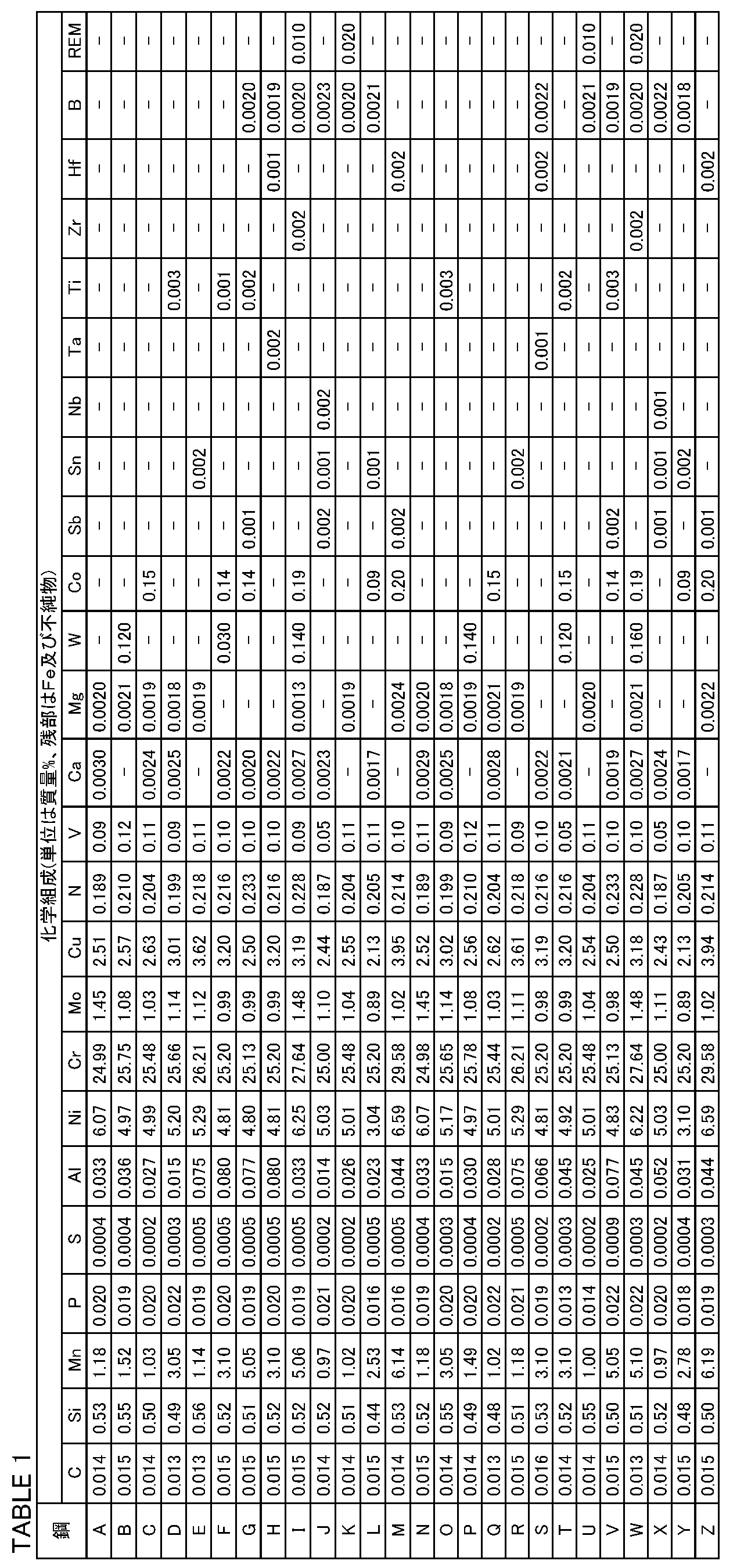
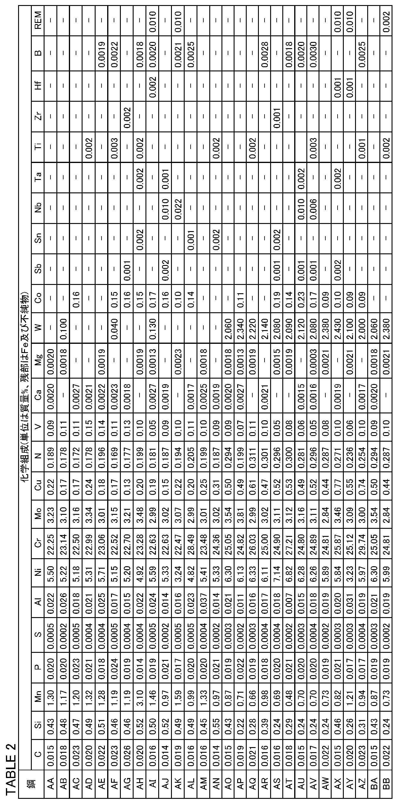

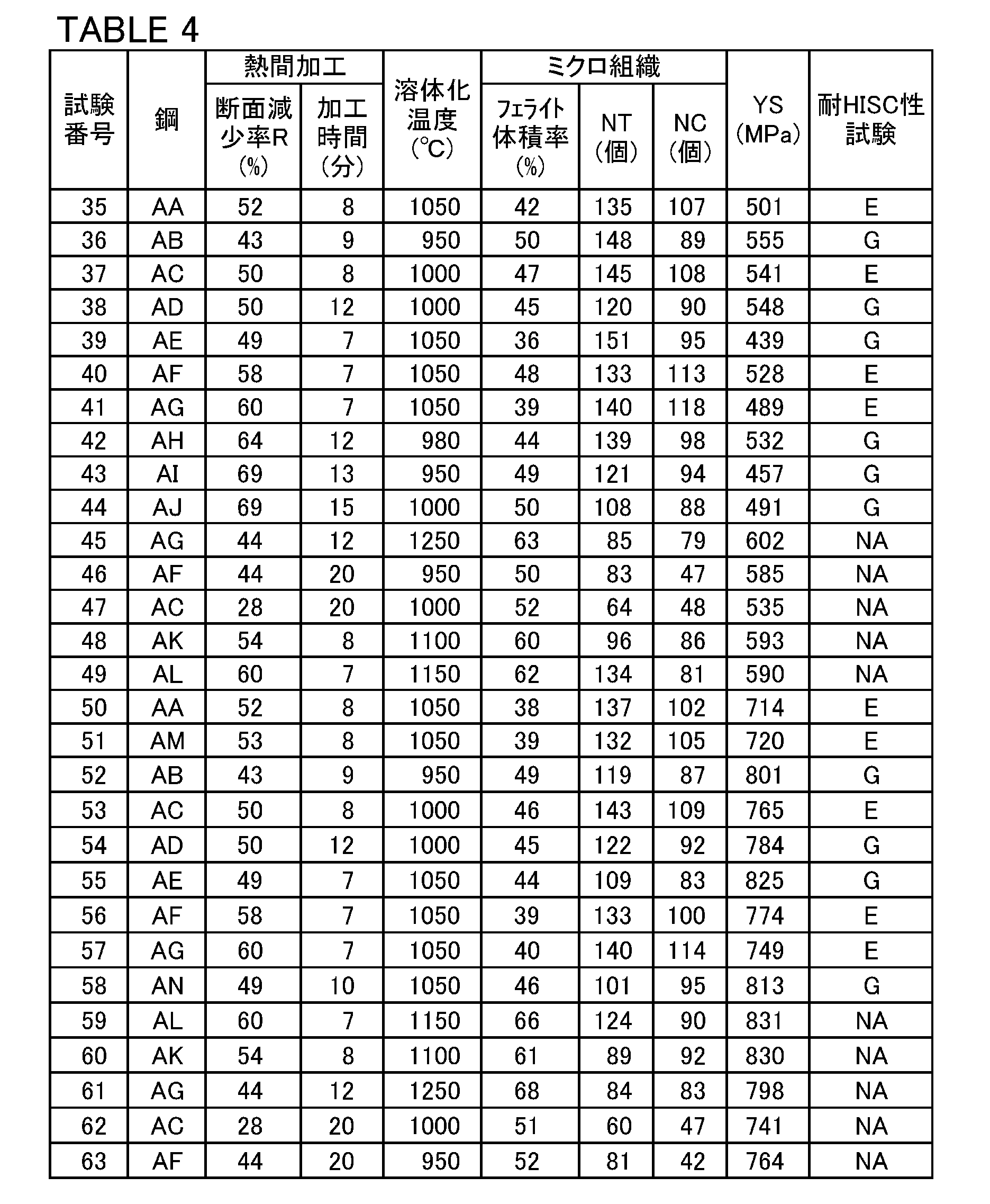
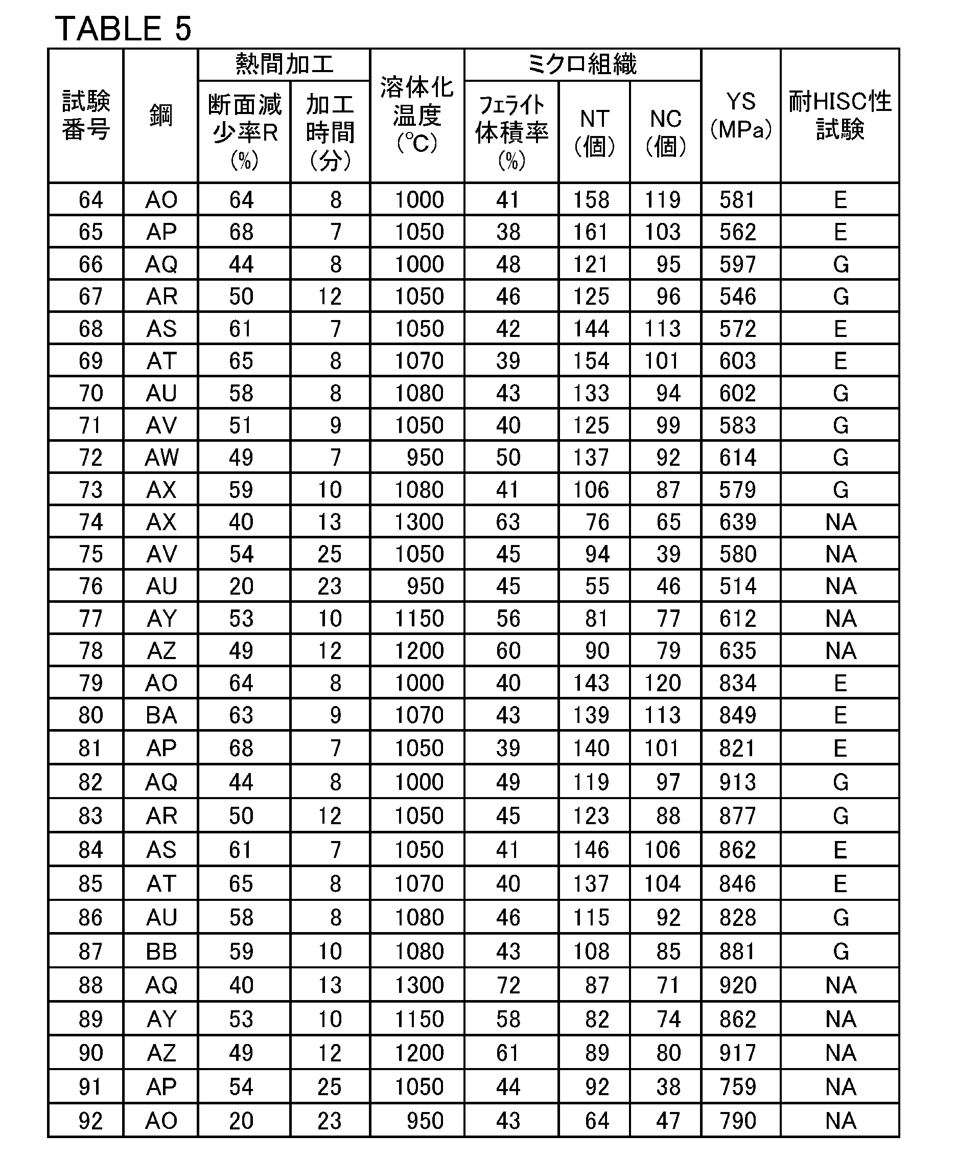
上記のとおりに製造された各試験番号の継目無鋼管に対して、以下に説明するミクロ組織観察と、引張試験と、耐HISC性試験とを実施した。
各試験番号の継目無鋼管に対して、ミクロ組織観察を実施して、フェライトの体積率と、250μm×250μmの観察視野における、T方向の交点数NT及びC方向の交点数NCとを求めた。具体的には、各試験番号の継目無鋼管の肉厚中央部から、C方向:5mm×T方向:5mmの観察面を有するミクロ組織観察用の試験片を作製した。各試験番号の試験片の観察面を、鏡面に研磨した。鏡面研磨された観察面を7%水酸化カリウム腐食液中で電解腐食し組織現出を行った。組織現出された観察面を、光学顕微鏡を用いて10視野観察した。各視野の面積は、6.25×104μm2(250μm×250μm)であり、倍率は400倍であった。
各試験番号の継目無鋼管に対して、ASTM E8/E8M(2013)に準拠した上述の方法で引張試験を実施して、降伏強度(MPa)を求めた。本実施例では、引張試験用の丸棒試験片は、各試験番号の継目無鋼管の肉厚中央部から作製した。丸棒試験片の大きさは、平行部直径6mm、平行部長さ30mmであった。なお、丸棒試験片の軸方向は、継目無鋼管の管軸方向(L方向)と平行であった。引張試験で得られた0.2%オフセット耐力を、降伏強度(MPa)とした。各試験番号の降伏強度を「YS(MPa)」として表3~表5に示す。
各試験番号の継目無鋼管に対して、耐HISC性試験を実施して、耐HISC性を評価した。具体的には、各試験番号の継目無鋼管の肉厚中央部から、耐HISC性試験用のVノッチ試験片を作製した。Vノッチ試験片は、平行部の断面が一辺7.5mmの矩形であり、平行部長さが25.4mmであった。Vノッチ試験片の長手方向は、継目無鋼管の管軸方向(L方向)と平行であった。さらに、Vノッチ試験片の平行部では、長手方向の中央位置のうち、継目無鋼管の表面側に相当する位置に、向き管径方向(C方向)、角度45°、深さ1.5mmのVノッチが形成された。
表3~表5に試験結果を示す。表1~表5を参照して、試験番号1~11、18~28、35~44、50~58、64~73、及び、79~87の継目無鋼管はいずれも、化学組成が適切であった。さらに、製造方法も明細書に記載の好ましい製造方法であった。その結果、フェライトの体積率が30~55%であった。さらに、250μm×250μmの観察視野領域における、交点数NTが65個以上であり、交点数NCが50個以上であった。さらに、降伏強度が415MPa以上であった。その結果、耐HISC性試験において優れた耐HISC性を示した。
20 オーステナイト
50 観察視野領域
Claims (2)
- 二相ステンレス継目無鋼管であって、
質量%で、
C:0.030%以下、
Si:0.20~1.00%、
Mn:0.10~7.00%、
P:0.040%以下、
S:0.0100%以下、
Al:0.100%以下、
Ni:4.00~9.00%、
Cr:20.00~28.00%、
Mo:0.50~5.00%、
Cu:0.01~4.00%、
N:0.050~0.500%、
V:0.01~1.50%、
W:0~4.000%、
Co:0~2.00%、
Sb:0~0.100%、
Sn:0~0.100%、
Nb:0~0.100%、
Ta:0~0.100%、
Ti:0~0.100%、
Zr:0~0.100%、
Hf:0~0.100%、
B:0~0.0200%、及び、
希土類元素:0~0.200%を含有し、
Ca:0.0001~0.0200%、及び、
Mg:0.0001~0.0200%からなる群から選択される1元素以上を含有し、
残部がFe及び不純物からなり、
ミクロ組織が、体積率で30~55%のフェライト及びオーステナイトからなり、
降伏強度が、415MPa以上であり、
前記二相ステンレス継目無鋼管の管軸方向をL方向、前記二相ステンレス継目無鋼管の管径方向をT方向、前記L方向及び前記T方向と垂直な方向をC方向と定義したとき、
前記二相ステンレス継目無鋼管の肉厚中央部を含み、前記T方向に延びる辺の長さが250μmであり、前記C方向に延びる辺の長さが250μmである正方形の観察視野領域において、
前記T方向に延びる線分であって、前記観察視野領域の前記C方向に等間隔に配列され、前記観察視野領域を前記C方向に5等分する4つの線分をT1~T4と定義し、
前記C方向に延びる線分であって、前記観察視野領域の前記T方向に等間隔に配列され、前記観察視野領域を前記T方向に5等分する4つの線分をC1~C4と定義し、
前記観察視野領域における前記フェライトと前記オーステナイトとの界面をフェライト界面と定義したとき、
前記線分T1~T4と前記フェライト界面との交点の数である交点数NTが65個以上であり、
前記線分C1~C4と前記フェライト界面との交点の数である交点数NCが50個以上である、
二相ステンレス継目無鋼管。 - 請求項1に記載の二相ステンレス継目無鋼管であって、
W:0.001~4.000%、
Co:0.01~2.00%、
Sb:0.001~0.100%、
Sn:0.001~0.100%、
Nb:0.001~0.100%、
Ta:0.001~0.100%、
Ti:0.001~0.100%、
Zr:0.001~0.100%、
Hf:0.001~0.100%、
B:0.0005~0.0200%、及び、
希土類元素:0.001~0.200%からなる群から選択される1元素以上を含有する、
二相ステンレス継目無鋼管。
Priority Applications (7)
| Application Number | Priority Date | Filing Date | Title |
|---|---|---|---|
| US17/995,636 US12522905B2 (en) | 2020-05-07 | 2021-04-28 | Duplex stainless steel seamless pipe |
| JP2022519940A JP7477790B2 (ja) | 2020-05-07 | 2021-04-28 | 二相ステンレス継目無鋼管 |
| CN202180032950.0A CN115485406B (zh) | 2020-05-07 | 2021-04-28 | 双相不锈钢无缝钢管 |
| EP21800455.4A EP4148158A4 (en) | 2020-05-07 | 2021-04-28 | DUPLEX STAINLESS STEEL SEAMLESS PIPE |
| BR112022021372-7A BR112022021372B1 (pt) | 2020-05-07 | 2021-04-28 | Tubo duplex de aço inoxidável sem costura |
| CA3175342A CA3175342A1 (en) | 2020-05-07 | 2021-04-28 | Duplex stainless steel seamless pipe |
| MX2022013446A MX2022013446A (es) | 2020-05-07 | 2021-04-28 | Tubo sin costura de acero inoxidable duplex. |
Applications Claiming Priority (6)
| Application Number | Priority Date | Filing Date | Title |
|---|---|---|---|
| JP2020081917 | 2020-05-07 | ||
| JP2020-081833 | 2020-05-07 | ||
| JP2020-082042 | 2020-05-07 | ||
| JP2020082042 | 2020-05-07 | ||
| JP2020081833 | 2020-05-07 | ||
| JP2020-081917 | 2020-05-07 |
Publications (1)
| Publication Number | Publication Date |
|---|---|
| WO2021225103A1 true WO2021225103A1 (ja) | 2021-11-11 |
Family
ID=78468098
Family Applications (1)
| Application Number | Title | Priority Date | Filing Date |
|---|---|---|---|
| PCT/JP2021/016954 Ceased WO2021225103A1 (ja) | 2020-05-07 | 2021-04-28 | 二相ステンレス継目無鋼管 |
Country Status (7)
| Country | Link |
|---|---|
| US (1) | US12522905B2 (ja) |
| EP (1) | EP4148158A4 (ja) |
| JP (1) | JP7477790B2 (ja) |
| CN (1) | CN115485406B (ja) |
| CA (1) | CA3175342A1 (ja) |
| MX (1) | MX2022013446A (ja) |
| WO (1) | WO2021225103A1 (ja) |
Cited By (6)
| Publication number | Priority date | Publication date | Assignee | Title |
|---|---|---|---|---|
| WO2024043259A1 (ja) * | 2022-08-24 | 2024-02-29 | 日本製鉄株式会社 | 二相ステンレス鋼材 |
| JPWO2025018103A1 (ja) * | 2023-07-18 | 2025-01-23 | ||
| WO2025187217A1 (ja) * | 2024-03-05 | 2025-09-12 | Jfeスチール株式会社 | ステンレス鋼管および油井管 |
| WO2025215951A1 (ja) * | 2024-04-10 | 2025-10-16 | 日本製鉄株式会社 | 二相ステンレス継目無鋼管 |
| RU2854812C2 (ru) * | 2022-08-24 | 2026-01-19 | Ниппон Стиил Корпорейшн | Материал из дуплексной нержавеющей стали |
| EP4606918A4 (en) * | 2022-10-18 | 2026-04-15 | Nippon Steel Corp | DUPLEX STAINLESS STEEL MATERIAL |
Families Citing this family (1)
| Publication number | Priority date | Publication date | Assignee | Title |
|---|---|---|---|---|
| JP7553883B1 (ja) * | 2023-03-17 | 2024-09-19 | 日本製鉄株式会社 | 二相ステンレス鋼管 |
Citations (8)
| Publication number | Priority date | Publication date | Assignee | Title |
|---|---|---|---|---|
| JPH05132741A (ja) | 1991-11-11 | 1993-05-28 | Sumitomo Metal Ind Ltd | 耐食性に優れた高強度二相ステンレス鋼 |
| JPH09195003A (ja) | 1996-01-08 | 1997-07-29 | Sumitomo Metal Mining Co Ltd | 二相ステンレス鋼 |
| JP2014043616A (ja) | 2012-08-27 | 2014-03-13 | Nippon Steel & Sumitomo Metal | 二相ステンレス鋼およびその製造方法 |
| JP2016003377A (ja) | 2014-06-18 | 2016-01-12 | 新日鐵住金株式会社 | 二相ステンレス鋼管 |
| JP2016117944A (ja) * | 2014-12-18 | 2016-06-30 | Jfeスチール株式会社 | 二相ステンレス継目無鋼管の製造方法 |
| JP2016164288A (ja) * | 2015-03-06 | 2016-09-08 | Jfeスチール株式会社 | 油井用高強度ステンレス継目無鋼管の製造方法 |
| WO2020013197A1 (ja) * | 2018-07-09 | 2020-01-16 | 日本製鉄株式会社 | 継目無鋼管及びその製造方法 |
| WO2020218426A1 (ja) * | 2019-04-24 | 2020-10-29 | 日本製鉄株式会社 | 二相ステンレス継目無鋼管、及び、二相ステンレス継目無鋼管の製造方法 |
Family Cites Families (7)
| Publication number | Priority date | Publication date | Assignee | Title |
|---|---|---|---|---|
| JP4824640B2 (ja) | 2007-06-28 | 2011-11-30 | 日本冶金工業株式会社 | 二相ステンレス鋼およびその製造方法 |
| JP4911266B2 (ja) * | 2010-04-28 | 2012-04-04 | 住友金属工業株式会社 | 高強度油井用ステンレス鋼及び高強度油井用ステンレス鋼管 |
| JP2017095794A (ja) * | 2015-11-17 | 2017-06-01 | 株式会社神戸製鋼所 | 二相ステンレス鋼材および二相ステンレス鋼管 |
| JP6693561B2 (ja) * | 2016-06-01 | 2020-05-13 | 日本製鉄株式会社 | 二相ステンレス鋼及び二相ステンレス鋼の製造方法 |
| CN109642282B (zh) * | 2016-09-02 | 2021-10-01 | 杰富意钢铁株式会社 | 双相不锈钢及其制造方法 |
| WO2018131412A1 (ja) * | 2017-01-10 | 2018-07-19 | Jfeスチール株式会社 | 二相ステンレス鋼およびその製造方法 |
| WO2020044988A1 (ja) * | 2018-08-31 | 2020-03-05 | Jfeスチール株式会社 | 二相ステンレス継目無鋼管およびその製造方法 |
-
2021
- 2021-04-28 EP EP21800455.4A patent/EP4148158A4/en active Pending
- 2021-04-28 CA CA3175342A patent/CA3175342A1/en active Pending
- 2021-04-28 JP JP2022519940A patent/JP7477790B2/ja active Active
- 2021-04-28 US US17/995,636 patent/US12522905B2/en active Active
- 2021-04-28 MX MX2022013446A patent/MX2022013446A/es unknown
- 2021-04-28 WO PCT/JP2021/016954 patent/WO2021225103A1/ja not_active Ceased
- 2021-04-28 CN CN202180032950.0A patent/CN115485406B/zh active Active
Patent Citations (8)
| Publication number | Priority date | Publication date | Assignee | Title |
|---|---|---|---|---|
| JPH05132741A (ja) | 1991-11-11 | 1993-05-28 | Sumitomo Metal Ind Ltd | 耐食性に優れた高強度二相ステンレス鋼 |
| JPH09195003A (ja) | 1996-01-08 | 1997-07-29 | Sumitomo Metal Mining Co Ltd | 二相ステンレス鋼 |
| JP2014043616A (ja) | 2012-08-27 | 2014-03-13 | Nippon Steel & Sumitomo Metal | 二相ステンレス鋼およびその製造方法 |
| JP2016003377A (ja) | 2014-06-18 | 2016-01-12 | 新日鐵住金株式会社 | 二相ステンレス鋼管 |
| JP2016117944A (ja) * | 2014-12-18 | 2016-06-30 | Jfeスチール株式会社 | 二相ステンレス継目無鋼管の製造方法 |
| JP2016164288A (ja) * | 2015-03-06 | 2016-09-08 | Jfeスチール株式会社 | 油井用高強度ステンレス継目無鋼管の製造方法 |
| WO2020013197A1 (ja) * | 2018-07-09 | 2020-01-16 | 日本製鉄株式会社 | 継目無鋼管及びその製造方法 |
| WO2020218426A1 (ja) * | 2019-04-24 | 2020-10-29 | 日本製鉄株式会社 | 二相ステンレス継目無鋼管、及び、二相ステンレス継目無鋼管の製造方法 |
Non-Patent Citations (1)
| Title |
|---|
| See also references of EP4148158A4 |
Cited By (11)
| Publication number | Priority date | Publication date | Assignee | Title |
|---|---|---|---|---|
| WO2024043259A1 (ja) * | 2022-08-24 | 2024-02-29 | 日本製鉄株式会社 | 二相ステンレス鋼材 |
| JPWO2024043259A1 (ja) * | 2022-08-24 | 2024-02-29 | ||
| RU2854812C2 (ru) * | 2022-08-24 | 2026-01-19 | Ниппон Стиил Корпорейшн | Материал из дуплексной нержавеющей стали |
| EP4606918A4 (en) * | 2022-10-18 | 2026-04-15 | Nippon Steel Corp | DUPLEX STAINLESS STEEL MATERIAL |
| JPWO2025018103A1 (ja) * | 2023-07-18 | 2025-01-23 | ||
| WO2025018103A1 (ja) * | 2023-07-18 | 2025-01-23 | Jfeスチール株式会社 | 二相ステンレス鋼およびステンレス継目無鋼管 |
| JP7816551B2 (ja) | 2023-07-18 | 2026-02-18 | Jfeスチール株式会社 | 二相ステンレス鋼およびステンレス継目無鋼管 |
| WO2025187217A1 (ja) * | 2024-03-05 | 2025-09-12 | Jfeスチール株式会社 | ステンレス鋼管および油井管 |
| JP7800781B1 (ja) * | 2024-03-05 | 2026-01-16 | Jfeスチール株式会社 | ステンレス鋼管および油井管 |
| WO2025215951A1 (ja) * | 2024-04-10 | 2025-10-16 | 日本製鉄株式会社 | 二相ステンレス継目無鋼管 |
| JP7769284B1 (ja) * | 2024-04-10 | 2025-11-13 | 日本製鉄株式会社 | 二相ステンレス継目無鋼管 |
Also Published As
| Publication number | Publication date |
|---|---|
| CA3175342A1 (en) | 2021-11-11 |
| US20230212723A1 (en) | 2023-07-06 |
| JP7477790B2 (ja) | 2024-05-02 |
| JPWO2021225103A1 (ja) | 2021-11-11 |
| MX2022013446A (es) | 2022-11-16 |
| EP4148158A4 (en) | 2023-11-15 |
| EP4148158A1 (en) | 2023-03-15 |
| CN115485406B (zh) | 2023-12-19 |
| US12522905B2 (en) | 2026-01-13 |
| CN115485406A (zh) | 2022-12-16 |
| BR112022021372A2 (pt) | 2022-12-06 |
Similar Documents
| Publication | Publication Date | Title |
|---|---|---|
| JP7518342B2 (ja) | 二相ステンレス鋼材 | |
| JP7477790B2 (ja) | 二相ステンレス継目無鋼管 | |
| JP4911266B2 (ja) | 高強度油井用ステンレス鋼及び高強度油井用ステンレス鋼管 | |
| JP7173359B2 (ja) | 二相ステンレス鋼材 | |
| JP6946737B2 (ja) | 二相ステンレス鋼材及びその製造方法 | |
| JP7425360B2 (ja) | マルテンサイト系ステンレス鋼材、及び、マルテンサイト系ステンレス鋼材の製造方法 | |
| JP7518343B2 (ja) | 二相ステンレス鋼材 | |
| WO2020067247A1 (ja) | マルテンサイトステンレス鋼材 | |
| JP6372070B2 (ja) | フェライト・マルテンサイト二相鋼及び油井用鋼管 | |
| US12385118B2 (en) | Duplex stainless seamless steel pipe and method for producing duplex stainless seamless steel pipe | |
| WO2021039431A1 (ja) | サワー環境での使用に適した鋼材 | |
| JP7498420B1 (ja) | 二相ステンレス鋼材 | |
| JP7364955B1 (ja) | 二相ステンレス鋼材 | |
| JP2025110947A (ja) | ステンレス鋼材 | |
| WO2024063108A1 (ja) | マルテンサイト系ステンレス鋼材 | |
| JP2020186441A (ja) | 2相ステンレス鋼 | |
| WO2023162817A1 (ja) | 二相ステンレス鋼材 | |
| WO2023195495A1 (ja) | 鋼材 | |
| JP7256435B1 (ja) | 二相ステンレス鋼材 | |
| JP7678375B1 (ja) | ステンレス鋼材 | |
| JP7553883B1 (ja) | 二相ステンレス鋼管 | |
| JP7381983B2 (ja) | マルテンサイト系ステンレス継目無鋼管、及び、マルテンサイト系ステンレス継目無鋼管の製造方法 | |
| JP7323858B1 (ja) | 二相ステンレス鋼材 | |
| JP7364993B1 (ja) | 鋼材 | |
| WO2024195730A1 (ja) | 二相ステンレス鋼管 |
Legal Events
| Date | Code | Title | Description |
|---|---|---|---|
| 121 | Ep: the epo has been informed by wipo that ep was designated in this application |
Ref document number: 21800455 Country of ref document: EP Kind code of ref document: A1 |
|
| ENP | Entry into the national phase |
Ref document number: 2022519940 Country of ref document: JP Kind code of ref document: A |
|
| ENP | Entry into the national phase |
Ref document number: 3175342 Country of ref document: CA |
|
| REG | Reference to national code |
Ref country code: BR Ref legal event code: B01A Ref document number: 112022021372 Country of ref document: BR |
|
| ENP | Entry into the national phase |
Ref document number: 112022021372 Country of ref document: BR Kind code of ref document: A2 Effective date: 20221020 |
|
| NENP | Non-entry into the national phase |
Ref country code: DE |
|
| ENP | Entry into the national phase |
Ref document number: 2021800455 Country of ref document: EP Effective date: 20221207 |
|
| WWG | Wipo information: grant in national office |
Ref document number: 17995636 Country of ref document: US |