WO2021225121A1 - スプリングコネクタ - Google Patents
スプリングコネクタ Download PDFInfo
- Publication number
- WO2021225121A1 WO2021225121A1 PCT/JP2021/017237 JP2021017237W WO2021225121A1 WO 2021225121 A1 WO2021225121 A1 WO 2021225121A1 JP 2021017237 W JP2021017237 W JP 2021017237W WO 2021225121 A1 WO2021225121 A1 WO 2021225121A1
- Authority
- WO
- WIPO (PCT)
- Prior art keywords
- winding
- winding portion
- eccentric
- coil spring
- spring connector
- Prior art date
- Legal status (The legal status is an assumption and is not a legal conclusion. Google has not performed a legal analysis and makes no representation as to the accuracy of the status listed.)
- Ceased
Links
Images


Classifications
-
- H—ELECTRICITY
- H01—ELECTRIC ELEMENTS
- H01R—ELECTRICALLY-CONDUCTIVE CONNECTIONS; STRUCTURAL ASSOCIATIONS OF A PLURALITY OF MUTUALLY-INSULATED ELECTRICAL CONNECTING ELEMENTS; COUPLING DEVICES; CURRENT COLLECTORS
- H01R13/00—Details of coupling devices of the kinds covered by groups H01R12/70 or H01R24/00 - H01R33/00
- H01R13/02—Contact members
- H01R13/22—Contacts for co-operating by abutting
- H01R13/24—Contacts for co-operating by abutting resilient; resiliently-mounted
- H01R13/2407—Contacts for co-operating by abutting resilient; resiliently-mounted characterized by the resilient means
- H01R13/2421—Contacts for co-operating by abutting resilient; resiliently-mounted characterized by the resilient means using coil springs
-
- H—ELECTRICITY
- H01—ELECTRIC ELEMENTS
- H01R—ELECTRICALLY-CONDUCTIVE CONNECTIONS; STRUCTURAL ASSOCIATIONS OF A PLURALITY OF MUTUALLY-INSULATED ELECTRICAL CONNECTING ELEMENTS; COUPLING DEVICES; CURRENT COLLECTORS
- H01R4/00—Electrically-conductive connections between two or more conductive members in direct contact, i.e. touching one another; Means for effecting or maintaining such contact; Electrically-conductive connections having two or more spaced connecting locations for conductors and using contact members penetrating insulation
- H01R4/28—Clamped connections, spring connections
- H01R4/48—Clamped connections, spring connections utilising a spring, clip, or other resilient member
- H01R4/4854—Clamped connections, spring connections utilising a spring, clip, or other resilient member using a wire spring
- H01R4/4863—Coil spring
-
- F—MECHANICAL ENGINEERING; LIGHTING; HEATING; WEAPONS; BLASTING
- F16—ENGINEERING ELEMENTS AND UNITS; GENERAL MEASURES FOR PRODUCING AND MAINTAINING EFFECTIVE FUNCTIONING OF MACHINES OR INSTALLATIONS; THERMAL INSULATION IN GENERAL
- F16F—SPRINGS; SHOCK-ABSORBERS; MEANS FOR DAMPING VIBRATION
- F16F1/00—Springs
- F16F1/02—Springs made of steel or other material having low internal friction; Wound, torsion, leaf, cup, ring or the like springs, the material of the spring not being relevant
- F16F1/04—Wound springs
- F16F1/06—Wound springs with turns lying in cylindrical surfaces
-
- H—ELECTRICITY
- H01—ELECTRIC ELEMENTS
- H01R—ELECTRICALLY-CONDUCTIVE CONNECTIONS; STRUCTURAL ASSOCIATIONS OF A PLURALITY OF MUTUALLY-INSULATED ELECTRICAL CONNECTING ELEMENTS; COUPLING DEVICES; CURRENT COLLECTORS
- H01R13/00—Details of coupling devices of the kinds covered by groups H01R12/70 or H01R24/00 - H01R33/00
- H01R13/02—Contact members
- H01R13/22—Contacts for co-operating by abutting
- H01R13/24—Contacts for co-operating by abutting resilient; resiliently-mounted
- H01R13/2464—Contacts for co-operating by abutting resilient; resiliently-mounted characterized by the contact point
- H01R13/2471—Contacts for co-operating by abutting resilient; resiliently-mounted characterized by the contact point pin shaped
-
- H—ELECTRICITY
- H01—ELECTRIC ELEMENTS
- H01R—ELECTRICALLY-CONDUCTIVE CONNECTIONS; STRUCTURAL ASSOCIATIONS OF A PLURALITY OF MUTUALLY-INSULATED ELECTRICAL CONNECTING ELEMENTS; COUPLING DEVICES; CURRENT COLLECTORS
- H01R4/00—Electrically-conductive connections between two or more conductive members in direct contact, i.e. touching one another; Means for effecting or maintaining such contact; Electrically-conductive connections having two or more spaced connecting locations for conductors and using contact members penetrating insulation
- H01R4/58—Electrically-conductive connections between two or more conductive members in direct contact, i.e. touching one another; Means for effecting or maintaining such contact; Electrically-conductive connections having two or more spaced connecting locations for conductors and using contact members penetrating insulation characterised by the form or material of the contacting members
- H01R4/60—Connections between or with tubular conductors
Definitions
- the present invention relates to a spring connector.
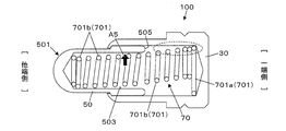
- FIG. 13 is a diagram showing a configuration example of a conventional spring connector 100, and is an end view of a tube 30, a movable pin 50, and a coil spring 70 that vertically traverse the spring connector 100.
- FIG. 14 is a diagram for explaining the configuration of the coil spring 70 in the free state removed from the spring connector 100, and is an end view of one end side of the coil spring 70 that abuts on the bottom of the tube 30.
- the spring connector 100 includes a bottomed tube 30, a movable pin 50, and a coil spring 70.
- the movable pin 50 has a hole 503 in which the tip 501 projects from the opening of the tube 30 and opens in the direction opposite to the protruding direction.
- One end of the coil spring 70 abuts on the bottom of the tube 30, and the other end abuts on the bottom of the hole 503 to urge the movable pin 50 in the protruding direction.
- the coil spring 70 has a plurality of winding portions 701 (701a, 701b). As shown in FIG. 14, the winding portion 701a related to one end portion in contact with the bottom portion of the tube 30 has a larger diameter than the other winding portions 701b. In the free state of the winding portion 701a, the winding center of the other winding portion 701b (indicated by the alternate long and short dash line) is eccentrically arranged with respect to the winding center (indicated by the dotted line) of the winding portion 701a related to one end portion. It is composed of. On the other hand, as shown in FIG. 13, the tube 30 has an inner diameter into which a large-diameter winding portion 701a can be inserted.
- the hole portion of the movable pin 50 has an inner diameter such that a large-diameter winding portion 701a cannot be inserted and only the winding portion 701b can be inserted.
- the center of the bottom of the tube 30 and the center of the bottom of the hole 503 of the movable pin 50 are located on the central axis of the spring connector 100. Therefore, the coil spring 70 housed in the spring connector 100 is at a position where the winding portion 701b near one end is eccentric from the central axis. Further, the winding portion 701b near the other end portion that abuts on the bottom portion of the hole portion 503 is on the central axis or at a position close to the central axis.
- the coil spring 70 is housed in the spring connector 100 in a curved shape in which the winding center of each winding portion 701 is gradually displaced as a whole.
- the winding portion 701a related to one end portion has a large diameter
- the winding portion 701b other than the winding portion 701a is eccentrically arranged with respect to the winding portion 701a. Therefore, the winding portion 701b on one end side close to the winding portion 701a is located in the tube 30, but is located close to the inner peripheral surface of the tube 30.
- the winding portion 701b on one end side close to the winding portion 701a is located in the space behind the rear end surface 505 of the movable pin 50 (in the direction of being pushed in during use).
- the winding portions 701a and 701b on one end side may hinder the movement of the movable pin 50 in the retracting direction. This can impair the contact stability between the movable pin 50 and the tube 30.
- An example of an object of the present invention is to provide a technique capable of improving contact stability between a movable pin and a tube.
- One aspect of the present invention includes a tube, a movable pin having a hole whose tip protrudes from the opening of the tube and opens on the side opposite to the protruding direction, and a coil spring that urges the movable pin in the protruding direction.
- the coil spring is eccentric with the winding center eccentric with respect to the axial straight line connecting the winding center of the winding portion related to one end and the winding center of the winding portion related to the other end.
- a spring connector having a winding portion.
- the coil spring of the spring connector of the present embodiment is configured to have an eccentric winding portion in the effective number of winding portions between the winding portions related to both ends thereof.
- the eccentric winding portion is a portion where the winding center is eccentric with respect to the axial straight line connecting the winding centers of the winding portions related to both ends.
- the winding portion on one end side of the coil spring does not hinder the movement of the movable pin. Therefore, the moving range of the movable pin at the time of use can be widened, and the total length of the spring connector can be shortened accordingly. In addition, the contact stability between the movable pin and the tube can be improved.
- FIGS. 1 and 2 are views showing a configuration example of the spring connector 10 according to the first embodiment.
- 1 and 2 are views in which the tube 3 and the movable pin 5 are cut out so as to traverse the spring connector 10, and the end face of the tube 3 and the movable pin 5 and the side surface of the coil spring 7 are shown.
- FIG. 1 shows a state in which the movable pin 5 protrudes (protruding state)
- FIG. 2 shows a state in which the tip portion 511 of the movable pin 5 is pushed and retracted into the tube 3 (retracted state).
- the spring connector 10 of the first embodiment includes a bottomed tube 3, a movable pin 5, and a coil spring 7.
- the tip portion 511 of the movable pin 5 projects from the opening of the tube 3.
- the coil spring 7 urges the movable pin 5 in the protruding direction.
- the tube 3 is a bottomed cylindrical body made of a conductive material (for example, copper or a copper alloy), and holds the movable pin 5 slidably on the other end side of the opening.
- the open end of the tube 3 is bent inward by caulking to form a locking portion 31, which prevents the movable pin 5 from coming off.
- the movable pin 5 is made of a conductive material (for example, copper or a copper alloy).
- the movable pin 5 is composed of a small diameter portion 51 and a large diameter portion 53 having an outer diameter larger than that of the small diameter portion 51, and has a hole portion 55 that opens on the side opposite to the protruding direction (one end side).
- the inner diameters of the small diameter portion 51 and the large diameter portion 53 are the same.
- a hole portion 55 having a constant inner diameter is defined by the inner peripheral surface of the small diameter portion 51 and the inner peripheral surface of the large diameter portion 53.
- the tip portion 511 which is the tip of the small diameter portion 51, serves as a contact portion that comes into contact with the terminal to be contacted.
- the small diameter portion 51 and the large diameter portion 53 are connected by a stepped portion having an outer diameter, and the tapered stepped surface 57 between the two is in contact with the locking portion 31 of the tube 3, and the movable pin 5 is formed. It is configured to prevent it from coming off the tube 3. Therefore, the large diameter portion 53 is located in the tube 3 even when the small diameter portion 51 protrudes from the tube 3.
- the coil spring 7 is a coil spring having closed ends at both ends, wherein the winding portion related to both ends 711 and 731 is a countersunk portion.
- the coil spring 7 is made of, for example, a piano wire or a stainless steel wire.
- the coil spring 7 may be made of an insulating material or may be coated with an insulating film.
- one end portion 711 abuts on the bottom portion of the tube 3, and the other end portion 731 abuts on the bottom portion of the hole portion 55 to urge the movable pin 5 in the protruding direction.
- FIG. 3 is an explanatory diagram illustrating the configuration of the coil spring 7.
- FIG. 3 is a side view in which only the coil spring 7 is extracted from the protruding spring connector 10 shown in FIG.
- the coil spring 7 has an effective winding number portion between the end winding portion 71 related to the one end portion 711, the end winding portion 73 related to the other end portion 731, and the one end portion 711 and the other end portion 731. It is composed of 75 and.
- the countersunk portion 71 is hereinafter appropriately referred to as a “one-sided counterbore portion”.
- the end turn portion 73 is hereinafter appropriately referred to as “the other end end winding portion”.
- the effective number of turns portion 75 has a plurality of winding portions 751 (751a, 751b).
- the portion corresponding to one pitch L2 corresponds to one winding portion 751.
- the winding portion 751 of the effective winding portion 75 is an eccentric winding in which the winding center is eccentric with respect to the axial straight line L1 connecting the winding center of the one end end winding portion 71 and the winding center of the other end end winding portion 73.
- the winding portion 751b is hereinafter appropriately referred to as a “non-eccentric winding portion”.
- one of the winding portions 751 of the effective winding portion 75 is an eccentric winding portion 751a.
- the eccentric winding portion 751a is located inside the hole portion 55 in FIGS. 1 and 2, it may be provided outside the hole portion 55. In this case, when the coil spring 7 itself is pushed and bent, a part of the winding portion 751b located inside the hole portion 55 pushes the inner side surface of the pin to apply lateral pressure.
- the outer diameter of the eccentric winding portion 751a is smaller than the outer diameter of the winding portion 751 (non-eccentric winding portion 751b) adjacent to the eccentric winding portion 751a.
- all the non-eccentric winding portions 751b have the same outer diameter, and the outer diameter of the eccentric winding portion 751a is determined as a smaller outer diameter.
- the eccentric winding portion 751a is provided at the entire length of the coil spring 7 or substantially at the center of the effective winding portion 75, but the position where the coil spring 7 is provided is not limited to this.
- the outer diameter of the one-sided end-winding portion 71 is smaller than the outer diameter of the winding portion 751 (non-eccentric winding portion 751b) adjacent to the one-ended end-winding portion 71.
- the outer diameter of the other end end winding portion 73 is smaller than the outer diameter of the winding portion 751 (non-eccentric winding portion 751b) adjacent to the other end end winding portion 73.
- the end end winding portion 71 and the other end end turn portion 73 have the same outer diameter, and the outer diameter is defined as an outer diameter smaller than that of the non-eccentric winding portion 751b.
- FIG. 4 is an explanatory diagram for explaining the positional condition of the one end portion 711.
- FIG. 4 schematically shows the positional relationship between the end end winding portion 71 and the eccentric winding portion 751a in a plan view of the one end portion 711 viewed from the linear direction of the axial straight line L1 of FIG.
- the winding of the end end winding portion 71 and the eccentric winding portion 751a is indicated by a circle, and the one end portion 711 is indicated by a large black circle as P35.
- the position of the axial straight line L1 is a position corresponding to the center of the end turn portion 71 at one end, and is indicated by the base point P31 of the black circle in FIG.
- the position of the one end portion 711 is determined based on the line (reference line) L31 from the base point P31 indicating the position of the axial straight line L1 to the winding center P33 of the eccentric winding portion 751a. Specifically, the position of the one end portion 711 is set so that the angle formed by the reference line L31 and the line from the base point P31 to the one end portion 711 is 90 degrees or more and 270 degrees or less in the clockwise direction. ..
- the position of the one end portion 711 is within the angle range indicated by hatching in FIG. 4 which is 90 degrees or more away from the direction of the eccentricity indicated by the arrow in FIG. 4 of the eccentric winding portion 751a. It is stipulated in.
- the positions of the one end portion 711 and the other end portion 731 are defined to be the positions P35 at which the angle formed by the reference line L31 is 180 degrees.
- the position P35 can be said to be a position 180 degrees away from the direction of eccentricity.
- the position of the other end 731 is also determined in the same manner. That is, the line from the base point indicating the position of the axial straight line L1 in the plan view of the other end portion 731 from the linear direction of the axial straight line L1 toward the winding center of the eccentric winding portion 751a is set as the reference line.
- the position of the other end portion 731 is determined as a position where the angle formed by the reference line and the line from the base point toward the other end portion 731 is 90 degrees or more and 270 degrees or less in the clockwise direction in the plan view.
- the action and effect regarding the positions of the one end portion 711 and the other end portion 731 will be described.
- the starting points at which the repulsive force is generated are one end 711 and the other end 731 of the coil spring 7.
- the positions of the one end portion 711 and the other end portion 731 are separated from the direction of the eccentricity indicated by the arrow in FIG. 4 of the eccentric winding portion 751a by more than 90 degrees.
- the circumference is 90 degrees or more and 270 degrees or less. Therefore, the repulsive force generated from the positions of the one end portion 711 and the other end portion 731 acts to move the eccentric winding portion 751a in the direction of the arrow A1 in FIG. 2 (eccentric direction).
- the coil spring 7 can be reliably bent by setting the positional relationship between the one end portion 711 and the other end portion 731 and the eccentric winding portion 751a as described above.
- the effects shown in FIG. 2 are exhibited.
- the movable pin 5 moves in the retracting direction and the coil spring 7 contracts.
- the coil spring 7 bends in the eccentric direction at the portion of the eccentric winding portion 751a.
- the eccentric direction is the direction indicated by the arrow A1 in FIG. 2, and is the direction in which the winding center of the eccentric winding portion 751a is eccentric with respect to the axial straight line L1 from the base point P31 in the plan view shown in FIG. This is the direction toward the winding center P33.
- a force in the eccentric direction acts to press the outer peripheral surface of the movable pin 5 (the outer peripheral portion of the hole portion 55) against the inner peripheral surface of the tube 3. Therefore, the movable pin 5 and the tube 3 can be surely brought into contact with each other during use, and a stable electrical connection between the movable pin 5 and the tube 3 can be realized. Even if the coil spring 7 contracts, the space behind the rear end surface 531 of the movable pin 5 (the direction in which the movable pin 5 is pushed) remains a space. Therefore, the portion on one end side of the coil spring 7 does not hinder the movement of the movable pin 5 in the retracting direction. Therefore, it is possible to provide a technique capable of improving the contact stability of the spring connector 10 without hindering the movement of the movable pin 5 during use.
- FIGS. 5 and 6 are views showing a configuration example of the spring connector 10a according to the second embodiment.
- 5 and 6 are views in which the tube 3 and the movable pin 5 are cut out so as to traverse the spring connector 10a, and the end surface of the tube 3 and the movable pin 5 and the side surface of the coil spring 7a are shown.
- FIG. 5 shows the protruding state of the movable pin 5
- FIG. 6 shows the retracted state of the movable pin 5.
- the spring connector 10a of the second embodiment includes a bottomed tube 3, a movable pin 5, and a coil spring 7a, as in the first embodiment.
- the movable pin 5 has a hole portion 55 in which the tip portion 511 protrudes from the opening of the tube 3 and opens in the direction opposite to the protruding direction.
- One end of the coil spring 7a abuts on the bottom of the tube 3 and the other end abuts on the bottom of the hole 55 to urge the movable pin 5 in the protruding direction.
- the coil spring 7a has a configuration in which the winding center of each winding portion 751 of the effective number of turns is gradually displaced as it approaches the eccentric winding portion 751a.
- the winding portion 751 located inside the hole portion 55, and the winding portion 751 near the center corresponds to the eccentric winding portion 751a.
- Each winding portion 751 other than the eccentric winding portion 751a is configured such that the winding center is displaced stepwise from both ends in the eccentric direction of the eccentric winding portion 751a.
- the coil spring 7a has a shape in which the longitudinal direction is bent in the eccentric direction as a whole.
- the arrangement of the eccentric winding portion 751a in the effective number of turns 75 of the coil spring is not limited to the arrangement illustrated in each of the above embodiments.
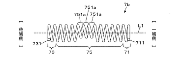
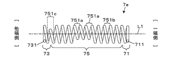
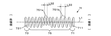
- 7 to 12 are diagrams showing the configurations of coil springs 7b, 7c, 7d, 7e, 7f, and 7g included in the spring connector of the modified example, respectively.
- the effective number of turns portion 75 may have a plurality of eccentric winding portions 751a.
- it has three eccentric winding portions 751a. According to this, it is possible to realize a coil spring 7b having a plurality of eccentric winding portions 751a in the effective number of turns portion 75.
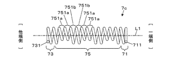
- the non-eccentric winding portion 751b and the eccentric winding portion 751a may be alternately arranged to form the effective number of turns portion 75.
- FIG. 8 shows a configuration example of the effective winding number portion 75 in which two non-eccentric winding portions 751b and two eccentric winding portions 751a are alternately arranged.
- the non-eccentric winding portion 751b and the eccentric winding portion 751a may be alternately arranged one by one. According to this, it is possible to realize the coil spring 7c in which the non-eccentric winding portion 751b and the eccentric winding portion 751a are alternately arranged in the effective number of turns portion 75.
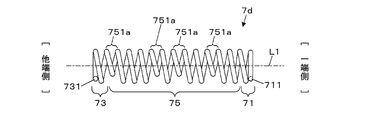
- the eccentric winding portion 751a in the effective number of turns portion 75 may be arranged irregularly. According to this, it is possible to realize the coil spring 7d in which the eccentric winding portion 751a is irregularly arranged in the effective winding number portion 75.
- the effective number of turns portion 75 may have a heterogeneous eccentric winding portion 751c in addition to the non-eccentric winding portion 751b and the eccentric winding portion 751a.
- the heterogeneous eccentric winding portion 751c is eccentrically wound from a base point indicating the position of the axial straight line L1 in a plan view (see FIG. 4) when one end portion 711 or the other end portion 731 of the coil spring is viewed from the linear direction of the axial straight line L1.
- the winding center is formed at a position where the angle formed by the line (reference line) L31 and the line from the base point P31 toward the winding center of the heterogeneous eccentric winding portion 751c is 90 degrees or less.
- the winding portion having the above is a heterogeneous eccentric winding portion 751c.
- the line (reference line) L31 is a line from the base point P31 indicating the position of the axial straight line L1 to the winding center P33 of the eccentric winding portion 751a.
- the effective number of turns portion 75 includes one heterogeneous eccentric winding portion 751c having a winding center in a direction opposite to the direction from the base point toward the winding center of the eccentric winding portion 751a. .. According to this, in the effective number of turns portion 75, it is possible to realize a coil spring 7e having a heterogeneous eccentric winding portion 751c eccentric with respect to the axial straight line L1 in a direction different from the direction in which the eccentric winding portion 751a is located.
- the pitch of the coil spring 7f may be an unequal pitch.
- the pitch L32 of the eccentric winding portion 751a may be narrower than the pitch L33 of the non-eccentric winding portion 751b.
- the pitch L32 of the eccentric winding portion 751a may be wider than the pitch L33 of the non-eccentric winding portion 751b.
- the spring connector can be configured by using the coil springs 7f having unequal pitches.
- the effective number of turns of the coil spring may include winding parts having different outer diameters.
- each winding The outer diameter of the portion 751 may also be gradually reduced as it approaches the eccentric winding portion 751a. According to this, it is possible to realize a coil spring 7g having a winding portion 751 having a different outer diameter in the effective winding number portion 75.
- a coil spring having closed ends at both ends in which the winding portion related to both ends is a countersunk portion, is illustrated, but a configuration using coil springs at both ends is used.
- the closed end is a winding method in which the ends are wound so that there is no space between the spring wires.
- the open end is a winding method in which the ends are spaced by spring wires.
- cross-sectional shape of the coil spring constituting the spring connector is not particularly limited, and may be, for example, a circular shape, an elliptical shape, a polygonal shape, or the like.
- the winding shape of one winding portion is not limited to the circular shape, and may be another shape such as a rectangular shape or an elliptical shape, for example.
- aspects of the present disclosure include a tube, a movable pin having a hole whose tip protrudes from the opening of the tube and opens on the side opposite to the protruding direction, and a coil spring that urges the movable pin in the protruding direction.
- the coil spring is provided with an eccentric winding whose winding center is eccentric with respect to an axial straight line connecting the winding center of the winding portion related to one end and the winding center of the winding portion related to the other end.
- a spring connector with a rotating part.
- the coil spring is configured to have an eccentric winding portion whose winding center is eccentric with respect to an axial straight line connecting the winding centers of the winding portions related to both ends.
- the eccentric winding portion exerts an acting force that pushes the movable pin against the tube. Therefore, the movable pin and the tube can be surely brought into contact with each other during use, and a stable electrical connection between the movable pin and the tube can be realized.
- the winding portion on one end side of the coil spring hinders the movement of the movable pin. Therefore, the moving range of the movable pin at the time of use can be widened, and the total length of the spring connector can be shortened accordingly.
- the contact stability between the movable pin and the tube can be improved.
- the one end portion includes a line from a base point indicating the position of the axial straight line toward the winding center of the eccentric winding portion and a line from the base point toward the one end portion in a plan view from the linear direction of the axial straight line.
- the angle between the two is 90 degrees or more and 270 degrees or less in the clockwise direction.
- the angle formed by the line from the base point toward the winding center of the eccentric winding portion and the line from the base point toward the other end is 90 degrees or more 270 in a clockwise direction. It is in a position below the right angle, May be.
- the coil spring may have closed ends at both ends.
- the outer diameter of the end turn portion related to the one end portion is smaller than the outer diameter of the winding portion adjacent to the end winding portion, and the outer diameter of the end winding portion related to the other end portion is the end winding portion. It may be smaller than the outer diameter of the winding portion adjacent to.
- the eccentric winding portion may be located inside the hole portion.
- the outer diameter of the eccentric winding portion may be smaller than the outer diameter of the winding portion adjacent to the eccentric winding portion.
- the eccentric winding portion is located in an effective winding portion between the one end portion and the other end portion.
- the outer diameter of the eccentric winding portion may be smaller than the outer diameter of the winding portion other than the eccentric winding portion in the effective number of turns.
- the coil spring may have a plurality of the eccentric winding portions.
- the coil spring has a heterogeneous eccentric winding portion having a winding center in a direction different from the direction from the base point toward the winding center of the eccentric winding portion in the effective number of turns in the plan view. May be good.
- the eccentric winding portion is located in an effective winding portion between the one end portion and the other end portion.
- the winding center of each winding portion of the effective winding portion may be gradually displaced as it approaches the eccentric winding portion.
- the coil springs may have an unequal pitch.
Landscapes
- Engineering & Computer Science (AREA)
- General Engineering & Computer Science (AREA)
- Mechanical Engineering (AREA)
- Measuring Leads Or Probes (AREA)
- Springs (AREA)
Abstract
チューブ(3)と、先端部が前記チューブの開口から突出し、突出方向とは反対側に開口する穴部を有する可動ピン(5)と、前記可動ピンを前記突出方向に付勢するコイルスプリング(7)と、を備えたスプリングコネクタ(10)である。前記コイルスプリングは、一端部(711)に係る巻回部の巻回中心と他端部(731)に係る巻回部の巻回中心とを結んだ軸直線に対して、巻回中心が偏心した偏心巻回部(751a)を有する。
Description
本発明は、スプリングコネクタに関する。
図13は、従来のスプリングコネクタ100の構成例を示す図であり、スプリングコネクタ100を縦断したチューブ30、可動ピン50およびコイルスプリング70の端面図である。また、図14は、スプリングコネクタ100から取り外した自由状態のコイルスプリング70の構成を説明するための図であり、チューブ30の底部に当接するコイルスプリング70の一端部側の端面図である。図13に示すように、スプリングコネクタ100は、有底のチューブ30と、可動ピン50と、コイルスプリング70と、を備える。可動ピン50は、先端部501がチューブ30の開口から突出し、突出方向とは反対側に開口する穴部503を有する。コイルスプリング70は、一端部がチューブ30の底部に当接し、他端部が穴部503の底部に当接して、可動ピン50を突出方向に付勢する。
コイルスプリング70は、複数の巻回部701(701a,701b)を有する。図14に示すように、チューブ30の底部に当接する一端部に係る巻回部701aは、その他の巻回部701bと比べて大径とされる。巻回部701aは、自由状態において、一端部に係る巻回部701aの巻回中心(点線で示す)に対して他の巻回部701bの巻回中心(一点鎖線で示す)が偏心配置されて構成されている。一方、チューブ30は、図13に示すように、大径の巻回部701aが挿入可能な内径である。しかし、可動ピン50の穴部は、大径の巻回部701aを挿入できず、巻回部701bのみが挿入可能な内径となっている。また、チューブ30の底部中心および可動ピン50の穴部503の底部中心は、スプリングコネクタ100の中心軸線上に位置している。このため、スプリングコネクタ100内に収容されたコイルスプリング70は、一端部近くの巻回部701bが中心軸線から偏心した位置にある。また、穴部503の底部に当接する他端部近くの巻回部701bが中心軸線上または中心軸線に近い位置にある。コイルスプリング70は、全体的に、各巻回部701の巻回中心が徐々にズレた湾曲形状の状態でスプリングコネクタ100内に収容される。
スプリングコネクタ100の使用時には、先端部501が押されて可動ピン50がチューブ30に押し込まれる。すると、図13中に矢印A5で示す径方向の力が作用して、可動ピン50の外周面がチューブ30の内周面に押し付けられる。作用する力の方向(矢印A5の方向)は、巻回部701aの巻回中心に対して巻回部701bの巻回中心が偏心している方向であり、スプリングコネクタ100内に収容されたコイルスプリング70の湾曲している方向である。よって、使用時にチューブ30と可動ピン50とを接触・導通させることができ、両者の安定した電気的接続が実現できる。以上のような従来の構成は、特許文献1に開示されている。
しかし、従来のスプリングコネクタ100では、一端部に係る巻回部701aが大径とされ、巻回部701a以外の巻回部701bが、巻回部701aに対して偏心配置されている。そのため、巻回部701aに近い一端側の巻回部701bはチューブ30内に位置するが、チューブ30の内周面に近接した位置にある。先端部501が押されて可動ピン50がチューブ30に押し込まれた使用時には、図13中の矢印A5の方向に力が作用する。この力(矢印A5)によって、図13中に破線で囲んだ部分に問題が生じる。可動ピン50の後端面505の後方(使用時に押し込まれる方向)のスペースに、巻回部701aに近い一端側の巻回部701bが位置する。可動ピン50の長さや移動距離によっては、一端側の巻回部701a,701bが可動ピン50の後退方向への移動を阻害する可能性がある。これにより、可動ピン50とチューブ30との間の接触安定性が阻害される可能性がある。
本発明の目的の一例は、可動ピンとチューブとの間の接触安定性の向上を図ることができる技術を提供することである。
本発明の一態様は、チューブと、先端部が前記チューブの開口から突出し、突出方向とは反対側に開口する穴部を有する可動ピンと、前記可動ピンを前記突出方向に付勢するコイルスプリングと、を備え、前記コイルスプリングは、一端部に係る巻回部の巻回中心と他端部に係る巻回部の巻回中心とを結んだ軸直線に対して、巻回中心が偏心した偏心巻回部を有する、スプリングコネクタである。
図面を参照して、本発明の好適な実施形態について説明する。なお、以下説明する実施形態によって本発明が限定されるものではなく、本発明を適用可能な形態が以下の実施形態に限定されるものでもない。図面の記載において、同一部分には同一の符号を付す。
本実施形態のスプリングコネクタのコイルスプリングは、その両端部に係る巻回部間の有効巻数部分において、偏心巻回部を有して構成される。偏心巻回部とは、両端部に係る巻回部の巻回中心同士を結んだ軸直線に対して巻回中心が偏心した部位である。本構成によれば、先端部が押されて可動ピンがチューブに押し込まれたときに、少なくとも偏心巻回部によって可動ピンがチューブに押し付けられる作用力が働く。よって、使用時において可動ピンとチューブとを確実に接触させることができ、可動ピンとチューブとの間の安定した電気的接続が実現できる。一方で、コイルスプリングの一端側の巻回部が可動ピンの移動を妨げることがない。したがって、使用時における可動ピンの移動範囲を広げることができ、その分、スプリングコネクタの全長を短くすることができる。また、可動ピンとチューブとの間の接触安定性の向上を図ることができる。
〔第1実施形態〕
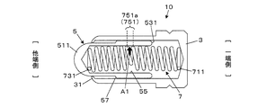
図1および図2は、第1実施形態におけるスプリングコネクタ10の構成例を示す図である。図1および図2は、スプリングコネクタ10を縦断するようにチューブ3および可動ピン5を切り欠いて、チューブ3および可動ピン5については端面を、コイルスプリング7については側面を示した図である。図1は可動ピン5が突出した状態(突出状態)を示しており、図2は可動ピン5の先端部511が押されてチューブ3内に後退した状態(後退状態)を示している。図1および図2に示すように、第1実施形態のスプリングコネクタ10は、有底のチューブ3と、可動ピン5と、コイルスプリング7とを備える。可動ピン5は、先端部511がチューブ3の開口から突出する。コイルスプリング7は、可動ピン5を突出方向に付勢する。
図1および図2は、第1実施形態におけるスプリングコネクタ10の構成例を示す図である。図1および図2は、スプリングコネクタ10を縦断するようにチューブ3および可動ピン5を切り欠いて、チューブ3および可動ピン5については端面を、コイルスプリング7については側面を示した図である。図1は可動ピン5が突出した状態(突出状態)を示しており、図2は可動ピン5の先端部511が押されてチューブ3内に後退した状態(後退状態)を示している。図1および図2に示すように、第1実施形態のスプリングコネクタ10は、有底のチューブ3と、可動ピン5と、コイルスプリング7とを備える。可動ピン5は、先端部511がチューブ3の開口から突出する。コイルスプリング7は、可動ピン5を突出方向に付勢する。
チューブ3は、導電性の材料(例えば、銅又は銅合金等)により作られた有底の筒状体であり、開口する他端側において可動ピン5を摺動可能に保持する。チューブ3の開口端は、かしめ加工によって内側に曲げられて係止部31とされており、可動ピン5の抜けを防止する。
可動ピン5は、導電性の材料(例えば、銅又は銅合金等)により作られる。可動ピン5は、小径部51と、小径部51より外径が大径の大径部53とで構成され、突出方向とは反対側(一端側)に開口する穴部55を有する。小径部51および大径部53の内径は同じである。小径部51の内周面および大径部53の内周面によって、一定内径の穴部55が画成されている。小径部51の先端である先端部511は、接触対象の端子と接触する接触部となる。小径部51と大径部53とは外径の段差部分が有段で繋がっており、両者の間のテーパー状の段差面57がチューブ3の係止部31と当接して、可動ピン5がチューブ3から抜けるのを防ぐ構成となっている。したがって、大径部53は、小径部51がチューブ3から突出した状態であってもチューブ3内に位置する。
コイルスプリング7は、両端部711,731に係る巻回部が座巻部とされた両端がクローズエンドのコイルスプリングである。コイルスプリング7は、例えば、ピアノ線やステンレス線材により作られる。なお、コイルスプリング7は、絶縁材で作られていてもよいし、絶縁被膜で被覆されたものでもよい。このコイルスプリング7は、一端部711がチューブ3の底部に当接し、他端部731が穴部55の底部に当接して、可動ピン5を突出方向に付勢する。
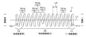
図3は、コイルスプリング7の構成を説明する説明図である。図3は、図1に示す突出状態のスプリングコネクタ10からコイルスプリング7のみを抜き出した側面図である。図3に示すように、コイルスプリング7は、一端部711に係る座巻部71と、他端部731に係る座巻部73と、一端部711と他端部731との間の有効巻数部分75と、で構成されている。座巻部71を、以下適宜「一端座巻部」という。座巻部73を、以下適宜「他端座巻部」という。
有効巻数部分75は、複数の巻回部751(751a,751b)を有する。1ピッチL2に相当する部分が、1つの巻回部751に対応する。有効巻数部分75の巻回部751は、一端座巻部71の巻回中心と、他端座巻部73の巻回中心とを結んだ軸直線L1に対して巻回中心が偏心した偏心巻回部751aを含む。すなわち、有効巻数部分75は、この偏心巻回部751aと、巻回中心が軸直線L1上にあって偏心していない巻回部751bと、を有する。巻回部751bを、以下適宜「非偏心巻回部」という。第1実施形態では、有効巻数部分75の巻回部751のうちの1つが偏心巻回部751aとされている。偏心巻回部751aは、図1および図2では穴部55の内部に位置しているが、穴部55の外側に設けても良い。この場合、コイルスプリング7自体が押されて屈曲した際に穴部55の内部に位置する巻回部751bの一部がピン内部側面を押して側圧を与えることになる。
偏心巻回部751aの外径は、当該偏心巻回部751aに隣り合う巻回部751(非偏心巻回部751b)の外径より小さい外径とされる。第1実施形態では、非偏心巻回部751bは全て同じ外径とされ、それよりも小さい外径として偏心巻回部751aの外径が定められる。なお、本実施形態では偏心巻回部751aをコイルスプリング7の全長または有効巻線部分75の略中央に設けているが、設ける位置はこれに限らない。
一端座巻部71の外径は、一端座巻部71に隣り合う巻回部751(非偏心巻回部751b)の外径より小さい外径とされる。他端座巻部73の外径は、他端座巻部73に隣り合う巻回部751(非偏心巻回部751b)の外径より小さい外径とされる。第1実施形態では、一端座巻部71と他端座巻部73とが同じ外径とされ、当該外径が、非偏心巻回部751bよりも小さい外径として定められる。
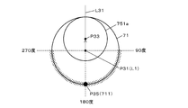
一端部711および他端部731は、それぞれ所定の位置条件を満たす位置となるように構成されている。図4は、一端部711の位置条件を説明する説明図である。図4は、図3の軸直線L1の直線方向から一端部711をみた平面視における、一端座巻部71と偏心巻回部751aとの位置関係を模式的に示している。一端座巻部71および偏心巻回部751aの巻回については円で、一端部711についてはP35として大きい黒色の円で示している。当該平面視において、軸直線L1の位置は、一端座巻部71の中心に対応する位置となり、図4では黒色の円の基点P31で示される。当該平面視において、一端部711の位置は、軸直線L1の位置を示す基点P31から偏心巻回部751aの巻回中心P33に向かう線(基準線)L31に基づいて定められる。具体的には、一端部711の位置は、基準線L31と、基点P31から一端部711に向かう線とのなす角が当該平面視において時計回りで90度以上270度以下となる位置とされる。つまり、一端部711の位置は、偏心巻回部751aの図4中に矢印で示す偏心の向きに対して90度以上離れた、図4中にハッチングを付して示す角度範囲内となるように定められる。例えば、図1および図2に示した例の場合、一端部711および他端部731の位置は、基準線L31に対するなす角が180度となる位置P35となるように定められている。位置P35は、偏心の向きから180度離れた位置とも言える。
他端部731の位置についても同様に定められる。すなわち、軸直線L1の直線方向から他端部731をみた平面視における軸直線L1の位置を示す基点から、偏心巻回部751aの巻回中心に向かう線を基準線とする。そして、他端部731の位置は、当該基準線と、基点から他端部731に向かう線とのなす角が当該平面視において時計回りで90度以上270度以下となる位置として定められる。
一端部711および他端部731の位置に関する作用効果について説明する。可動ピン5の先端部511が押されてコイルスプリング7が収縮すると、弾性によってコイルスプリング7に反発力が生じる。その反発力が生じる起点は、コイルスプリング7の一端部711および他端部731である。図4に示すように、一端部711および他端部731の位置は、偏心巻回部751aの図4中に矢印で示す偏心の向きに対して90度より離れており、当該平面視において時計回りで90度以上270度以下である。このため、一端部711および他端部731の位置を起点に生じた反発力により、偏心巻回部751aを、図2中の矢印A1の方向(偏心方向)に動かすように作用する。
一端部711および他端部731と、偏心巻回部751aとの位置関係を上述のようにすることにより、コイルスプリング7を確実に屈曲させることができる。
スプリングコネクタ10の使用時には図2のような作用効果が奏される。使用時に接触対象の端子が先端部511に押し付けられると、可動ピン5が後退方向へ移動してコイルスプリング7が収縮する。すると、図2に示すように、コイルスプリング7が偏心巻回部751aの部分でその偏心方向に屈曲する。偏心方向とは、図2中に矢印A1で示す方向であり、軸直線L1に対して偏心巻回部751aの巻回中心が偏心している方向であり、図4に示す平面視における基点P31から巻回中心P33に向かう方向である。偏心方向(矢印A1で示す径方向)の力が作用して、可動ピン5の外周面(穴部55の外周部分)がチューブ3の内周面に押し付けられる。よって、使用時において可動ピン5とチューブ3とを確実に接触させることができ、可動ピン5とチューブ3との間の安定した電気的接続が実現できる。コイルスプリング7が収縮したとしても、可動ピン5の後端面531の後方(可動ピン5が押し込まれる方向)がスペースのままとなる。このため、コイルスプリング7の一端側の部分が可動ピン5の後退方向への移動を妨げることがない。したがって、使用時における可動ピン5の移動を阻害することなく、スプリングコネクタ10における接触安定性の向上を図ることができる技術を提供できる。
〔第2実施形態〕
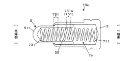
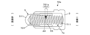
図5および図6は、第2実施形態におけるスプリングコネクタ10aの構成例を示す図である。図5および図6は、スプリングコネクタ10aを縦断するようにチューブ3および可動ピン5を切り欠いて、チューブ3および可動ピン5については端面を、コイルスプリング7aについては側面を示した図である。図5は可動ピン5の突出状態を、図6は可動ピン5の後退状態をそれぞれ示している。図5および図6に示すように、第2実施形態のスプリングコネクタ10aは、第1実施形態と同様に、有底のチューブ3と、可動ピン5と、コイルスプリング7aと、を備える。可動ピン5は、先端部511がチューブ3の開口から突出し、突出方向とは反対側に開口する穴部55を有する。コイルスプリング7aは、一端部がチューブ3の底部に当接し、他端部が穴部55の底部に当接して、可動ピン5を突出方向に付勢する。
図5および図6は、第2実施形態におけるスプリングコネクタ10aの構成例を示す図である。図5および図6は、スプリングコネクタ10aを縦断するようにチューブ3および可動ピン5を切り欠いて、チューブ3および可動ピン5については端面を、コイルスプリング7aについては側面を示した図である。図5は可動ピン5の突出状態を、図6は可動ピン5の後退状態をそれぞれ示している。図5および図6に示すように、第2実施形態のスプリングコネクタ10aは、第1実施形態と同様に、有底のチューブ3と、可動ピン5と、コイルスプリング7aと、を備える。可動ピン5は、先端部511がチューブ3の開口から突出し、突出方向とは反対側に開口する穴部55を有する。コイルスプリング7aは、一端部がチューブ3の底部に当接し、他端部が穴部55の底部に当接して、可動ピン5を突出方向に付勢する。
第2実施形態では、コイルスプリング7aにおいて、有効巻数部分の各巻回部751の巻回中心が、偏心巻回部751aに近づくに従って徐々に変位した構成となっている。具体的には、図5又は図6の例では、穴部55の内部に位置する巻回部751であって、中央付近の巻回部751が、偏心巻回部751aに該当する。当該偏心巻回部751a以外の各巻回部751は、巻回中心が偏心巻回部751aの偏心方向へと両端側から段階的に変位して構成されている。これにより、コイルスプリング7aは、全体的に、長手方向が偏心方向に屈曲した形状を有する。
本構成のスプリングコネクタ10aでは、使用時に先端部511を押して可動ピン5をチューブ3に押し込むと、偏心巻回部751aの偏心方向である図6中に矢印A4で示す径方向に力が作用する。すると、偏心巻回部751aの偏心位置がさらに偏心方向にずれるように移動してコイルスプリング7aが屈曲し、偏心巻回部751aに係る巻回部分が穴部55の内周面を押して、可動ピン5の外周面をチューブ3の内周面に押し付ける。よって、第1実施形態と同様の効果を奏することができる。
以上、2つの実施形態を説明したが、本発明を適用可能な形態は上記した実施形態に限定されるものではなく、適宜構成要素の追加・省略・変更を施すことができる。
例えば、コイルスプリングの有効巻数部分75における偏心巻回部751aの配置は、上記各実施形態に例示した配置に限定されない。図7~図12は、変形例のスプリングコネクタが備えるコイルスプリング7b,7c,7d,7e,7f,7gの構成をそれぞれ示す図である。
例えば、図7に示すように、有効巻数部分75が偏心巻回部751aを複数有する構成としてもよい。図7の例では、3つの偏心巻回部751aを有している。これによれば、有効巻数部分75において偏心巻回部751aを複数有するコイルスプリング7bを実現できる。
図8に示すように、非偏心巻回部751bと偏心巻回部751aとを交互に配置して有効巻数部分75を構成してもよい。図8では、非偏心巻回部751bと偏心巻回部751aとが2つずつ交互に配置された有効巻数部分75の構成例を示している。非偏心巻回部751bと偏心巻回部751aとを1つずつ交互に配置した構成としてもよい。これによれば、有効巻数部分75において非偏心巻回部751bと偏心巻回部751aとが交互に配置されたコイルスプリング7cを実現できる。
図9に示すように、有効巻数部分75における偏心巻回部751aを不規則に配置してもよい。これによれば、有効巻数部分75において偏心巻回部751aが不規則に配置されたコイルスプリング7dを実現できる。
図10に示すように、有効巻数部分75が、非偏心巻回部751bおよび偏心巻回部751aの他に、異種偏心巻回部751cを有する構成としてもよい。異種偏心巻回部751cは、コイルスプリングの一端部711又は他端部731を軸直線L1の直線方向からみた平面視(図4を参照)において、軸直線L1の位置を示す基点から偏心巻回部751aの巻回中心に向かう方向とは異なる方向に巻回中心を有する巻回部である。より詳細には、当該平面視において、線(基準線)L31と、基点P31から異種偏心巻回部751cの巻回中心に向かう線と、のなす角が90度以下となる位置に巻回中心を有する巻回部が異種偏心巻回部751cである。線(基準線)L31は、軸直線L1の位置を示す基点P31から偏心巻回部751aの巻回中心P33に向かう線である。図10の例では、有効巻数部分75は、基点から偏心巻回部751aの巻回中心に向かう方向とは逆向きの方向に巻回中心を有する異種偏心巻回部751cを1つ含んでいる。これによれば、有効巻数部分75において、軸直線L1に対して、偏心巻回部751aが位置する方向とは異なる方向に偏心した異種偏心巻回部751cを有するコイルスプリング7eを実現できる。
図11に示すように、コイルスプリング7fのピッチは、不等ピッチであってもよい。具体的には、例えば、非偏心巻回部751bのピッチL33と比べて偏心巻回部751aのピッチL32を狭くしてもよい。これとは逆に、非偏心巻回部751bのピッチL33と比べて偏心巻回部751aのピッチL32を広くしてもよい。これによれば、ピッチが不等間隔のコイルスプリング7fを用いてスプリングコネクタを構成できる。
また、コイルスプリングの有効巻数部分において、異なる外径の巻回部を含む構成としてもよい。例えば、図12に示すように、第2実施形態として示した有効巻数部分75の各巻回部751の巻回中心が偏心巻回部751aに近づくに従って徐々に変位したコイルスプリングの構成において、各巻回部751の外径についても偏心巻回部751aに近づくに従って徐々に小さくするとしてもよい。これによれば、有効巻数部分75において異なる外径の巻回部751を有するコイルスプリング7gを実現できる。
また、上記各実施形態や各変形例では、両端部に係る巻回部が座巻部とされた両端がクローズエンドのコイルスプリングを例示したが、両端がオープンエンドのコイルスプリングを用いた構成であってもよい。クローズエンドとは、端部を、ばね線の間隔がない状態にする巻き方のことである。オープンエンドとは、端部を、ばね線の間隔がある状態にする巻き方のことである。
また、スプリングコネクタを構成するコイルスプリングの断面形状(線材の断面形状)は特に限定されるものではなく、例えば、円形状や楕円形状、多角形状等であってもよい。また、1つの巻回部の巻回形状(図4の平面視における形状)についても円形状に限らず、例えば、矩形状や楕円形状等の他の形状としてもよい。
幾つかの実施形態およびその変形例について説明した。これらの開示は、次のように概括することができる。
本開示の態様は、チューブと、先端部が前記チューブの開口から突出し、突出方向とは反対側に開口する穴部を有する可動ピンと、前記可動ピンを前記突出方向に付勢するコイルスプリングと、を備え、前記コイルスプリングは、一端部に係る巻回部の巻回中心と他端部に係る巻回部の巻回中心とを結んだ軸直線に対して、巻回中心が偏心した偏心巻回部を有する、スプリングコネクタである。
本開示の態様によれば、コイルスプリングが、両端部に係る巻回部の巻回中心同士を結んだ軸直線に対して巻回中心が偏心した偏心巻回部を有して構成される。本構成によれば、先端部が押されて可動ピンがチューブに押し込まれたときに、少なくとも偏心巻回部によって可動ピンがチューブに押し付けられる作用力が働く。よって、使用時において可動ピンとチューブとを確実に接触させることができ、可動ピンとチューブとの間の安定した電気的接続が実現できる。一方で、コイルスプリングの一端側の巻回部が可動ピンの移動を妨げることが抑制される。したがって、使用時における可動ピンの移動範囲を広げることができ、その分だけ、スプリングコネクタの全長を短くすることができる。また、可動ピンとチューブとの間の接触安定性の向上を図ることができる。
前記一端部は、前記軸直線の直線方向からの平面視において、当該軸直線の位置を示す基点から前記偏心巻回部の巻回中心に向かう線と、前記基点から当該一端部に向かう線とのなす角が時計回りで90度以上270度以下の位置にあり、
前記他端部は、前記平面視において、前記基点から前記偏心巻回部の巻回中心に向かう線と、前記基点から当該他端部に向かう線とのなす角が時計回りで90度以上270度以下の位置にある、
としてもよい。
前記他端部は、前記平面視において、前記基点から前記偏心巻回部の巻回中心に向かう線と、前記基点から当該他端部に向かう線とのなす角が時計回りで90度以上270度以下の位置にある、
としてもよい。
前記コイルスプリングは、両端がクローズエンドである、としてもよい。
前記コイルスプリングは、前記一端部に係る座巻部の外径が当該座巻部に隣り合う巻回部の外径より小さく、前記他端部に係る座巻部の外径が当該座巻部に隣り合う巻回部の外径より小さい、としてもよい。
前記偏心巻回部は、前記穴部の内部に位置する、としてもよい。
前記偏心巻回部の外径は、前記偏心巻回部に隣り合う巻回部の外径より小さい、としてもよい。
前記偏心巻回部は、前記一端部と前記他端部との間の有効巻線部分にあり、
前記偏心巻回部の外径は、前記有効巻数部分のうちの前記偏心巻回部以外の巻回部の外径より小さい、としてもよい。
前記偏心巻回部の外径は、前記有効巻数部分のうちの前記偏心巻回部以外の巻回部の外径より小さい、としてもよい。
前記コイルスプリングは、前記偏心巻回部を複数有する、としてもよい。
前記コイルスプリングは、前記平面視において、前記基点から前記偏心巻回部の巻回中心に向かう方向とは異なる方向に巻回中心を有する異種偏心巻回部を、前記有効巻数部分に有する、としてもよい。
前記偏心巻回部は、前記一端部と前記他端部との間の有効巻線部分にあり、
前記有効巻数部分の各巻回部の巻回中心は、前記偏心巻回部に近づくに従って徐々に変位している、としてもよい。
前記有効巻数部分の各巻回部の巻回中心は、前記偏心巻回部に近づくに従って徐々に変位している、としてもよい。
前記コイルスプリングは、不等ピッチである、としてもよい。
10,10a…スプリングコネクタ
3…チューブ
5…可動ピン
511…先端部
55…穴部
7,7a,7b,7c,7d,7e,7f,7g…コイルスプリング
71…一端座巻部
711…一端部
73…他端座巻部
731…他端部
75…有効巻数部分
751…巻回部
751a…偏心巻回部
751b…非偏心巻回部
751c…異種偏心巻回部
3…チューブ
5…可動ピン
511…先端部
55…穴部
7,7a,7b,7c,7d,7e,7f,7g…コイルスプリング
71…一端座巻部
711…一端部
73…他端座巻部
731…他端部
75…有効巻数部分
751…巻回部
751a…偏心巻回部
751b…非偏心巻回部
751c…異種偏心巻回部
Claims (10)
- チューブと、
先端部が前記チューブの開口から突出し、突出方向とは反対側に開口する穴部を有する可動ピンと、
前記可動ピンを前記突出方向に付勢するコイルスプリングと、
を備え、
前記コイルスプリングは、一端部に係る巻回部の巻回中心と他端部に係る巻回部の巻回中心とを結んだ軸直線に対して、巻回中心が偏心した偏心巻回部を有する、
スプリングコネクタ。 - 前記一端部は、前記軸直線の直線方向からの平面視において、当該軸直線の位置を示す基点から前記偏心巻回部の巻回中心に向かう線と、前記基点から当該一端部に向かう線とのなす角が時計回りで90度以上270度以下の位置にあり、
前記他端部は、前記平面視において、前記基点から前記偏心巻回部の巻回中心に向かう線と、前記基点から当該他端部に向かう線とのなす角が時計回りで90度以上270度以下の位置にある、
請求項1に記載のスプリングコネクタ。 - 前記コイルスプリングは、両端がクローズエンドである、
請求項1又は2に記載のスプリングコネクタ。 - 前記コイルスプリングは、前記一端部に係る座巻部の外径が当該座巻部に隣り合う巻回部の外径より小さく、前記他端部に係る座巻部の外径が当該座巻部に隣り合う巻回部の外径より小さい、
請求項3に記載のスプリングコネクタ。 - 前記偏心巻回部は、前記穴部の内部に位置する、
請求項1~4の何れか一項に記載のスプリングコネクタ。 - 前記偏心巻回部の外径は、前記偏心巻回部に隣り合う巻回部の外径より小さい、
請求項1~5の何れか一項に記載のスプリングコネクタ。 - 前記偏心巻回部は、前記一端部と前記他端部との間の有効巻線部分にあり、
前記偏心巻回部の外径は、前記有効巻数部分のうちの前記偏心巻回部以外の巻回部の外径より小さい、
請求項1~6の何れか一項に記載のスプリングコネクタ。 - 前記コイルスプリングは、前記平面視において、前記基点から前記偏心巻回部の巻回中心に向かう方向とは異なる方向に巻回中心を有する異種偏心巻回部を、前記有効巻数部分に有する、
請求項1~7の何れか一項に記載のスプリングコネクタ。 - 前記偏心巻回部は、前記一端部と前記他端部との間の有効巻線部分にあり、
前記有効巻数部分の各巻回部の巻回中心は、前記偏心巻回部に近づくに従って徐々に変位している、
請求項1~6の何れか一項に記載のスプリングコネクタ。 - 前記コイルスプリングは、不等ピッチである、
請求項1~9の何れか一項に記載のスプリングコネクタ。
Priority Applications (3)
| Application Number | Priority Date | Filing Date | Title |
|---|---|---|---|
| US17/922,185 US12261402B2 (en) | 2020-05-07 | 2021-04-30 | Spring connector |
| EP21800774.8A EP4148913A4 (en) | 2020-05-07 | 2021-04-30 | SPRING CONNECTOR |
| CN202180032138.8A CN115552730A (zh) | 2020-05-07 | 2021-04-30 | 弹簧连接器 |
Applications Claiming Priority (2)
| Application Number | Priority Date | Filing Date | Title |
|---|---|---|---|
| JP2020081785A JP7526028B2 (ja) | 2020-05-07 | 2020-05-07 | スプリングコネクタ |
| JP2020-081785 | 2020-05-07 |
Publications (1)
| Publication Number | Publication Date |
|---|---|
| WO2021225121A1 true WO2021225121A1 (ja) | 2021-11-11 |
Family
ID=78409550
Family Applications (1)
| Application Number | Title | Priority Date | Filing Date |
|---|---|---|---|
| PCT/JP2021/017237 Ceased WO2021225121A1 (ja) | 2020-05-07 | 2021-04-30 | スプリングコネクタ |
Country Status (6)
| Country | Link |
|---|---|
| US (1) | US12261402B2 (ja) |
| EP (1) | EP4148913A4 (ja) |
| JP (1) | JP7526028B2 (ja) |
| CN (1) | CN115552730A (ja) |
| TW (1) | TW202143558A (ja) |
| WO (1) | WO2021225121A1 (ja) |
Cited By (1)
| Publication number | Priority date | Publication date | Assignee | Title |
|---|---|---|---|---|
| WO2023228846A1 (ja) * | 2022-05-26 | 2023-11-30 | 株式会社ヨコオ | プローブ |
Citations (4)
| Publication number | Priority date | Publication date | Assignee | Title |
|---|---|---|---|---|
| JPH11162545A (ja) * | 1993-02-10 | 1999-06-18 | Yokowo Co Ltd | 電気接続用コネクタ |
| US20050280433A1 (en) * | 2004-06-16 | 2005-12-22 | Nelson Larre H | Electrical test probes, methods of making, and methods of using |
| CN200953400Y (zh) * | 2006-09-06 | 2007-09-26 | 乔盟弹簧股份有限公司 | 探针式连接器改良结构 |
| WO2011058646A1 (ja) * | 2009-11-13 | 2011-05-19 | テスト ツーリング ソリューションズ グループ ピイ ティ イー リミテッド | プローブピン |
Family Cites Families (8)
| Publication number | Priority date | Publication date | Assignee | Title |
|---|---|---|---|---|
| DE3012491C2 (de) | 1980-03-31 | 1984-10-25 | Feinmetall Gmbh, 7033 Herrenberg | Kontaktbaustein zum Prüfen von elektrischen Leiterplatten |
| JP2529084Y2 (ja) | 1991-02-22 | 1997-03-12 | 株式会社ヨコオ | スプリングコネクタ |
| JP2001255340A (ja) * | 2000-03-13 | 2001-09-21 | Yokowo Co Ltd | コンタクトプローブ及び該コンタクトプローブを設けたicパッケージ検査用ソケット |
| JP2002008761A (ja) * | 2000-06-23 | 2002-01-11 | Tyco Electronics Amp Kk | スプリングコンタクト |
| CN201515073U (zh) * | 2009-09-30 | 2010-06-23 | 中兴通讯股份有限公司 | 一种探针 |
| CN103026242A (zh) * | 2010-07-29 | 2013-04-03 | 西川秀雄 | 检验夹具及触头 |
| JP5568441B2 (ja) * | 2010-10-27 | 2014-08-06 | 日置電機株式会社 | 電源接続端子 |
| KR101552553B1 (ko) | 2014-09-23 | 2015-10-01 | 리노공업주식회사 | 검사장치용 컨택트 프로브 |
-
2020
- 2020-05-07 JP JP2020081785A patent/JP7526028B2/ja active Active
-
2021
- 2021-04-30 US US17/922,185 patent/US12261402B2/en active Active
- 2021-04-30 EP EP21800774.8A patent/EP4148913A4/en active Pending
- 2021-04-30 WO PCT/JP2021/017237 patent/WO2021225121A1/ja not_active Ceased
- 2021-04-30 CN CN202180032138.8A patent/CN115552730A/zh active Pending
- 2021-05-04 TW TW110116030A patent/TW202143558A/zh unknown
Patent Citations (4)
| Publication number | Priority date | Publication date | Assignee | Title |
|---|---|---|---|---|
| JPH11162545A (ja) * | 1993-02-10 | 1999-06-18 | Yokowo Co Ltd | 電気接続用コネクタ |
| US20050280433A1 (en) * | 2004-06-16 | 2005-12-22 | Nelson Larre H | Electrical test probes, methods of making, and methods of using |
| CN200953400Y (zh) * | 2006-09-06 | 2007-09-26 | 乔盟弹簧股份有限公司 | 探针式连接器改良结构 |
| WO2011058646A1 (ja) * | 2009-11-13 | 2011-05-19 | テスト ツーリング ソリューションズ グループ ピイ ティ イー リミテッド | プローブピン |
Non-Patent Citations (1)
| Title |
|---|
| See also references of EP4148913A4 * |
Cited By (2)
| Publication number | Priority date | Publication date | Assignee | Title |
|---|---|---|---|---|
| WO2023228846A1 (ja) * | 2022-05-26 | 2023-11-30 | 株式会社ヨコオ | プローブ |
| JP2023173519A (ja) * | 2022-05-26 | 2023-12-07 | 株式会社ヨコオ | プローブ |
Also Published As
| Publication number | Publication date |
|---|---|
| CN115552730A (zh) | 2022-12-30 |
| JP2021177446A (ja) | 2021-11-11 |
| JP7526028B2 (ja) | 2024-07-31 |
| US20230178906A1 (en) | 2023-06-08 |
| EP4148913A1 (en) | 2023-03-15 |
| EP4148913A4 (en) | 2024-05-08 |
| US12261402B2 (en) | 2025-03-25 |
| TW202143558A (zh) | 2021-11-16 |
Similar Documents
| Publication | Publication Date | Title |
|---|---|---|
| KR101894965B1 (ko) | 프로브 핀 및 ic 소켓 | |
| US7331821B2 (en) | Electrical connector | |
| JP4770752B2 (ja) | 接触子装置 | |
| WO2014196620A1 (ja) | 雌端子 | |
| CN104285340A (zh) | 具有端子的同轴电缆及其制造方法 | |
| WO2021225121A1 (ja) | スプリングコネクタ | |
| JP2006098254A (ja) | プローブ | |
| CN108702861A (zh) | 屏蔽端子连接结构 | |
| JP6772752B2 (ja) | 内燃機関用の点火コイル | |
| WO2014203758A1 (ja) | コネクタ | |
| EP0748516B1 (en) | Electric lamp | |
| JP2016131290A (ja) | ノイズフィルタ及びノイズフィルタ用ホルダ | |
| JP2025522488A (ja) | ケーブルグランド | |
| JP2006278336A (ja) | 電気コネクタージャック | |
| US20220416462A1 (en) | Spring connector | |
| WO2021085229A1 (ja) | スプリングコネクタおよびスプリングコネクタの製造方法 | |
| CN118946811A (zh) | 弹簧连接器 | |
| JPH03214574A (ja) | コネクタの接続機構 | |
| JP2021177446A5 (ja) | ||
| JP2010096735A (ja) | コンタクトプローブ端子 | |
| JP2023174009A5 (ja) | ||
| JP7560162B2 (ja) | オーディオプラグ | |
| JP7515155B2 (ja) | 圧着接続構造及び圧着接続方法 | |
| US5299953A (en) | Cutting and clamping sleeve contact | |
| JP7305265B2 (ja) | 端子付き電線 |
Legal Events
| Date | Code | Title | Description |
|---|---|---|---|
| 121 | Ep: the epo has been informed by wipo that ep was designated in this application |
Ref document number: 21800774 Country of ref document: EP Kind code of ref document: A1 |
|
| NENP | Non-entry into the national phase |
Ref country code: DE |
|
| ENP | Entry into the national phase |
Ref document number: 2021800774 Country of ref document: EP Effective date: 20221207 |
|
| WWG | Wipo information: grant in national office |
Ref document number: 17922185 Country of ref document: US |