WO2021230174A1 - プラズマ生成装置 - Google Patents
プラズマ生成装置 Download PDFInfo
- Publication number
- WO2021230174A1 WO2021230174A1 PCT/JP2021/017603 JP2021017603W WO2021230174A1 WO 2021230174 A1 WO2021230174 A1 WO 2021230174A1 JP 2021017603 W JP2021017603 W JP 2021017603W WO 2021230174 A1 WO2021230174 A1 WO 2021230174A1
- Authority
- WO
- WIPO (PCT)
- Prior art keywords
- power supply
- electrode
- flow path
- plasma
- gas
- Prior art date
- Legal status (The legal status is an assumption and is not a legal conclusion. Google has not performed a legal analysis and makes no representation as to the accuracy of the status listed.)
- Ceased
Links
Images


Classifications
-
- F—MECHANICAL ENGINEERING; LIGHTING; HEATING; WEAPONS; BLASTING
- F01—MACHINES OR ENGINES IN GENERAL; ENGINE PLANTS IN GENERAL; STEAM ENGINES
- F01N—GAS-FLOW SILENCERS OR EXHAUST APPARATUS FOR MACHINES OR ENGINES IN GENERAL; GAS-FLOW SILENCERS OR EXHAUST APPARATUS FOR INTERNAL-COMBUSTION ENGINES
- F01N3/00—Exhaust or silencing apparatus having means for purifying, rendering innocuous, or otherwise treating exhaust
- F01N3/02—Exhaust or silencing apparatus having means for purifying, rendering innocuous, or otherwise treating exhaust for cooling, or for removing solid constituents of, exhaust
- F01N3/021—Exhaust or silencing apparatus having means for purifying, rendering innocuous, or otherwise treating exhaust for cooling, or for removing solid constituents of, exhaust by means of filters
- F01N3/023—Exhaust or silencing apparatus having means for purifying, rendering innocuous, or otherwise treating exhaust for cooling, or for removing solid constituents of, exhaust by means of filters using means for regenerating the filters, e.g. by burning trapped particles
- F01N3/027—Exhaust or silencing apparatus having means for purifying, rendering innocuous, or otherwise treating exhaust for cooling, or for removing solid constituents of, exhaust by means of filters using means for regenerating the filters, e.g. by burning trapped particles using electric or magnetic heating means
- F01N3/0275—Exhaust or silencing apparatus having means for purifying, rendering innocuous, or otherwise treating exhaust for cooling, or for removing solid constituents of, exhaust by means of filters using means for regenerating the filters, e.g. by burning trapped particles using electric or magnetic heating means using electric discharge means
-
- H—ELECTRICITY
- H05—ELECTRIC TECHNIQUES NOT OTHERWISE PROVIDED FOR
- H05H—PLASMA TECHNIQUE; PRODUCTION OF ACCELERATED ELECTRICALLY-CHARGED PARTICLES OR OF NEUTRONS; PRODUCTION OR ACCELERATION OF NEUTRAL MOLECULAR OR ATOMIC BEAMS
- H05H1/00—Generating plasma; Handling plasma
- H05H1/24—Generating plasma
- H05H1/2406—Generating plasma using dielectric barrier discharges, i.e. with a dielectric interposed between the electrodes
- H05H1/2439—Surface discharges, e.g. air flow control
-
- H—ELECTRICITY
- H05—ELECTRIC TECHNIQUES NOT OTHERWISE PROVIDED FOR
- H05H—PLASMA TECHNIQUE; PRODUCTION OF ACCELERATED ELECTRICALLY-CHARGED PARTICLES OR OF NEUTRONS; PRODUCTION OR ACCELERATION OF NEUTRAL MOLECULAR OR ATOMIC BEAMS
- H05H1/00—Generating plasma; Handling plasma
- H05H1/24—Generating plasma
- H05H1/2406—Generating plasma using dielectric barrier discharges, i.e. with a dielectric interposed between the electrodes
- H05H1/2418—Generating plasma using dielectric barrier discharges, i.e. with a dielectric interposed between the electrodes the electrodes being embedded in the dielectric
-
- H—ELECTRICITY
- H05—ELECTRIC TECHNIQUES NOT OTHERWISE PROVIDED FOR
- H05H—PLASMA TECHNIQUE; PRODUCTION OF ACCELERATED ELECTRICALLY-CHARGED PARTICLES OR OF NEUTRONS; PRODUCTION OR ACCELERATION OF NEUTRAL MOLECULAR OR ATOMIC BEAMS
- H05H1/00—Generating plasma; Handling plasma
- H05H1/24—Generating plasma
- H05H1/2406—Generating plasma using dielectric barrier discharges, i.e. with a dielectric interposed between the electrodes
- H05H1/2425—Generating plasma using dielectric barrier discharges, i.e. with a dielectric interposed between the electrodes the electrodes being flush with the dielectric
-
- H—ELECTRICITY
- H05—ELECTRIC TECHNIQUES NOT OTHERWISE PROVIDED FOR
- H05H—PLASMA TECHNIQUE; PRODUCTION OF ACCELERATED ELECTRICALLY-CHARGED PARTICLES OR OF NEUTRONS; PRODUCTION OR ACCELERATION OF NEUTRAL MOLECULAR OR ATOMIC BEAMS
- H05H1/00—Generating plasma; Handling plasma
- H05H1/24—Generating plasma
- H05H1/2406—Generating plasma using dielectric barrier discharges, i.e. with a dielectric interposed between the electrodes
- H05H1/2437—Multilayer systems
-
- F—MECHANICAL ENGINEERING; LIGHTING; HEATING; WEAPONS; BLASTING
- F01—MACHINES OR ENGINES IN GENERAL; ENGINE PLANTS IN GENERAL; STEAM ENGINES
- F01N—GAS-FLOW SILENCERS OR EXHAUST APPARATUS FOR MACHINES OR ENGINES IN GENERAL; GAS-FLOW SILENCERS OR EXHAUST APPARATUS FOR INTERNAL-COMBUSTION ENGINES
- F01N2240/00—Combination or association of two or more different exhaust treating devices, or of at least one such device with an auxiliary device, not covered by indexing codes F01N2230/00 or F01N2250/00, one of the devices being
- F01N2240/28—Combination or association of two or more different exhaust treating devices, or of at least one such device with an auxiliary device, not covered by indexing codes F01N2230/00 or F01N2250/00, one of the devices being a plasma reactor
-
- F—MECHANICAL ENGINEERING; LIGHTING; HEATING; WEAPONS; BLASTING
- F01—MACHINES OR ENGINES IN GENERAL; ENGINE PLANTS IN GENERAL; STEAM ENGINES
- F01N—GAS-FLOW SILENCERS OR EXHAUST APPARATUS FOR MACHINES OR ENGINES IN GENERAL; GAS-FLOW SILENCERS OR EXHAUST APPARATUS FOR INTERNAL-COMBUSTION ENGINES
- F01N2390/00—Arrangements for controlling or regulating exhaust apparatus
- F01N2390/02—Arrangements for controlling or regulating exhaust apparatus using electric components only
-
- H—ELECTRICITY
- H05—ELECTRIC TECHNIQUES NOT OTHERWISE PROVIDED FOR
- H05H—PLASMA TECHNIQUE; PRODUCTION OF ACCELERATED ELECTRICALLY-CHARGED PARTICLES OR OF NEUTRONS; PRODUCTION OR ACCELERATION OF NEUTRAL MOLECULAR OR ATOMIC BEAMS
- H05H2245/00—Applications of plasma devices
- H05H2245/10—Treatment of gases
- H05H2245/17—Exhaust gases
Definitions
- the present invention relates to a plasma generator, and more particularly to a dielectric barrier discharge type plasma generator capable of generating plasma in substantially atmospheric pressure.
- plasma is introduced in the flow path of the exhaust gas.
- An exhaust gas treatment device including a generation device is provided (see, for example, Patent Document 1). Plasma is generated in the flow path of such exhaust gas, and PM is brought into contact with plasma to decompose PM into carbon dioxide and the like.
- plasma generators generate plasma in a plasma generation chamber (vacuum container) that is close to vacuum, but since the flow path of exhaust gas has a pressure that is sufficiently higher than vacuum and is close to atmospheric pressure, it is used in exhaust gas treatment equipment.
- a plasma generation device to be used a device capable of generating plasma in substantially atmospheric pressure is used.
- One such device is a dielectric barrier discharge type plasma generator that uses a dielectric barrier discharge to generate plasma.
- the dielectric barrier discharge type plasma generator is one in which at least one of the pair of electrodes is coated with an insulating material on the side facing the other electrode.
- an AC voltage with a frequency in the range of several tens of Hz to 100 kHz and an AC voltage in the range of 500 V to 10 kV is applied between adjacent electrodes while the pressure between these electrodes is approximately atmospheric pressure, they are adjacent within one cycle of AC.
- the absolute value of the potential difference between the electrodes exceeds the threshold value, a discharge occurs between the adjacent electrodes. Due to this discharge, electric charges adhere to the insulating material, the potential difference between the insulating materials of both electrodes becomes small, and the discharge is stopped.
- One of the pair of electrodes of such a dielectric barrier discharge type plasma generator is arranged in the gas flow path of the exhaust gas treatment device, and the other is a wall made of a conductor constituting the gas flow path.
- an electric discharge is generated in the gas flow path, which is a space between adjacent electrodes, and the gas flowing in the gas flow path is ionized to generate plasma. Then, when PM comes into contact with this plasma, PM is decomposed.
- each electrode is connected to an AC power supply through an AC wiring or to a ground through a ground wiring.
- a cable in which a flexible metal wire is coated with a flexible coating material is usually used for easy handling. The coating material of such a cable deteriorates over a long period of time. Then, when the electrode in the gas flow path or the electrode which is the wall of the gas flow path receives vibration from the gas flow in the gas flow path, the vibration is transmitted to the cable through the electrode to which it is connected.
- an exhaust gas treatment device that decomposes PM in exhaust gas discharged from a diesel engine or the like has been described as an example, but other than that, the gas is generated by ionizing the gas flowing in the gas flow path to generate plasma.
- a similar problem arises in the dielectric barrier discharge type plasma generation device provided in the gas treatment device that performs the treatment for the gas.
- An object to be solved by the present invention is to provide a dielectric barrier discharge type plasma generator provided in a gas processing apparatus and capable of preventing electric leakage and undesired discharge.
- the present invention made to solve the above problems is a plasma generation device provided in a gas processing device for ionizing a gas flowing in a gas flow path to generate plasma.
- An inflexible connecting material that electrically connects the AC power supply and the power supply electrode, d) It is characterized by comprising an insulating material covering the side of one of the power supply electrode and the ground electrode facing the other electrode.
- an inflexible connecting material is used to electrically connect the AC power supply and the power supply electrode.
- the term "inflexible” as used herein means that it does not easily deform, and more specifically, it vibrates within the elastic range even when vibration is applied, and the initial installation state is maintained. That is, if it is initially installed so as not to come into contact with other members or the like, the state of not coming into contact with other members is maintained even if it is subjected to vibration or the like for a long period of time. Therefore, even if vibration is transmitted from the gas flowing in the gas flow path to the connecting material via the power supply electrode (the electrode arranged in the gas flow path or the electrode which is a wall made of a conductor constituting the gas flow path). Since the connecting material does not unexpectedly come into contact with or approach a member other than the power supply electrode in the plasma generator, it is possible to prevent electric leakage and undesired discharge.
- the connecting material may be covered with a covering material in consideration of safety at the time of inspection or the like.
- a protective cover may be installed to cover the connecting material at a distance from the connecting material.
- the insulating material may be provided only on either the power supply electrode or the ground electrode, or may be provided on both of them.
- a non-flexible connecting material similar to the connecting material may be used.
- the AC power supply has a frequency in the range of several tens of Hz (including 50 Hz and 60 Hz, which are commercial frequencies in Japan) to 100 kHz, and is 500 V to 10 kV. Those that generate an AC voltage within the range of can be used.
- a power measuring unit that measures AC power output from the AC power supply and a voltage that controls the AC voltage of the AC power according to the AC power measured by the power measuring unit. It can be provided with a control unit. Thereby, when the AC power fluctuates due to a change in the density or component of the gas between the power supply electrode and the ground electrode, the AC power can be controlled to be within a predetermined range.
- the pulse current due to discharge is detected from the current waveform acquisition unit that acquires the waveform of the AC current output from the AC power supply and the AC current waveform acquired by the current waveform acquisition unit.
- a second voltage control unit that controls the AC voltage of the AC power according to the pulse repetition frequency of the pulse current detected by the pulse current detection unit can be provided.
- the plasma generator according to the present invention may have a plurality of combinations of the power supply electrode and the ground electrode, and a common connecting material may be connected to each of the power supply electrodes. According to this configuration, plasma can be generated simultaneously between a plurality of sets of power supply electrodes and ground electrodes, so that the gas processing capacity can be increased.
- one of the power supply electrode and the ground electrode is a linear tubular electrode, and further, two of the plurality of tubular electrodes are connected. It can be configured to have a connecting flow path to be connected. As a result, the gas flow path can be lengthened while suppressing the size of the tubular electrode in the longitudinal direction, so that the gas can be treated more reliably.
- a plurality of the power supply electrodes and the ground electrode are alternately arranged one by one, and a common connecting material is connected to each of the power supply electrodes. be able to.
- plasma is generated between the power supply electrode and the ground electrode adjacent to each other, and plasma can be generated simultaneously between a plurality of sets of adjacent electrodes, so that the gas processing capacity can be increased.
- plasma is generated between the adjacent (that is, two) ground electrodes.
- the power supply electrode and the ground electrode are flat plate electrodes, and further, either the power supply electrode or the ground electrode is used.
- the gas flow path formed between the and the other can be configured to have a connection flow path connecting the adjacent gas flow paths. As a result, the gas flow path can be lengthened while suppressing the size in the direction parallel to the plate of the flat plate electrode, so that the gas can be processed more reliably.
- the schematic which shows the 1st Embodiment of the plasma generation apparatus which concerns on this invention The schematic diagram which shows the modification of the plasma generation apparatus of 1st Embodiment.
- the schematic diagram which shows the other modification of the plasma generation apparatus of 1st Embodiment AA sectional view showing the second embodiment of the plasma generation apparatus which concerns on this invention.
- BB sectional view of the plasma generation apparatus of the 2nd Embodiment AA sectional view which shows the modification of the plasma generation apparatus of 2nd Embodiment.
- AA sectional view showing a 3rd Embodiment of the plasma generation apparatus which concerns on this invention BB sectional view of the plasma generation apparatus of the third embodiment.
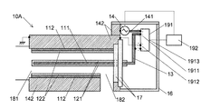
- FIG. 1 shows a schematic configuration of the plasma generation device 10 of the first embodiment.
- the plasma generation device 10 of the first embodiment is provided in the gas treatment device, and has a pipe that serves as a flow path for the gas to be treated (the gas to be treated).
- the tube wall of this tube is made of a conductor and is grounded. This tube wall corresponds to the ground electrode 112 of the plasma generator 10.
- the power supply electrode 111 is arranged in the pipe of the ground electrode 112, that is, in the gas flow path.
- the tube of the ground electrode 112 is a cylinder
- the power supply electrode 111 is a cylindrical conductor arranged at the center of the cylinder.
- One end of the power supply electrode 111 extends to one end (left side of the same) of the tube of the ground electrode 112, and the other end (right side of the same) is the other end of the tube of the ground electrode 112 (right side of the same). ) Extends to the outside.
- an insulating material 121 on the power supply side made of an insulator (dielectric) is provided so as to cover the entire surface. Further, on the inner surface of the tube of the grounding electrode 112, an insulating material 122 on the grounding side made of an insulator (dielectric) is provided so as to cover the entire surface thereof.
- the power supply side insulating material 121 and the ground side insulating material 122 are provided, but only one of them may be provided.
- the portion extending to the outside of the tube of the ground electrode 112 is one of the connecting materials 13 which is a conductor and is a rod made of an inflexible material (lower part of FIG. 1). The end of the side) is connected. Further, the plasma generation device 10 has an AC power supply 14, and the other end (upper side) of the connecting material 13 is connected to one electrode 141 of the AC power supply 14.
- the connecting material 13 is not covered with a covering material, and is not in contact with members other than the power electrode 111 and the electrode 141 of the AC power supply 14.
- the other electrode 142 of the AC power supply 14 is formed so as to cover the periphery of the tube of the ground electrode 112, and is grounded together with the ground electrode 112.
- a power supply having a frequency in the range of several tens of Hz to 100 kHz and an output voltage of 500 V to 10 kV is used as the AC power supply 14.
- a Japanese commercial power supply (frequency 50Hz or 60Hz, voltage 100V or 200V) may be used for the AC power supply 14.
- copper or stainless steel can be used as the material for the power supply electrode 111, the ground electrode 112, and the connecting material 13.
- a protective cover 16 made of a plate material of an insulator (dielectric) is provided so as to be separated from the connecting material 13 and cover it.
- the protective cover 16 may be omitted if there is no risk of a person touching the connecting material 13 while the connecting material 13 is energized at the time of inspection or the like. Further, instead of providing the protective cover 16, the connecting material 13 may be covered with a covering material.
- a feedthrough 17 is provided at the other end of the tube of the ground electrode 112 to airtightly close the opening at the other end while passing the power supply electrode 111.
- An opening is provided in the tube wall of the tube of the ground electrode 112 in front of the other end, and this opening serves as a gas discharge port 182.
- the opening at one end of the tube of the ground electrode 112 serves as the gas inlet 181.
- the operation of the plasma generation device 10 of the first embodiment will be described.
- the gas to be treated (for example, the exhaust gas discharged from the diesel engine) is introduced into the pipe of the ground electrode 112 which becomes the gas flow path from the gas introduction port 181.
- the AC power supply 14 applies an AC voltage between the power supply electrode 111 and the ground electrode 112.
- the pulsed discharge becomes higher than the frequency of the AC voltage while the absolute value of the voltage between the electrodes increases within one cycle of the AC voltage. It occurs at high repetition frequencies.
- the gas to be processed flowing in the tube of the ground electrode 112 is ionized to generate plasma, and the content to be decomposed such as PM in contact with the plasma is decomposed.
- the gas to be treated thus treated with plasma is discharged from the gas discharge port 182.
- the power supply electrode 111 in the gas flow path receives vibration from the flow of the gas to be treated. Then, this vibration is transmitted from the power supply electrode 111 to the connecting material 13.
- the power electrode and the AC power supply are connected by a cable in which a flexible metal wire is covered with a flexible coating material, so that the coating material deteriorates over time.
- the vibration received from the power supply electrode may cause the cable to come into contact with or approach a member other than the electrode of the plasma generator, resulting in electric leakage or undesired discharge.
- the power supply electrode 111 and the AC power supply 14 are electrically connected by the inflexible connecting material 13, the connecting material is connected even if it receives vibration from the power supply electrode 111. 13 does not come into contact with or approach a member of the plasma generator 10 other than the electrodes, and it is possible to prevent electric leakage and undesired discharge.
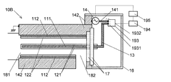
- FIG. 2 shows a schematic configuration of the plasma generation device 10A of the modification of the first embodiment.
- a power measurement unit 191 and a voltage control unit 192 are added to the plasma generation device 10 of the first embodiment.
- the power measuring unit 191 has a current input terminal 1911 and a voltage input terminal 1912.
- the connection material 13 and the one electrode 141 of the AC power supply 14 are connected to the current input terminal 1911.
- Two cables electrically connected to the connecting material 13 and the ground electrode 142 are connected to the voltage input terminal 1912. The current flowing through these two cables is sufficiently smaller than the current flowing through the connecting material 13.
- the power measuring unit 191 obtains power based on an electric signal indicating the magnitude of current and the height of voltage input from the current input terminal 1911 and the voltage input terminal 1912, and outputs an electric signal corresponding to the obtained power. It is output from the terminal 1913.
- This output terminal 1913 is connected to the voltage control unit 192.
- the voltage control unit 192 controls the voltage output from the AC power supply 14 according to the output signal from the power measurement unit 191 as described later.
- the plasma generation device 10A of the modified example generates plasma in the tube of the ground electrode 112 by the same operation as the plasma generation device 10 of the first embodiment. While the plasma is being generated, the power measuring unit 191 measures the power output by the AC power supply 14 at any time, and transmits an output signal indicating the measurement result to the voltage control unit 192.
- the voltage control unit 192 transmits a signal instructing the AC power supply 14 to lower the voltage when the value of the power output by the AC power supply 14 exceeds a predetermined range based on the signal input from the power measurement unit 191. When the value of the electric power falls below a predetermined range, a signal instructing the AC power source 14 to increase the AC voltage is transmitted. As a result, even if the AC power output from the AC power supply 14 fluctuates due to a change in the density or component of the gas between the power supply electrode 111 and the ground electrode 112, the AC power is within a predetermined range. Can be controlled as such.
- FIG. 3 shows a schematic configuration of the plasma generator 10B, which is another modification of the first embodiment.
- a current waveform acquisition unit 193, a pulse current detection unit 194, and a second voltage control unit 195 are added to the plasma generation device 10 of the first embodiment.
- the current waveform acquisition unit 193 is provided with a current input terminal 1931 and an output terminal 1932, acquires an alternating current waveform input from the current input terminal 1931, converts it into an electric signal indicating the magnitude of the current, and outputs the waveform. It is output from the terminal 1932.
- the connection material 13 and the one electrode 141 of the AC power supply 14 are connected to the current input terminal 1931.
- a pulse current detection unit 194 is connected to the output terminal 1932.
- the pulse current detection unit 194 detects a current pulse based on an electric signal input from the current waveform acquisition unit 193.
- the second voltage control unit 195 controls the voltage output from the AC power supply 14 as described later, based on the repetition frequency of the pulse of the detected current.
- the plasma generation device 10B of this modification generates plasma in the tube of the ground electrode 112 by the same operation as the plasma generation device 10 of the first embodiment. While the plasma is being generated, the current waveform acquisition unit 193 acquires an alternating current waveform at any time, and the pulse current detection unit 194 detects a pulse of the current.
- the second voltage control unit 195 is an AC power supply so that when the pulse repetition frequency of the current detected by the pulse current detection unit 194 fluctuates outside a predetermined range, the pulse repetition frequency falls within a predetermined range.
- the voltage output from 14 is increased or decreased. As a result, even if the pulse repetition frequency fluctuates due to changes in the gas density or component between the power supply electrode 111 and the ground electrode 112, the pulse repetition frequency can be controlled to be within a predetermined range. can.
- the power measurement unit 191 and the voltage control unit 192 of the plasma generation device 10A may be provided together with the current waveform acquisition unit 193, the pulse current detection unit 194 and the second voltage control unit 195 of the plasma generation device 10B. ..
- the power measuring unit 191 and the current waveform acquisition unit 193 can be used in combination.
- the voltage control unit 192 and the second voltage control unit 195 may be used in combination.
- Plasma generator of the second embodiment (2-1) Configuration of Plasma Generation Device of the Second Embodiment
- the plasma generation device of the second embodiment will be described with reference to FIGS. 4 to 6.
- the plasma generation device of the second embodiment has a plurality of power supply electrodes and a plurality of ground electrodes, respectively.
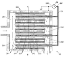
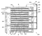
- FIG. 4 and 5 are diagrams showing a schematic configuration of the plasma generation device 20 of the second embodiment.
- FIG. 4 shows the configuration in the AA cross section shown in FIG. 5
- FIG. 5 shows the configuration in the BB cross section shown in FIG.
- a plurality of holes are provided in a block 201 made of a conductor (for example, stainless steel), and one set of a combination of a power supply electrode 211 and a ground electrode 212 is inserted into each hole.
- Each power supply electrode 211 and ground electrode 212 has the same configuration as the power supply electrode 111 and ground electrode 112 of the first embodiment. That is, the ground electrode 212 has a tubular shape, and the power supply electrode 211 is inserted into the tube of the ground electrode 212.
- the ground electrode 212 is in contact with the block 201, and the ground electrode 212 is also grounded by grounding the block 201.
- a power supply side insulating material 221 is provided on the side surface of the power supply electrode 211, and a grounding side insulating material 222 is provided on the inner surface of the tube of the grounding electrode 212.
- each power supply electrode 211 extends to the outside of the tube of each ground electrode 212 and is electrically connected to a common connecting material 23.
- the connecting material 23 is connected to one electrode 241 of the AC power supply 24.
- the other electrode 242 of the AC power supply 24 is grounded.
- the connecting material 23 may be covered with a non-contact protective cover, or the connecting material 23 may be covered with a covering material.
- the block 201 further has a gas introduction path 251 communicating with a gas introduction port 281 which is an opening at one end (left side of FIG. 4) of the ground electrode 212, and a gas discharge port which is an opening at the other end (right side of the same).
- a gas discharge path 252 communicating with 282 is provided.
- the gas introduction path 251 communicates with all of the gas introduction ports 281 of each of the plurality of ground electrodes 212, and the gas discharge path 252 communicates with all of the gas discharge ports 282 of each of the plurality of ground electrodes 212.
- FIGS. 4 and 5 show an example of having 12 sets of the power supply electrode 211 and the ground electrode 212
- the number of combinations of the power supply electrode 211 and the ground electrode 212 is not limited to this.
- Either the power supply side insulating material 221 or the ground side insulating material 222 may be omitted.
- the ground electrode 212 is provided separately from the block 201, but only the power supply electrode 211 (covered with the power supply side insulating material 221 if necessary) is inserted into the hole provided in the block 201, and the block 201 itself. May be used as a ground electrode.
- the ground-side insulating material can be formed by covering the inner surface of the hole provided in the block 201 with the insulating material.
- plasma can be generated simultaneously between a plurality of sets of power supply electrodes 211 and the ground electrode 212, so that the processing capacity of the gas to be processed can be increased.
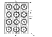
- FIG. 6 shows a plasma generation device 20A of the modification of the second embodiment in an AA cross-sectional view.
- the BB cross section of the plasma generator 20A is the same as that shown in FIG.
- the pair of the power supply electrode 211 and the ground electrode 212 adjacent to each other are inserted into the holes of the block 201 in opposite directions to each other.
- the gas inlet 281 which is the opening of the ground electrode 212 which is a linear tube is arranged on the left side of FIG. 6 in one set and on the right side of FIG. 6 in the other set.
- Each power supply electrode 211 extends to the right side of FIG. 6 (whether on the gas introduction port 281 side or the gas discharge port 282 side) to the outside of the pipe of the ground electrode 212, and is a common connecting material. It is electrically connected to 23.
- the gas inlet 281 of one set and the gas discharge port 282 of the other pair are adjacent to each other in the adjacent sets. ..
- a connection flow path 253 for connecting one set of adjacent gas introduction ports 281 and the other set of gas discharge ports 282 is provided.
- connection flow path 253 the four tubes of the ground electrode 212 shown in FIG. 6 are connected by the connection flow path 253, and one gas flow path is formed.
- Three gas flow paths consisting of a set of four tubes of the ground electrode 212 are formed in the depth direction of FIG. 6 (horizontal direction of FIG. 5).
- a hole may be provided in the block 201 so as to further connect these three gas flow paths, and one gas flow path may be formed by the entire plasma generation device 20A.
- the gas to be treated is brought into contact with the plasma for a longer period of time while suppressing the size of the ground electrode 212 in the longitudinal direction. Therefore, the content to be decomposed in the gas to be treated can be more reliably decomposed.
- Plasma generator of the third embodiment (3-1) Configuration of Plasma Generation Device of Third Embodiment
- the plasma generation device of the third embodiment will be described with reference to FIGS. 7 to 9.
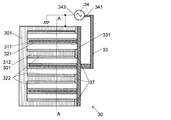
- Each of the plasma generation devices of the third embodiment has a plurality of flat plate-shaped power supply electrodes 311 and ground electrodes 312, respectively.
- FIG. 7 and 8 are diagrams showing a schematic configuration of the plasma generation device 30 of the third embodiment.
- FIG. 7 shows the configuration in the AA cross section shown in FIG. 8
- FIG. 8 shows the configuration in the BB cross section shown in FIG. 7.
- the conductor block 301 is provided with three flat plate-shaped holes arranged in the vertical direction from the right side to the left side of FIG.
- One flat plate-shaped power supply electrode 311 is inserted into each of these three holes in parallel with the flat plate having the shape of the holes.
- the upper and lower surfaces of the block 301 and the conductor of the block 301 left between the holes serve as a flat plate-shaped ground electrode 312. Therefore, in this embodiment, the flat plate-shaped power supply electrode 311 and the ground electrode 312 are alternately arranged in parallel.
- a power supply side insulating material 321 is provided on both surfaces of the power supply electrode 311 and a ground side insulating material 322 is provided on the surface of the ground electrode 312 facing the power supply electrode 311.
- a lid 331 made of a conductor.
- the lid 331 is electrically insulated from the block 301 by an insulating material 37.
- Each power electrode 311 is in contact with the lid 331.
- a rod-shaped connecting material 33 is further in contact with the lid 331.
- the connecting material 33 is connected to one electrode 341 of the AC power supply 34.
- the other electrode 342 of the AC power supply 34 is grounded.
- the connecting material 33 may be covered with a non-contact protective cover, or the connecting material 33 may be covered with a covering material.
- each power supply electrode 311 and the ground electrode 312 there is a flow path through which the gas to be processed flows.
- the left end of each power supply electrode 311 and the ground electrode 312 is a gas introduction port 381, and the right end is a gas discharge port 382.
- a gas introduction path 351 communicating with each gas introduction port 381 is provided on the left side of each power supply electrode 311 and the ground electrode 312, and a gas discharge path 352 communicating with each gas discharge port 382 is provided on the right side.
- FIGS. 7 and 8 show an example in which three sets of the power supply electrode 311 and the ground electrode 312 are provided, the number of these sets is not limited to three. Either the power supply side insulating material 321 or the ground side insulating material 322 may be omitted. Further, although a part of the block 301 is used as the ground electrode 312 in the present embodiment, the ground electrode 312 may be provided separately from the block 301.
- plasma can be generated simultaneously between a plurality of sets of power supply electrodes 311 and the ground electrode 312, so that the processing capacity of the gas to be processed can be increased.
- FIG. 9 shows a plasma generation device 30A of the modification of the third embodiment in a cross-sectional view of AA.
- the BB cross section of the plasma generator 30A is the same as that shown in FIG.
- the gas flow paths formed on both the upper and lower sides of the first power supply electrode 311 from the top of the three power supply electrodes 311 and the upper and lower sides of the second power supply electrode 311 from the top are formed.
- the gas flow paths are connected by providing a connection flow path 353 on the right side of the power supply electrode 311.
- the gas flow paths formed on both the upper and lower sides of the second power supply electrode 311 from the top and the gas flow paths formed on the upper and lower sides of the third power supply electrode 311 from the top are formed on the power supply electrodes 311. It is connected by providing a connection flow path 353 on the left side. As a result, a zigzag gas flow path is formed from the first power supply electrode 311 to the third power supply electrode 311 from the top.
- the zigzag gas flow path can be formed in the same manner when the number of the power supply electrodes is two or four or more.
- the size in the direction parallel to the power supply electrode 311 is suppressed while suppressing the size. Since the gas to be treated can be brought into contact with the plasma for a longer period of time, the inclusions to be decomposed in the gas to be treated can be more reliably decomposed.
- Voltage control unit 193 ... Current waveform acquisition unit 1931 ... Current input Terminal 1932 ... Output terminal 194 ... Pulse current detection unit 195 ... Second voltage control unit 201, 301 ... Blocks 251 and 351 ... Gas introduction path 252, 352 ... Gas discharge path 253, 353 ... Connection flow path 33 ... Connection material 331 ... Lid 37 ... Insulation material
Landscapes
- Engineering & Computer Science (AREA)
- Physics & Mathematics (AREA)
- Plasma & Fusion (AREA)
- Spectroscopy & Molecular Physics (AREA)
- Chemical & Material Sciences (AREA)
- Combustion & Propulsion (AREA)
- Mechanical Engineering (AREA)
- General Engineering & Computer Science (AREA)
- Plasma Technology (AREA)
- Processes For Solid Components From Exhaust (AREA)
- Physical Or Chemical Processes And Apparatus (AREA)
Abstract
ガス流路内を流れる気体を電離してプラズマを生成するためのガス処理装置に設けられ、漏電や不所望の放電が生じることを防ぐことができる誘電体バリア放電型のプラズマ生成装置を提供する。プラズマ生成装置(10)は、交流電源(14)と、一方がガス流路内に配置され、他方が該ガス流路を構成する導電体製の壁である、電源電極(111)及び接地電極(121)と、交流電源(14)と電源電極(111)を電気的に接続する非可撓性の接続材(13)と、電源電極(111)と接地電極(121)のうちの一方の、他方の電極に対向する側を覆う絶縁材(電源側絶縁材(121)、接地側絶縁材(122))と備える。非可撓性の接続材(13)を用いることにより、ガス流路内を流れる気体から電源電極(111)を介して接続材(13)に振動が伝わっても、接続材(13)がプラズマ生成装置(10)中の電源電極以外の部材に不意に接触又は接近することがないため、漏電や不所望の放電が生じることを防ぐことができる。
Description
本発明はプラズマ生成装置に関し、特に略大気圧中でプラズマを生成することができる誘電体バリア放電型のプラズマ生成装置に関する。
従来より、ディーゼルエンジン等から排出される排ガスを煤等の粒子状物質(particulate matter:PM)が含まれた状態で大気中に放出することを抑制するために、排ガスの流路中に、プラズマ生成装置を備える排ガス処理装置が設けられている(例えば特許文献1参照)。このような排ガスの流路中にプラズマを生成し、PMをプラズマに接触させることにより、PMを二酸化炭素等に分解する。
多くのプラズマ生成装置では真空に近いプラズマ生成室(真空容器)内でプラズマを生成するが、排ガスの流路内は真空よりも十分に高い、大気圧に近い圧力を有するため、排ガス処理装置で用いるプラズマ生成装置には略大気圧中でプラズマを生成することができる装置を用いる。そのような装置の1つに、誘電体バリア放電を用いてプラズマを生成する誘電体バリア放電型のプラズマ生成装置がある。
誘電体バリア放電型のプラズマ生成装置は、一対の電極のうちの少なくとも一方の電極の、他方の電極に対向する側に絶縁材を被覆したものである。これらの電極間を略大気圧にした状態で、周波数が数十Hz~100kHzの範囲内であって500V~10kVの範囲内の交流電圧を隣接電極間に印加すると、交流の1周期内で隣接電極間の電位差の絶対値が閾値を超えると隣接電極間に放電が生じる。この放電により、電荷が絶縁材に付着し、両電極の絶縁材間の電位差が小さくなって放電が停止する。その状態から該1周期内で隣接電極間の電位差の絶対値がさらに大きくなると再び放電が生じるが、それによってさらに電荷が絶縁材に付着して両電極の絶縁材間の電位差が小さくなり、再び放電が停止する。このように、交流電圧の1周期内で電極間の電圧の絶対値が大きくなる間に、パルス状の放電が該交流電圧の周波数よりも高い繰り返し周波数で生じる。
このような誘電体バリア放電型のプラズマ生成装置が有する一対の電極の一方を排ガス処理装置のガス流路内に配置し、他方を該ガス流路を構成する導電体製の壁とする。これにより、隣接電極間の空間であるガス流路内に放電が生じ、ガス流路内を流れる気体が電離してプラズマが生成される。そして、PMがこのプラズマに接触することにより、PMが分解される。
特許文献1に記載のプラズマ生成装置では、各電極は、交流配線を通して交流電源に、又は接地配線を通して接地に接続される。交流配線には通常、取り回しを容易にするために、可撓性を有する金属線を可撓性を有する被覆材で被覆したケーブルが用いられる。このようなケーブルは、長期間使用している間に被覆材が経年劣化してしまう。そして、ガス流路内の電極又はガス流路の壁である電極がガス流路内のガスの流れから振動を受けることにより、ケーブルにもそれが接続された電極を介して振動が伝わる。被覆材が経年劣化したケーブルがこの振動によって該ケーブルが接続された電極以外の部材に接触又は接近してしまうと、漏電又は不所望の(プラズマを生成するための放電以外の)放電が生じてしまうおそれがある。
ここでは、ディーゼルエンジン等から排出される排ガス中のPMを分解する排ガス処理装置を例に説明したが、それ以外の、ガス流路内を流れる気体を電離してプラズマを生成することによって該気体に対する処理を行うガス処理装置に設けられた誘電体バリア放電型のプラズマ生成装置においても同様の問題が生じる。
本発明が解決しようとする課題は、ガス処理装置に設けられ、漏電や不所望の放電が生じることを防ぐことができる誘電体バリア放電型のプラズマ生成装置を提供することである。
上記課題を解決するために成された本発明は、ガス流路内を流れる気体を電離してプラズマを生成するための、ガス処理装置に設けられるプラズマ生成装置であって、
a) 交流電源と、
b) 一方が前記ガス流路内に配置され、他方が該ガス流路を構成する導電体製の壁である、電源電極及び接地電極と、
c) 前記交流電源と前記電源電極を電気的に接続する非可撓性の接続材と、
d) 前記電源電極と前記接地電極のうちの一方の、他方の電極に対向する側を覆う絶縁材と
を備えることを特徴とする。
a) 交流電源と、
b) 一方が前記ガス流路内に配置され、他方が該ガス流路を構成する導電体製の壁である、電源電極及び接地電極と、
c) 前記交流電源と前記電源電極を電気的に接続する非可撓性の接続材と、
d) 前記電源電極と前記接地電極のうちの一方の、他方の電極に対向する側を覆う絶縁材と
を備えることを特徴とする。
本発明に係るプラズマ生成装置では、交流電源と電源電極を電気的に接続するために、非可撓性の接続材を用いる。ここで言う「非可撓性の」とは、容易に変形しないことをいい、さらに詳しくは、振動が加えられても弾性範囲内で振動し、当初の設置状態が維持されることをいう。すなわち、当初、他の部材等に接触しないように設置されていれば、長期間振動等を受けてもそのように他の部材に接触しない状態が維持される。従って、ガス流路内を流れる気体から電源電極(ガス流路内に配置された電極、又はガス流路を構成する導電体製の壁である電極)を介して接続材に振動が伝わっても、接続材がプラズマ生成装置中の電源電極以外の部材に不意に接触又は接近することがないため、漏電や不所望の放電が生じることを防ぐことができる。
本発明に係るプラズマ生成装置では、このように非可撓性の接続材を用いることで漏電や不所望の放電を防ぐため、接続材を被覆材で被覆する必要はない。一方、点検時等の安全性を考慮して、接続材を被覆材で被覆してもよい。あるいは、接続材と離間して該接続材を覆う保護カバーを設置してもよい。
前記絶縁材は、電源電極と接地電極のいずれか一方にのみ設けてもよいし、それらの双方に設けてもよい。
前記接地電極を接地するために、前記接続材と同様の非可撓性の接続材を用いてもよい。
前記交流電源には、従来の誘電体バリア放電型のプラズマ生成装置と同様に、周波数が数十Hz(日本の商用周波数である50Hz及び60Hzを含む)~100kHzの範囲内であって500V~10kVの範囲内の交流電圧を発生させるものを用いることができる。
本発明に係るプラズマ生成装置においてさらに、前記交流電源から出力される交流電力を測定する電力測定部と、該電力測定部で測定される交流電力に応じて該交流電力の交流電圧を制御する電圧制御部とを備えることができる。これにより、電源電極と接地電極の間の気体の密度や成分等が変化すること等によって交流電力が変動したときに、交流電力が所定の範囲内になるように制御することができる。
本発明に係るプラズマ生成装置においてさらに、前記交流電源から出力される交流電流の波形を取得する電流波形取得部と、該電流波形取得部で取得される交流電流の波形から放電によるパルス電流を検出するパルス電流検出部と、前記パルス電流検出部で検出されるパルス電流のパルス繰り返し周波数に応じて前記交流電力の交流電圧を制御する第2電圧制御部とを備えることができる。これにより、電源電極と接地電極の間の気体の密度や成分等が変化すること等によってパルス繰り返し周波数が変動したときに、パルス繰り返し周波数が所定の範囲内になるように制御することができる。
本発明に係るプラズマ生成装置において、前記電源電極と前記接地電極の組み合わせを複数組有し、該電源電極の各々に共通の接続材が接続されている、という構成を取ることができる。この構成によれば、複数組の電源電極と接地電極の間に同時にプラズマを生成することができるため、ガスの処理能力を高くすることができる。
このように電源電極と接地電極の組み合わせを複数組有する場合において、該電源電極と該接地電極のいずれか一方が直線状の管状電極であり、さらに、複数の管状電極のうちの2つを接続する接続流路を有する、という構成を取ることができる。これにより、管状電極の長手方向のサイズを抑えつつ、ガスの流路を長くすることができるため、より確実にガスの処理を行うことができる。
本発明に係るプラズマ生成装置において、前記電源電極と前記接地電極が交互に1個ずつそれぞれ複数個配置されており、該電源電極の各々に共通の接続材が接続されている、という構成を取ることができる。これにより、互いに隣接する電源電極と接地電極の間でプラズマが生成され、複数組の隣接電極間に同時にプラズマを生成することができるため、ガスの処理能力を高くすることができる。なお、各電源電極では、両隣の(すなわち2個の)接地電極との間でプラズマが生成されることとなる。
前記電源電極と前記接地電極が交互に1個ずつそれぞれ複数個配置されている場合において、該電源電極及び該接地電極が平板電極であって、さらに、該電源電極と該接地電極のいずれか一方と他方の間に形成されるガス流路につき、隣接するガス流路間を接続する接続流路を有する、という構成を取ることができる。これにより、平板電極の板に平行な方向のサイズを抑えつつ、ガスの流路を長くすることができるため、より確実にガスの処理を行うことができる。
本発明により、ガス処理装置に設けられるプラズマ生成装置において、漏電や不所望の放電が生じることを防ぐことができる。
図1~図9を用いて、本発明に係るプラズマ生成装置の実施形態を説明する。
(1) 第1実施形態のプラズマ生成装置
(1-1) 第1実施形態のプラズマ生成装置の構成
図1に、第1実施形態のプラズマ生成装置10の概略構成を示す。第1実施形態のプラズマ生成装置10は、ガス処理装置内に設けられるものであって、処理対象のガス(被処理ガス)の流路となる管を有する。この管の管壁は導電体製であって、接地されている。この管壁がプラズマ生成装置10の接地電極112に該当する。接地電極112の管内、すなわちガス流路内には、電源電極111が配置されている。本実施形態では、接地電極112の管は円筒であって、電源電極111はこの円筒の中心に配置された円柱形の導電体である。電源電極111の一方(図1の左側)の端は接地電極112の管の一方(同左側)の端まで延びており、他方(同右側)の端は接地電極112の管の他方(同右側)の端よりも外側まで延出している。
電源電極111の円柱の側面には、その全体を覆うように絶縁体(誘電体)製の電源側絶縁材121が設けられている。また、接地電極112の管の内面には、その全体を覆うように絶縁体(誘電体)製の接地側絶縁材122が設けられている。なお、本実施形態では電源側絶縁材121と接地側絶縁材122を設けたが、それらのうちのいずれか一方のみを設けるようにしてもよい。
電源電極111のうち、接地電極112の管よりも外側まで延出している部分には、導電体であって非可撓性の材料から成る棒材である接続材13の一方(図1の下側)の端が接続されている。また、プラズマ生成装置10は交流電源14を有しており、この交流電源14の一方の電極141に接続材13の他方(同上側)の端が接続されている。接続材13は、被覆材で被覆されておらず、電源電極111及び交流電源14の電極141以外の部材には接触していない。
交流電源14の他方の電極142は、接地電極112の管の周囲を覆うように形成されており、接地電極112と共に接地されている。交流電源14には、周波数が数十Hz~100kHzの範囲内であって出力電圧が500V~10kVであるものを用いる。日本の商用電源(周波数が50Hz又は60Hz、電圧が100V又は200V)を交流電源14に用いてもよい。
電源電極111、接地電極112及び接続材13の材料にはいずれも、例えば銅やステンレス鋼を用いることができる。
接続材13の外側には、該接続材13から離間してそれを覆うように、絶縁体(誘電体)の板材製の保護カバー16が設けられている。なお、点検時等に、接続材13に通電している状態で人が接続材13に触れるおそれがない場合には、保護カバー16は省略してもよい。また、保護カバー16を設ける代わりに、接続材13を被覆材で被覆してもよい。
接地電極112の管の前記他方の端には、電源電極111を通過させつつ該他方の端の開口を気密に閉鎖するフィードスルー17が設けられている。この他方の端の手前には、接地電極112の管の管壁に開口が設けられており、この開口がガス排出口182となる。接地電極112の管における前記一方の端の開口はガス導入口181となる。
(1-2) 第1実施形態のプラズマ生成装置の動作
第1実施形態のプラズマ生成装置10の動作を説明する。ガス導入口181からガス流路となる接地電極112の管内に被処理ガス(例えばディーゼルエンジンから排出される排ガス)を導入する。それと共に、交流電源14により、電源電極111と接地電極112の間に交流電圧を印加する。これにより、従来の誘電体バリア放電型のプラズマ生成装置と同様に、交流電圧の1周期内で電極間の電圧の絶対値が大きくなる間に、パルス状の放電が該交流電圧の周波数よりも高い繰り返し周波数で生じる。このパルス状の放電によって、接地電極112の管内を流れる被処理ガスが電離してプラズマが生成され、このプラズマに接触したPM等の分解対象の含有物が分解される。このようにプラズマによる処理がなされた被処理ガスは、ガス排出口182から排出される。
第1実施形態のプラズマ生成装置10の動作を説明する。ガス導入口181からガス流路となる接地電極112の管内に被処理ガス(例えばディーゼルエンジンから排出される排ガス)を導入する。それと共に、交流電源14により、電源電極111と接地電極112の間に交流電圧を印加する。これにより、従来の誘電体バリア放電型のプラズマ生成装置と同様に、交流電圧の1周期内で電極間の電圧の絶対値が大きくなる間に、パルス状の放電が該交流電圧の周波数よりも高い繰り返し周波数で生じる。このパルス状の放電によって、接地電極112の管内を流れる被処理ガスが電離してプラズマが生成され、このプラズマに接触したPM等の分解対象の含有物が分解される。このようにプラズマによる処理がなされた被処理ガスは、ガス排出口182から排出される。
このように処理される被処理ガスが接地電極112の管内を流れる際に、ガス流路内の電源電極111は被処理ガスの流れから振動を受ける。そして、この振動は、電源電極111から接続材13に伝わる。
従来のガス処理装置に設けられたプラズマ生成装置では、可撓性を有する金属線を可撓性を有する被覆材で被覆したケーブルによって電源電極と交流電源が接続されていたため、被覆材が経年劣化したケーブルが電源電極から受ける振動によってプラズマ生成装置のうちの電極以外の部材に接触又は接近し、漏電や不所望の放電が生じてしまうおそれがあった。それに対して本実施形態のプラズマ生成装置10では、非可撓性の接続材13によって電源電極111と交流電源14を電気的に接続しているため、電源電極111から振動を受けても接続材13がプラズマ生成装置10のうちの電極以外の部材に接触あるいは接近することがなく、漏電や不所望の放電が生じることを防ぐことができる。
(1-3) 第1実施形態のプラズマ生成装置の変形例
図2に、第1実施形態の変形例のプラズマ生成装置10Aの概略構成を示す。このプラズマ生成装置10Aは、上記第1実施形態のプラズマ生成装置10に、電力測定部191及び電圧制御部192が追設されたものである。
図2に、第1実施形態の変形例のプラズマ生成装置10Aの概略構成を示す。このプラズマ生成装置10Aは、上記第1実施形態のプラズマ生成装置10に、電力測定部191及び電圧制御部192が追設されたものである。
電力測定部191は電流入力端子1911及び電圧入力端子1912を有する。電流入力端子1911には接続材13及び交流電源14の前記一方の電極141を接続する。電圧入力端子1912には、接続材13及び接地電極142にそれぞれ電気的に接続された2本のケーブルを接続する。なお、これら2本のケーブルに流れる電流は接続材13に流れる電流よりも十分に小さい。電力測定部191は、電流入力端子1911及び電圧入力端子1912から入力される、電流の大きさ及び電圧の高さを示す電気信号に基づいて電力を求め、求めた電力に対応する電気信号を出力端子1913から出力するものである。この出力端子1913は電圧制御部192に接続されている。電圧制御部192は、電力測定部191からの出力信号に応じて、後述のように交流電源14から出力される電圧を制御するものである。
変形例のプラズマ生成装置10Aは、上記第1実施形態のプラズマ生成装置10と同様の動作によって接地電極112の管内にプラズマを生成する。プラズマを生成している間、随時、電力測定部191は交流電源14が出力する電力を測定し、その測定結果を示す出力信号を電圧制御部192に送信する。電圧制御部192は、電力測定部191から入力された信号に基づいて、交流電源14が出力する電力の値が所定の範囲を上回ったときには交流電源14に電圧を低くさせる指示の信号を送信し、電力の値が所定の範囲を下回ったときには交流電源14に交流電圧を高くさせる指示の信号を送信する。これにより、電源電極111と接地電極112の間の気体の密度や成分等が変化すること等によって交流電源14から出力される交流電力が変動しても、該交流電力が所定の範囲内となるように制御することができる。
図3に、第1実施形態の他の変形例であるプラズマ生成装置10Bの概略構成を示す。このプラズマ生成装置10Bは、上記第1実施形態のプラズマ生成装置10に、電流波形取得部193、パルス電流検出部194及び第2電圧制御部195が追設されたものである。
電流波形取得部193は、電流入力端子1931と出力端子1932が設けられており、電流入力端子1931から入力される交流電流の波形を取得し、電流の大きさを示す電気信号に変換して出力端子1932から出力するものである。電流入力端子1931には接続材13及び交流電源14の前記一方の電極141を接続する。出力端子1932にはパルス電流検出部194を接続する。パルス電流検出部194は、電流波形取得部193から入力された電気信号に基づいて、電流のパルスを検出するものである。第2電圧制御部195は、検出された電流のパルスの繰り返し周波数に基づいて、後述のように交流電源14から出力される電圧を制御するものである。
この変形例のプラズマ生成装置10Bは、上記第1実施形態のプラズマ生成装置10と同様の動作によって接地電極112の管内にプラズマを生成する。プラズマを生成している間、随時、電流波形取得部193は交流電流の波形を取得し、パルス電流検出部194は電流のパルスを検出する。第2電圧制御部195は、パルス電流検出部194で検出された電流のパルスの繰り返し周波数が所定の範囲外に変動したときに、該パルス繰り返し周波数が所定の範囲内になるように、交流電源14から出力される電圧を高く又は低くする。これにより、電源電極111と接地電極112の間の気体の密度や成分等が変化すること等によってパルス繰り返し周波数が変動しても、パルス繰り返し周波数が所定の範囲内になるように制御することができる。
なお、プラズマ生成装置10Aが有する電力測定部191及び電圧制御部192と、プラズマ生成装置10Bが有する電流波形取得部193、パルス電流検出部194及び第2電圧制御部195とを併設してもよい。この場合、電力測定部191として、電流入力端子1911から入力される交流電流の波形を取得する機能を有するものを用いれば、電力測定部191と電流波形取得部193を兼用することができる。また、電圧制御部192と第2電圧制御部195を兼用するようにしてもよい。
(2) 第2実施形態のプラズマ生成装置
(2-1) 第2実施形態のプラズマ生成装置の構成
図4~図6を用いて、第2実施形態のプラズマ生成装置について説明する。第2実施形態のプラズマ生成装置は、電源電極及び接地電極をそれぞれ複数個有する。
(2-1) 第2実施形態のプラズマ生成装置の構成
図4~図6を用いて、第2実施形態のプラズマ生成装置について説明する。第2実施形態のプラズマ生成装置は、電源電極及び接地電極をそれぞれ複数個有する。
図4及び図5は、第2実施形態のプラズマ生成装置20の概略構成を示す図である。図4は図5中に示したA-A断面での構成を示し、図5は図4中に示したB-B断面での構成を示している。
このプラズマ生成装置20では、導電体(例えばステンレス鋼)製のブロック201に孔を複数本設け、各孔に電源電極211と接地電極212を組み合わせたものを1組ずつ挿入している。各電源電極211及び接地電極212は、第1実施形態の電源電極111及び接地電極112と同様の構成を有する。すなわち、接地電極212は管状の形状を有し、電源電極211は接地電極212の管内に挿入されている。接地電極212はブロック201に接触しており、ブロック201が接地されることにより接地電極212も接地されている。電源電極211の側面には電源側絶縁材221が、接地電極212の管の内面には接地側絶縁材222が、それぞれ設けられている。
各電源電極211の一方の端は各接地電極212の管よりも外側まで延びており、共通の接続材23に電気的に接続されている。接続材23は、交流電源24の一方の電極241に接続されている。交流電源24の他方の電極242は接地されている。なお、図4に示した例では設けていないが、接続材23を非接触の保護カバーで覆ったり、接続材23を被覆材で覆ってもよい。
ブロック201にはさらに、接地電極212の一方(図4の左側)の端の開口であるガス導入口281と連通するガス導入路251、及び他方(同右側)の端の開口であるガス排出口282と連通するガス排出路252が設けられている。ガス導入路251は複数の接地電極212が各々有するガス導入口281の全てと連通し、ガス排出路252は複数の接地電極212が各々有するガス排出口282の全てと連通している。
なお、図4及び図5では電源電極211と接地電極212を12組有する例を示したが、電源電極211と接地電極212の組み合わせの数はこれには限定されない。電源側絶縁材221と接地側絶縁材222のいずれか一方は省略してもよい。さらに、本実施形態ではブロック201とは別に接地電極212を設けたが、ブロック201に設けた孔に電源電極211(必要に応じて電源側絶縁材221で被覆)のみを挿入し、ブロック201自体を接地電極として用いてもよい。その場合には、ブロック201に設けた孔の内面を絶縁材で覆うことにより接地側絶縁材を形成することができる。
(2-2) 第2実施形態のプラズマ生成装置の動作
第2実施形態のプラズマ生成装置20の動作を説明する。被処理ガスをガス導入路251に導入すると、被処理ガスは、複数設けられた接地電極212の管の各々に分かれて該管内を流れ、共通のガス排出路252から排出される。その間、交流電源24により、各電源電極211と接地電極212の間に交流電圧を印加する。これにより、第1実施形態の場合と同様に、各電源電極211と接地電極212の間にパルス状の放電が生じ、被処理ガスが電離してプラズマが生成される。このプラズマに接触した分解対象の含有物が分解される。
第2実施形態のプラズマ生成装置20の動作を説明する。被処理ガスをガス導入路251に導入すると、被処理ガスは、複数設けられた接地電極212の管の各々に分かれて該管内を流れ、共通のガス排出路252から排出される。その間、交流電源24により、各電源電極211と接地電極212の間に交流電圧を印加する。これにより、第1実施形態の場合と同様に、各電源電極211と接地電極212の間にパルス状の放電が生じ、被処理ガスが電離してプラズマが生成される。このプラズマに接触した分解対象の含有物が分解される。
第2実施形態のプラズマ生成装置20によれば、複数組の電源電極211と接地電極212の間に同時にプラズマを生成することができるため、被処理ガスの処理能力を高くすることができる。
(2-3) 第2実施形態のプラズマ生成装置の変形例
図6に、第2実施形態の変形例のプラズマ生成装置20AをA-A断面図で示す。プラズマ生成装置20AのB-B断面は図5に示したものと同様である。このプラズマ生成装置20Aでは、隣接する電源電極211と接地電極212の組同士では互いに逆向きにブロック201の孔に挿入されている。具体的には、直線状の管である接地電極212の開口であるガス導入口281が、一方の組では図6の左側に配置され、他方の組では図6の右側に配置されている。各電源電極211は、図6の右側(ガス導入口281側であるかガス排出口282側であるかを問わず)に、接地電極212の管よりも外側まで延びており、共通の接続材23に電気的に接続されている。
図6に、第2実施形態の変形例のプラズマ生成装置20AをA-A断面図で示す。プラズマ生成装置20AのB-B断面は図5に示したものと同様である。このプラズマ生成装置20Aでは、隣接する電源電極211と接地電極212の組同士では互いに逆向きにブロック201の孔に挿入されている。具体的には、直線状の管である接地電極212の開口であるガス導入口281が、一方の組では図6の左側に配置され、他方の組では図6の右側に配置されている。各電源電極211は、図6の右側(ガス導入口281側であるかガス排出口282側であるかを問わず)に、接地電極212の管よりも外側まで延びており、共通の接続材23に電気的に接続されている。
上記のように各電源電極211と接地電極212の組が配置されていることにより、隣接する組同士では、一方の組のガス導入口281と他方の組のガス排出口282が隣接している。ブロック201内には、これら隣接する一方の組のガス導入口281と他方の組のガス排出口282を接続する接続流路253が設けられている。
これにより、図6に4個示された接地電極212の管が接続流路253で接続され、1つのガス流路が形成される。これら4個1組の接地電極212の管から成るガス流路が、図6の奥行き方向(図5の横方向)に3本形成されることとなる。なお、これら3本のガス流路をさらに接続するようにブロック201に孔を設け、プラズマ生成装置20A全体で1本のガス流路を形成するようにしてもよい。
このように、複数本の接地電極212の管を接続してガス流路を形成することにより、接地電極212の長手方向のサイズを抑えつつ、より長い時間、被処理ガスをプラズマに接触させることができるため、被処理ガス中の分解対象の含有物をより確実に分解することができる。
(3) 第3実施形態のプラズマ生成装置
(3-1) 第3実施形態のプラズマ生成装置の構成
図7~図9を用いて、第3実施形態のプラズマ生成装置について説明する。第3実施形態のプラズマ生成装置は、いずれも平板状である電源電極311及び接地電極312をそれぞれ複数個有する。
(3-1) 第3実施形態のプラズマ生成装置の構成
図7~図9を用いて、第3実施形態のプラズマ生成装置について説明する。第3実施形態のプラズマ生成装置は、いずれも平板状である電源電極311及び接地電極312をそれぞれ複数個有する。
図7及び図8は、第3実施形態のプラズマ生成装置30の概略構成を示す図である。図7は図8中に示したA-A断面での構成を示し、図8は図7中に示したB-B断面での構成を示している。
プラズマ生成装置30では、導電体製のブロック301に、図8の右側から左側に向かって平板状の孔が3個、縦方向に並んで設けられている。これら3個の孔のそれぞれに、平板状の電源電極311が1個ずつ、前記孔の形状である平板に平行に挿入されている。ブロック301の上面及び下面、並びに各孔の間に残されたブロック301の導電体は、平板状の接地電極312としての役割を有する。従って、この実施形態では、平板状の電源電極311と接地電極312が交互に平行に配置されている。電源電極311の両面には電源側絶縁材321が、接地電極312の電源電極311と対向する面には接地側絶縁材322が、それぞれ設けられている。また、これら孔の開口は導電体製の蓋331で気密に閉鎖されている。蓋331はブロック301とは絶縁材37によって電気的に絶縁されている。各電源電極311は蓋331に接触している。蓋331にはさらに棒状の接続材33が接触している。接続材33は交流電源34の一方の電極341に接続されている。交流電源34の他方の電極342は接地されている。なお、接続材33を非接触の保護カバーで覆ったり、接続材33を被覆材で覆ってもよい。
各電源電極311及び接地電極312の間は被処理ガスが流れる流路となっている。図7において、各電源電極311及び接地電極312の左端はガス導入口381、右端はガス排出口382となっている。各電源電極311及び接地電極312の左側には各ガス導入口381と連通するガス導入路351が設けられ、右側には各ガス排出口382と連通するガス排出路352が設けられている。
なお、図7及び図8では電源電極311と接地電極312を3組設けた例を示したが、それらの組の数は3組には限定されない。電源側絶縁材321と接地側絶縁材322のいずれか一方は省略してもよい。さらに、本実施形態ではブロック301の一部を接地電極312として用いているが、ブロック301とは別に接地電極312を設けてもよい。
(3-2) 第3実施形態のプラズマ生成装置の動作
第3実施形態のプラズマ生成装置30の動作を説明する。被処理ガスをガス導入路351に導入すると、被処理ガスは、複数形成されている電源電極311と接地電極312の間のガス流路の各々に分かれて流れ、共通のガス排出路352から排出される。その間、交流電源34により、各電源電極311と接地電極312の間に交流電圧を印加する。これにより、第1及び第2実施形態の場合と同様に、各電源電極311と接地電極312の間にパルス状の放電が生じ、被処理ガスが電離してプラズマが生成される。このプラズマに接触した分解対象の含有物が分解される。
第3実施形態のプラズマ生成装置30の動作を説明する。被処理ガスをガス導入路351に導入すると、被処理ガスは、複数形成されている電源電極311と接地電極312の間のガス流路の各々に分かれて流れ、共通のガス排出路352から排出される。その間、交流電源34により、各電源電極311と接地電極312の間に交流電圧を印加する。これにより、第1及び第2実施形態の場合と同様に、各電源電極311と接地電極312の間にパルス状の放電が生じ、被処理ガスが電離してプラズマが生成される。このプラズマに接触した分解対象の含有物が分解される。
第3実施形態のプラズマ生成装置30によれば、複数組の電源電極311と接地電極312の間に同時にプラズマを生成することができるため、被処理ガスの処理能力を高くすることができる。
(3-3) 第3実施形態のプラズマ生成装置の変形例
図9に、第3実施形態の変形例のプラズマ生成装置30AをA-A断面図で示す。プラズマ生成装置30AのB-B断面は図8に示したものと同様である。このプラズマ生成装置30Aでは、3枚の電源電極311のうち上から1枚目の電源電極311の上下両側に形成されたガス流路と、上から2枚目の電源電極311の上下両側に形成されたガス流路を、それら電源電極311の右側に接続流路353を設けることにより接続している。同様に、上から2枚目の電源電極311の上下両側に形成されたガス流路と、上から3枚目の電源電極311の上下両側に形成されたガス流路を、それら電源電極311の左側に接続流路353を設けることにより接続している。これにより、上から1枚目の電源電極311から3枚目の電源電極311に向かってジグザグのガス流路が形成される。なお、図9の例では電源電極311が3枚の場合について説明したが、2枚あるいは4枚以上の場合にも同様にしてジグザグのガス流路を形成することができる。
図9に、第3実施形態の変形例のプラズマ生成装置30AをA-A断面図で示す。プラズマ生成装置30AのB-B断面は図8に示したものと同様である。このプラズマ生成装置30Aでは、3枚の電源電極311のうち上から1枚目の電源電極311の上下両側に形成されたガス流路と、上から2枚目の電源電極311の上下両側に形成されたガス流路を、それら電源電極311の右側に接続流路353を設けることにより接続している。同様に、上から2枚目の電源電極311の上下両側に形成されたガス流路と、上から3枚目の電源電極311の上下両側に形成されたガス流路を、それら電源電極311の左側に接続流路353を設けることにより接続している。これにより、上から1枚目の電源電極311から3枚目の電源電極311に向かってジグザグのガス流路が形成される。なお、図9の例では電源電極311が3枚の場合について説明したが、2枚あるいは4枚以上の場合にも同様にしてジグザグのガス流路を形成することができる。
このようなジグザグのガス流路に被処理ガスを流しつつ、各電源電極311と接地電極312の間にパルス状の放電を生成することにより、電源電極311に平行な方向のサイズを抑えつつ、より長い時間、被処理ガスをプラズマに接触させることができるため、被処理ガス中の分解対象の含有物をより確実に分解することができる。
以上、本発明の実施形態及び変形例を説明したが、上に述べた例以外にも、例えば複数の実施形態及び/又は変形例を組み合わせたり、本発明の主旨の範囲内で更なる構成要素の追加及び/又は変更を行うことも可能である。
10、10A、10B、20、20A、30、30A…プラズマ生成装置
111、211、311…電源電極
112、212、312…接地電極
121、221、321…電源側絶縁材
122、222、322…接地側絶縁材
13、23、33…接続材
14、24、34…交流電源
141、241、341…交流電源の電極
142、242、342…交流電源の接地電極
16…保護カバー
17…フィードスルー
181、281、381…ガス導入口
182、282、382…ガス排出口
191…電力測定部
1911…電流入力端子
1912…電圧入力端子
1913…出力端子
192…電圧制御部
193…電流波形取得部
1931…電流入力端子
1932…出力端子
194…パルス電流検出部
195…第2電圧制御部
201、301…ブロック
251、351…ガス導入路
252、352…ガス排出路
253、353…接続流路
33…接続材
331…蓋
37…絶縁材
Claims (8)
- ガス流路内を流れる気体を電離してプラズマを生成するための、ガス処理装置に設けられるプラズマ生成装置であって、
a) 交流電源と、
b) 一方が前記ガス流路内に配置され、他方が該ガス流路を構成する導電体製の壁である、電源電極及び接地電極と、
c) 前記交流電源と前記電源電極を電気的に接続する非可撓性の接続材と、
d) 前記電源電極と前記接地電極のうちの一方の、他方の電極に対向する側を覆う絶縁材と
を備えることを特徴とするプラズマ生成装置。 - さらに、接続材と離間して該接続材を覆う保護カバーを備えることを特徴とする請求項1に記載のプラズマ生成装置。
- さらに、
前記交流電源から出力される交流電力を測定する電力測定部と、
前記電力測定部で測定される交流電力に応じて該交流電力の交流電圧を制御する電圧制御部と
を備えることを特徴とする請求項1又は2に記載のプラズマ生成装置。 - さらに、
前記交流電源から出力される交流電流の波形を取得する電流波形取得部と、
前記電流波形測定部で測定される交流電流の波形から放電によるパルス電流を検出するパルス電流検出部と、
前記パルス電流検出部で検出されるパルス電流のパルス繰り返し周波数に応じて前記交流電力の交流電圧を制御する第2電圧制御部と
を備えることを特徴とする請求項1~3のいずれかに記載のプラズマ生成装置。 - 前記電源電極と前記接地電極の組み合わせを複数組有し、該電源電極の各々に共通の接続材が接続されていることを特徴とする請求項1~4のいずれかに記載のプラズマ生成装置。
- 前記電源電極と前記接地電極のいずれか一方が直線状の管状電極であり、
複数の前記管状電極が互いに平行に配置され、
さらに、隣接する前記管状電極の隣接する開口同士を接続する接続流路を有する
ことを特徴とする請求項5に記載のプラズマ生成装置。 - 前記電源電極と前記接地電極が交互に1個ずつそれぞれ複数個配置されており、
該電源電極の各々に共通の接続材が接続されている
ことを特徴とする請求項1~4のいずれかに記載のプラズマ生成装置。 - 前記電源電極及び前記接地電極が平板電極であり、
さらに、該電源電極と該接地電極のいずれか一方と他方の間に形成されるガス流路につき、隣接するガス流路間を接続する接続流路を有する
ことを特徴とする請求項7に記載のプラズマ生成装置。
Priority Applications (3)
| Application Number | Priority Date | Filing Date | Title |
|---|---|---|---|
| CN202180026077.4A CN115399076A (zh) | 2020-05-11 | 2021-05-07 | 等离子生成装置 |
| US17/920,506 US11785701B2 (en) | 2020-05-11 | 2021-05-07 | Plasma generator |
| EP21805021.9A EP4152897A4 (en) | 2020-05-11 | 2021-05-07 | PLASMA GENERATION DEVICE |
Applications Claiming Priority (2)
| Application Number | Priority Date | Filing Date | Title |
|---|---|---|---|
| JP2020083481A JP7417262B2 (ja) | 2020-05-11 | 2020-05-11 | プラズマ生成装置 |
| JP2020-083481 | 2020-05-11 |
Publications (1)
| Publication Number | Publication Date |
|---|---|
| WO2021230174A1 true WO2021230174A1 (ja) | 2021-11-18 |
Family
ID=78510507
Family Applications (1)
| Application Number | Title | Priority Date | Filing Date |
|---|---|---|---|
| PCT/JP2021/017603 Ceased WO2021230174A1 (ja) | 2020-05-11 | 2021-05-07 | プラズマ生成装置 |
Country Status (6)
| Country | Link |
|---|---|
| US (1) | US11785701B2 (ja) |
| EP (1) | EP4152897A4 (ja) |
| JP (1) | JP7417262B2 (ja) |
| CN (1) | CN115399076A (ja) |
| TW (1) | TWI865779B (ja) |
| WO (1) | WO2021230174A1 (ja) |
Citations (8)
| Publication number | Priority date | Publication date | Assignee | Title |
|---|---|---|---|---|
| JP2006510187A (ja) * | 2002-12-13 | 2006-03-23 | ブルー プラネット カンパニー リミテッド | プラズマ反応器及びそれに利用される電極プレート |
| WO2009091065A1 (ja) * | 2008-01-18 | 2009-07-23 | Kyocera Corporation | プラズマ発生体、プラズマ発生体を用いた放電装置および反応装置 |
| JP2009535208A (ja) * | 2006-05-04 | 2009-10-01 | コリア インスティテュート オブ マシーナリー アンド マテリアルズ | 平板型低温プラズマ反応器{FlattypePlasmaReactor} |
| US20100134947A1 (en) * | 2007-01-25 | 2010-06-03 | Ion A-Z, Llc | Fluid cooled electrical capacitor and methods of making and using |
| JP2017073375A (ja) * | 2016-03-01 | 2017-04-13 | アルファ株式会社 | プラズマ処理装置及びプラズマトーチ |
| JP2017107781A (ja) * | 2015-12-11 | 2017-06-15 | 日本特殊陶業株式会社 | プラズマリアクタ及び積層体用クランプ |
| JP2018071403A (ja) | 2016-10-27 | 2018-05-10 | ダイハツ工業株式会社 | 排気ガス浄化装置 |
| WO2018205758A1 (zh) * | 2017-05-10 | 2018-11-15 | 武汉凯迪电力环保有限公司 | 一种网孔形沿面放电等离子体产生氧活性物质的装置 |
Family Cites Families (17)
| Publication number | Priority date | Publication date | Assignee | Title |
|---|---|---|---|---|
| DE19635232A1 (de) * | 1996-08-30 | 1998-03-05 | Siemens Ag | Verfahren und Vorrichtung zur plasmachemischen Zersetzung und/oder Vernichtung von Schadstoffen |
| US20050214181A1 (en) * | 2004-03-26 | 2005-09-29 | Canon Kabushiki Kaisha | Dielectric, gas treatment apparatus using the same, and plasma generator |
| JP2007116622A (ja) * | 2005-10-24 | 2007-05-10 | Seiko Instruments Inc | 圧電振動子とその製造方法、表面実装型圧電振動子とその製造方法、発振器、電子機器及び電波時計 |
| CN103763846B (zh) * | 2006-02-17 | 2016-08-31 | 海别得公司 | 接触启动式等离子弧焊炬和用于该焊炬的电极、接触元件 |
| US7588413B2 (en) * | 2006-11-30 | 2009-09-15 | General Electric Company | Upstream plasma shielded film cooling |
| JP5378800B2 (ja) * | 2006-12-18 | 2013-12-25 | シーマ電子株式会社 | リードフレーム、その製造方法及びそのリードフレームを搭載した半導体装置 |
| US7732728B2 (en) * | 2007-01-17 | 2010-06-08 | Lam Research Corporation | Apparatuses for adjusting electrode gap in capacitively-coupled RF plasma reactor |
| US20150343109A1 (en) * | 2014-04-03 | 2015-12-03 | Novaerus Patent Limited | Coil Assembly for Plasma Generation |
| KR20150143075A (ko) * | 2014-06-13 | 2015-12-23 | (주)신영에어텍 | 유전체 장벽 방전을 이용한 공기정화장치 |
| US9084334B1 (en) * | 2014-11-10 | 2015-07-14 | Illinois Tool Works Inc. | Balanced barrier discharge neutralization in variable pressure environments |
| WO2016084181A1 (ja) * | 2014-11-27 | 2016-06-02 | 三菱電機株式会社 | オゾン発生装置 |
| DK3148027T3 (da) * | 2015-09-25 | 2020-03-23 | Abb Schweiz Ag | Kabelforskruning til forbindelse af et højspændingskabel til en højspændingskomponent |
| KR20190133276A (ko) * | 2017-04-21 | 2019-12-02 | 어플라이드 머티어리얼스, 인코포레이티드 | 개선된 전극 조립체 |
| CN206806687U (zh) * | 2017-06-21 | 2017-12-26 | 欧普照明股份有限公司 | 转接器、光源装置和照明设备 |
| CN208141971U (zh) * | 2017-12-27 | 2018-11-23 | 特变电工衡阳变压器有限公司 | 低损耗、低噪声,抗突发短路的配电变压器 |
| WO2019154245A1 (zh) * | 2018-02-09 | 2019-08-15 | 中国石油化工股份有限公司 | 低温等离子体反应设备和分解硫化氢的方法 |
| US20240066161A1 (en) * | 2021-08-09 | 2024-02-29 | TellaPure, LLC | Methods and apparatus for generating atmospheric pressure, low temperature plasma |
-
2020
- 2020-05-11 JP JP2020083481A patent/JP7417262B2/ja active Active
-
2021
- 2021-05-07 EP EP21805021.9A patent/EP4152897A4/en active Pending
- 2021-05-07 CN CN202180026077.4A patent/CN115399076A/zh active Pending
- 2021-05-07 WO PCT/JP2021/017603 patent/WO2021230174A1/ja not_active Ceased
- 2021-05-07 US US17/920,506 patent/US11785701B2/en active Active
- 2021-05-11 TW TW110116888A patent/TWI865779B/zh active
Patent Citations (8)
| Publication number | Priority date | Publication date | Assignee | Title |
|---|---|---|---|---|
| JP2006510187A (ja) * | 2002-12-13 | 2006-03-23 | ブルー プラネット カンパニー リミテッド | プラズマ反応器及びそれに利用される電極プレート |
| JP2009535208A (ja) * | 2006-05-04 | 2009-10-01 | コリア インスティテュート オブ マシーナリー アンド マテリアルズ | 平板型低温プラズマ反応器{FlattypePlasmaReactor} |
| US20100134947A1 (en) * | 2007-01-25 | 2010-06-03 | Ion A-Z, Llc | Fluid cooled electrical capacitor and methods of making and using |
| WO2009091065A1 (ja) * | 2008-01-18 | 2009-07-23 | Kyocera Corporation | プラズマ発生体、プラズマ発生体を用いた放電装置および反応装置 |
| JP2017107781A (ja) * | 2015-12-11 | 2017-06-15 | 日本特殊陶業株式会社 | プラズマリアクタ及び積層体用クランプ |
| JP2017073375A (ja) * | 2016-03-01 | 2017-04-13 | アルファ株式会社 | プラズマ処理装置及びプラズマトーチ |
| JP2018071403A (ja) | 2016-10-27 | 2018-05-10 | ダイハツ工業株式会社 | 排気ガス浄化装置 |
| WO2018205758A1 (zh) * | 2017-05-10 | 2018-11-15 | 武汉凯迪电力环保有限公司 | 一种网孔形沿面放电等离子体产生氧活性物质的装置 |
Non-Patent Citations (1)
| Title |
|---|
| See also references of EP4152897A4 |
Also Published As
| Publication number | Publication date |
|---|---|
| CN115399076A (zh) | 2022-11-25 |
| TWI865779B (zh) | 2024-12-11 |
| US20230143330A1 (en) | 2023-05-11 |
| JP2021180081A (ja) | 2021-11-18 |
| EP4152897A1 (en) | 2023-03-22 |
| TW202143326A (zh) | 2021-11-16 |
| JP7417262B2 (ja) | 2024-01-18 |
| EP4152897A4 (en) | 2023-11-08 |
| US11785701B2 (en) | 2023-10-10 |
Similar Documents
| Publication | Publication Date | Title |
|---|---|---|
| US6204605B1 (en) | Electrodeless discharge at atmospheric pressure | |
| US5490973A (en) | Pulsed corona reactor system for abatement of pollution by hazardous agents | |
| EP0719077A1 (en) | Method and apparatus for determining of absolute plasma parameters | |
| US20170062183A1 (en) | Plasma generation apparatus | |
| Mikropoulos et al. | Negative DC corona inception in coaxial cylinders under variable atmospheric conditions: A comparison with positive corona | |
| JP2008226647A (ja) | イオン生成装置 | |
| JP7417262B2 (ja) | プラズマ生成装置 | |
| KR20200113165A (ko) | 고전압 또는 고전계강도 발생 장치 | |
| RU2649652C1 (ru) | Емкостной делитель напряжения | |
| US6033565A (en) | System for treating gases or fluids with pulsed corona discharges | |
| US10317454B2 (en) | Electric arc detection | |
| KR101333178B1 (ko) | 유입변압기 진단 기법을 이용한 부분방전 진단방법 | |
| KR101333179B1 (ko) | 유입변압기 진단 기법을 이용한 부분방전 진단장치 | |
| El Dein et al. | Experimental and simulation study of V–I characteristics of wire–plate electrostatic precipitators under clean air conditions | |
| JP2009238377A (ja) | 放電装置 | |
| JP7289403B2 (ja) | ガス放電を生成する装置 | |
| JP4304342B2 (ja) | 大気圧コロナ放電発生装置 | |
| JP6666599B2 (ja) | 基板処理装置 | |
| CN111487453B (zh) | 一种高压电气信号真空馈通装置及电位计 | |
| TWI649769B (zh) | Wire and laser device | |
| JPS5828186A (ja) | 火花放電装置 | |
| JP6269556B2 (ja) | センサ及び部分放電検出装置 | |
| GB2337153A (en) | Detecting ions, e.g. arising from alpha particles | |
| US20100290171A1 (en) | Method and device for producing a bipolar ionic atmosphere using a dielectric barrier discharge | |
| Stishkov et al. | Barrier effect on the corona discharge form and structure in the air |
Legal Events
| Date | Code | Title | Description |
|---|---|---|---|
| 121 | Ep: the epo has been informed by wipo that ep was designated in this application |
Ref document number: 21805021 Country of ref document: EP Kind code of ref document: A1 |
|
| NENP | Non-entry into the national phase |
Ref country code: DE |
|
| ENP | Entry into the national phase |
Ref document number: 2021805021 Country of ref document: EP Effective date: 20221212 |