WO2021230196A1 - Outil de moussage, comprenant un ressort hélicoïdal avec un diamètre d'enroulement constant et un pas variable pouvant se déplacer librement à l'intérieur du récipient, et procédé d'utilisation de celui-ci - Google Patents
Outil de moussage, comprenant un ressort hélicoïdal avec un diamètre d'enroulement constant et un pas variable pouvant se déplacer librement à l'intérieur du récipient, et procédé d'utilisation de celui-ci Download PDFInfo
- Publication number
- WO2021230196A1 WO2021230196A1 PCT/JP2021/017687 JP2021017687W WO2021230196A1 WO 2021230196 A1 WO2021230196 A1 WO 2021230196A1 JP 2021017687 W JP2021017687 W JP 2021017687W WO 2021230196 A1 WO2021230196 A1 WO 2021230196A1
- Authority
- WO
- WIPO (PCT)
- Prior art keywords
- coil spring
- whisk
- vertical
- liquid material
- opening
- Prior art date
- Legal status (The legal status is an assumption and is not a legal conclusion. Google has not performed a legal analysis and makes no representation as to the accuracy of the status listed.)
- Ceased
Links
Images










Classifications
-
- B—PERFORMING OPERATIONS; TRANSPORTING
- B01—PHYSICAL OR CHEMICAL PROCESSES OR APPARATUS IN GENERAL
- B01F—MIXING, e.g. DISSOLVING, EMULSIFYING OR DISPERSING
- B01F35/00—Accessories for mixers; Auxiliary operations or auxiliary devices; Parts or details of general application
- B01F35/30—Driving arrangements; Transmissions; Couplings; Brakes
- B01F35/32—Driving arrangements
- B01F35/32005—Type of drive
- B01F35/3202—Hand driven
- B01F35/32021—Shaking by hand a portable receptacle or stirrer for mixing
-
- A—HUMAN NECESSITIES
- A47—FURNITURE; DOMESTIC ARTICLES OR APPLIANCES; COFFEE MILLS; SPICE MILLS; SUCTION CLEANERS IN GENERAL
- A47J—KITCHEN EQUIPMENT; COFFEE MILLS; SPICE MILLS; APPARATUS FOR MAKING BEVERAGES
- A47J43/00—Implements for preparing or holding food, not provided for in other groups of this subclass
- A47J43/10—Egg-whisks; Cream-beaters, i.e. hand implements or hand-driven devices
-
- B—PERFORMING OPERATIONS; TRANSPORTING
- B01—PHYSICAL OR CHEMICAL PROCESSES OR APPARATUS IN GENERAL
- B01F—MIXING, e.g. DISSOLVING, EMULSIFYING OR DISPERSING
- B01F23/00—Mixing according to the phases to be mixed, e.g. dispersing or emulsifying
- B01F23/20—Mixing gases with liquids
-
- B—PERFORMING OPERATIONS; TRANSPORTING
- B01—PHYSICAL OR CHEMICAL PROCESSES OR APPARATUS IN GENERAL
- B01F—MIXING, e.g. DISSOLVING, EMULSIFYING OR DISPERSING
- B01F23/00—Mixing according to the phases to be mixed, e.g. dispersing or emulsifying
- B01F23/40—Mixing liquids with liquids; Emulsifying
-
- B—PERFORMING OPERATIONS; TRANSPORTING
- B01—PHYSICAL OR CHEMICAL PROCESSES OR APPARATUS IN GENERAL
- B01F—MIXING, e.g. DISSOLVING, EMULSIFYING OR DISPERSING
- B01F23/00—Mixing according to the phases to be mixed, e.g. dispersing or emulsifying
- B01F23/50—Mixing liquids with solids
-
- B—PERFORMING OPERATIONS; TRANSPORTING
- B01—PHYSICAL OR CHEMICAL PROCESSES OR APPARATUS IN GENERAL
- B01F—MIXING, e.g. DISSOLVING, EMULSIFYING OR DISPERSING
- B01F31/00—Mixers with shaking, oscillating, or vibrating mechanisms
-
- B—PERFORMING OPERATIONS; TRANSPORTING
- B01—PHYSICAL OR CHEMICAL PROCESSES OR APPARATUS IN GENERAL
- B01F—MIXING, e.g. DISSOLVING, EMULSIFYING OR DISPERSING
- B01F33/00—Other mixers; Mixing plants; Combinations of mixers
- B01F33/25—Mixers with loose mixing elements, e.g. loose balls in a receptacle
- B01F33/254—Mixers with loose mixing elements, e.g. loose balls in a receptacle using springs as loose mixing element
-
- B—PERFORMING OPERATIONS; TRANSPORTING
- B01—PHYSICAL OR CHEMICAL PROCESSES OR APPARATUS IN GENERAL
- B01F—MIXING, e.g. DISSOLVING, EMULSIFYING OR DISPERSING
- B01F33/00—Other mixers; Mixing plants; Combinations of mixers
- B01F33/50—Movable or transportable mixing devices or plants
- B01F33/501—Movable mixing devices, i.e. readily shifted or displaced from one place to another, e.g. portable during use
- B01F33/5011—Movable mixing devices, i.e. readily shifted or displaced from one place to another, e.g. portable during use portable during use, e.g. hand-held
- B01F33/50111—Small portable bottles, flasks, vials, e.g. with means for mixing ingredients or for homogenizing their content, e.g. by hand shaking
-
- F—MECHANICAL ENGINEERING; LIGHTING; HEATING; WEAPONS; BLASTING
- F16—ENGINEERING ELEMENTS AND UNITS; GENERAL MEASURES FOR PRODUCING AND MAINTAINING EFFECTIVE FUNCTIONING OF MACHINES OR INSTALLATIONS; THERMAL INSULATION IN GENERAL
- F16F—SPRINGS; SHOCK-ABSORBERS; MEANS FOR DAMPING VIBRATION
- F16F1/00—Springs
- F16F1/02—Springs made of steel or other material having low internal friction; Wound, torsion, leaf, cup, ring or the like springs, the material of the spring not being relevant
- F16F1/04—Wound springs
- F16F1/12—Attachments or mountings
Definitions
- the present invention relates to a whisk.
- a whisk that stirs and foams liquid (oil phase) and liquid (water phase), gas and liquid, and liquid and solid, a coil with a constant winding diameter, sparse and dense pitch, and freely movable in the container.
- a whisk with a spring Regarding a whisk with a spring.
- Patent Document 1 proposes a food agitator. It provides a device for putting vinegar and cooked rice in a drum and stirring them to make vinegar rice.
- Patent Document 2 proposes that the dough containing the cake flour is kneaded in the presence of ozone.
- Patent Document 3 proposes a packaged liquid seasoning that makes meat juicy and has a soft texture, fiber texture, and taste.
- Patent Document 4 proposes a liquid seasoning containing grated radish in a container, which is suitable for mixing with fried foods.
- Patent Document 5 discloses a separated liquid seasoning in a container.
- Patent Document 6 discloses a liquid seasoning container. Even if the content is a highly viscous liquid seasoning, it has been proposed that the bottle is deformed flexibly so that it can be easily discharged, and even if the content is reduced, the original aesthetic appearance of the container is not spoiled.
- Patent Document 7 discloses a liquid seasoning containing sesame particles separated from edible oils and fats in a packaging container.
- Patent Document 8 discloses a stirring device (liquefaction promoting device) in a heat pump system.
- a spiral spring is provided inside a cylindrical housing closed by two end plates so that it can move up and down.
- Patent Document 9 describes a stirring assembly for mixing salad dressing and the like. It has a spiral tether and a stirrer inside the container, and the tether and the stirrer are connected, the tether expands and contracts during stirring or shaking of the container, and as a means of holding the tether. It is described that the holding ring is provided and that the holding ring fits into the annular groove of the container.
- Patent Document 1 Stirring of ingredients is done to provide texture and taste (Patent Document 1). It is considered that the texture and taste are affected by how finely or uniformly the stirring is performed. Then, in order to increase the degree of stirring, it has been proposed to knead the dough containing the cake flour in the presence of ozone (Patent Document 2).
- the liquid seasoning includes one for making meat juicy and soft (Patent Document 3), one suitable for mixing with fried foods (Patent Document 4), and an aqueous phase and an oil phase. It has been proposed that the oil phase is dispersed in the aqueous phase by shaking the container (Patent Document 5), and that the oil phase is contained and the sesame particles are dispersed by shaking lightly (Patent Document 7). .
- Patent Document 6 a container that can be easily discharged by being deformed flexibly has been proposed. Further, a stirring device in a heat pump system having a structure in which a spiral spring is provided inside a cylindrical container has been proposed (Patent Document 8). Further, a stirring assembly for mixing salad dressing has been proposed (Patent Document 9).
- Patent Document 6 As for the liquid seasoning container, a material, shape, structure and the like that can be easily discharged have been proposed (Patent Document 6). However, there is no container that has a structure for dispersing and whipping the separated components. It is considered that the reason is that a dispersant is used as the liquid seasoning (Patent Document 8 and the like).
- the cake flour when the cake flour is dissolved in water, it can be finely homogenized and whipped to make the texture and taste of okonomiyaki and other okonomiyaki unique.
- beverages such as milk, green juice, smoothies, juices, and so on.
- lather facial cleansers facial cleansers, cleansing oils
- body soaps body soaps
- hair styling products hair styling liquids, etc.
- Detergent kitchen detergent, laundry detergent
- An object of the present invention is to provide a whisk having a function of stirring and whipping a liquid material by a user holding it by hand and shaking it laterally (horizontally) at a low cost, and to provide a method of using the whisk. The purpose.
- the liquid material refers to a state in which a liquid (for example, water) and a substance (for example, oil, powder, particles, etc.) dispersed therein are mixed.
- a liquid for example, water
- a substance for example, oil, powder, particles, etc.
- the liquid whisk according to the present invention stores a liquid in which a dispersed substance and a liquid are mixed, and by shaking, the dispersed substance is dispersed in the liquid and further foamed.
- a container that extends vertically to store the liquid and the foam that foams it, an opening / closing part provided at the top of the storage to put in and take out the liquid, and the inside of the storage.
- the storage portion has a wide central portion, and is characterized in that it constitutes a space for storing the foamed foam. This makes it possible to store more foam as a result of foaming.
- shock absorbing materials are provided in the upper part and the lower part in the storage part. As a result, it is possible to prevent the inside of the storage portion from being damaged and to reduce noise.
- a lower opening / closing portion is further provided at the lower portion of the storage portion. This makes cleaning easier after using this whisk.
- the whisk according to the present invention is A whisk that stores a liquid material in which a material to be dispersed and a liquid are mixed and shakes to disperse the material to be dispersed in the liquid and further whisk.
- a storage unit having an inner space extending up and down to store the liquid material and the foam that foamed it, and a grip shape on the outside for gripping by hand.
- An opening / closing portion provided at the upper part of the storage portion for taking in / out the liquid material, and It is housed inside the storage and has a pitch of 60% to 80% of the height inside the storage, a constant winding diameter, a dense center and sparse ends. It also has a coil spring that can move freely in the vertical direction inside the storage unit and can vibrate and swing.
- the user can swing up and down in a direction in which the storage portion extends vertically and swings left and right in a direction in which the storage portion extends left and right.
- the user puts the liquid material in this whisk and shakes the coil spring so that the longitudinal direction is vertical and the coil spring vibrates in the longitudinal direction, and the longitudinal direction is horizontal.
- the coil spring move including vibration and swing by two actions, that is, the action of shaking the coil spring in the longitudinal direction, the substance to be dispersed is dispersed in the liquid and further foamed. Immediately after that, it can be taken out from the opening / closing part and used.
- the pitch of the coil springs By providing the pitch of the coil springs to be sparse and dense, it is easy to maintain vibration and swing by using the coil spring portion as a weight. Further, the portion where the pitch of the coil spring is dense stirs the liquid body, and brings about a shearing effect. Since the winding diameter of the coil is constant, in a posture where the longitudinal direction of the whisk is horizontal, the dense part of the pitch in the center of the coil spring is the content along the inner wall of the whisk. It has the effect of stirring like rubbing.
- the winding diameter of the coil spring is characterized by being 55% to 85% of the inner diameter of the accommodating portion. This makes it possible to efficiently stir and whisk the entire contents.
- a silencer is provided at one end or both ends of the coil spring. This makes it possible to reduce noise during use.
- the silencer is A coil spring contact portion that abuts and supports 80% of the planar spread formed by one roll of the end of the coil spring. It is perpendicular to the coil spring contact portion and is also perpendicular to the coils constituting the coil spring, and is provided at the limit position where the coil spring abuts on the coil spring contact portion.
- the first vertical wall and the second vertical wall are each provided with two holes through which the coils constituting the coil spring can pass, arranged side by side in the extending direction of the coil spring. It is a feature. As a result, even if the coil spring vibrates and swings violently, it does not easily come off and noise can be reduced.
- the whisk according to the present invention further has a spring fixture.
- the spring fixture is A coil spring contact portion that abuts and supports 80% of the planar spread formed by one roll of the end of the coil spring. It is perpendicular to the coil spring contact portion and is also perpendicular to the coils constituting the coil spring, and is provided at the limit position where the coil spring abuts on the coil spring contact portion.
- Two vertical walls, the first vertical wall, the second vertical wall, The coil spring of the cylindrical wall portion and the cylindrical wall portion having the outer diameter of the coil spring as the inner diameter, which is a cylindrical wall extending perpendicularly to the side opposite to the coil spring of the coil spring contact portion.
- a disc parallel to the coil spring abutting portion and having a flange extending outward is provided on the opposite side of the abutting portion.
- the first vertical wall and the second vertical wall are each provided with two holes through which the coils constituting the coil spring can pass, arranged side by side in the extending direction of the coil spring.
- the outer diameter of the collar is the same as the outer diameter of the opening of the storage portion. It is characterized in that the user can replace the silencer with the spring fixture as needed to fix the coil spring to the opening of the storage portion and use it. This makes it possible not only to use the coil spring as one that can freely vibrate and swing, but also to use the coil spring in a state where the upper portion is fixed to the opening of the storage portion.
- the method of using the whipping device according to the present invention is a method of using the whipping device that whisks the liquid body by using the whipping device, and is a liquid body in a state where the substance to be dispersed in the storage portion and the liquid are mixed.
- the storage step for storing the coil spring and closing the opening / closing portion and the storage step use the whisk containing the liquid material and the coil spring so that the inner space extending up and down is in the vertical direction. After the vertical movement stirring step in which a person holds the coil spring in his hand and repeatedly shakes it in a vertical direction in which the coil spring can vibrate, and the vertical movement step, the whisk containing the liquid material and the coil spring is extended up and down.
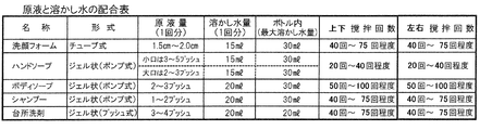
- the method of using the whipping device according to the present invention is the method of using the whipping device that whisks the liquid material by using the whipping device, and the face-washing foam contained in the tube is 1.5 cm to 2.0 cm.
- the storage step for closing the opening / closing portion and the storage step allow the user to hold the whisk in which the liquid material and the coil spring are stored so that the inner space extending vertically is in the vertical direction.
- the whisk containing the liquid material and the coil spring is extended up and down.
- the user holds the coil spring in his / her hand so that the inner space is horizontal, and repeatedly shakes the coil spring 40 to 75 times in the left-right direction, and opens the opening / closing part to open the contents. It is characterized by consisting of a take-out step.
- the facial cleansing foam can be gently penetrated into the skin to form a foam that can efficiently remove stains.
- the method of using the whipping device according to the present invention is the method of using the whipping device that whisks the liquid material by using the whipping device, and pushes the gel-like hand soap stored in the pump-type container 2 to 5 times.
- the storage step for closing the portion and the storage step allow the user to hold the whisk in which the liquid material and the coil spring are stored so that the inner space extending vertically is in the vertical direction.
- a left-right dynamic stirring step in which the user holds the coil spring in the horizontal direction and repeatedly shakes it 20 to 40 times in the left-right direction in which the coil spring can vibrate, and a take-out step in which the opening / closing portion is opened to take out the contents. It is characterized by being composed of.
- the gel-like hand soap stored in the pump-type container can be gently permeated into the skin to form a foam that can efficiently remove dirt.
- the method of using the whipping device according to the present invention is a method of using the whipping device that whisks a liquid material by using the whipping device, and pushes the gel-like body soap stored in the pump-type container two to three times.
- the storage step for closing the portion and the storage step allow the user to hold the whisk in which the liquid material and the coil spring are stored so that the inner space extending vertically is in the vertical direction.
- a left-right dynamic stirring step in which the user holds the coil spring in the horizontal direction and repeatedly shakes it 50 to 100 times in the left-right direction in which the coil spring can vibrate, and a take-out step in which the opening / closing portion is opened to take out the contents. It is characterized by being composed of. As a result, the gel-like body soap stored in the pump-type container can be gently permeated into the skin to form a foam that can efficiently remove dirt.
- the method of using the whipping device according to the present invention is the method of using the whipping device that whisks the liquid material by using the whipping device, and pushes the gel-like shampoo stored in the pump-type container once or twice.
- a liquid material mixed at a ratio of 20 ml of melted water with respect to the product that has a capacity of 30 ml or less of the melted water and the coil spring are stored in the storage portion, and the opening / closing portion is stored.
- the user holds the whisk containing the liquid material and the coil spring in his / her hand so that the inner space extending vertically extends in the vertical direction.
- a vertical stirring step that repeatedly shakes in a vibrable vertical direction 40 to 75 times, and after the vertical movement step, there is an inner space that extends the whisk containing the liquid material and the coil spring up and down.
- a left-right dynamic stirring step in which the user holds the coil spring in the horizontal direction and repeatedly shakes it 40 to 75 times in the left-right direction in which the coil spring can vibrate, and a take-out step in which the opening / closing portion is opened to take out the contents. It is characterized by being composed of.
- the method of using the whisk according to the present invention is the method of using the whisk that whisks the liquid material by using the whisk, and pushes the gel-like kitchen detergent stored in the push-type container three to four times.
- the storage step for closing the portion and the storage step allow the user to hold the whisk in which the liquid material and the coil spring are stored in the hand so that the inner space extending vertically is in the vertical direction.
- the whisk containing the liquid material and the coil spring is extended vertically in the inner space.
- the gel-like kitchen detergent stored in the push-type container can be made into a foam that can efficiently remove stains.
- the method of using the whipping device according to the present invention is a method of using the whipping device that whisks a liquid material by using the whipping device, and manufactures powdered soap that grinds solid face-washing soap into powder using a household grater.
- a storage step in which the liquid material obtained by mixing the powdered soap produced in the powdered soap manufacturing step with 30 ml or less of dissolved water and the coil spring are stored in the storage portion, and the opening / closing portion is closed, and the storage.
- the user holds the whisk containing the liquid material and the coil spring in the vertical direction so that the inner space extending vertically is in the vertical direction, and the coil spring is oriented in the vertical direction in which the coil spring can vibrate.
- the user After the vertical stirring step of repeatedly shaking 40 to 100 times and the vertical movement step, the user so that the inner space extending vertically from the whisk containing the liquid material and the coil spring is in the horizontal direction. It consists of a left-right dynamic stirring step in which the coil spring is repeatedly shaken 40 to 100 times in a horizontal direction in which the coil spring can vibrate, and a take-out step in which the opening / closing portion is opened to take out the contents.
- the solid face-wash soap can be gently permeated into the skin to form a foam that can efficiently remove stains.
- a hand-rubbing step is added in which the user picks up the contents taken out in the take-out step and rubs the hands, so that the moist creamy foam state is changed to a fluffy creamy foam. And. This makes it possible to make a fluffy creamy foam.
- the stirring method of the whipping device is a stirring method of dissolving a powdery body in a liquid by using the whipping device, in which the powdery body, the liquid and the coil spring are stored in the storage portion, and the said.
- the storage step for closing the opening / closing portion and the storage step allow the user to hold the whisk containing the powder, the liquid, and the coil spring so that the inner space extending vertically is vertical. After the vertical stirring step in which the coil spring is repeatedly shaken in a vibrable vertical direction, and after the vertical movement step, a whisk containing the powdery body, the liquid, and the coil spring is extended vertically.
- the user puts the liquid material in the whisk and shakes it by hand to make the coil spring move including vibration and rocking, thereby dispersing the dispersed substance in the liquid. It has the effect that it can be whipped and immediately taken out from the opening / closing part for use.
- the user puts the liquid material in this whisk and shakes it so that the longitudinal direction is vertical and the coil spring vibrates in the longitudinal direction, and the longitudinal direction is horizontal.
- the coil spring move including vibration and swing by two actions, that is, the action of shaking the coil spring so as to vibrate in the direction, it is possible to disperse the material to be dispersed in the liquid and further foam it. Immediately after that, it can be taken out from the opening / closing part and used.
- the pitch of the coil springs By providing the pitch of the coil springs to be sparse and dense, it is easy to maintain vibration and swing by using the coil spring portion as a weight. Further, the portion where the pitch of the coil spring is dense stirs the liquid body, and brings about a shearing effect. Since the winding diameter of the coil is constant, in a posture where the longitudinal direction of the whisk is horizontal, the dense part of the pitch in the center of the coil spring is the content along the inner wall of the whisk. It has the effect of stirring like rubbing.
- FIG. 2 is a diagram of a whisk having a cap that moves up and down with a screw type at the upper opening / closing portion of the second embodiment of the whisk. It is a figure which shows the foam taking-out port provided in the upper opening / closing part of Embodiment 2 of a whisk. It is a figure which shows the state which opened the upper opening and closing part of Embodiment 2 of a whisk. It is a figure of a coil spring 20.
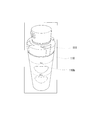
- FIG. 1 is a diagram showing a configuration of a whisk according to the present invention.
- the storage unit 10 is a container that can store a liquid material. Desirably, it is made of a transparent or translucent material such as polyethylene or polypropylene, and the status of separation, precipitation, dispersion, etc. of the contents can be visually confirmed. Further, preferably, the storage portion 10 has a self-supporting shape, and can be placed upright in a refrigerator, for example.
- the size of the storage portion depicted in FIG. 1 can be, for example, a height of 150 mm and a diameter of 60 mm.
- a diameter of 50 mm to 70 mm, a height of 150 mm to 170 mm, and a capacity of about 280 mm to 400 mm are suitable for a person to hold and shake.
- the shape of the storage portion 10 drawn in FIG. 1 is similar to that of a cylinder, but may be another shape. Make the center slightly wider to increase the capacity to store foam. To prevent the whisk from slipping off your hand when you shake it, make the center part easy to grip, for example, a shape that you can easily grip with your fingers. And so on.
- An upper opening / closing portion 11 is provided on the upper portion of the storage portion 10, so that the liquid material can be taken in and out of the storage portion 10.
- the upper opening / closing portion 11 is configured by a screw type cap.
- the upper opening / closing portion 11 is provided with a tube for taking out bubbles, and a cap is further provided at the tip of the tube, and bubbles can be taken in and out by opening and closing the cap. It is desirable that the upper opening / closing portion 11 can be fastened to the storage portion 10 and can maintain the airtightness so that the contents do not spill even when shaken by hand. As long as the airtightness in the tightened state can be maintained, not only the screw type but also other opening / closing parts such as a fitting type can be used.
- both the upper opening / closing portion 11 and the lower opening / closing portion 12 can be molded from a resin such as polyethylene or polypropylene.
- the bubble outlet provided in the upper opening / closing portion can be made into a desired shape such as a star shape in addition to the round hole.
- the coil spring 20 Since the coil spring 20 is placed inside the storage portion 10, it is drawn by a broken line in FIG. The design of the coil spring 20 (dense pitch, wire diameter constituting the coil spring) will be described later with reference to FIG.
- the coil spring 20 is placed in a state where it is not fixed anywhere so that it can move freely inside the storage portion 10. That is, it is possible to freely move including vibration and rocking.
- the surface of the wire constituting the coil spring 20 may have various surfaces and may have irregularities. It is desirable that both ends of the wire constituting the coil spring 20 be rounded so as not to damage the inside of the storage portion 10. For example, pickling can be considered.
- the coil spring 20 is a coil spring having a constant winding diameter. As shown in FIG. 1, the winding diameter is smaller than the horizontal size inside the storage portion 10, and when the user holds and shakes the whisk, the coil spring 20 is used. There is room for space for movement, including vibration and rocking.
- vibration means movement in the direction of expansion and contraction of the coil spring 20
- vibration means movement in the direction perpendicular to the direction of expansion and contraction.
- the length of the coil spring 20 is preferably 50% to 70% of the height inside the housing 20. If it is too short, the stirring efficiency of the entire liquid material will be small. If it is too long, the degree of freedom of movement including vibration and rocking will be narrowed.
- the coil spring 20 swings and vibrates, and exerts a shearing effect on the liquid material. Further, when the surface of the coil spring 20 has various surfaces and has irregularities, the surface shape of the coil spring 20 also exerts a shearing effect on the liquid material. As a result, the liquid material is made finer and more uniform, and
- the shock absorbing materials 31, 32, 33 prevent the inside of the storage portion 10, the inside of the upper opening / closing portion 11, and the inside of the lower opening / closing portion 12 from being damaged by the violent movement of the coil spring 20, and reduce the noise at the time of collision. It is provided for the purpose.
- the shock absorbing material 31 provided on the side of the upper opening / closing portion 11 has a donut shape. This is because a hole is needed in the center to blow bubbles through the tube.
- the shock absorbing materials 31, 32, 33 can also serve as packing. That is, when the upper opening / closing portion 11 and the lower opening / closing portion 12 are tightened, the contents containing the liquid do not leak to the outside.
- One shock absorbing material 31 is provided on the side of the upper opening / closing portion 11, and two shock absorbing materials are provided on the side of the lower opening / closing portion 12. This is because the impact when the coil spring 20 is shaken is that a force that takes gravity into consideration is applied to the lower opening / closing portion 12.
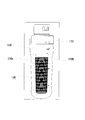
- FIG. 2 is a diagram showing parts constituting the whisk of the present invention.
- the upper part and the lower part of the storage part 10 are threaded, and the upper opening / closing part 11 and the lower opening / closing part 12 are respectively configured as a threaded cap.
- a shock absorbing material 31 is provided inside the upper opening / closing portion 11, and shock absorbing materials 32 and 33 are provided inside the lower opening / closing portion 12.
- the coil spring 20 is a coil spring having a constant winding diameter and sparse and dense in its pitch.
- the upper and lower parts of the coil spring have a dense pitch, and the central part has a sparse pitch. This will be described in detail with reference to FIG.
- FIG. 3 is a diagram illustrating in detail the pitch density of the coil spring and the wire diameter constituting the coil spring.
- stainless steel SUS304 is used as the material.
- the coil spring shown in FIG. 3A has a wire diameter of 1.8 mm and an outer shape (winding diameter) of 40 mm.
- the natural length of the spring (length when placed sideways) is 92.6 mm.
- the length of the tightly wound part with no space at both ends is 10. Millimeters.
- the 3B has a wire diameter of 1.6 mm and an outer diameter (winding diameter) of 40 mm.
- the natural length of the spring (length when placed sideways) is 88.0 mm.
- the length of the tightly wound part with no space at both ends is 11.2 mm.
- the coil spring shown in FIG. 3C has a wire diameter of 1.5 mm and an outer shape (winding diameter) of 40 mm.
- the natural length of the spring (the length when placed sideways) is 86.2 mm.
- the length of the tightly wound part with no space at both ends is 10.5 mm.
- the coil spring shown in FIG. 3D has a wire diameter of 1.4 mm and an outer diameter (winding diameter) of 40 mm.
- the natural length of the spring (length when placed sideways) is 84.8 mm.
- the length of the tightly wound part with no space at both ends is 11.2 mm.
- the wire diameter of the spring can be 1.0 mm to 1.8 mm.
- springs with wire diameters of 1.4 mm to 1.5 mm are suitable.
- springs with a wire diameter of 1.6 mm to 1.8 mm are suitable.
- the natural length of the spring is preferably 80 mm to 95 mm, which corresponds to 50% to 70% in terms of the ratio to the length of the storage portion 10.
- the pitch of the spring is preferably 6 to 8 turns with tight winding at both ends (winding without a gap), and 0.8 mm to 1.0 mm with a clearance between the spring wires at the center.
- both ends are tightly wound and the central part is sparse, the vibration and swing of the coil spring are likely to be sustained for a long time.
- the spring moves up and down (vibrates) in the storage unit.
- the tight winding at both ends of the spring becomes a weight for vertical movement, and when it hits the inside of each of the upper opening / closing portion and the lower opening / closing portion, the spring portion having a large pitch in the center portion of the spring expands and contracts.
- the movement of the coil spring is given a momentum, and it becomes easier for the user to shake the whisk.
- the operation and mechanism of the whisk according to the present invention can be explained from two viewpoints.
- the first is to stir the liquid by vibrating and swinging the coil spring.
- oil lumps, grain lumps, sediment lumps, etc. are sheared to be made smaller and dispersed in a liquid material.
- the action / mechanism of sound overtone resonance scaling resonance
- the opening / closing portion is tightened, and the user holds it in his / her hand and shakes it, an impact is applied to the coil spring. Then, the impact causes the coil spring to vibrate and swing.
- Liquids are not limited to foodstuffs. For example, it can also be used as a building material dispersed (dissolved) in water. It can also be applied to detergents (liquid detergents, powder detergents dissolved in water), hair styling products (liquids for hair styling, etc.), and facial cleansing liquids (cleansing oil, etc.).
- the industrial machine includes both a self-propelled machine such as an industrial vehicle and a fixed machine. Specifically, it includes a hydraulic pump, a boiler, a prime mover, and the like.
- Machine oils include hydraulic oils in hydraulic pumps and lubricating oils in other machines.
- the whisk according to the present invention is useful for homogenizing and filling the oil required for replenishment.
- the whisk of the present invention can be applied to a whisk for cooking, a container for liquids, and a container for seasonings.
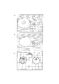
- FIG. 4 is a diagram showing the state of foam after 5 minutes, 15 minutes, and 30 minutes after whipping a commercially available facial cleanser. Put 10 ml of tap water in this whisk, take out the facial cleanser about 1 cm from the tube, attach it to the coil spring, drop the spring into the storage part, and close the upper opening and closing part. After that, the user holds the whisk in his hand and shakes it up and down 50 times. After that, FIG. 4 (a) shows a state in which the formed bubbles are taken out and 5 minutes have passed. FIG. 4 (b) shows the state after 15 minutes. FIG. 4 (c) shows the state after 30 minutes. It can be seen that even after 30 minutes have passed, the state of highly viscous foam is maintained.
- ⁇ Bubbling facial cleanser Commercially available facial cleansers sold in tubes are usually used by stretching them from the palm of your hand, applying them to your face, and then flushing them with water. In that case, the amount used at one time is about 2 cm in the length taken out from the tube.
- the whisk of the present invention it is possible to sufficiently wash the face by taking out the facial cleanser about 1 cm from the tube, using 10 ml of water, and using the whisk. That is, it is possible to wash the face using only half the amount of the face wash, which also saves money.
- it since it is finely sheared with a whisk, it can be expected to have the effect of removing dirt from the back of the skin.
- FIG. 5 is a diagram showing a configuration of a whisk according to the second embodiment of the present invention.
- the storage unit 110 is a container that can store a liquid material. Desirably, it is made of a transparent or translucent material such as polyethylene or polypropylene, and the status of separation, precipitation, dispersion, etc. of the contents can be visually confirmed. Further, preferably, the storage unit 110 has a self-supporting shape and can be placed upright in a refrigerator, for example. In the one drawn in FIG.
- the bottom is rounded, but it is desirable to have a comfortable shape, for example, a shape in which the bottom is slightly widened.
- the size of the storage portion depicted in FIG. 5 can be, for example, 130 mm to 180 mm in height and 50 mm to 70 mm in diameter. Desirably, a diameter of 50 mm to 70 mm, a height of 150 mm to 170 mm, and a capacity of about 280 mm to 400 mm are suitable for a person to hold and shake.
- the shape of the storage portion 110 drawn in FIG. 5 is similar to that of a cylinder, but may be another shape. The central part can also be made slightly wider to increase the capacity to store the foam.
- the storage portion 110 is not only held so as to be up and down in the longitudinal direction, but also held horizontally so that the coil spring 120 moves so as to vibrate. It is desirable that the inner wall of the portion 110 has a structure and a shape so that the coil spring 120 can slide and the liquid body as the content can be sufficiently agitated. To prevent the whisk from slipping off your hand when you shake it, make the center part easy to grip, for example, a shape that you can easily grip with your fingers. And so on.
- FIG. 6 is a diagram showing a foam take-out port 111c provided in the upper opening / closing portion 111 of the second embodiment of the whisk.
- the upper opening / closing portion 111 is provided with a foam outlet 111c for taking out bubbles, and the user puts a finger on the knobs 111a and 111b shown in FIGS. 6A and 6B and turns the foam outlet 111c.
- FIG. 7 is a diagram showing a state in which the upper opening / closing portion 111 of the second embodiment of the whisk is opened.
- the liquid material can be stored in the storage portion 110 in a sealed state.
- a screw is cut inside the upper opening / closing part 111, and the opening / closing can be realized by the screw cut at the upper part of the storage part 110.
- the upper opening / closing portion 111 is fastened to the storage portion 110, it is possible to maintain the hermeticity so that the contents do not spill even if the upper opening / closing portion 111 is shaken by hand.
- not only the screw type but also other opening / closing parts such as a fitting type can be used. As depicted in FIG.
- the coil spring 120 is placed in the storage portion 110 in a freely movable state.
- the upper opening / closing portion 111 can be molded from a resin such as polyethylene or polypropylene.
- the bubble outlet provided in the upper opening / closing portion can be made into a desired shape such as a star shape in addition to the round hole.
- FIG. 8 is a diagram depicting the coil spring 120.
- the coil spring 120 is placed inside the storage portion 110.
- the coil spring 120 has a portion having a dense pitch in the central portion, and the pitch is sparse at both ends (a portion other than the central portion).
- the design (sparse and dense pitch, wire diameter constituting the coil spring) will be described later with reference to FIG.
- the coil spring 120 is placed in a state where it is not fixed anywhere so that it can move freely inside the storage portion 110. That is, it is possible to freely move including vibration and rocking.
- As the material of the coil spring 120 for example, iron (steel), stainless steel, titanium, titanium alloy, aluminum, plastic or the like can be used.
- the surface of the wire constituting the coil spring 120 may have various surfaces and may have irregularities. It is desirable that both ends of the wire constituting the coil spring 120 are rounded so as not to damage the inside of the storage portion 110. For example, pickling can be considered.
- the coil spring 120 is a coil spring having a constant winding diameter. As shown in FIGS. 5 and 7, the winding diameter is smaller than the horizontal size inside the storage portion 110, and the coil spring is used when the user holds and shakes the whisk.
- the 120 is designed to have spatial room for movement, including vibration and rocking.
- vibration refers to movement in the direction of expansion and contraction of the coil spring 120
- vibration refers to movement in the direction perpendicular to the direction of expansion and contraction.
- the length of the coil spring 120 is preferably 60% to 80% of the height inside the housing 110. If it is too short, the stirring efficiency of the entire liquid material will be small. If it is too long, the degree of freedom of movement including vibration and rocking will be narrowed.
- the coil spring 120 swings and vibrates, and exerts a shearing effect on the liquid material. Further, when the surface of the coil spring 120 has various surfaces and has irregularities, the surface shape of the coil spring 120 also exerts a shearing effect on the liquid material. As a result, the liquid material is made finer and more uniform, and dispersion is promoted.
- Embodiment 3 A cap provided with a cap that fits into the receiving portion >> 9, 10, and 11 are views of the third embodiment of the whisk as viewed from the outside.
- the storage portion 110 is provided with grip portions 110b and 110c. It has a shape that is easy for the user to grasp and a shape that can be touched by a finger.
- FIG. 12 shows a lid portion 112a and a receiving portion 112b provided in the upper opening / closing portion of the third embodiment of the whisk. In FIG. 112 (a), the lid portion 112a is fitted in the receiving portion 112b and is sealed so that the contents do not come out.
- FIG. 12B shows a state in which the lid portion 112a is open and the contents can be taken out from the foam extraction port 112c.
- FIG. 12 (b) a protrusion is provided on the back side of the lid portion 112a to close the hole of the foam take-out port 112c, and when the lid portion 112a is closed, the protrusion takes out the foam. Close the mouth 112c.
- FIG. 13 shows a state in which the upper opening / closing portion 112 is removed from the storage portion 110. The sealed state is maintained by the screws cut on the inside of the upper opening / closing portion 112 and the outside of the storage portion 110.
- FIG. 13B shows a state in which the coil spring 120 is housed.
- FIG. 14 is a diagram showing parts constituting the third embodiment of the whisk.
- the upper part of the storage part 110 is threaded, and the upper opening / closing part 112 is configured as a threaded cap.
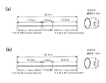
- FIG. 15 is a diagram illustrating the density of the pitch of the coil spring and the wire diameter constituting the coil spring.
- the material is stainless steel SUS304.
- As for the wire diameter we tried 1.2 mm, 1.3 mm, 1.4 mm, 1.5 mm, and 1.6 mm, and found that the effect was seen. Here, in particular, detailed figures are given for those of 1.4 mm and 1.3 mm.
- the coil spring shown in FIG. 15A has a wire diameter of 1.4 mm and an outer diameter (winding diameter) of 36 mm.
- the natural length of the spring (the length when placed sideways) is 128.4 mm. Both ends are 0.8 mm in length and the length of the tightly wound part is 14 mm.
- the coil spring shown in FIG. 15B has a wire diameter of 1.3 mm and an outer diameter (winding diameter) of 36 mm.
- the natural length of the spring (length when placed sideways) is 130.6 mm.
- Both ends are 0.8 mm in length and the length of the tightly wound part is 13 mm.
- Regarding the length of the coil (natural length) it was found that 60% to 80% of the height inside the storage portion 10 is desirable.
- the winding diameter of the coil spring is preferably 55% to 85% of the inner diameter of the housing.
- FIG. 16 is a composition table of undiluted solution and dissolved water. It is a table of the contents of the text in the problem-solving means.
- FIG. 17 is a diagram of a free-running spring foaming test.
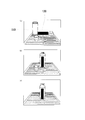
- FIG. 17A shows a state in which a teaspoon of soap powder, 20 ml of dissolved water, and a whisk according to the present invention (having a coil spring 120 having a dense center and sparse ends) are prepared.
- FIG. 17B shows a state in which the coil spring 120, a teaspoon of soap powder, and 20 ml of melted water are put into the storage portion 110 of the whisk, and the opening / closing portion 12 is closed.
- FIG. 17C shows a state of stirring 100 times.
- FIG. 18 is a diagram of a free-running spring foaming test.
- FIG. 18D shows a state of stirring 200 times.
- FIG. 18 (e) shows a state of stirring 300 times.
- FIG. 18 (f) shows a state in which the contents after stirring 300 times were taken out and their dimensions were measured.
- the horizontal length of the bottom is 11.0 cm
- the vertical length of the bottom is 11.0 cm
- the height of the foam is 4.0 cm.
- FIG. 19 is a diagram of a free-running spring foaming (moist to fluffy) test.
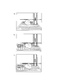
- FIG. 19A shows a state in which a teaspoon of soap powder, 20 ml of dissolved water, and a whisk according to the present invention (having a coil spring 20 having a dense center and sparse ends) are prepared.
- FIG. 19B shows how the contents (moist creamy foam) after stirring 300 times were taken out and their dimensions were measured.
- FIG. 19C shows a foam (fluffy creamy foam) after taking out the foam produced by stirring 300 times using a whisk and rubbing the hands in the open air for 60 seconds.
- the horizontal length of the bottom is 8.0 cm
- the vertical length of the bottom is 8.0 cm
- the height of the foam is 6.5 cm.
- FIG. 20 is a diagram of a free-running spring foaming (fluffy demonstration) test.
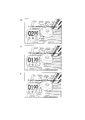
- FIG. 20A shows a foam (fluffy creamy foam) obtained by adding 1 teaspoon of soap powder and 20 ml of dissolved water and stirring the foam 300 times in the open air for 60 seconds.
- FIG. 20 (b) shows a leveled state of fluffy creamy foam, that is, a bottom width of 10.0 cm, a bottom length of 10.0 cm, and a foam height of 3.0 cm. A round ball is placed and the sinking measurement is started for 3 minutes.
- FIG. 20 (c) shows a state after 30 seconds have passed. The 10-yen coin has sunk 1.0 centimeters.
- FIG. 21 is a diagram of a free-running spring foaming (fluffy demonstration) test.
- FIG. 21D shows a state after 1 minute and 00 seconds have elapsed.
- the 10-yen coin has sunk 2.0 centimeters.
- FIG. 21 (e) shows a state after 1 minute and 30 seconds have elapsed.
- the 10-yen coin has sunk 2.3 centimeters.
- FIG. 21 (f) shows a state after lapse of 2 minutes and 00 seconds.
- the 10-yen coin has sunk 2.6 centimeters.
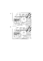
- FIG. 22 is a diagram of a free-running spring foaming (fluffy demonstration) test.
- FIG. 22 (g) shows a state after 2 minutes and 30 seconds have elapsed.
- the 10-yen coin has sunk 2.6 centimeters.
- FIG. 22 (h) shows the state after the lapse of 3 minutes and 00 seconds.
- the 10-yen coin has sunk 2.6 centimeters.
- FIG. 23 is a diagram of a free-running spring foaming (10-yen coin surface cleaning effect) test.
- the 10-yen coin was left for 20 hours after the settlement measurement of the 10-yen coin was performed, the surface of the 10-yen coin after 20 hours was washed, and the 10-yen coin was shining and glossy.
- the subsidence measurement experiment for 3 minutes was performed without rubbing.
- a photograph was taken with a 10-yen coin (copper coin) that had the same degree of dirt.
- FIG. 23 (a) is a photograph in which a 10-yen coin taken out from a bubble immediately after a settlement measurement experiment and a 10-yen coin to be compared are arranged side by side. The right is the 10-yen coin used for settlement measurement, and the left is the 10-yen coin to be compared.
- FIG. 23 (b) shows a state in which the trace of the subsidence of the bubbles disappears after another 30 minutes have passed.
- FIG. 23 (c) is an enlarged photograph.
- FIG. 24 is a diagram showing a method for producing the powdered soap used in the experiments shown in FIGS. 17 to 23.
- FIG. 24A shows a solid soap for face washing, which is a raw material.
- FIG. 24 (b) shows how to grind solid soap with a household grater.
- FIG. 25 is a diagram of a test of a conventional product (fluffy rich) as a comparative example. This whisk is a whisk that can be purchased for 100 yen. A disk-shaped stirring plate with a large number of holes can be moved up and down and rotated in the horizontal direction by operating from above.
- FIG. 25 (a) shows a state in which a teaspoon of soap powder, 20 ml of dissolved water, and a conventional whisk are prepared.
- FIG. 25B shows a state in which a teaspoon of soap powder and 20 ml of dissolved water are placed in a conventional whisk, and a disk-shaped stirring plate and an upper lid are set.
- FIG. 25 (c) shows a state in which whipping is stirred 100 times.
- FIG. 26 is a diagram of a test of a conventional product (fluffy rich) as a comparative example.
- FIG. 26D shows a state in which whipping is stirred 200 times.
- FIG. 26 (e) shows a state in which whipping is stirred 300 times.
- FIG. 26 (f) shows a state in which the contents after stirring 300 times are taken out and their dimensions are measured.
- the horizontal length of the bottom is 13.0 cm
- the vertical length of the bottom is 13.0 cm
- the height of the foam is 3.0 cm. It can be seen that the foam has a weak viscosity (stickiness) as compared with the foam produced by using the whisk according to the present invention. Therefore, it can be said that the viscosity (stickiness) of the foam produced by the whisk according to the present invention is strong.
- FIG. 27 is a perspective view showing the silencer 130.
- the silencer 130 can be made of soft plastic and can be made by preparing and molding the necessary molds.
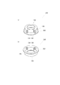
- the silencer 130 has a coil spring contact portion 132 that abuts and supports 80% of the planar spread formed by one roll of the end of the coil spring, and a coil spring.
- Two vertical walls provided at the limit where the coil spring of the coil spring contact portion 132 abuts, which is perpendicular to the contact portion 132 and also to the coil constituting the coil spring.
- a cylindrical wall extending vertically to a certain first vertical wall 134, a second vertical wall 136, and a coil spring contact portion 132 on the opposite side of the coil spring, and the outer diameter of the coil spring is set to the inner diameter. It has a cylindrical wall portion 138 and the like.
- the first vertical wall 134 and the second vertical wall 136 have two holes 142, 144, 146, and 148 through which the coils constituting the coil spring can pass, respectively, in the extending direction of the coil spring. It is installed side by side.
- FIG. 28 is a diagram showing how the silencer 130 is attached to the freely operating coil spring.
- 80% of the end portion of the coil spring is in contact with the coil spring contact portion 132.
- the end of the coil forming the coil spring turns the coil through the hole 142 provided in the first vertical wall 134 so as to reach the other side of the first vertical wall 134.
- turning the coil means turning the coil with its central axis as the axis of rotation when it is viewed as a cylinder.
- the tip of the coil moves along the inner wall of the cylindrical wall portion 138.
- the tip of the coil approaches the hole 146 from the other side of the second vertical wall 136.
- FIG. 28 (b) depicts this state.
- the tip of the coil reaches the position of the hole 148 provided in the second vertical wall 136.
- the silencer 130 is mounted on the coil spring. Since two turns of the coil pass through the silencer 130 and pass through the four holes, the silencer 130 and the coil spring are combined with a strength that can withstand the vibration and swing of the coil spring. That is, the coil spring and the silencer 130 are attached in a removable state.
- FIG. 29 is a perspective view showing a silencer having a widened brim (spring fixture) 230.
- the outer diameter of the portion of the coil spring contact portion 130 and the outer diameter of the portion corresponding to the back side thereof are about the same.
- a silencer with a flange (spring fixing tool) 230 is provided with a flange 232 on the back side of the coil spring contact portion 132 to make it wider.
- the collar 232 is a disk (or an annular member) parallel to the coil spring contact portion 132 on the side opposite to the coil spring contact portion 132 of the cylindrical wall portion and extends outward. be.
- the outer diameter of the collar 232 is larger than the inner diameter of the opening of the upper storage portion and is the same as the outer diameter of the opening of the upper storage portion.
- FIG. 30 is a diagram showing how the spring is fixed to the upper part of the whisk using the spring fixture 230.
- a silencer with a flange (spring fixture) 230 is attached to the coil spring 220 in the same manner as in FIG. 28. Then, the coil spring 220 is inserted into the storage portion 210. At this time, since the outer diameter of the collar 232 is larger than the inner diameter of the opening of the upper storage portion, the collar 232 is caught by the opening and stops.
- the spring fixture 230 is fixed and the coil spring 220 is fixed. Both the spring fixture 230 and the silencer 130 are removable, and the user who purchased the whisk can provide the spring fixture 230 and the silencer 130 so that they can be attached and detached.
- the user can use the whisk in various variations. For example, by attaching two silencers 130 to both ends of the coil spring, noise can be reduced. If sufficient stirring force can be obtained with the coil spring fixed to the upper part, remove the silencer 130 on one side of the coil spring, replace it with the spring fixture 230, and use it with the coil spring suspended on the upper part. It is possible to do. When fixing the coil spring to the upper part, it is easy to take out the coil spring after use. When the coil spring is used as a freely movable one, it takes time to take out the coil spring, but it is expected that the stirring force will be large.
- Hand washing is an important skill in these days when there are many infectious diseases.
- the reason why it is better to lather and wash soaps is that it is possible to remove stains efficiently and with low irritation by lathering well. It is important to use soaps and cleansers that are gentle on the skin. It is said that it is important to lather well, do not rub the skin too much, and wash it off thoroughly.
- Surfactant molecules are involved in removing stains, and have a hydrophilic group that is easily compatible with water and a lipophilic group that is easily compatible with oil.
- the mechanism of cleaning with a surfactant is to wrap sebum and dirt with the lipophilic group toward the dirt and the hydrophilic group toward the water, and penetrate between the skin and the dirt to remove the dirt.
- the surfactant has a foaming action, and it can be expected to have the effect of raising stains by foaming and efficiently removing stains without rubbing the skin too much.
- the cleaning agent spreads to details such as wrinkles on the skin, and secondly, by making dirt stand out, dirt can be removed efficiently with less friction, third.
- foaming soap and detergent foaming is done by the three-way relationship of undiluted solution, dissolved water and air.
- a fluffy creamy foam is formed by mixing the undiluted solution and dissolved water in the air and whipping.
- the foam formed in the whisk 400 ml becomes moist creamy foam.
- the moist creamy foam comes out of the bottle into the atmosphere, it turns into a fluffy creamy foam.
- Liquids are not limited to facial cleansers, detergents, shampoos, etc.
- it can also be used as a building material dispersed (dissolved) in water. It can also be applied to hair styling products (such as hair styling liquids) and cleansing oils.
- the industrial machine includes both a self-propelled machine such as an industrial vehicle and a fixed machine. Specifically, it includes a hydraulic pump, a boiler, a prime mover, and the like.
- Machine oils include hydraulic oils in hydraulic pumps and lubricating oils in other machines.
- the whisk according to the present invention is useful for homogenizing and filling the oil required for replenishment.
- the whisk of the present invention can be applied to a whisk for cooking and a seasoning container.
- whisk or container for dressing-type seasonings that are used by dispersing the oil phase in the aqueous phase. It can also be used as a whisk or container used for dispersing (dissolving) flour such as cake flour in water. It can be used as a whisk to whisk milk. Furthermore, it can be used as a whisk or a container when powder or oil is dispersed in water and used, such as construction materials, detergents, hair styling products, facial cleansers, facial cleansers, and body soaps, as well as foodstuffs. Furthermore, it can also be applied to stirring industrial machine oils.
Landscapes
- Chemical & Material Sciences (AREA)
- Chemical Kinetics & Catalysis (AREA)
- Engineering & Computer Science (AREA)
- General Engineering & Computer Science (AREA)
- Mechanical Engineering (AREA)
- Dispersion Chemistry (AREA)
- Food Science & Technology (AREA)
- Food-Manufacturing Devices (AREA)
Abstract
Priority Applications (5)
| Application Number | Priority Date | Filing Date | Title |
|---|---|---|---|
| JP2021542471A JP6964923B1 (ja) | 2020-05-11 | 2021-05-10 | 巻き径が一定でありピッチに疎密を有し容器内を自由に移動可能なコイルばねを有する泡立て器及び使用方法 |
| EP21804033.5A EP4074231A4 (fr) | 2020-05-11 | 2021-05-10 | Outil de moussage, comprenant un ressort hélicoïdal avec un diamètre d'enroulement constant et un pas variable pouvant se déplacer librement à l'intérieur du récipient, et procédé d'utilisation de celui-ci |
| KR1020227043179A KR20230008847A (ko) | 2020-05-11 | 2021-05-10 | 권취 직경이 일정하고 피치에 소밀을 갖고 용기 내를 자유롭게 이동 가능한 코일 스프링을 갖는 거품기 및 사용방법 |
| CN202180015978.3A CN115151170A (zh) | 2020-05-11 | 2021-05-10 | 具有卷径恒定、间距有疏密并且能够在容器内自由移动的螺旋弹簧的起泡器和使用方法 |
| US17/904,323 US20230058664A1 (en) | 2020-05-11 | 2021-05-10 | Device for mixing, whipping, and frothing materials with coil spring with constant winding diameter, sparse and dense pitch, and freely movable in bottle, and method of using the same |
Applications Claiming Priority (4)
| Application Number | Priority Date | Filing Date | Title |
|---|---|---|---|
| JP2020083280 | 2020-05-11 | ||
| JP2020-083280 | 2020-05-11 | ||
| JP2020-198483 | 2020-11-30 | ||
| JP2020198483 | 2020-11-30 |
Publications (1)
| Publication Number | Publication Date |
|---|---|
| WO2021230196A1 true WO2021230196A1 (fr) | 2021-11-18 |
Family
ID=78524383
Family Applications (1)
| Application Number | Title | Priority Date | Filing Date |
|---|---|---|---|
| PCT/JP2021/017687 Ceased WO2021230196A1 (fr) | 2020-05-11 | 2021-05-10 | Outil de moussage, comprenant un ressort hélicoïdal avec un diamètre d'enroulement constant et un pas variable pouvant se déplacer librement à l'intérieur du récipient, et procédé d'utilisation de celui-ci |
Country Status (1)
| Country | Link |
|---|---|
| WO (1) | WO2021230196A1 (fr) |
Citations (14)
| Publication number | Priority date | Publication date | Assignee | Title |
|---|---|---|---|---|
| US3136532A (en) * | 1961-09-20 | 1964-06-09 | George A Rudnick | Liquid blending appliance |
| JP3073290U (ja) * | 2000-05-17 | 2000-11-14 | 三菱製鋼株式会社 | コイルばね用消音スパイラルチューブ |
| JP2002178737A (ja) * | 2000-12-14 | 2002-06-26 | Yokohama Rubber Co Ltd:The | 自動車用緩衝装置 |
| JP2002369665A (ja) | 2001-06-15 | 2002-12-24 | Kikkoman Corp | 包装容器入り食用油脂類分離型ごま粒子含有液状調味料の製造方法 |
| JP2011109973A (ja) | 2009-11-27 | 2011-06-09 | Q P Corp | 容器入り分離液状調味料 |
| JP4724175B2 (ja) | 2004-03-19 | 2011-07-13 | グリーン テクノロジーズ サルル | 混練を改善するためのオゾンの使用 |
| JP2013111064A (ja) | 2011-11-30 | 2013-06-10 | Q P Corp | 容器入り大根おろし含有液状調味料 |
| JP2014124123A (ja) | 2012-12-26 | 2014-07-07 | Ajinomoto Co Inc | 容器詰め液状調味料とこれを用いた食肉調理食品の製造方法 |
| US20150290605A1 (en) | 2014-04-09 | 2015-10-15 | Anastasia B. Dayton | Agitation assembly |
| JP2015212601A (ja) | 2014-05-07 | 2015-11-26 | Cpmホールディング株式会社 | ヒートポンプシステムにおける流体撹拌装置 |
| JP2017019562A (ja) | 2015-07-10 | 2017-01-26 | キユーピー株式会社 | 液状調味料容器及び容器詰液状調味料 |
| JP2017212889A (ja) | 2016-05-30 | 2017-12-07 | 鈴茂器工株式会社 | 食材攪拌装置および食材攪拌方法 |
| US20190299175A1 (en) * | 2018-03-30 | 2019-10-03 | Runway Blue, Llc | Agitators |
| JP3225011U (ja) * | 2019-08-28 | 2020-02-06 | Ddマシン西日本株式会社 | 泡立て器、調味料泡立て方法、食材泡立て方法、飲料泡立て方法、洗顔料泡立て方法、整髪料泡立て方法、洗剤泡立て方法、建設資材泡立て方法、産業機械油類の撹拌方法 |
-
2021
- 2021-05-10 WO PCT/JP2021/017687 patent/WO2021230196A1/fr not_active Ceased
Patent Citations (14)
| Publication number | Priority date | Publication date | Assignee | Title |
|---|---|---|---|---|
| US3136532A (en) * | 1961-09-20 | 1964-06-09 | George A Rudnick | Liquid blending appliance |
| JP3073290U (ja) * | 2000-05-17 | 2000-11-14 | 三菱製鋼株式会社 | コイルばね用消音スパイラルチューブ |
| JP2002178737A (ja) * | 2000-12-14 | 2002-06-26 | Yokohama Rubber Co Ltd:The | 自動車用緩衝装置 |
| JP2002369665A (ja) | 2001-06-15 | 2002-12-24 | Kikkoman Corp | 包装容器入り食用油脂類分離型ごま粒子含有液状調味料の製造方法 |
| JP4724175B2 (ja) | 2004-03-19 | 2011-07-13 | グリーン テクノロジーズ サルル | 混練を改善するためのオゾンの使用 |
| JP2011109973A (ja) | 2009-11-27 | 2011-06-09 | Q P Corp | 容器入り分離液状調味料 |
| JP2013111064A (ja) | 2011-11-30 | 2013-06-10 | Q P Corp | 容器入り大根おろし含有液状調味料 |
| JP2014124123A (ja) | 2012-12-26 | 2014-07-07 | Ajinomoto Co Inc | 容器詰め液状調味料とこれを用いた食肉調理食品の製造方法 |
| US20150290605A1 (en) | 2014-04-09 | 2015-10-15 | Anastasia B. Dayton | Agitation assembly |
| JP2015212601A (ja) | 2014-05-07 | 2015-11-26 | Cpmホールディング株式会社 | ヒートポンプシステムにおける流体撹拌装置 |
| JP2017019562A (ja) | 2015-07-10 | 2017-01-26 | キユーピー株式会社 | 液状調味料容器及び容器詰液状調味料 |
| JP2017212889A (ja) | 2016-05-30 | 2017-12-07 | 鈴茂器工株式会社 | 食材攪拌装置および食材攪拌方法 |
| US20190299175A1 (en) * | 2018-03-30 | 2019-10-03 | Runway Blue, Llc | Agitators |
| JP3225011U (ja) * | 2019-08-28 | 2020-02-06 | Ddマシン西日本株式会社 | 泡立て器、調味料泡立て方法、食材泡立て方法、飲料泡立て方法、洗顔料泡立て方法、整髪料泡立て方法、洗剤泡立て方法、建設資材泡立て方法、産業機械油類の撹拌方法 |
Similar Documents
| Publication | Publication Date | Title |
|---|---|---|
| US8926165B2 (en) | Agitation mixing apparatus | |
| JP3225011U (ja) | 泡立て器、調味料泡立て方法、食材泡立て方法、飲料泡立て方法、洗顔料泡立て方法、整髪料泡立て方法、洗剤泡立て方法、建設資材泡立て方法、産業機械油類の撹拌方法 | |
| US4607756A (en) | Container | |
| JP5676463B2 (ja) | 化粧システム用の包装システム | |
| US10730663B2 (en) | Mixer for a sports and water bottle | |
| JP5965064B2 (ja) | 泡生成ディスペンサ | |
| MXPA06012925A (es) | Limpiador espumado con particulas suspendidas, un metodo para producir el mismo, y un distribuidor del mismo. | |
| JP6960188B1 (ja) | 巻き径が一定でありピッチに疎密を有し容器内を自由に移動可能なコイルばねを用いる泡立て方法 | |
| US20190350246A1 (en) | Kinetic fruit and veggie turbo wash | |
| RU2501598C1 (ru) | Способ одновременной ультразвуковой кавитационной обработки объемов жидких сред | |
| JP2015204986A (ja) | 泡立器 | |
| JP6964923B1 (ja) | 巻き径が一定でありピッチに疎密を有し容器内を自由に移動可能なコイルばねを有する泡立て器及び使用方法 | |
| WO2021230196A1 (fr) | Outil de moussage, comprenant un ressort hélicoïdal avec un diamètre d'enroulement constant et un pas variable pouvant se déplacer librement à l'intérieur du récipient, et procédé d'utilisation de celui-ci | |
| JP6357286B1 (ja) | 液状体の撹拌器 | |
| US20120067749A1 (en) | Container | |
| JP6703246B1 (ja) | 泡立て器 | |
| WO2019043976A1 (fr) | Générateur d'ultrasons, dispositif de lavage et appareil d'extraction | |
| JPWO2020250406A1 (ja) | 泡立て器、調味料泡立て方法、食材泡立て方法、飲料泡立て方法、洗顔料泡立て方法、整髪料泡立て方法、洗剤泡立て方法、建設資材泡立て方法、産業機械油類の撹拌方法 | |
| JP6629687B2 (ja) | 調理用攪拌器 | |
| US5286106A (en) | Soap creamer and dispenser | |
| US20240285115A1 (en) | Kava Batch Beverage Brewing Method and Apparatus | |
| JP2025017789A (ja) | 攪拌装置 | |
| US20060079416A1 (en) | System and method for a mesh cleansing device | |
| JP6345477B2 (ja) | 泡立器 | |
| JP7488434B1 (ja) | 攪拌装置及びそれに用いる自由ばね部 |
Legal Events
| Date | Code | Title | Description |
|---|---|---|---|
| ENP | Entry into the national phase |
Ref document number: 2021542471 Country of ref document: JP Kind code of ref document: A |
|
| 121 | Ep: the epo has been informed by wipo that ep was designated in this application |
Ref document number: 21804033 Country of ref document: EP Kind code of ref document: A1 |
|
| ENP | Entry into the national phase |
Ref document number: 2021804033 Country of ref document: EP Effective date: 20220712 |
|
| ENP | Entry into the national phase |
Ref document number: 20227043179 Country of ref document: KR Kind code of ref document: A |
|
| NENP | Non-entry into the national phase |
Ref country code: DE |