WO2021235331A1 - Robot suiveur - Google Patents
Robot suiveur Download PDFInfo
- Publication number
- WO2021235331A1 WO2021235331A1 PCT/JP2021/018348 JP2021018348W WO2021235331A1 WO 2021235331 A1 WO2021235331 A1 WO 2021235331A1 JP 2021018348 W JP2021018348 W JP 2021018348W WO 2021235331 A1 WO2021235331 A1 WO 2021235331A1
- Authority
- WO
- WIPO (PCT)
- Prior art keywords
- robot
- target
- arm
- follow
- feature amount
- Prior art date
- Legal status (The legal status is an assumption and is not a legal conclusion. Google has not performed a legal analysis and makes no representation as to the accuracy of the status listed.)
- Ceased
Links
Images


Classifications
-
- B—PERFORMING OPERATIONS; TRANSPORTING
- B25—HAND TOOLS; PORTABLE POWER-DRIVEN TOOLS; MANIPULATORS
- B25J—MANIPULATORS; CHAMBERS PROVIDED WITH MANIPULATION DEVICES
- B25J9/00—Program-controlled manipulators
- B25J9/0093—Program-controlled manipulators co-operating with conveyor means
-
- B—PERFORMING OPERATIONS; TRANSPORTING
- B25—HAND TOOLS; PORTABLE POWER-DRIVEN TOOLS; MANIPULATORS
- B25J—MANIPULATORS; CHAMBERS PROVIDED WITH MANIPULATION DEVICES
- B25J9/00—Program-controlled manipulators
- B25J9/16—Program controls
- B25J9/1694—Program controls characterised by use of sensors other than normal servo-feedback from position, speed or acceleration sensors, perception control, multi-sensor controlled systems, sensor fusion
- B25J9/1697—Vision controlled systems
-
- B—PERFORMING OPERATIONS; TRANSPORTING
- B25—HAND TOOLS; PORTABLE POWER-DRIVEN TOOLS; MANIPULATORS
- B25J—MANIPULATORS; CHAMBERS PROVIDED WITH MANIPULATION DEVICES
- B25J13/00—Controls for manipulators
- B25J13/08—Controls for manipulators by means of sensing devices, e.g. viewing or touching devices
-
- B—PERFORMING OPERATIONS; TRANSPORTING
- B25—HAND TOOLS; PORTABLE POWER-DRIVEN TOOLS; MANIPULATORS
- B25J—MANIPULATORS; CHAMBERS PROVIDED WITH MANIPULATION DEVICES
- B25J9/00—Program-controlled manipulators
- B25J9/16—Program controls
- B25J9/1679—Program controls characterised by the tasks executed
- B25J9/1684—Tracking a line or surface by means of sensors
-
- G—PHYSICS
- G05—CONTROLLING; REGULATING
- G05B—CONTROL OR REGULATING SYSTEMS IN GENERAL; FUNCTIONAL ELEMENTS OF SUCH SYSTEMS; MONITORING OR TESTING ARRANGEMENTS FOR SUCH SYSTEMS OR ELEMENTS
- G05B2219/00—Program-control systems
- G05B2219/30—Nc systems
- G05B2219/39—Robotics, robotics to robotics hand
- G05B2219/39102—Manipulator cooperating with conveyor
-
- G—PHYSICS
- G05—CONTROLLING; REGULATING
- G05B—CONTROL OR REGULATING SYSTEMS IN GENERAL; FUNCTIONAL ELEMENTS OF SUCH SYSTEMS; MONITORING OR TESTING ARRANGEMENTS FOR SUCH SYSTEMS OR ELEMENTS
- G05B2219/00—Program-control systems
- G05B2219/30—Nc systems
- G05B2219/39—Robotics, robotics to robotics hand
- G05B2219/39529—Force, torque sensor in wrist, end effector
-
- G—PHYSICS
- G05—CONTROLLING; REGULATING
- G05B—CONTROL OR REGULATING SYSTEMS IN GENERAL; FUNCTIONAL ELEMENTS OF SUCH SYSTEMS; MONITORING OR TESTING ARRANGEMENTS FOR SUCH SYSTEMS OR ELEMENTS
- G05B2219/00—Program-control systems
- G05B2219/30—Nc systems
- G05B2219/40—Robotics, robotics mapping to robotics vision
- G05B2219/40613—Camera, laser scanner on end effector, hand eye manipulator, local
Definitions
- This disclosure relates to a follow-up robot.
- a production line including a robot, a transport device for transporting an article, a rail provided along the transport device, and a moving device for moving the robot along the rail
- Patent Document a production line including a robot, a transport device for transporting an article, a rail provided along the transport device, and a moving device for moving the robot along the rail.
- a robot performs defect inspection and polishing of an article while the article is being conveyed by a conveying device.
- the moving device moves the robot along the rail at the same speed as the transporting speed of the article by the transporting device.
- Patent Document 2 a technique for accurately adjusting the position and posture of the tip of the robot to a target position that does not move is known (see, for example, Patent Document 2).
- the production line only performs defect inspection and polishing.
- defect inspection and polishing For example, when the work in which the robot and the article may interfere with each other is performed, it is necessary to take measures to prevent damage to the robot, the transport device, the article, and the like.
- it is difficult to prevent the above-mentioned damage because the article moving by the transport device may behave unpredictably such as vibration. Therefore, it is desired that the robot tool can accurately follow the article.
- One aspect of the present disclosure is at least one of the following objects as target data for making the movable arm, at least one visual sensor provided on the arm, and the visual sensor provided on the arm follow the following object.
- a feature amount storage unit that stores a first feature amount related to a position and a posture, and a feature that detects a second feature amount related to the current at least position and posture of the follow-up object by using an image obtained by the visual sensor.
- An amount detecting means and a movement amount calculating means that calculates a movement command of the arm based on the difference between the second feature amount and the first feature amount and adjusts the movement command at least by using feed forward control.
- the movement command means for moving the arm based on the movement command, the signal acquired at the start of the specific operation of the tracking target, and the arm for following the trajectory of the tracking target in the specific operation.
- the movement command means is provided with an input value storage unit that stores the input value of the feed forward control in association with the input value, and the movement command means while the movement amount calculation means and the movement command means make the visual sensor follow the follow target.
- the calculation and the movement of the arm based on the movement command are repeated, and the movement command is the at least position and posture of the tracking object as the second feature quantity and at least the position of the tracking target as the first feature quantity.
- the input stored in the input value storage unit in association with the signal acquired when the specific operation is started by the movement amount calculation means, which reduces or eliminates the difference from the posture. It is a follow-up robot that uses the feed-forward control based on the value.
- FIG. 3 is a schematic perspective view showing an example of input value generation of feedforward control in a specific operation of a follow-up target of the work robot system of FIG. 1. It is a flowchart explaining the input value generation process of FIG. It is a schematic perspective view which shows an example of the operation of the robot which was feedforward controlled by using the input value generated by the input value generation process of FIG.
- the work robot system 1 according to the embodiment of the present disclosure will be described below with reference to the drawings.
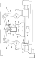
- the work robot system 1 of the present embodiment is predetermined with respect to the transfer device 2 that conveys the article 100 to be worked and the work target portion 101 of the article 100 that is conveyed by the transfer device 2. It is equipped with a robot (following robot) 10 that performs the work of.
- the working robot system 1 includes a control device 20 for controlling the robot 10, a detection device 40 as a detection unit, and a visual sensor 50 attached to the robot 10.
- the detection device 40 detects that the article 100 has been transported to a predetermined position.
- the detection device 40 any device having such a function can be used.
- the detection device 40 is a photoelectric sensor, but the visual sensor 50 may detect that the article 100 has been conveyed to a predetermined position.
- Article 100 is not limited to a specific type of item.
- the article 100 is a car body.
- the transport device 2 transports the article 100 by driving several of the plurality of rollers 3 by the motor 2a.
- the transport device 2 transports the article 100 toward the right side in FIG.
- the work target portion 101 is a portion of the article 100 in which the robot 10 performs a predetermined work.
- the hand (tool) 30 of the robot 10 lifts the component 110, and the robot 10 attaches the attachment portion 111 of the component 110 to the work target portion 101.
- the shaft 111a extending downward from the mounting portion 111 of the component 110 fits into the hole 101a provided in the work target portion 101 of the article 100.
- the robot 10 attaches the attachment portion 111 of the component 110 to the work target portion 101 while the article 100 is being moved by the transfer device 2.
- the robot 10 is not limited to a specific type, but the robot 10 of the present embodiment includes a plurality of servomotors 11 for each of a plurality of movable arms 10a (see FIG. 2).
- Each servomotor 11 has an operating position detecting device for detecting its operating position, and the operating position detecting device is an encoder as an example. The detection value of the operating position detecting device is transmitted to the control device 20.
- a hand 30 is attached to the tip of the arm 10a.
- the hand 30 of the present embodiment supports the component 110 by gripping with a plurality of claws, but it is also possible to use a hand that supports the component 110 by using magnetic force, suction of air, or the like.
- the hand 30 includes a servomotor 31 that drives the claws (see FIG. 2).
- the servomotor 31 has an operating position detecting device for detecting the operating position thereof, and the operating position detecting device is an encoder as an example. The detection value of the operating position detecting device is transmitted to the control device 20.
- various servomotors such as a rotary motor and a linear motion motor can be used.
- a force sensor 32 is attached to the tip of the robot 10.
- the force sensor 32 measures, for example, a force or a moment in the X-axis direction, the Y-axis direction, and the Z-axis direction shown in FIG. 3, and around the X-axis, the Y-axis, and the Z-axis.
- the force sensor 32 may be any as long as it can detect the direction of the force applied to the hand 30 or the component 110 gripped by the hand 30 and the degree of the force. Therefore, in the present embodiment, the force sensor 32 is provided between the robot 10 and the hand 30, but the force sensor 32 may be provided in the hand 30.
- a visual sensor 50 is attached to the tip of the arm 10a.
- the visual sensor 50 is attached to the wrist flange of the robot 10 using a frame 50a.
- the visual sensor 50 is a two-dimensional camera.
- the visual sensor 50 of the present embodiment provides image data as shown in FIG. 3 so that the tracking target 102 whose position and posture do not change relative to the work target portion 101 falls within a predetermined range of the angle of view. Acquire sequentially.
- the follow-up target 102 is the upper surface portion shown by the diagonal line in FIG. 3, but it is also possible to use another portion whose position and posture do not change relative to the work target portion 101.
- the visual sensor 50 may be attached to a tool such as the hand 30. Further, the visual sensor 50 may be attached to another place of the robot 10 whose relative position and posture do not change with the tool such as the hand 30.
- the visual sensor 50 sequentially transmits image data to the control device 20.
- the image data is data that can specify the position and posture of the tracking target 102.
- the image data may be processed by a detector other than the control device 20, and the position and orientation of the tracking target 102 may be specified based on the processed data.
- the follow-up target 102 is a portion of the article 100 having a predetermined shape, a portion provided with a predetermined mark, and the like.
- the image data is data that can determine the position and orientation of the above portion on the image.
- the position and posture of the hand 30 attached to the arm 10a is changed.
- the position and posture of the hand 30 attached to the arm 10a and the position and posture of the visual sensor 50 are associated with each other by calibration.
- the control device 20 recognizes the position and posture of the tracking target 102 in the coordinate system of the robot 10 based on the image data, and the control device 20 uses the hand 30 provided on the arm 10a at a position required for a predetermined work. It can be moved to the posture.
- the shaft 111a of the mounting portion 111 of the component 110 can be fitted into the hole 101a provided in the work target portion 101 of the article 100.
- the article 100 may swing on the transport device 2. For example, if the plurality of rollers 3 of the transport device 2 are not arranged on a perfect plane, the article 100 swings. When the article 100 is large, a slight shaking on the lower end side of the article 100 may lead to a large shaking of the work target portion 101. Therefore, it is important to adjust the posture of the hand 30 provided on the arm 10a.
- changes in the position, posture, and size of the tracking target 102 on the image data of the visual sensor 50 and changes in the position and posture of the coordinate system of the robot 10 are determined in advance in the control device 20. It is related.
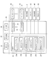
- the control device 20 includes a control unit 21 having a CPU, RAM, and the like, a display device 22, and a storage unit (feature amount storage unit, input value storage unit) having a non-volatile storage, ROM, and the like. It is equipped with 23. Further, the control device 20 is connected to a plurality of servo controllers 24 corresponding to the servomotors 11 of the robot 10, a servo controller 25 corresponding to the servomotor 31 of the hand 30, and a control device 20. It also has an input unit 26. In one example, the input unit 26 is an input device such as an operation panel that can be carried by the operator. The input unit 26 may perform wireless communication with the control device 20.
- the system program 23a is stored in the storage unit 23, and the system program 23a has a basic function of the control device 20. Further, the operation program 23b is stored in the storage unit 23. Further, the storage unit 23 includes a follow-up control program (movement command means) 23c, a force control program 23d, a feature amount detection program (feature amount detection means) 23e, and a movement amount calculation program (movement amount calculation means) 23f. Is stored.
- the signal acquired when the specific operation of the follow-up target 102 starts and the input value of the feedforward control are stored in association with each other.
- the specific operation of the follow-up target 102 is an unsteady operation assumed during the operation of the transport device 2 for transporting the article 100, and is a stop, a restart from the stop, or an emergency stop due to another work process. Etc.
- a signal capable of specifying each specific operation is acquired by the control device 20.
- control unit 21 transmits a movement command for performing a predetermined work on the article 100 to the servo controllers 24 and 25.
- the robot 10 and the hand 30 perform a predetermined operation on the article 100.
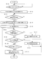
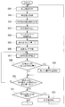
- the operation of the control unit 21 at this time will be described with reference to the flowchart of FIG.
- step S1-1 when the article 100 is detected by the detection device 40 (step S1-1), the control unit 21 starts transmitting a pre-work movement command to the robot 10 and the hand 30 based on the operation program 23b (step S1). -2). As a result, the robot 10 brings the shaft 111a of the component 110 gripped by the hand 30 closer to the hole 101a of the work target portion 101. At this time, the control unit 21 may use data such as the transfer speed of the transfer device 2, the position data of the work target unit 101 in the article 100, and the like. Further, after step S1-4 described later, the shaft 111a of the component 110 is fitted into the hole 101a of the article 100 based on the operation program 23b. In step S1-1, the article 100 may be detected by the visual sensor 50 instead of the detection device 40.
- step S1-2 Under the control of the robot 10 in step S1-2, the component 110 reaches a predetermined work (fitting) preparation position and posture.
- the control unit 21 controls the tracking control program 23c.
- Control based on the feature amount detection program 23e and the movement amount calculation program 23f is started (step S1-4).
- step S1-4 for example, the following control is performed.
- at least the position and posture of the tracking target 102 are detected based on the image data of the visual sensor 50, and the control unit 21 is attached to the arm 10a based on the detected position and posture of the visual sensor 50.
- the position and posture are made to follow the tracking target 102.
- the hand 30 of the robot 10 is an article in such a manner that the tracking target 102 is always arranged at the target position and posture of the image data of the visual sensor 50.
- follow 100 Such control is realized by, for example, the following control.
- the storage unit 23 stores the target position, the target posture, and the target size to which the follow-up target 102 should be arranged in the image data as the first feature amount.
- the target size is, for example, the size of the contour when the feature is the contour.
- the control unit 21 Based on the feature amount detection program 23e, the control unit 21 detects the position, posture, and size of the tracking target 102 on the image data sequentially obtained by the visual sensor 50 as the detection of the second feature amount.
- the control unit 21 projects and transforms the model of the tracking target 102 stored in the storage unit 23, and performs a matching search between the projected model and the tracking target 102 on the image data to perform a tracking target.
- the position and orientation of 102 are detected.
- the model may be created using CAD data or the like, or may be created from an actual object. Since the relative position and the relative posture of the work target unit 101 and the follow-up target 102 are fixed, the control unit 21 has the relative position and the relative position of the tip portion of the arm 10a and the follow-up target 102 based on the position and the posture of the follow-up target 102. You can get a relative posture.
- the control unit 21 calculates a movement command for matching the position, posture, and size of the tracking target 102 in the image data with the first feature amount based on the movement amount calculation program 23f.
- the calculated movement command is for eliminating or reducing the difference between the position, posture, and size of the tracking target 102 in the image data and the first feature amount.
- the calculated movement command changes, for example, the position of the hand 30 attached to the arm 10a in the X-axis direction, the Y-axis direction, and the Z-axis direction, and changes the posture of the hand 30 around the X-axis, around the Y-axis, and around the Y-axis. It is changed around the Z axis.
- the control unit 21 may further adjust the calculated movement command based on the parameters determined by the mechanical characteristics of the arm 10a.
- the mechanical properties include the rigidity of the entire or part of the arm 10a, the rigidity of each movable part, the weight of the hand 30, the weight of the component 110, the moment received by the arm 10a due to the weight of the hand 30 and the component 110, and the like. Is done. Further, since the amount of bending, the direction, and the like of the arm 10a change according to the angle of the joint which is the movable portion of the arm 10a, the state of each movable portion of the arm 10a is also included in the mechanical properties.
- the posture of the arm 10a changes due to the movement command
- the moment received by the arm 10a, the state of each movable part of the arm 10a, etc. change depending on the weight of the hand 30 and the component 110, etc., according to the posture change. Therefore, if the movement command is adjusted in consideration of these mechanical characteristics, the hand 30 can be made to follow the article 100 more accurately.
- the control unit 21 can obtain the tendency of the change of the second feature amount by using a plurality of continuous image data. For example, when the position, posture, and size of the follow-up target 102 on the image data of the visual sensor 50 are gradually approaching the first feature amount which is the target data, a plurality of continuous image data are used with respect to the follow-up target 102. The tendency of changes in the relative position and relative posture of the visual sensor 50 can be captured.
- control unit 21 may adjust the movement command based on the movement amount calculation program 23f using feedforward control based on the tendency.
- the average speed may be obtained from the change in the amount of movement, and the basic speed may be given as feedforward control.
- feedforward control it is possible to feedback control the deviation while keeping the relative speed with the target constant to some extent. If feedforward is not used, there may be a moment when the moving speed of the robot becomes 0 when the features of the images match. In this case, deceleration and acceleration may occur frequently, but such deceleration and acceleration can be prevented by using feedforward control.
- the correction data to which feedforward is applied is subjected to well-known filtering processing such as moving average, smoothing processing, and the like.
- filtering processing such as moving average, smoothing processing, and the like.
- the input value such as the basic speed given to the feedforward control may be arbitrarily input by the user based on the one measured by an external measuring instrument. Further, the vibration of the arm may be reduced by creating a robot model in consideration of the deflection (twist) of the speed reducer and estimating and feeding back the vibration of the arm.
- feedforward control is performed on the assumption that the follow-up target 102 performs a specific operation as a case where the relative position and the relative posture tend to change. That is, when the signal when the follow-up target 102 starts the specific operation is acquired, the input value stored in the storage unit 23 is read out in association with the signal, and the feedforward control is performed based on the input value. I do.
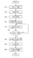
- the input value of the feedforward control is acquired in advance by the following method. First, as shown in FIG. 5, a visual sensor 50 fixed to the floor surface to which the transport device 2 is fixed is prepared.
- the tracking target 102 is arranged within the angle of view of the visual sensor 50, and the visual sensor 50 is operated (step S10). Then, the above-mentioned specific operation is executed (step S11). For example, when the emergency stop of the transport device 2 is executed, an emergency stop signal (specific signal) capable of specifying the emergency stop is acquired by the control device 20 (step S12).
- an emergency stop signal specific signal capable of specifying the emergency stop is acquired by the control device 20 (step S12).
- the follow-up target 102 vibrates in the trajectory shown in FIG.
- the image data including the follow-up target 102 is sequentially acquired by the visual sensor 50 at minute time intervals, and the position of the follow-up target 102 is sequentially detected by processing the acquired image data ( Step S13).
- step S14 the change in the position of the detected follow-up target 102 is determined (step S14), and when the change in the position exceeds a predetermined threshold value, the process from step S13 is repeated.
- step S14 the change in position becomes equal to or less than a predetermined threshold value in step S14, the locus of the tracking target 102 in the robot coordinate system is calculated from the information on the position of the tracking target 102 acquired in time series (step S15). ).
- the input value of the feedforward control is calculated based on the locus of the follow-up target 102 (step S16). Specifically, as shown in FIG. 7, the input value of the feedforward control is calculated as a command signal that matches the locus of the robot 10 with the locus of the follow-up target 102.
- the calculated input value is a command signal that changes over a finite time interval, and is stored in association with a signal that can specify the acquired specific operation (step S17).
- the input value of the feedforward control is calculated in the same manner for the specific operation other than the emergency stop, and is stored in the storage unit 23 in association with the signal capable of specifying each specific operation.
- step S20 a specific operation of the follow-up target 102 is generated.
- the control device 20 acquires a specific signal capable of specifying the specific operation (step S21).
- the control device 20 reads out the input value stored in the storage unit 23 in association with the acquired specific signal (step S22), and feedforward control is performed in which the input value is added to the sequential command signal at predetermined minute time intervals. Start (step S23). At this time, an image including the follow-up target 102 is acquired by the visual sensor 50 provided in the robot 10 (step S24), and the acquired image is processed to detect the position of the follow-up target 102 on the image (step S25). ..
- step S26 it is sequentially determined whether or not the detected position of the follow-up target 102 is within a predetermined range (step S26), and if the position is deviated beyond the predetermined range, the position of the follow-up target 102 is determined.
- the direction of deviation and the amount of displacement are stored in association with the time of the input value (step S27).
- step S28 it is determined whether or not the input value is completed (step S28), and from step S25 until the input value is completed. The process is repeated.
- the feedforward control input value stored in the storage unit 23 is corrected based on the position shift of the stored tracking target 102 (step S29).
- the input value may be finely adjusted by repeating the steps from step S20 to step S29 until the positional deviation of the tracking target 102 becomes equal to or less than a predetermined range with respect to the input value over the entire period.
- the tool 30 of the robot 10 can be accurately followed by the article 100 even if a non-steady operation of the transfer device 2 occurs during actual work using the robot 10 according to the present embodiment.
- the visual sensor 50 provided in the robot 10 is used when setting the input value of the feedforward control, there is an advantage that the setting can be easily performed.
- the visual sensor 50 may be prepared separately from the visual sensor 50 attached to the robot 10. In this case, the visual sensor 50 fixedly installed on the floor surface is calibrated with respect to the coordinate system of the robot 10. When the visual sensor 50 attached to the robot 10 is used, the robot 10 is kept stationary. In this case, the visual sensor 50 is calibrated with respect to the coordinate system of the robot 10.
- control unit 21 may interpolate the detection result of the second feature amount by using the tendency of changes in the relative position and the relative posture. Therefore, even if the acquisition cycle of the second feature amount is as long as the imaging cycle of the visual sensor 50, the second feature amount can be estimated during the acquisition cycle by interpolating the detection result, and in the future. It is possible to estimate the second feature amount.
- control unit 21 causes the hand 30 of the arm 10a to follow the work target unit 101.
- the position and posture of the shaft 111a of the mounting portion 111 of the component 110 and the position and posture of the hole 101a of the work target portion 101 coincide with each other.
- the change in the position, posture, and size of the tracking target 102 on the image data of the visual sensor 50 and the change in the position and posture of the coordinate system of the robot 10 are related in the control device 20. It is attached. Therefore, when the visual sensor 50 is following the tracking target 102, the coordinate system of the robot 10 moves in the transport direction of the transport device 2, and the position and posture of the coordinate system match the movement of the article 100 by the transport device 2. be able to. In this situation, the work target unit 101 of the article 100 is moved by the transport device 2, but when viewed from the control unit 21, the work target unit 101 appears to be almost stopped in the coordinate system.
- the control unit 21 starts force control based on the force control program 23d (step S1-5).
- the force control a well-known force control can be used.
- the robot 10 moves the component 110 in a direction to escape from the force detected by the force sensor 32.
- the amount of movement is determined by the control unit 21 according to the detected value of the force sensor 32.
- the force sensor 32 detects a force in the direction opposite to the transport direction by the transport device 2.
- the control unit 21 slightly moves the component 110 in the direction opposite to the transport direction to escape from the detected force.
- the control unit 21 performs the first abnormality response operation when the second feature amount sequentially detected based on the image data of the visual sensor 50 fluctuates beyond a predetermined reference (step S1-6).
- Fluctuations exceeding a predetermined reference include a large movement of the tracking target 102 in the image data, a movement faster than the predetermined speed of the tracking target 102 in the image data, and the like. If the power supply is not stable, the rotation speed of the motor 2a may drop sharply, and the rotation speed of the motor 2a may fluctuate significantly. In these cases, the position of the tracking target 102 with respect to the tip end portion of the arm 10a will fluctuate beyond a predetermined reference.
- the control unit 21 operates to shorten the control cycle of force control or increase the sensitivity, to stop the progress of fitting, to stop the fitting work, and what is the fitting direction.
- the operation of retracting in the opposite direction, the operation of stopping the transportation, or the operation of combining them is performed.
- the control unit 21 performs an operation of stopping the fitting operation, an operation of retracting in the direction opposite to the fitting direction, an operation of stopping the transport device 2, or an operation in which they are combined.
- step S1-8 when the second feature amount is equal to or less than a predetermined reference value in step S1-6 and the detected value of the force sensor 32 exceeds the predetermined reference value (step S1-8), the control unit 21 has a second abnormality. The corresponding operation is performed (step S1-9).
- the control unit 21 performs the following operation as the second abnormality response operation.
- an operation of stopping the robot 10 an operation of moving the robot 10 in a direction of escaping from the direction of the force detected by the force sensor 32, an operation of stopping the transport device 2, an operation of retracting in the direction opposite to the fitting direction, and an operation of retracting.
- the operation of stopping the transportation or the operation of combining them is performed.
- the control unit 21 operates to stop the robot 10.
- step S1-8 determines whether or not the fitting operation is completed (for example, the traveling distance in the Z direction is a predetermined value).
- Step S1-10 determines whether or not the fitting operation is completed (for example, the traveling distance in the Z direction is a predetermined value).
- Step S1-10 determines whether or not the fitting operation is completed (for example, the traveling distance in the Z direction is a predetermined value).
- a predetermined movement command or operation command is sent to the arm 10a and the hand 30 (step S1-11).
- the hand 30 releases the component 110 and moves away from the component 110, and the hand 30 moves to the standby position or the place where the next component 110 is stocked by the arm 10a. If it is determined in step S1-10 that the fitting operation has not been completed, the steps from step S1-6 are repeated.
- control unit 21 performs a wide range detection process for detecting the second feature amount in the first range in the image data based on the feature amount detection program 23e, and the image data obtained thereafter.
- the narrow range detection process may be performed in the second range.
- the narrow range detection process is a process of detecting a second feature amount in a second range narrower than the first range.
- the difference between the first feature amount and the second feature amount is large, a wide range detection process is performed, and when the difference between the first feature amount and the second feature amount becomes a predetermined value or less, a narrow range detection is performed. Processing is done. As a result, when the difference between the first feature amount and the second feature amount becomes small, it becomes possible to improve the processing speed, the processing accuracy, and the like.
- the control unit 21 sets the area including the tracking target 102 detected in the image data as the detection range of the second feature amount based on the feature amount detection program 23e. May be good.
- the detection range can be set by setting the circumscribed rectangle in contact with the contour of the detected follow-up target 102 and enlarging the circumscribed rectangle by a predetermined magnification.
- the magnification may be changed according to the size (size) of the tracking target 102 in the image data, the distance between the visual sensor 50 and the tracking target 102, and the like. For example, when the visual sensor 50 and the follow-up target 102 come close to each other, the amount of movement of the follow-up target 102 on the image in the image data increases, so that the magnification is increased. As a result, the position and orientation of the tracking target 102 can be detected efficiently and accurately.
- the hand 30 as a tool may be attached to a working robot 60 which is another robot.
- the arm 60a and the hand 30 of the working robot 60 are controlled by the control device 70.
- the control device 70 has the same configuration as the control device 20, and the arm 60a also has the same configuration as the arm 10a.
- the position and direction of the coordinate system of the visual sensor 50 and the position and direction of the coordinate system of the robot 60 are related in the control device 70.
- the control device 70 operates the robot 60 in the coordinate system of the robot 60 while the control unit 21 makes the visual sensor 50 follow the tracking target 102. Since the position and posture of the coordinate system of the robot 60 change according to the position and posture of the coordinate system of the visual sensor 50, the control device 70 performs the work using the operation program 23b set based on the coordinate system of the robot 60. be able to.
- the control device 20 follows the position and posture of the visual sensor 50 to the tracking target 102, the information of the movement command, the difference between the second detection amount and the first detection amount.
- the position and posture of the coordinate system of the robot 60 can be made to follow the work target portion 101 based on the information and the like. Therefore, when the robot 60 performs the work of fitting the shaft 111a of the component 110 into the hole 101a of the article 100 based on the operation program 23b, the hand 30 of the robot 60 follows the article 100.
- the control device 20 and the control device 70 may be connected to a higher-level control system such as a production control system, and information may be exchanged between the control device 20 and the control device 70 via the higher-level control system.
- a higher-level control system such as a production control system
- the robot 60 it is also possible to use a robot having a rail provided above the transport device 2 along the transport device 2 and a movable arm movably attached to the rail.
- the visual sensor 50 is attached to the tip of the movable arm, and the movable arm can change the posture of the tip and the visual sensor 50, for example, around the X-axis and around the Y-axis.
- the movable arm can move the position of the tip and the visual sensor 50 in the Y-axis direction, but even if the movable arm cannot freely move the position of the tip and the visual sensor 50 in the Y-axis direction. good. Even in this case, the position and posture of the visual sensor 50 attached to the movable arm can be made to follow the tracking target 102.
- the position of the visual sensor 50 attached to the movable arm in the X-axis direction is based on the difference between the second feature amount and the first feature amount.
- X-axis and Y-axis postures can be made to follow the follow-up target 102. If the tracking can be performed, even if the tracking target 102 may move in the Y-axis direction in the image data, the movement amount can be detected and the same effect as described above can be obtained.
- the storage unit 23 stores the first feature amount related to the shape and the like of the follow-up target 102. Since the shape of the tracking target 102 changes according to the distance and angle between the arm 10a and the tracking target 102, the tracking control can be performed more accurately.
- a plurality of visual sensors 50 are used, and it is also possible to make the plurality of visual sensors 50 follow each of the plurality of tracking targets 102.
- the follow-up target 102 is arranged at each predetermined position in the plurality of image data obtained by the plurality of visual sensors 50
- the hand 30 attached to the arm 10a refers to the work target portion 101 of the article 100. It is also possible to determine that they are placed in a predetermined position and posture.
- the robot 10 of the present embodiment has the first target data for making the at least one visual sensor 50 provided on the arm 10a and the visual sensor 50 provided on the arm 10a follow the tracking target 102.
- a storage unit 23 for storing a feature amount is provided. Then, in the present embodiment, the second feature amount relating to the current at least position and posture of the follow-up target 102 is detected by using the image obtained by the visual sensor 50.
- the movement command of the arm 10a is calculated based on the difference between the second feature amount and the first feature amount. Further, while the visual sensor 50 follows the tracking target 102, the calculation of the movement command and the movement of the arm based on the movement command are repeated. Therefore, the relative position and the relative posture of the hand 30 with respect to the article 100 transported by the transport device 2 can be gradually brought closer to the target data. This is useful for accurately following the operation of the arm 10a of the robot 10 with the article 100 being conveyed by the conveying device 2.
- the model of the follow-up target 102 is provided as the first feature amount.
- the control unit 21 performs a matching search between the feature unit in the image data obtained by the visual sensor 50 and the projected model, thereby performing a matching search for the feature in the image data.
- the position and posture of the portion (second feature amount) can be obtained.
- This configuration is useful for accurately approaching the relative position and posture of the visual sensor 50 with respect to the tracking target 102 of the article 100 transported by the transport device 2 to the target data.
- the feature portion may be a figure provided on the surface of the article 100.
- the movement command is adjusted by using at least feedforward control.
- the feedforward control is performed in consideration of the movement tendency of the article 100 by the transport device 2, which quickly uses the relative position and the relative posture of the visual sensor 50 with respect to the tracking target 102 of the article 100 as target data. Useful for getting closer.
- the control unit 21 uses the data obtained by the visual sensor 50 or another sensor 40 to set the tracking target 102 of the visual sensor 50. Calculate the pre-work movement command to put it within the detection range. Therefore, the visual sensor 50 is arranged at a position required for tracking in a short time before the tracking control of the arm 10a is performed.
- the work robot system of the present embodiment includes a transfer device 2 and a robot 10, and the robot 10 is designated as an article 100 in a state where the visual sensor 50 provided in the robot 10 is following the tracking target 102. Do the work of.
- the working robot 60 is an article while using the information of the movement command for making the visual sensor 50 provided in the robot 10 follow the tracking target 102 or the information used for calculating the movement command. Perform the predetermined work on 100.
- the work robot 60 When the work robot 60 is used, it is possible to perform a predetermined work on the article 100 at a place away from the visual sensor 50.
- a plurality of working robots 60 may perform a predetermined work on the article 100 by using the above-mentioned information.
- the work robot system of the present embodiment further includes a force sensor 32.
- the force sensor 32 is a force generated by the contact of the component 110 or the hand 30 supported by the robot 10 with the article 100, or the contact of the component 110 or the hand 30 supported by the working robot 60 with the article 100. Detects the force generated by.
- the hand 30 provided on the robot 10 or the work robot 60 is used as the article 100 while using the detection value of the force sensor 32.
- the accuracy of the follow-up control can be further improved.
- the follow-up target 102 is a part of the article 100.
- the position of the tracking target 102 in the article 100 is fixed, which is useful for further improving the accuracy of the tracking control.
- the processing tool may be supported on the tip of the robot 10 or the work robot 60, and the robot 10 or the work robot 60 may process the article 100 conveyed by the transfer device 2 as a predetermined work.
- the machining tool is a drill, a milling cutter, a drill tap, a deburring tool, other tools, and the like.
- the processing tool may be a welding gun, a welding torch, or the like.
- the transport device 2 it is possible to use a transport device that transports the article 100 along a curved route, and it is also possible to use a transport device that transports the article 100 along a winding route. Even in these cases, the control unit 21 can make the tip portion of the robot 10 or the work robot 60 follow the work target unit 101 by using the detection result of the visual sensor 50.
- control unit 21 can perform the first abnormality response operation in step S1-7. Therefore, even when the transport device is used, the same effect as described above is achieved.
- another robot may move the article 100. Even in this case, the same effects as described above can be achieved. Further, when the article 100 is an automobile, a frame of an automobile, or the like, the article 100 on which a predetermined work is performed may be moved by its engine, wheels, or the like. In these cases, other robots, engines, wheels, etc. function as transport devices.
- AGV Automated Guided Vehicle
- the article 100 may be transported by a shooter in which the article 100 slides down, rolls down, or falls due to gravity. In this case, it is also possible to vibrate the tilted shooter with a vibration exciter, thereby smoothing the movement of the article 100 on the shooter. In these cases, the shooter, the vibration device, and the like function as a transport device, and the article 100 moved by the shooter is taken out by a tool attached to the robot 10.
- the force sensor 32 is attached to the tip of the robot 10 or the working robot 60.
- the force sensor 32 it is also possible to arrange the force sensor 32 between the transport device 2 and the article 100, inside the article 100, or the like. Even in this case, it is possible to perform force control based on the detected value of the force sensor 32, and the same effect as described above is achieved.
- the visual sensor 50 may be attached to a portion other than the wrist flange of the robot 10 or the working robot 60.
- the visual sensor 50 may be a stereo camera. In this case, it is possible to obtain the distance image data of the follow-up target 102 by a pair of cameras, and the position and the posture of the follow-up target 102 are specified by using the image data and the corresponding three-dimensional model.
- the target followed by the visual sensor 50 and the work target of the robot 10 are different, but the target followed by the visual sensor 50 and the work target of the robot 10 may be the same.
- the target followed by the visual sensor 50 and the work target of the robot 10 may be the same.
- the target to be worked on and the target to be worked on can be the same.
- the position, posture, and size of the tracking target 102 are arranged at the target position on the image data of the visual sensor 50, whereby the position and posture of the hand 30 as a tool are determined with respect to the article 100. Place in the position and posture required for the work.
- the position and posture of the tracking target 102 are placed at the target position on the image data of the visual sensor 50, whereby the position and posture of the tool attached to the robot 10 are set to the positions and postures required for the predetermined work. It may be arranged.
- the first method is used.
- the size information as a feature quantity and the size information as a second feature quantity may not be used.
- the one that calculates the locus of the follow-up target 102 in the robot coordinate system is exemplified, but the specific operation of the follow-up target 102 in the robot coordinate system (for example, the stop operation or the restart from the stopped state) is illustrated. Only the elapsed time of the operation) may be calculated and used as the time constant of the specific operation.
- Step S31 When the change in position becomes equal to or less than a predetermined threshold value in step S14, the time when the tracking target 102 is stopped is stored in the storage unit 23 as the specific operation stop time (step S32).
- the elapsed time is calculated as the difference between the stored specific operation start time and the specific operation stop time (step S33), and the calculated elapsed time is used as a time constant to specify each specific operation of the follow target 102. It is stored in the storage unit 23 in association with the above (step S34).
- the specific operation ends (for example, when the speed becomes constant after the operation is completely stopped or the operation is restarted from the stopped state).
- the operator visually determines the stop of the follow target 102 without using the visual sensor 50, and uses a measuring device such as a stop watch. The elapsed time may be measured. If the time constant can be specified from the setting of the inverter of the transport device 2, the time constant specified from the setting may be used as it is.
- step S40 a specific operation of the follow-up target 102 is generated.
- the control device 20 stores the time when the specific signal is acquired in the storage unit 23 as the specific operation start time after the specific signal that can specify the specific operation is acquired (step S41) (step S41).
- step S42 the time constant set by the control device 20 is read from the storage unit 23 (step S43), and feed forward control is started according to the set time constant (step S44).
- step S45 the initial value of the maximum misalignment amount of the follow-up target 102 is set to 0 (step S45).
- step S46 an image including the follow-up target 102 is acquired by the visual sensor 50 provided in the arm 10a of the robot 10 (step S46), and the acquired image is processed to detect the position of the follow-up target 102 on the image (step). S47).
- step S48 it is determined whether or not the absolute value of the detected misalignment of the tracking target 102 is larger than the absolute value of the stored maximum misalignment (step S48), and the misalignment of the tracking target 102 is determined.
- the absolute value of is larger than the absolute value of the maximum misalignment amount
- the maximum misalignment amount is updated and stored in the storage unit 23 (step S49).
- step S50 the process from step S47 is repeated.
- the tracking target 102 and the robot 10 are stopped, so that the amount of change in the positional deviation becomes 0. Further, when the specific operation is restarted from the stop, the tracking target 102 and the robot 10 become constant speeds, and if the speeds are the same, the amount of change in the position shift becomes 0, and if there is a speed difference, the position shift occurs.
- the amount of change over time is a non-zero constant value.
- Step S51 After a lapse of time from the set time constant and the time change amount of the change amount of the position shift becomes a constant value, it is determined whether or not the absolute value of the maximum position shift amount becomes larger than the predetermined threshold value. (Step S51).
- the absolute value of the maximum misalignment amount is equal to or less than a predetermined threshold value, it is determined whether to increase or decrease the time constant according to the sign of the maximum misalignment amount, and the absolute value of the maximum misalignment amount is determined.
- the amount is added to or subtracted from the time constant, and the time constant of the feed forward control stored in the storage unit 23 is updated (step S52).
- the increase / decrease amount ⁇ T according to the absolute value of the maximum misalignment amount may be calculated by, for example, the following equation (1).
- ⁇ T D / V (1)
- D is the maximum amount of misalignment
- V is the constant speed of the tracking target 102.
- step S51 the process is repeated from step S40 until the absolute value of the maximum misalignment amount becomes equal to or less than the predetermined threshold value, and when the absolute value of the maximum misalignment amount becomes equal to or less than the predetermined threshold value, the process ends.
- the follow-up target 102 accelerates or decelerates immediately from the time when a specific signal capable of specifying a specific operation is acquired to execute the specific operation, but instead of this, the time when the specific signal is acquired.
- the follow-up target 102 may be accelerated or decelerated corresponding to a specific signal at predetermined time intervals. In this case, an arbitrary time is set as the predetermined time interval.
- the input value of the feedforward control acquired by the above method is the same as the transport device 2 for transporting the article 100 (the same transport device as an object, or the same specifications and settings. It may be used for another robot that works on the transport device).
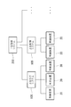
- a plurality of control devices 20 may be connected to the host control system 100.
- the host control system 100 is, for example, a computer connected to a plurality of control devices 20 by wire, a computer arranged on the same site as the plurality of control devices 20, and the like.
- the host control system 100 is sometimes referred to as a fog computer.
- the upper control system 100 may be a production management system, a shipping management system, a robot management system, a department management system, or the like.
- a plurality of higher control systems 100 may be connected to another higher control system 200 or the like.
- the other higher control system 200 is, for example, a cloud server connected to a plurality of higher control systems 100 by wire or wirelessly.
- a management system is formed by a plurality of control devices 20 and an upper control system 100.
- the host control system 100 includes a control unit having a processor and the like, a display device, a storage unit having a non-volatile storage, a ROM, a RAM, and the like, and an input device such as a keyboard, a touch panel, and an operation panel, respectively. ..
- Such a system may include, for example, a plurality of edge computers 8, a plurality of superior control systems 100, and a single or plurality of other superior control systems 200, as shown in FIG.
- the control device 20 and the robot 10 can be edge computers.
- a part of the control device 20 and the robot 10 may be an upper control system.
- Such systems include wired or wireless networks.
- Robot following robot
- 10a arm 23 storage unit (feature quantity storage unit, input value storage unit)
- 23c Follow-up control program (movement command means)
- 23e Feature detection program (feature detection means)
- 23f Movement amount calculation program (movement amount calculation means) 50
- Visual sensor 102
Landscapes
- Engineering & Computer Science (AREA)
- Robotics (AREA)
- Mechanical Engineering (AREA)
- Human Computer Interaction (AREA)
- Manipulator (AREA)
Abstract
Priority Applications (4)
| Application Number | Priority Date | Filing Date | Title |
|---|---|---|---|
| JP2022524432A JP7448648B2 (ja) | 2020-05-19 | 2021-05-14 | 追随ロボットおよび制御装置 |
| DE112021001603.2T DE112021001603B4 (de) | 2020-05-19 | 2021-05-14 | Folgeroboter |
| US17/918,400 US12515343B2 (en) | 2020-05-19 | 2021-05-14 | Following robot |
| CN202180035701.7A CN115605329B (zh) | 2020-05-19 | 2021-05-14 | 随动机器人 |
Applications Claiming Priority (2)
| Application Number | Priority Date | Filing Date | Title |
|---|---|---|---|
| JP2020-087367 | 2020-05-19 | ||
| JP2020087367 | 2020-05-19 |
Publications (1)
| Publication Number | Publication Date |
|---|---|
| WO2021235331A1 true WO2021235331A1 (fr) | 2021-11-25 |
Family
ID=78708389
Family Applications (1)
| Application Number | Title | Priority Date | Filing Date |
|---|---|---|---|
| PCT/JP2021/018348 Ceased WO2021235331A1 (fr) | 2020-05-19 | 2021-05-14 | Robot suiveur |
Country Status (5)
| Country | Link |
|---|---|
| US (1) | US12515343B2 (fr) |
| JP (1) | JP7448648B2 (fr) |
| CN (1) | CN115605329B (fr) |
| DE (1) | DE112021001603B4 (fr) |
| WO (1) | WO2021235331A1 (fr) |
Cited By (2)
| Publication number | Priority date | Publication date | Assignee | Title |
|---|---|---|---|---|
| CN114928813A (zh) * | 2022-05-20 | 2022-08-19 | 上汽通用五菱汽车股份有限公司 | 行人目标跟随方法、装置、电子设备及可读存储介质 |
| JP2023142520A (ja) * | 2022-03-25 | 2023-10-05 | セイコーエプソン株式会社 | ロボットシステムの制御方法およびロボットシステム |
Families Citing this family (2)
| Publication number | Priority date | Publication date | Assignee | Title |
|---|---|---|---|---|
| US20250058478A1 (en) * | 2021-12-21 | 2025-02-20 | Fanuc Corporation | Control device and machine system |
| CN120816496B (zh) * | 2025-09-15 | 2025-12-30 | 北京小雨智造科技有限公司 | 机械臂的控制方法、装置、设备和存储介质 |
Citations (3)
| Publication number | Priority date | Publication date | Assignee | Title |
|---|---|---|---|---|
| JP2001252886A (ja) * | 2000-03-10 | 2001-09-18 | Hitachi Zosen Corp | 物体のハンドリングシステム |
| JP2018083284A (ja) * | 2016-11-11 | 2018-05-31 | セイコーエプソン株式会社 | ロボット制御装置、ロボット、ロボットシステム、及び、ロボット制御方法 |
| JP2019136808A (ja) * | 2018-02-08 | 2019-08-22 | ファナック株式会社 | 作業ロボットシステム |
Family Cites Families (19)
| Publication number | Priority date | Publication date | Assignee | Title |
|---|---|---|---|---|
| US3744032A (en) * | 1971-07-15 | 1973-07-03 | Unimotion Inc | Stationary base programmed manipulator arrangement for continuously moving workpiece |
| US4675502A (en) * | 1985-12-23 | 1987-06-23 | General Electric Company | Real time tracking control for taught path robots |
| JPH0872764A (ja) * | 1994-09-01 | 1996-03-19 | Mazda Motor Corp | 生産ライン制御装置 |
| JP2006015431A (ja) * | 2004-06-30 | 2006-01-19 | Denso Wave Inc | ロボットの制御装置及び制御方法 |
| JP2007066001A (ja) | 2005-08-31 | 2007-03-15 | Nachi Fujikoshi Corp | ロボットの制御装置 |
| WO2009123956A1 (fr) * | 2008-03-31 | 2009-10-08 | Abb Research | Assemblage de pièces par robot sur une pièce à travailler se déplaçant sur une chaîne d'assemblage |
| EP2216145B1 (fr) * | 2009-02-06 | 2011-06-08 | Honda Research Institute Europe GmbH | Apprentissage et utilisation de schémas dans des dispositifs robotiques |
| US8244402B2 (en) * | 2009-09-22 | 2012-08-14 | GM Global Technology Operations LLC | Visual perception system and method for a humanoid robot |
| JP5508895B2 (ja) * | 2010-02-22 | 2014-06-04 | 本田技研工業株式会社 | 加工システム及び加工方法 |
| JP5505138B2 (ja) * | 2010-07-05 | 2014-05-28 | 株式会社安川電機 | ロボット装置およびロボット装置による把持方法 |
| JP5765557B2 (ja) * | 2011-02-28 | 2015-08-19 | 株式会社Ihi | 加工ロボットの軌道追従装置と方法 |
| JP6430986B2 (ja) * | 2016-03-25 | 2018-11-28 | ファナック株式会社 | ロボットを用いた位置決め装置 |
| JP6795471B2 (ja) * | 2017-08-25 | 2020-12-02 | ファナック株式会社 | ロボットシステム |
| JP6810087B2 (ja) | 2018-03-29 | 2021-01-06 | ファナック株式会社 | 機械学習装置、機械学習装置を用いたロボット制御装置及びロボットビジョンシステム、並びに機械学習方法 |
| US11584016B2 (en) | 2018-04-24 | 2023-02-21 | Fanuc Corporation | Robot controller and system |
| JP6836606B2 (ja) | 2018-04-24 | 2021-03-03 | ファナック株式会社 | ロボット制御装置およびシステム |
| JP7000361B2 (ja) | 2019-01-24 | 2022-01-19 | ファナック株式会社 | 追随ロボットおよび作業ロボットシステム |
| US10549928B1 (en) * | 2019-02-22 | 2020-02-04 | Dexterity, Inc. | Robotic multi-item type palletizing and depalletizing |
| US11741566B2 (en) * | 2019-02-22 | 2023-08-29 | Dexterity, Inc. | Multicamera image processing |
-
2021
- 2021-05-14 JP JP2022524432A patent/JP7448648B2/ja active Active
- 2021-05-14 CN CN202180035701.7A patent/CN115605329B/zh active Active
- 2021-05-14 DE DE112021001603.2T patent/DE112021001603B4/de active Active
- 2021-05-14 WO PCT/JP2021/018348 patent/WO2021235331A1/fr not_active Ceased
- 2021-05-14 US US17/918,400 patent/US12515343B2/en active Active
Patent Citations (3)
| Publication number | Priority date | Publication date | Assignee | Title |
|---|---|---|---|---|
| JP2001252886A (ja) * | 2000-03-10 | 2001-09-18 | Hitachi Zosen Corp | 物体のハンドリングシステム |
| JP2018083284A (ja) * | 2016-11-11 | 2018-05-31 | セイコーエプソン株式会社 | ロボット制御装置、ロボット、ロボットシステム、及び、ロボット制御方法 |
| JP2019136808A (ja) * | 2018-02-08 | 2019-08-22 | ファナック株式会社 | 作業ロボットシステム |
Cited By (3)
| Publication number | Priority date | Publication date | Assignee | Title |
|---|---|---|---|---|
| JP2023142520A (ja) * | 2022-03-25 | 2023-10-05 | セイコーエプソン株式会社 | ロボットシステムの制御方法およびロボットシステム |
| JP7831063B2 (ja) | 2022-03-25 | 2026-03-17 | セイコーエプソン株式会社 | ロボットシステムの制御方法およびロボットシステム |
| CN114928813A (zh) * | 2022-05-20 | 2022-08-19 | 上汽通用五菱汽车股份有限公司 | 行人目标跟随方法、装置、电子设备及可读存储介质 |
Also Published As
| Publication number | Publication date |
|---|---|
| US20230138649A1 (en) | 2023-05-04 |
| CN115605329B (zh) | 2025-09-05 |
| DE112021001603T5 (de) | 2022-12-29 |
| JP7448648B2 (ja) | 2024-03-12 |
| US12515343B2 (en) | 2026-01-06 |
| JPWO2021235331A1 (fr) | 2021-11-25 |
| CN115605329A (zh) | 2023-01-13 |
| DE112021001603B4 (de) | 2026-02-19 |
Similar Documents
| Publication | Publication Date | Title |
|---|---|---|
| JP7000361B2 (ja) | 追随ロボットおよび作業ロボットシステム | |
| JP7448648B2 (ja) | 追随ロボットおよび制御装置 | |
| US11904483B2 (en) | Work robot system | |
| JP7314475B2 (ja) | ロボット制御装置、及び、ロボット制御方法 | |
| US11241796B2 (en) | Robot system and method for controlling robot system | |
| US9724825B2 (en) | Robot controller for robot which sets two objects in combined state | |
| CN110385695B (zh) | 作业机器人系统以及作业机器人 | |
| JP6816060B2 (ja) | 作業ロボットシステムおよび作業ロボット | |
| US10780579B2 (en) | Work robot system | |
| JP2019086823A (ja) | 加工システム | |
| CN110605730B (zh) | 机器人系统以及机器人 | |
| CN105983802A (zh) | 一种焊接机器人控制系统和方法 | |
| KR20190048163A (ko) | 공구의 마모에 따라 가공부하를 조절하는 로봇 시스템 및 이를 이용한 가공부하 조절 방법 | |
| US20240181653A1 (en) | Production system | |
| JP6889216B2 (ja) | 作業システム | |
| JP7343329B2 (ja) | ワーク選定及びロボット作業を同時に行うロボット制御システム | |
| CN109986238B (zh) | 机器人类线形柔性作业视觉模糊仿形控制方法 | |
| CN116887954A (zh) | 控制装置、机器人系统、学习装置、控制方法以及程序 | |
| CN115666879A (zh) | 使机器人执行对工件的作业的控制装置、机器人系统以及控制方法 | |
| CN118843532A (zh) | 作业机器人系统 |
Legal Events
| Date | Code | Title | Description |
|---|---|---|---|
| 121 | Ep: the epo has been informed by wipo that ep was designated in this application |
Ref document number: 21809677 Country of ref document: EP Kind code of ref document: A1 |
|
| ENP | Entry into the national phase |
Ref document number: 2022524432 Country of ref document: JP Kind code of ref document: A |
|
| WWE | Wipo information: entry into national phase |
Ref document number: 112021001603 Country of ref document: DE |
|
| 122 | Ep: pct application non-entry in european phase |
Ref document number: 21809677 Country of ref document: EP Kind code of ref document: A1 |
|
| WWG | Wipo information: grant in national office |
Ref document number: 202180035701.7 Country of ref document: CN |
|
| WWG | Wipo information: grant in national office |
Ref document number: 17918400 Country of ref document: US |
|
| WWG | Wipo information: grant in national office |
Ref document number: 112021001603 Country of ref document: DE |