WO2021240730A1 - Procédé d'estimation d'amplification optique, dispositif d'estimation d'amplification optique et programme informatique - Google Patents
Procédé d'estimation d'amplification optique, dispositif d'estimation d'amplification optique et programme informatique Download PDFInfo
- Publication number
- WO2021240730A1 WO2021240730A1 PCT/JP2020/021142 JP2020021142W WO2021240730A1 WO 2021240730 A1 WO2021240730 A1 WO 2021240730A1 JP 2020021142 W JP2020021142 W JP 2020021142W WO 2021240730 A1 WO2021240730 A1 WO 2021240730A1
- Authority
- WO
- WIPO (PCT)
- Prior art keywords
- light
- optical
- optical transmission
- transmission line
- amplification
- Prior art date
- Legal status (The legal status is an assumption and is not a legal conclusion. Google has not performed a legal analysis and makes no representation as to the accuracy of the status listed.)
- Ceased
Links
Images






Classifications
-
- H—ELECTRICITY
- H04—ELECTRIC COMMUNICATION TECHNIQUE
- H04B—TRANSMISSION
- H04B10/00—Transmission systems employing electromagnetic waves other than radio-waves, e.g. infrared, visible or ultraviolet light, or employing corpuscular radiation, e.g. quantum communication
- H04B10/07—Arrangements for monitoring or testing transmission systems; Arrangements for fault measurement of transmission systems
- H04B10/075—Arrangements for monitoring or testing transmission systems; Arrangements for fault measurement of transmission systems using an in-service signal
- H04B10/079—Arrangements for monitoring or testing transmission systems; Arrangements for fault measurement of transmission systems using an in-service signal using measurements of the data signal
- H04B10/0795—Performance monitoring; Measurement of transmission parameters
- H04B10/07955—Monitoring or measuring power
-
- H—ELECTRICITY
- H04—ELECTRIC COMMUNICATION TECHNIQUE
- H04B—TRANSMISSION
- H04B10/00—Transmission systems employing electromagnetic waves other than radio-waves, e.g. infrared, visible or ultraviolet light, or employing corpuscular radiation, e.g. quantum communication
- H04B10/07—Arrangements for monitoring or testing transmission systems; Arrangements for fault measurement of transmission systems
- H04B10/071—Arrangements for monitoring or testing transmission systems; Arrangements for fault measurement of transmission systems using a reflected signal, e.g. using optical time domain reflectometers [OTDR]
-
- H—ELECTRICITY
- H04—ELECTRIC COMMUNICATION TECHNIQUE
- H04B—TRANSMISSION
- H04B10/00—Transmission systems employing electromagnetic waves other than radio-waves, e.g. infrared, visible or ultraviolet light, or employing corpuscular radiation, e.g. quantum communication
- H04B10/07—Arrangements for monitoring or testing transmission systems; Arrangements for fault measurement of transmission systems
- H04B10/075—Arrangements for monitoring or testing transmission systems; Arrangements for fault measurement of transmission systems using an in-service signal
- H04B10/079—Arrangements for monitoring or testing transmission systems; Arrangements for fault measurement of transmission systems using an in-service signal using measurements of the data signal
- H04B10/0797—Monitoring line amplifier or line repeater equipment
-
- H—ELECTRICITY
- H04—ELECTRIC COMMUNICATION TECHNIQUE
- H04J—MULTIPLEX COMMUNICATION
- H04J14/00—Optical multiplex systems
- H04J14/02—Wavelength-division multiplex systems
- H04J14/0221—Power control, e.g. to keep the total optical power constant
Definitions
- the present invention relates to an optical amplification estimation method, an optical amplification estimation device, and a computer program.
- FIG. 12 is a diagram showing a configuration example of an optical communication system 90 adopting a PON method.
- the optical communication system 90 has a system configuration in which a transmission / reception device arranged in the station building 910 and a transmission / reception device of each of the plurality of subscribers are connected by one optical transmission line 950 via an optical turnout 940. ..
- the transmitter / receiver located in the station building 910 is an OLT (Optical Line Terminal) 911
- the subscriber transmitter / receiver is an ONU (Optical Network Unit) 930.
- the OLT 911 and ONU 930 transmit and receive signals via the optical transmission line 950 and the optical turnout 940.
- the signal from OLT 911 to ONU 930 is a downlink signal
- the signal from ONU 930 to OLT 911 is an uplink signal.
- FIG. 13 is a diagram showing a configuration example of the optical communication system 90 using distributed Raman amplification.
- the OLT 911 and ONU 930 transmit and receive signals via the wavelength combiner / demultiplexer 913, the OLT optical transmission line 951, the wavelength combiner / demultiplexer 960, the ONU optical transmission line 952, and the optical branching device 940.
- An excitation light output unit 912 is arranged in the station building 910.
- the wavelength combiner / demultiplexer 913 incidents the excitation light output from the excitation light output unit 912 into the OLT optical transmission line 951. As a result, backward excitation occurs in the OLT optical transmission line 951, and the uplink signal is distributed Raman amplification.
- a wavelength combiner / demultiplexer 960 is arranged between the OLT optical transmission line 951 and the ONU optical transmission line 952. The wavelength combiner / demultiplexer 960 removes the excitation light transmitted by the OLT optical transmission line 951 and outputs the excitation light to the terminator 961. The terminator 961 terminates the acquired excitation light.
- the gain may change depending on the state of the transmission line used for amplification. Therefore, it is necessary to monitor the gain when introducing this method.
- the gain in the distributed Raman amplification technique is defined by the difference in the intensity of the optical signal when the excitation light is incident and when it is not incident. Therefore, the gain in the distributed Raman amplification technique can be measured only when the optical signal is transmitted. Therefore, the gain could not be known when the optical signal was not transmitted.
- An object of the present invention is to provide an optical amplification estimation method, an optical amplification estimation device, and a computer program capable of acquiring a value related to the gain of an optical signal by Raman amplification even when the optical signal is not transmitted. It is in.
- One aspect of the present invention is in a first optical transmission line that shares a part of an optical transmission line with a second optical transmission line used by the first optical communication device and the second optical communication device to transmit and receive optical signals.
- This is an optical amplification estimation method for estimating the gain of Raman amplification, in which an excitation light output unit connected to the first end of the first optical transmission path outputs excitation light, and the excitation light is transmitted to the first optical transmission path.
- the excitation light incident step and the monitoring unit connected to the same side as the first end of the first optical transmission path output monitoring light having a wavelength different from that of the excitation light, and the monitoring light having a wavelength different from that of the excitation light is output to the first optical transmission path.
- the scattering measurement step in which the monitoring unit measures the intensity of the light incident on the monitoring unit when the excitation light is incident and when it is not incident, and the scattering measurement step. It is an optical amplification estimation method including an amplification estimation step for estimating amplification of an optical signal in the first optical transmission path based on the measured scattered light intensity.
- One aspect of the present invention is in a first optical transmission line that shares a part of an optical transmission line with a second optical transmission line used by the first optical communication device and the second optical communication device to transmit and receive optical signals.
- An optical amplification estimation device that estimates the gain of Raman amplification, the excitation light incident portion connected to the first end of the first optical transmission path and causing the excitation light to enter the first optical transmission path, and the first light transmission path.
- a monitoring light incident portion connected to the same side as the first end of the optical transmission path and having a monitoring light having a wavelength different from that of the excitation light incident on the first optical transmission path, and the above-mentioned when the excitation light is incident and when the excitation light is not incident.
- Optical amplification estimation including a scattered light measuring unit that measures the intensity of light incident on the monitoring unit and an amplification estimation unit that estimates amplification of an optical signal in the optical transmission path based on the intensity of the scattered light. It is a device.
- One aspect of the present invention is a program for operating a computer as the above-mentioned optical amplification estimation device.
- the present invention it is possible to acquire a value related to the gain of an optical signal by Raman amplification even when the optical signal is not transmitted.
- FIG. 1 is a diagram showing a configuration of an optical communication system 10 according to the first embodiment.
- the optical communication system 10 includes a station building 110, OLT 111, an excitation light output unit 112, a first wavelength combiner / demultiplexer 113, a monitoring light output unit 114, an optical control unit 116, an OLT optical transmission line 151, and a second wavelength combiner / demultiplexer.
- the device 160, the terminator 161 and the ONU optical transmission line 152, the optical branching device 140, and the ONU 130 are provided.
- the optical communication system 10 has a system configuration in which the OLT 111 arranged in the station building 110 and a plurality of ONU 130s are combined by the OLT optical transmission line 151 and the ONU optical transmission line 152.
- the excitation light output unit 112 outputs the excitation light to the first wavelength combiner / demultiplexer 113.
- the monitoring light output unit 114 outputs the monitoring light to the first wavelength combiner / demultiplexer 113.
- the monitoring light is light having a wavelength different from that of the excitation light and the optical signal. Further, a part of the monitoring light is scattered by Rayleigh scattering in the optical transmission path, and a part of the scattered light generated at this time is transmitted in the direction opposite to the traveling direction of the monitoring light and is incident on the monitoring light output unit 114.
- the monitoring light output unit 114 detects the incident scattered light. Further, the monitoring light output unit 114 outputs the intensity of the scattered light to be detected to the light control unit 116.
- the first wavelength combiner / demultiplexer 113 combines the excitation light input from the excitation light output unit 112, the monitoring light input from the monitoring light output unit 114, and the optical signal input from the OLT 111, and transmits the OLT light. Output to road 151. Further, the first wavelength combiner / demultiplexer 113 demultiplexes the light input from the OLT optical transmission path 151 into the light of the excitation light wavelength band, the monitoring light wavelength band, and the optical signal wavelength band, and each of them is the excitation light output unit 112. , Output to the monitoring light output unit 114, OLT111.
- the second wavelength combiner / demultiplexer 160 combines the light input from the terminator 161 and the light transmitted from the ONU optical transmission line 152 and outputs the light to the OLT optical transmission line 151. Further, the second wavelength combiner / demultiplexer 160 demultiplexes the light transmitted from the OLT optical transmission path 151 into the light of the excitation light wavelength band, the monitoring light wavelength band, and the optical signal wavelength band, and divides the light into the excitation light wavelength band and the monitoring light. The light in the wavelength band is output to the terminator 161 and the light in the optical signal wavelength band is output to the ONU optical transmission path 152.
- FIG. 2 is a diagram showing a configuration example of the monitoring light output unit 114 according to the first embodiment.
- the light source 201 outputs the monitoring light. Examples of the configuration of the light source 201 include a laser diode and a switch.
- the light source 201 switches ON and OFF of the switch based on the output from the optical control unit 116, and controls the laser diode to output the monitoring light.
- the isolator 202 passes the monitoring light output by the light source 201 and blocks the light directed to the light source 201.
- the incident light detection unit 203 detects the input light and measures the intensity thereof. An example of the incident light detection unit 203 is a photodiode.
- the optical fiber coupler 204 is connected to the isolator 202, the incident light detection unit 203, and the first wavelength combiner / demultiplexer 113, and the monitoring light input from the isolator 202 is input to the first wavelength combiner / demultiplexer 113.
- the light input from the one-wavelength combiner / demultiplexer 113 is input to the incident light detection unit 203.
- the optical fiber coupler 204 is a 2 ⁇ 2 coupler having two ports at the first end and two ports at the second end, and the first wavelength duplexer 113 is the first. It is connected to one of the two ports at the end, and the isolator 202 and the incident light detector 203 are connected to the second end.
- the monitoring optical output unit 114 may include a 3-port circulator instead of the optical fiber coupler 204.
- the circulator inputs the monitoring light input from the light source 201 to the first wavelength combiner / demultiplexer 113, and inputs the light input from the first wavelength combiner / demultiplexer 113 to the incident light detection unit 203. It is connected to the light source 201, the incident light detection unit 203, and the first wavelength combiner / demultiplexer 113.
- FIG. 3 is a schematic block diagram showing a software configuration of the optical control unit 116 according to the first embodiment.
- the optical control unit 116 includes a monitoring light on / off unit 301, a scattered light measurement value acquisition unit 302, an excitation light on / off unit 303, an optical transmission path distance acquisition unit 304, a proportional constant calculation unit 305, a scattered light gain calculation unit 306, and monitoring. It includes an optical wavelength band gain calculation unit 307, a gain ratio acquisition unit 308, an optical signal gain calculation unit 309, and an output unit 310.
- the monitoring light on / off unit 301 switches ON / OFF of the monitoring light output by the monitoring light output unit 114.
- the scattered light measurement value acquisition unit 302 acquires the intensity value of the scattered light detected by the incident light detection unit 203 of the monitoring light output unit 114.
- the excitation light on / off unit 303 switches ON / OFF of the excitation light output by the excitation light output unit 112.
- the optical transmission line distance acquisition unit 304 acquires the distance of the optical transmission line from, for example, an external database.
- the proportionality constant calculation unit 305 calculates a relational expression between the scattered light gain G1 (hereinafter G1) and the monitoring light wavelength band gain G2 (hereinafter G2) based on the distance of the optical transmission line.
- the scattered light gain calculation unit 306 calculates G1 based on the intensity value of the scattered light acquired by the scattered light measurement value acquisition unit 302.
- the monitoring light wavelength band gain calculation unit 307 calculates G2 based on the G1 calculated by the scattered light gain calculation unit 306 and the relational expression between G1 and G2 calculated by the proportionality constant calculation unit 305.
- the gain ratio acquisition unit 308 acquires ratio data representing the ratio between the gain of the monitoring light and the gain of the optical signal from, for example, an external database.
- the optical signal gain calculation unit 309 calculates the uplink signal gain G3 (hereinafter referred to as G3) based on the G2 calculated by the monitoring optical wavelength band gain calculation unit 307 and the wavelength-dependent data of the gain.
- the output unit 310 outputs the calculated G3. As an output destination, for example, there is an external database or a bulletin board device that displays the value of G3.
- G1 is the gain of scattered light.
- the intensity of the scattered light P ON when the excitation light output, when the intensity of the excitation light non-output time of the scattered light and P OFF, G1 can be determined by formula (1) shown below.
- G2 is the gain received when the monitoring light is transmitted on the same route as the uplink signal. Although the scattered light is generated in the entire transmission line, the uplink signal is unilaterally transmitted from the ONU side to the OLT side, and is not generated from a certain point in the transmission line unlike the scattered light. Therefore, the gains G1 and G2 do not match.
- the relationship between G1 and G2 is expressed by the following equation (2).
- K in equation (2) is a constant determined by the distance of the optical transmission line. By using this constant, G2 can be calculated from G1.
- G3 is the gain of the uplink signal light.
- the optical signal used for optical communication, the monitoring light, and the excitation light have different wavelengths.
- FIG. 4 is a diagram showing an example of the wavelength dependence of Raman gain. Light having a wavelength longer than the wavelength of the excitation light undergoes Raman amplification by the excitation light, but its gain differs depending on the wavelength. As the wavelength of the optical signal to be amplified becomes longer than the wavelength ⁇ e of the excitation light, the gain of the optical signal increases.
- the gain of the optical signal is asymptotic to a constant value, the wavelength lambda 1 and later, the gain of the optical signal is substantially constant.
- the gain of the optical signal decreases after the wavelength ⁇ 2 of the optical signal.
- the gain changes linearly, but is not limited to this.
- the wavelength ⁇ e of the excitation light is set so that the uplink signal, which is an optical signal, receives the maximum gain.
- the wavelength ⁇ m of the monitoring light is set between the wavelengths ⁇ e and ⁇ 1 of the excitation light. That is, the wavelength ⁇ m of the monitoring light is larger than the wavelength ⁇ e of the excitation light and smaller than the wavelength of the optical signal.
- the ratio of the gain received by the excitation light of the light having the wavelength ⁇ m and the gain received by the light in the wavelength band ⁇ 1 to ⁇ 2 is obtained in advance. For example, when the gain received by the light having the wavelength ⁇ m due to the excitation light having the wavelength ⁇ e is S m and the gain received by the light in the wavelength band from ⁇ 1 to ⁇ 2 is S 1 , the ratio is S m : S 1 . Become. Save this data in a database or the like.
- G3 is a gain in the monitoring light G2, ratio data S m previously obtained: with S 1 can be calculated by the formula (3).
- FIG. 5 is a flowchart showing the operation of the optical amplification estimation device according to the first embodiment.
- the monitoring light on / off unit 301 sends the monitoring light to the monitoring light output unit 114.
- the monitoring light output unit 114 acquires an output instruction and outputs the monitoring light to the first wavelength combiner / demultiplexer 113 (step S1).
- the excitation light on / off unit 303 outputs an instruction to stop the output of the excitation light to the excitation light output unit 112.
- the excitation light output unit 112 acquires an output stop instruction and stops the output of the excitation light to the first wavelength combiner / demultiplexer 113 (step S2).
- the monitoring light When the monitoring light is incident on the OLT optical transmission line 151, it is scattered by the entire OLT optical transmission line 151 to generate scattered light. Of the scattered light, the backscattered light is incident on the monitoring light output unit 114.
- the monitoring light output unit 114 detects this scattered light and measures its intensity. After that, the scattered light measurement value acquisition unit 302 acquires the data of this intensity (step S3).
- the excitation light on / off unit 303 After acquiring the scattered light intensity data, the excitation light on / off unit 303 outputs an excitation light output instruction to the excitation light output unit 112.
- the excitation light output unit 112 acquires an output instruction and outputs the excitation light to the first wavelength combiner / demultiplexer 113 (step S4).
- the monitoring light is scattered and scattered light is generated as in the case where the excitation light is not incident.
- This scattered light is amplified by the excitation light.
- the monitoring light output unit detects this scattered light and measures its intensity. After that, the scattered light measurement value acquisition unit 302 acquires the data of this intensity (step S5).
- the scattered light gain calculation unit 306 calculates G1 (step S6).
- the optical transmission line distance acquisition unit 304 acquires the distance data of the OLT optical transmission line 151 (step S7).
- the proportionality constant calculation unit 305 calculates the relational expression between G2 and G1 based on the distance of the optical transmission line (step S8).
- the monitoring light wavelength band gain calculation unit 307 calculates G2 based on the G1 calculated by the scattered light gain calculation unit 306 and the relational expression between G2 and G1 calculated by the proportionality constant calculation unit 305 (step S9).
- the gain ratio acquisition unit 308 acquires wavelength and gain dependency data (step S10).
- the optical signal gain calculation unit 309 calculates G3 based on G2 and the wavelength and gain dependency data (step S11).
- the output unit 310 outputs the value of G3 (step S12), and ends the process.
- steps S7 and S8 in the flowchart shown in FIG. 5 may be performed before the series of operations shown in FIG. That is, the relational expression between G2 and G1 may be specified before the series of operations shown in FIG.
- the excitation light output unit connected to the first end of the optical transmission path outputs the excitation light, and the excitation light is incident on the optical transmission path.
- a monitoring unit connected to the same side as the first end of the optical transmission line outputs monitoring light having a wavelength different from that of the excitation light, and incidents the monitoring light on the optical transmission line.
- the intensity of the light incident on the monitoring unit is measured when the excitation light is incident and when it is not incident, and the gain of the optical signal in the optical transmission path is estimated based on the light intensity.
- the gain of the optical signal is estimated by measuring the backscattered light of the monitoring light output from the station building 110 side from the station building 110.
- the gain of the optical signal due to Raman amplification can be estimated even when communication is not established between the OLT 111 and the ONU 130.
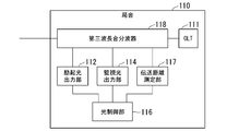
- FIG. 6 is a diagram showing a configuration of a station building 110 in the optical communication system 10 according to the second embodiment.
- the station building 110 in addition to the configuration of the optical communication system 10 according to the first embodiment, the station building 110 further includes a transmission distance measuring unit 117 and a third wavelength combiner / demultiplexer 118. It is a thing.
- the transmission distance measuring unit 117 measures the distance of the OLT optical transmission line 151 in which amplification by the excitation light occurs.
- An example of the transmission distance measuring unit 117 is an OTDR (Optical Time-Domain Reflectometer).
- the transmission distance measuring unit 117 When the transmission distance measuring unit 117 is configured by OTDR, the transmission distance measuring unit 117 outputs an optical pulse to the third wavelength duplexer 118.
- the wavelength of the optical pulse is different from the wavelength of the excitation light, the monitoring light, or the wavelength of the optical signal.
- the transmission distance measuring unit 117 acquires the scattered light and the reflected light of the optical pulse, and measures the distance of the optical transmission path based on the time series of the light receiving intensity starting from the output timing of the optical pulse.
- the third wavelength combiner / demultiplexer 118 combines the light acquired from the excitation light output unit 112, the monitoring light output unit 114, the transmission distance measurement unit 117, and the OLT 111, and outputs the light to the OLT optical transmission line 151. Further, the third wavelength combiner / demultiplexer 118 has the light acquired from the OLT optical transmission path 151 in the excitation light wavelength band, the monitoring light wavelength band, the optical signal wavelength band, and the light wavelength band output by the transmission distance measuring unit. The light is demultiplexed and output to the excitation light output unit 112, the monitoring light output unit 114, the OLT 111, and the transmission distance measurement unit 117, respectively.
- the optical transmission line distance acquisition unit 304 of the optical control unit 116 acquires the distance of the optical transmission line from the transmission distance measurement unit 117.
- FIG. 7 is a diagram showing a partial configuration of the optical amplification estimation device according to the second embodiment, and the loss of the optical transmission line at the wavelength output by the OTDR in the configuration, which is the loss observed by the OTDR. ..
- the OTDR outputs an optical pulse to the optical transmission path, and based on the intensity of the return light generated as a result of the output optical pulse and the time until it returns, the position where the loss due to reflection etc. occurs in the optical transmission path is determined. It is a device that can detect. The distance of the optical transmission line can be obtained by causing this loss at the end point of the optical transmission line.
- the wavelength output by the OTDR is demultiplexed by the second wavelength duplexer 160, and if it is terminated by the terminator 161 the loss is observed by the OTDR and the OLT.
- the distance of the optical transmission line 151 can be obtained. However, depending on the wavelength output by the OTDR, it may not be output to the terminator after being demultiplexed by the second wavelength combiner / demultiplexer 160, but may be output to the ONU optical transmission line 152 together with the optical signal. In this case, no loss is observed in the OTDR, and the distance of the OLT optical transmission line 151 cannot be obtained. Therefore, it is preferable to provide a device for demultiplexing and terminating the wavelength of the light output by the OTDR near the second wavelength combiner / demultiplexer 160.
- the fourth wavelength combiner / demultiplexer 162 demultiplexes the light transmitted by the OLT optical transmission path 151 into light having a wavelength output by the OTDR, excitation light, monitoring light, and optical signals having other wavelengths. Further, the fourth wavelength combiner / demultiplexer 162 outputs light having a wavelength output by the OTDR to the OTDR optical terminator 163. Further, light of other wavelengths is output to the second wavelength combiner / demultiplexer 160. Further, since the fourth wavelength combiner / demultiplexer 162 is installed for the purpose of measuring the distance of the OLT optical transmission line 151, it is installed near the second wavelength combiner / demultiplexer 160. The OTDR optical terminator 163 terminates the input light.
- the fourth wavelength combiner / demultiplexer 162 and the OTDR optical terminator 163 separate the light output by the OTDR from the light transmitted through the OLT optical transmission line 151 and terminate the light. As a result, in the measurement of OTDR, a loss with a large decrease in gain is detected.
- the transmission distance measuring unit 117 measures the distance of the OLT optical transmission line 151 based on the time from the irradiation start timing of the monitoring light to the timing at which the loss is detected.
- the fourth wavelength combiner / demultiplexer 162 is installed between the second wavelength combiner / demultiplexer 160 and the station building 110, but the fourth wavelength combiner / demultiplexer 162 is the second wavelength combiner / demultiplexer.
- the fourth wavelength combiner / demultiplexer installed between the second wavelength combiner / demultiplexer 160 and the ONU 130 is an optical signal and the light output by the OTDR from the light output from the second wavelength combiner / demultiplexer 160. It splits into waves.
- the optical communication system 10 may include an optical turnout instead of the fourth wavelength combiner / demultiplexer 162.
- FIG. 8 is a flowchart showing the operation of the optical amplification estimation device according to the second embodiment.
- the transmission distance measuring unit 117 measures the distance of the optical transmission line at an arbitrary timing when the uplink signal does not transmit the OLT optical transmission line 151 (step S20).
- Subsequent operations from step S21 to step S31 are the same as the operations from step S1 to step S12 in the flowchart shown in FIG. 5, except for step S27.
- the optical transmission line distance acquisition unit 304 acquires the distance of the optical transmission line measured in step S20 from the transmission distance measurement unit 117 (step S27).
- the optical communication system 10 includes a transmission distance measuring unit 117 for measuring the distance of the optical transmission line, and the optical control unit 116 is an optical transmission line measured by the transmission distance measuring unit 117. Estimate the gain of the optical signal based on the distance of. Thereby, even if the distance of the optical transmission line is not known in advance, the gain of the optical signal by Raman amplification can be estimated by measuring the distance of the optical transmission line.
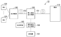
- FIG. 9 is a diagram showing the configuration of the optical communication system 10 according to the third embodiment.
- the optical communication system 10 according to the third embodiment further includes a light reflector 165 and a fifth wavelength combiner / demultiplexer 164 in addition to the configuration of the optical communication system 10 according to the first embodiment.
- the fifth wavelength combiner / demultiplexer 164 is installed between the second wavelength combiner / demultiplexer 160 and the terminator 161 and the light reflector 165 is connected to the fifth wavelength combiner / demultiplexer 164.
- the software configuration of the optical control unit 116 according to the third embodiment is different from the software configuration of the optical control unit 116 according to the first embodiment.
- the optical control unit 116 according to the third embodiment includes a reflected light measurement value acquisition unit 402 instead of the scattered light measurement value acquisition unit 302, an optical transmission line distance acquisition unit 304, and a proportional constant calculation. Does not have part 305.
- the light reflector 165 reflects the incident light in the direction opposite to the incident direction.
- the fifth wavelength combiner / demultiplexer 164 divides the light input from the second wavelength combiner / demultiplexer 160 into the excitation light and the monitoring light, and uses the light of the excitation light wavelength as the terminator and the wavelength of the monitoring light. Light is output to the light reflector 165. Further, the fifth wavelength combiner / demultiplexer 164 combines the light input from the light reflector 165 and the terminator 161 and outputs the light to the second wavelength combiner / demultiplexer 160.
- FIG. 10 is a schematic block diagram showing a software configuration of the optical control unit 116 according to the third embodiment.
- the reflected light measurement value acquisition unit 402 acquires the intensity value of the reflected light detected by the monitoring light output unit 114.
- the intensity of the reflected light of the monitoring light is significantly higher than the intensity of the scattered light of the monitoring light. Therefore, the incident light detection unit 203 of the monitoring light output unit 114 can identify that the light is the reflected light when the light stronger than the predetermined intensity is detected.
- the monitoring light wavelength band gain calculation unit 307 calculates G2 based on the intensity value of the reflected light acquired by the reflected light measurement value acquisition unit 402.
- the monitoring light on / off unit 301, the excitation light on / off unit 303, the gain ratio acquisition unit 308, the optical signal gain calculation unit 309, and the output unit 310 are the monitoring light on / off units of the optical control unit 116 according to the first embodiment, respectively. It is the same as 301, the excitation light on / off unit 303, the gain ratio acquisition unit 308, the optical signal gain calculation unit 309, and the output unit 310.
- the gain G2 to be calculated by the optical signal gain calculation unit 309 is a gain received when the monitoring light is transmitted by the same path as the uplink signal.
- the gain received when transmitting is calculated.
- the gain of amplification by excitation light changes depending on the polarization state of the excitation light and the polarization state of the light to be amplified.
- the gain received when the monitoring light is transmitted back and forth differs between the outward path and the return path.
- the gain received when the monitoring light is transmitted on the same path as the uplink signal can be easily estimated. For example, if the polarization state of the excitation light is a random polarization state, the gains of the outward path and the return path can be made equal.
- the finally obtained gain G3 is the gain received when the optical signal is transmitted one-way through the OLT optical transmission line 151.
- the monitoring light reciprocates in the OLT optical transmission line 151 and receives twice the gain as in the case of one-way transmission. Therefore, in equation (4), when calculating G2, it is necessary to multiply the value obtained by dividing RON by R OFF by half.
- the calculation method of G3 is the same as the calculation method of G3 according to the first embodiment.
- FIG. 11 is a flowchart showing the operation of the optical amplification estimation device according to the third embodiment.
- the monitoring light on / off unit 301 outputs a monitoring light output instruction to the monitoring light output unit 114.
- the monitoring light output unit 114 acquires an output instruction and outputs the monitoring light to the first wavelength combiner / demultiplexer 113 (step S41).
- the excitation light on / off unit 303 outputs an instruction to stop the output of the excitation light to the excitation light output unit 112.
- the excitation light output unit 112 acquires an output stop instruction and stops the output of the excitation light to the first wavelength combiner / demultiplexer 113 (step S42).
- the monitoring light is reflected by the light reflector 165, and the reflected light is incident on the monitoring light output unit 114.
- the monitoring light output unit 114 detects this reflected light and measures its intensity.
- the reflected light measurement value acquisition unit 402 acquires the data of this intensity (step S43).
- the excitation light on / off unit 303 After acquiring the reflected light intensity data, the excitation light on / off unit 303 outputs an excitation light output instruction to the excitation light output unit 112.
- the excitation light output unit 112 acquires an output instruction and outputs the excitation light to the first wavelength combiner / demultiplexer 113 (step S44).
- the reflected light is incident on the monitoring light output unit 114 as in the case where the excitation light is not incident.
- the monitoring light and its reflected light are amplified by the excitation light.
- the monitoring light output unit 114 detects this reflected light and measures its intensity.
- the reflected light measurement value acquisition unit 402 acquires the data of this intensity (step S45).
- the monitoring light wavelength band gain calculation unit 307 calculates G2 based on the intensity value of the reflected light acquired by the reflected light measurement value acquisition unit 402 (step S46).
- the wavelength dependence acquisition unit 408 acquires wavelength and gain dependency data (step S47).
- the optical signal gain calculation unit 309 calculates G3 based on G2 and the wavelength and gain dependency data (step S48).
- the output unit 310 outputs the value of G3 (step S49), and ends the process.
- the optical communication system 10 includes a light reflector 165, and the light reflector 165 reflects the monitoring light output from the monitoring light output unit 114. After that, the monitoring light output unit detects the reflected light, the optical control unit 116 calculates the gain G2, and the optical control unit 116 calculates the gain G3 of the uplink signal based on the value of G2. This makes it possible to estimate the gain of the optical signal by Raman amplification even when the scattered light is weak and measurement is difficult.
- the optical amplification estimation device is equipped with a CPU (Central Processing Unit) connected by a bus, a memory, an auxiliary storage device, etc., and by executing a program, a monitoring light on / off section, a scattered light measurement value acquisition section, and an excitation light on / off section are provided. It functions as a device including a unit, an optical transmission path distance acquisition unit, a proportional constant calculation unit, a scattered light gain calculation unit, a monitoring light wavelength band gain calculation unit, a gain ratio acquisition unit, an optical signal gain calculation unit, and an output unit.
- a CPU Central Processing Unit
- All or part of each function of the optical amplification estimation device may be realized by using hardware such as ASIC (Application Specific Integrated Circuit), PLD (Programmable Logic Device), and FPGA (Field Programmable Gate Array). ..
- the program may be recorded on a computer-readable recording medium.
- the computer-readable recording medium is, for example, a flexible disk, a magneto-optical disk, a portable medium such as a ROM or a CD-ROM, or a storage device such as a hard disk built in a computer system.
- the program may be transmitted over a telecommunication line.
- Optical communication system 110 910 Station building 111, 911 OLT 112, 912 Excitation light output unit 113 First wavelength combiner / demultiplexer 114 Monitoring light output unit 116 Optical control unit 117 Transmission distance measurement unit 118 Third wavelength combiner / demultiplexer 130, 930 ONU 140, 940 Optical branching device 151, 951 OLT Optical transmission line 152, 952 ONU Optical transmission line 160 Second wavelength duplexer 161, 961 Terrier 162 Fourth wavelength duplexer 163 OTDR Optical terminator 164 Fifth wavelength Combined demultiplexer 165 Optical reflector 201 Light source 202 Isolator 203 Incident light detector 204 Optical fiber coupler 301 Monitoring light on / off part 302 Scattered light measurement value acquisition part 303 Excitation light on / off part 304 Optical transmission path distance acquisition part 305 Proportional constant Calculation unit 306 Scattered light gain calculation unit 307 Monitoring light wavelength band gain calculation unit 308 Gain ratio acquisition unit 309
Landscapes
- Engineering & Computer Science (AREA)
- Computer Networks & Wireless Communication (AREA)
- Signal Processing (AREA)
- Physics & Mathematics (AREA)
- Electromagnetism (AREA)
- Optical Communication System (AREA)
Abstract
Procédé d'estimation d'amplification optique comprenant : une étape d'entrée de lumière d'excitation dans laquelle une unité de sortie de lumière d'excitation connectée à un premier terminal d'un premier trajet de transmission optique amène une lumière d'excitation à entrer dans le premier trajet de transmission optique ; une étape d'entrée de lumière de surveillance dans laquelle une unité de surveillance connectée au même côté que le premier terminal du premier trajet de transmission optique amène une lumière de surveillance ayant une longueur d'onde différente de celle de la lumière d'excitation à entrer dans le premier trajet de transmission optique ; une étape de mesure de lumière entrée dans laquelle l'unité de surveillance mesure l'intensité de la lumière qui entre dans l'unité de surveillance lorsque la lumière d'excitation a été amenée à entrer, et l'intensité de la lumière qui entre dans l'unité de surveillance lorsque la lumière d'excitation n'a pas été amenée à entrer ; et une étape d'estimation d'amplification dans laquelle une unité d'estimation d'amplification estime le gain d'un signal optique dans le premier trajet de transmission optique sur la base des intensités de lumière mesurées dans l'étape de mesure de lumière entrée. Une partie du premier trajet de transmission optique est partagée avec un second trajet de transmission optique qui est utilisé par une unité de réseau optique (ONU) et un terminal de ligne optique (OLT) pour émettre et recevoir des signaux optiques.
Priority Applications (3)
| Application Number | Priority Date | Filing Date | Title |
|---|---|---|---|
| PCT/JP2020/021142 WO2021240730A1 (fr) | 2020-05-28 | 2020-05-28 | Procédé d'estimation d'amplification optique, dispositif d'estimation d'amplification optique et programme informatique |
| US17/927,056 US12119869B2 (en) | 2020-05-28 | 2020-05-28 | Optical amplification estimation method, optical amplification estimation apparatus and computer program |
| JP2022527398A JP7492155B2 (ja) | 2020-05-28 | 2020-05-28 | 光増幅推定方法、光増幅推定装置、およびコンピュータプログラム |
Applications Claiming Priority (1)
| Application Number | Priority Date | Filing Date | Title |
|---|---|---|---|
| PCT/JP2020/021142 WO2021240730A1 (fr) | 2020-05-28 | 2020-05-28 | Procédé d'estimation d'amplification optique, dispositif d'estimation d'amplification optique et programme informatique |
Publications (1)
| Publication Number | Publication Date |
|---|---|
| WO2021240730A1 true WO2021240730A1 (fr) | 2021-12-02 |
Family
ID=78723137
Family Applications (1)
| Application Number | Title | Priority Date | Filing Date |
|---|---|---|---|
| PCT/JP2020/021142 Ceased WO2021240730A1 (fr) | 2020-05-28 | 2020-05-28 | Procédé d'estimation d'amplification optique, dispositif d'estimation d'amplification optique et programme informatique |
Country Status (3)
| Country | Link |
|---|---|
| US (1) | US12119869B2 (fr) |
| JP (1) | JP7492155B2 (fr) |
| WO (1) | WO2021240730A1 (fr) |
Citations (7)
| Publication number | Priority date | Publication date | Assignee | Title |
|---|---|---|---|---|
| JP2002296145A (ja) * | 2001-04-02 | 2002-10-09 | Nec Corp | 光ファイバ伝送路のラマン利得及びラマン利得効率測定方法及び利得効率測定装置 |
| JP2003139656A (ja) * | 2001-10-31 | 2003-05-14 | Nec Corp | 光ファイバ伝送システム、ラマン利得効率測定装置及びラマン利得効率測定方法 |
| JP2011059424A (ja) * | 2009-09-10 | 2011-03-24 | Fujitsu Ltd | 光伝送装置、光伝送システムおよび光伝送方法 |
| JP2013183231A (ja) * | 2012-02-29 | 2013-09-12 | Fujitsu Optical Components Ltd | 伝送装置および伝送方法 |
| US20160072576A1 (en) * | 2014-09-04 | 2016-03-10 | Ciena Corporation | Live monitoring of raman and fiber degradation in dwdm networks using in-service otdr |
| WO2017141423A1 (fr) * | 2016-02-19 | 2017-08-24 | 三菱電機株式会社 | Appareil de source de lumière d'excitation et système de transmission optique |
| US9762319B1 (en) * | 2015-09-29 | 2017-09-12 | Juniper Networks, Inc. | Real-time Raman gain monitoring |
Family Cites Families (1)
| Publication number | Priority date | Publication date | Assignee | Title |
|---|---|---|---|---|
| US8571410B2 (en) * | 2006-10-11 | 2013-10-29 | Novera Optics, Inc. | Mutual wavelength locking in WDM-PONS |
-
2020
- 2020-05-28 US US17/927,056 patent/US12119869B2/en active Active
- 2020-05-28 WO PCT/JP2020/021142 patent/WO2021240730A1/fr not_active Ceased
- 2020-05-28 JP JP2022527398A patent/JP7492155B2/ja active Active
Patent Citations (7)
| Publication number | Priority date | Publication date | Assignee | Title |
|---|---|---|---|---|
| JP2002296145A (ja) * | 2001-04-02 | 2002-10-09 | Nec Corp | 光ファイバ伝送路のラマン利得及びラマン利得効率測定方法及び利得効率測定装置 |
| JP2003139656A (ja) * | 2001-10-31 | 2003-05-14 | Nec Corp | 光ファイバ伝送システム、ラマン利得効率測定装置及びラマン利得効率測定方法 |
| JP2011059424A (ja) * | 2009-09-10 | 2011-03-24 | Fujitsu Ltd | 光伝送装置、光伝送システムおよび光伝送方法 |
| JP2013183231A (ja) * | 2012-02-29 | 2013-09-12 | Fujitsu Optical Components Ltd | 伝送装置および伝送方法 |
| US20160072576A1 (en) * | 2014-09-04 | 2016-03-10 | Ciena Corporation | Live monitoring of raman and fiber degradation in dwdm networks using in-service otdr |
| US9762319B1 (en) * | 2015-09-29 | 2017-09-12 | Juniper Networks, Inc. | Real-time Raman gain monitoring |
| WO2017141423A1 (fr) * | 2016-02-19 | 2017-08-24 | 三菱電機株式会社 | Appareil de source de lumière d'excitation et système de transmission optique |
Also Published As
| Publication number | Publication date |
|---|---|
| JP7492155B2 (ja) | 2024-05-29 |
| JPWO2021240730A1 (fr) | 2021-12-02 |
| US20230224034A1 (en) | 2023-07-13 |
| US12119869B2 (en) | 2024-10-15 |
Similar Documents
| Publication | Publication Date | Title |
|---|---|---|
| US11201667B2 (en) | Optical fiber characterization measurement systems and methods | |
| US8175454B2 (en) | Fault locator for long haul transmission system | |
| JP7597574B2 (ja) | 時分割及び空間分割多重化に基づく中継海底光ファイバケーブル振動監視システム | |
| US11169019B2 (en) | Distributed fiber optic acoustic sensor | |
| JP4782644B2 (ja) | 光通信システムを監視するシステム及び方法 | |
| US9503181B2 (en) | Rare earth-doped fiber amplifier with integral optical metrology functionality | |
| US20180019813A1 (en) | Raman amplifier system and method with integrated optical time domain reflectometer | |
| US20190003879A1 (en) | Improved optical fiber sensing system | |
| US9948058B2 (en) | Method and apparatus for determining optical fibre characteristics | |
| JP4847467B2 (ja) | 光学システム | |
| JP4671842B2 (ja) | 光ファイバセンサ装置 | |
| EP1182806A2 (fr) | Système de contrôle d'une voie de transmission optique | |
| JP2022104520A (ja) | 海底ケーブルにおけるdas範囲のループバックによる拡張 | |
| JP2025502381A (ja) | 全ラマン増幅および符号化方式を使用した、繰り返しファイバスパンを介した長距離の分散型光ファイバセンシング(dfos)およびwdm通信 | |
| JP2023527128A (ja) | マルチスパンファイバリンク上の分散型音響検知のための中継器設計 | |
| US20040208503A1 (en) | Systems and methods for detecting faults in optical communication systems | |
| US7769291B2 (en) | Optical communication network and component therefore | |
| US6337936B1 (en) | Optical amplifier, and method and apparatus for monitoring an optical fiber transmission path | |
| WO2021240730A1 (fr) | Procédé d'estimation d'amplification optique, dispositif d'estimation d'amplification optique et programme informatique | |
| US11462882B2 (en) | Distributed Raman amplifier systems | |
| US20050196175A1 (en) | Method and apparatus for obtaining status information concerning an in-service optical transmission line | |
| JP2007518365A (ja) | Cotdrを用いた稼動中の局所的な海底光学伝達装置のモニタのための方法および装置 | |
| JP3487253B2 (ja) | 光伝送路監視システム及び光伝送路監視方法 | |
| CA3089139C (fr) | Systemes et procedes de mesure pour caracterisation de fibre optique | |
| JP6817234B2 (ja) | 光送受信器 |
Legal Events
| Date | Code | Title | Description |
|---|---|---|---|
| 121 | Ep: the epo has been informed by wipo that ep was designated in this application |
Ref document number: 20937911 Country of ref document: EP Kind code of ref document: A1 |
|
| ENP | Entry into the national phase |
Ref document number: 2022527398 Country of ref document: JP Kind code of ref document: A |
|
| NENP | Non-entry into the national phase |
Ref country code: DE |
|
| 122 | Ep: pct application non-entry in european phase |
Ref document number: 20937911 Country of ref document: EP Kind code of ref document: A1 |