WO2021241237A1 - Dispositif anti-vibration, dispositif optique, jumelles, procédé de commande pour dispositif anti-vibration, et programme - Google Patents
Dispositif anti-vibration, dispositif optique, jumelles, procédé de commande pour dispositif anti-vibration, et programme Download PDFInfo
- Publication number
- WO2021241237A1 WO2021241237A1 PCT/JP2021/018102 JP2021018102W WO2021241237A1 WO 2021241237 A1 WO2021241237 A1 WO 2021241237A1 JP 2021018102 W JP2021018102 W JP 2021018102W WO 2021241237 A1 WO2021241237 A1 WO 2021241237A1
- Authority
- WO
- WIPO (PCT)
- Prior art keywords
- vibration
- correction unit
- frequency band
- detector
- value
- Prior art date
- Legal status (The legal status is an assumption and is not a legal conclusion. Google has not performed a legal analysis and makes no representation as to the accuracy of the status listed.)
- Ceased
Links
Images


Classifications
-
- H—ELECTRICITY
- H04—ELECTRIC COMMUNICATION TECHNIQUE
- H04N—PICTORIAL COMMUNICATION, e.g. TELEVISION
- H04N23/00—Cameras or camera modules comprising electronic image sensors; Control thereof
- H04N23/60—Control of cameras or camera modules
- H04N23/68—Control of cameras or camera modules for stable pick-up of the scene, e.g. compensating for camera body vibrations
- H04N23/681—Motion detection
- H04N23/6812—Motion detection based on additional sensors, e.g. acceleration sensors
-
- G—PHYSICS
- G02—OPTICS
- G02B—OPTICAL ELEMENTS, SYSTEMS OR APPARATUS
- G02B27/00—Optical systems or apparatus not provided for by any of the groups G02B1/00 - G02B26/00, G02B30/00
- G02B27/64—Imaging systems using optical elements for stabilisation of the lateral and angular position of the image
- G02B27/646—Imaging systems using optical elements for stabilisation of the lateral and angular position of the image compensating for small deviations, e.g. due to vibration or shake
-
- G—PHYSICS
- G03—PHOTOGRAPHY; CINEMATOGRAPHY; ANALOGOUS TECHNIQUES USING WAVES OTHER THAN OPTICAL WAVES; ELECTROGRAPHY; HOLOGRAPHY
- G03B—APPARATUS OR ARRANGEMENTS FOR TAKING PHOTOGRAPHS OR FOR PROJECTING OR VIEWING THEM; APPARATUS OR ARRANGEMENTS EMPLOYING ANALOGOUS TECHNIQUES USING WAVES OTHER THAN OPTICAL WAVES; ACCESSORIES THEREFOR
- G03B5/00—Adjustment of optical system relative to image or object surface other than for focusing
-
- H—ELECTRICITY
- H04—ELECTRIC COMMUNICATION TECHNIQUE
- H04N—PICTORIAL COMMUNICATION, e.g. TELEVISION
- H04N23/00—Cameras or camera modules comprising electronic image sensors; Control thereof
- H04N23/60—Control of cameras or camera modules
- H04N23/68—Control of cameras or camera modules for stable pick-up of the scene, e.g. compensating for camera body vibrations
- H04N23/682—Vibration or motion blur correction
- H04N23/683—Vibration or motion blur correction performed by a processor, e.g. controlling the readout of an image memory
-
- G—PHYSICS
- G02—OPTICS
- G02B—OPTICAL ELEMENTS, SYSTEMS OR APPARATUS
- G02B23/00—Telescopes, e.g. binoculars; Periscopes; Instruments for viewing the inside of hollow bodies; Viewfinders; Optical aiming or sighting devices
- G02B23/16—Housings; Caps; Mountings; Supports, e.g. with counterweight
- G02B23/18—Housings; Caps; Mountings; Supports, e.g. with counterweight for binocular arrangements
-
- G—PHYSICS
- G03—PHOTOGRAPHY; CINEMATOGRAPHY; ANALOGOUS TECHNIQUES USING WAVES OTHER THAN OPTICAL WAVES; ELECTROGRAPHY; HOLOGRAPHY
- G03B—APPARATUS OR ARRANGEMENTS FOR TAKING PHOTOGRAPHS OR FOR PROJECTING OR VIEWING THEM; APPARATUS OR ARRANGEMENTS EMPLOYING ANALOGOUS TECHNIQUES USING WAVES OTHER THAN OPTICAL WAVES; ACCESSORIES THEREFOR
- G03B2205/00—Adjustment of optical system relative to image or object surface other than for focusing
- G03B2205/0007—Movement of one or more optical elements for control of motion blur
Definitions
- the technology of the present disclosure relates to an anti-vibration device, an optical device, binoculars, a control method for the anti-vibration device, and a program.
- Japanese Patent Application Laid-Open No. 2009-55568 performs image shake correction for canceling image shake caused by vibration applied to the photographing optical system based on a sensor signal output from a shake detection sensor for detecting image shake.
- An image shake correction device for a camera provided with an image shake correction means is disclosed.
- the image shake correction device of the camera includes a vibration signal acquisition means for acquiring a vibration signal from an external device, a noise removing means for removing noise of the vibration signal acquired by the vibration signal acquisition means, and a vibration signal acquisition means when there is no vibration.
- a setting means for setting the frequency of a signal component to be removed as noise by the noise removing means based on the vibration signal acquired by the image shake correction means is provided, and the image shake correction means is a vibration signal acquisition means instead of the sensor signal of the shake detection sensor.
- image shake correction is performed based on the vibration signal acquired by the vibration signal acquisition means
- image shake correction is performed based on the vibration signal acquired by the vibration signal acquisition means after the setting by the setting means is completed.
- Japanese Patent Application Laid-Open No. 2009-38515 is a vibration isolation device for a camera device capable of a turning operation of rotating around a predetermined axis to change the shooting direction, and the imaging direction of the camera device from the center of rotation.
- the first vibration detecting means provided on the side
- the second vibration detecting means provided on the opposite side of the image pickup direction of the camera device from the center of rotation
- the vibration correction for correcting the vibration of the image pickup due to the vibration are performed.
- the vibration compensating means the determining means for determining whether or not the turning operation is in progress using the vibration information detected by the first vibration detecting means and the vibration information detected by the second vibration detecting means, and the determining means.
- a vibration isolator comprising: a control means for controlling the vibration compensating means so as not to execute the vibration compensating when it is determined to be.
- One embodiment according to the technique of the present disclosure can realize vibration isolation according to the usage status of the vibration isolation device, as compared with the case where the second vibration detector arranged other than the vibration correction unit is not provided.
- a control method and a program for a vibration device, an optical device, binoculars, and a vibration isolation device are provided.
- the first aspect according to the technique of the present disclosure is a vibration isolator having a vibration correction unit, the first vibration detector arranged in the vibration correction unit and the second vibration detection arranged in other than the vibration correction unit.
- a device and a processor are provided, and the processor performs vibration isolation control based on a first output value output from the first vibration detector and a second output value output from the second vibration detector. It is a device.
- the second aspect according to the technique of the present disclosure is the anti-vibration device according to the first aspect, in which the anti-vibration device is an integrated device.
- a third aspect according to the technique of the present disclosure is the first aspect or the second aspect in which the vibration detection axes of the first vibration detector and the second vibration detector are parallel to the rotation axis of the vibration correction unit.
- This is a vibration isolation device.
- the runout correction unit has a plurality of rotation axes, and the vibration detection shaft and the vibration detection shaft are used in the axial directions of the vibration detection shafts of the first vibration detector and the second vibration detector. It is a vibration isolator according to the third aspect in which the rotation axis is parallel to the rotation axis.
- a fifth aspect according to the technique of the present disclosure is the prevention according to any one of the first to fourth aspects, wherein the second vibration detector has a lower sensitivity than the first vibration detector. It is a vibration device.
- a sixth aspect according to the technique of the present disclosure is that the second vibration detector has the same sensitivity as the first vibration detector, and the prevention according to any one of the first to fourth aspects. It is a vibration device.
- a seventh aspect according to the technique of the present disclosure is the first to sixth aspects in which the frequency band detectable by the second vibration detector is wider than the frequency band detectable by the first vibration detector. It is a vibration isolator according to any one of the above embodiments.
- Eighth aspect according to the technique of the present disclosure is the first to sixth aspects in which the frequency band detectable by the second vibration detector is equivalent to the frequency band detectable by the first vibration detector. It is a vibration isolator according to any one of the embodiments.
- a ninth aspect according to the technique of the present disclosure is any one of the first to eighth aspects in which the processor controls the first output value to approach a predetermined value in vibration isolation control. This is the anti-vibration device.
- a tenth aspect according to the technique of the present disclosure is a tenth aspect from the first aspect to the ninth aspect in which the processor detects the usage status of the anti-vibration device based on the second output value and performs the anti-vibration control based on the detection result. It is a vibration isolation device which concerns on any one aspect of.
- the eleventh aspect according to the technique of the present disclosure is the anti-vibration device according to the tenth aspect including the situation in which the usage state is caused by the usage environment of the anti-vibration device.
- the twelfth aspect according to the technique of the present disclosure is the vibration isolator according to the tenth aspect, in which the usage state is at least one of the start and end of the turning operation of the vibration isolator.
- a thirteenth aspect according to the technique of the present disclosure is a vibration isolator according to a twelfth aspect in which the turning operation is at least one of a panning operation and a tilting operation.
- the detectable frequency band of the first vibration detector can be changed, and the processor sets the detectable frequency band to a wide frequency band when the vibration correction unit performs the vibration isolation operation.
- the vibration isolation according to the twelfth aspect or the thirteenth aspect, wherein when the processor detects the start of the turning operation, the detectable frequency band is changed to a narrow frequency band having a narrower bandwidth than the wide frequency band. It is a device.
- a fifteenth aspect according to the technique of the present disclosure is the vibration isolator according to the fourteenth aspect, wherein the processor changes the detectable frequency band from the narrow frequency band to the wide frequency band when the processor detects the end of the turning operation. ..
- the sixteenth aspect according to the technique of the present disclosure is the twelfth aspect to the fourteenth aspect in which the lower limit of the detectable frequency band of the first vibration detector is changed to the high frequency side when the processor detects the end of the turning operation. It is a vibration isolator according to any one of the embodiments.
- the processor measures the frequency of vibration given to the vibration isolator based on the second output value, and sets the detectable frequency band to the high frequency side according to the measured frequency.
- the anti-vibration device according to any one of the fourteenth to sixteenth aspects, which is widened to at least one of the low frequency side.
- An eighteenth aspect of the technique of the present disclosure is that the processor stores at least one of the amplitudes and frequencies of vibration contained in the second output value in memory and at least one of the amplitudes and frequencies stored in the memory. Based on one of the above, the vibration isolator according to any one of the first to the seventeenth aspects, which determines the control content of the vibration isolation control at the time of starting the vibration isolation device.
- a nineteenth aspect according to the technique of the present disclosure is that the processor predicts the displacement of the runout correction unit from the reference position by integrating the second output value, and when the predicted value of the displacement exceeds the predetermined range, the runout is predicted.
- the vibration isolator according to any one of the first to eighteenth aspects, in which the correction unit is controlled to be fixed at the reference position.
- a twentieth aspect according to the technique of the present disclosure comprises a housing in which a runout correction unit is housed, and a second vibration detector is one of the first to nineteenth aspects arranged in the housing. It is a vibration isolator according to any one of the items.
- the 21st aspect according to the technique of the present disclosure is the anti-vibration device according to the 20th aspect, which is a device integrated by a housing.
- a 22nd aspect according to the technique of the present disclosure is an optical device including a vibration isolator according to any one of the 1st to 21st aspects and one or more observation optical systems. ..
- a 23rd aspect according to the technique of the present disclosure is that the optical device according to the 22nd aspect is binoculars including two observation optical systems, and the first vibration detector is arranged at the center of the two observation optical systems. Binoculars.
- the 24th aspect according to the technique of the present disclosure is the binoculars according to the 23rd aspect in which the second vibration detector is attached to an object holding the vibration correction unit.
- the 25th aspect according to the technique of the present disclosure is the binoculars according to the 24th aspect, in which the object is a frame holding a shake correction unit or a housing of binoculars.
- a twenty-sixth aspect according to the technique of the present disclosure is a prevention including a runout correction unit, a first vibration detector arranged in the runout correction unit, and a second vibration detector arranged in a position other than the runout correction unit.
- a method for controlling a vibration device which includes performing vibration isolation control based on a first output value output from the first vibration detector and a second output value output from the second vibration detector. This is a control method for the vibration device.
- a 27th aspect according to the technique of the present disclosure is a prevention including a runout correction unit, a first vibration detector arranged in the runout correction unit, and a second vibration detector arranged in a position other than the runout correction unit.
- the computer applied to the vibration device is subjected to vibration isolation control based on the first output value output from the first vibration detector and the second output value output from the second vibration detector. It is a program for executing the including processing.
- CPU is an abbreviation for "Central Processing Unit”.
- RAM is an abbreviation for "RandomAccessMemory”.
- EEPROM refers to the abbreviation of "Electrically Erasable Programmable Read-Only Memory”.
- SSD is an abbreviation for "Solid State Drive”.
- ASIC is an abbreviation for "Application Specific Integrated Circuit”.
- PLD is an abbreviation for "Programmable Logic Device”.
- FPGA refers to the abbreviation of "Field-Programmable Gate Array”.
- SoC is an abbreviation for "System-on-a-chip”.
- USB is an abbreviation for "Universal Serial Bus”.
- HDD is an abbreviation for "Hard Disk Drive”.
- HPF is an abbreviation for "High-Pass Filter”.
- LPF is an abbreviation for "Low-Pass Filter”.
- IC refers to the abbreviation of "Integrated Circuit”.
- DRAM is an abbreviation for "Dynamic Random Access Memory”.
- SRAM is an abbreviation for "Static Random Access Memory”.
- parallel means, in addition to perfect parallelism, an error generally allowed in the technical field to which the technique of the present disclosure belongs, to the extent that it does not contradict the purpose of the technique of the present disclosure. Refers to parallelism in the sense including the error of.
- match is an error generally allowed in the technical field to which the technique of the present disclosure belongs, in addition to the perfect match, which is contrary to the purpose of the technique of the present disclosure. It refers to a match in the sense that includes an error that does not occur.
- “equivalent” is an error generally allowed in the technical field to which the technology of the present disclosure belongs, in addition to the perfect equivalence, and is contrary to the purpose of the technology of the present disclosure. It refers to the equivalent in the sense that it includes an error to the extent that it does not occur.
- “constant” is an error generally allowed in the technical field to which the technology of the present disclosure belongs, in addition to being completely constant, which is contrary to the purpose of the technology of the present disclosure. It refers to a certain level of meaning including an error that does not occur.
- the binoculars 10 are provided with a substantially rectangular housing 11, a pair of objective lens units 12R and 12L provided in front of the housing 11, and rear of the housing 11. Includes a pair of eyepiece units 13R and 13L.
- the width direction of the binoculars 10 is the X direction
- the front-back direction of the binoculars 10 is the Y direction
- the vertical direction of the binoculars 10 is the Z direction.
- the direction toward the observation target in the binoculars 10, that is, the direction in which the objective lens units 12R and 12L are arranged is defined as the front.
- the direction in which the user of the binoculars 10 (hereinafter, simply referred to as “user”) is located, that is, the direction in which the eyepiece units 13R and 13L are arranged is defined as the rear.
- the optical system for generating an image observed by the user's right eye is called an optical system for the right eye
- the optical system for generating an image observed by the user's left eye is called an optical system for the left eye.
- the binoculars 10 are examples of “binoculars” and “optical devices” according to the technique of the present disclosure.
- the right-eye optical system and the left-eye optical system are examples of "one or more observation optical systems” and "two observation optical systems” according to the technique of the present disclosure. In the following, for convenience of explanation, when it is not necessary to distinguish between the optical system for the right eye and the optical system for the left eye, these are simply referred to as “optical systems”.
- the objective lens unit 12R and the eyepiece unit 13R are arranged along the Y direction and form a part of the optical system for the right eye.
- the objective lens unit 12L and the eyepiece lens unit 13L are arranged along the Y direction and form a part of the left eye optical system.
- a push button type power switch 15 is provided on the rear surface of the housing 11. By pressing the power switch 15, the power of the binoculars 10 can be switched on and off.
- a slide-type anti-vibration switch 16 is provided on the upper surface of the housing 11. By sliding the anti-vibration switch 16 backward, the anti-vibration operation (hereinafter, also simply referred to as “vibration-proof operation”) by the vibration correction unit 30 (see FIGS. 2 and 3) described later is started. By sliding the anti-vibration switch 16 forward, the anti-vibration operation is stopped.
- the housing 11 includes a runout correction unit 30.
- the shake correction unit 30 includes a mechanism for preventing image shake caused by vibration given to the binoculars 10 (hereinafter, also simply referred to as “vibration”). Examples of the vibration include vibration caused by camera shake of a user holding the binoculars 10, and vibration caused by shaking of a vehicle (for example, a vehicle or a ship).
- the "image” refers to, for example, an optical image formed by incident observation target light indicating an observation target onto an optical system.
- the shake correction unit 30 is arranged between the objective lens units 12R and 12L and the eyepiece lens units 13R and 13L in the Y direction.
- the runout correction unit 30 is an example of the "shake correction unit” according to the technique of the present disclosure
- the housing 11 is an example of the "housing" according to the technique of the present disclosure.
- Each of the eyepiece units 13R and 13L has an eyepiece 20, an eyepiece 21 for holding the eyepiece 20, and a prism holder 22 connected to the eyepiece 21.
- the bending prism 23 is housed in the prism holder 22.
- the bending prism 23 translates the optical axis by bending the incident light.
- the optical axis BL for the left eye is translated in the Z-axis direction by the bending prism 23.
- Each of the objective lens units 12R and 12L has an objective lens 26 and an objective cylinder 27 for holding the objective lens 26.
- each of the eyepiece 20 and the objective lens 26 is drawn as one lens, but in reality, each of the eyepiece 20 and the objective lens 26 has a plurality of lenses. It is a lens group including.
- the runout correction unit 30 houses the correction optical elements 31R and 31L.
- the correction optical elements 31R and 31L are, for example, roof prism type erecting prisms, and the inverted image formed by the objective lens 26 and the eyepiece lens 20 is returned to the erecting image.
- a poro prism type erecting prism may be used, or an erecting lens may be used instead of the erecting prism.
- the right eye optical system includes an objective lens 26, a correction optical element 31R, and a bending prism 23.
- the objective lens 26, the correction optical element 31R, and the bending prism 23 are arranged in this order from the observation target side along the optical axis BR for the right eye in the order of the objective lens 26, the correction optical element 31R, and the bending prism 23.
- the left eye optical system includes an objective lens 26, a correction optical element 31L, and a bending prism 23.
- the objective lens 26, the correction optical element 31L, and the bending prism 23 are arranged in this order from the observation target side along the optical axis BL for the left eye in the order of the objective lens 26, the correction optical element 31L, and the bending prism 23.
- the light to be observed is incident on the eyepiece 20 via the optical system for the right eye and the optical system for the left eye.
- the user can observe the observation target as if the magnified observation target is in front of the eyes by viewing the observation target through the optical system for the right eye and the optical system for the left eye.
- the runout correction unit 30 has, for example, a gimbal structure.
- the runout correction unit 30 includes a first holder 32 and a second holder 33.
- the first holder 32 holds the correction optical elements 31R and 31L.
- the second holder 33 holds the first holder 32.
- the first holder 32 has a rectangular parallelepiped shape and is arranged along the X direction in the longitudinal direction.
- the runout correction unit 30 has a plurality of rotation axes.
- the rotation shafts of the runout correction unit 30 are rotation shafts 28 and 29.
- the first holder 32 is supported by a rotation shaft 29 provided on the second holder 33 along the Z direction, and is rotatable about the rotation shaft 29 in the direction of the arrow RA around the Z axis.
- the second holder 33 has a rectangular parallelepiped shape larger than that of the first holder 32, and is arranged along the X direction in the longitudinal direction.
- the second holder 33 When the second holder 33 is in the posture shown in FIG. 4, the second holder 33 has a frame shape having a surface parallel to the optical axis BR for the right eye and the optical axis BL for the left eye, and is formed by the second holder 33.
- the first holder 32 is rotatably housed inside.
- the second holder 33 is supported by a rotation shaft 28 provided along the X direction, and is rotatable in the direction of the arrow RE around the X axis.
- the rotating shaft 28 is supported by a pair of bearing portions 45R and 45L provided on the housing 11.
- the rotating shafts 28 and 29 are examples of the "rotating shaft" according to the technique of the present disclosure.
- the first holder 32 has an element accommodating portion 34R on the optical axis BR for the right eye and an element accommodating portion 34L on the optical axis BL for the left eye.
- the element accommodating portion 34R accommodates the correction optical element 31R
- the element accommodating portion 34L accommodates the correction optical element 31L.
- An opening 35R is provided on the front surface and the rear surface of the first holder 32. The opening 35R exposes the correction optical element 31R from the element accommodating portion 34R on the optical axis BR for the right eye.
- an opening 35L is provided on the front surface and the rear surface of the first holder 32. The opening 35L exposes the correction optical element 31L from the element accommodating portion 34L on the optical axis BL for the left eye.
- the vibration correction unit 30 When vibration is applied to the housing 11 due to the influence of camera shake of the user holding the binoculars 10, this vibration causes vibration in the image observed by the binoculars 10.
- the vibration correction unit 30 having a gimbal structure exerts an inertial force corresponding to the vibration applied to the housing 11, the correction optical element 31R has a correction optical element 31R as compared with the case where it does not have a vibration isolation structure such as a gimbal structure. And vibration is hard to be transmitted to 31L.
- relative displacement occurs between the correction optical elements 31R and 31L, the objective lens units 12R and 12L, and the eyepiece lens units 13R and 13L, so that the case does not have a vibration-proof structure such as a gimbal structure. , The observed image shake is reduced.
- the runout correction unit 30 includes a first gyro sensor 39 that detects the angular velocity due to the rotation of the runout correction unit 30. Further, as shown in FIG. 4, as an example, the runout correction unit 30 includes a runout correction motor 40 driven based on the detection result of the first gyro sensor 39.
- the first gyro sensor 39 is arranged in the runout correction unit 30. More specifically, the first gyro sensor 39 is arranged at the center of the right eye optical system and the left eye optical system. The first gyro sensor 39 detects the angular velocity due to the rotation of the runout correction unit 30 and outputs it as a first angular velocity signal (see FIGS. 9 and 10).
- the first gyro sensor 39 is an example of the "first vibration detector" according to the technique of the present disclosure.
- the first gyro sensor 39 includes an X-axis gyro sensor 38 and a Z-axis gyro sensor 37 (see FIG. 3).
- the X-axis gyro sensor 38 is attached to the upper surface of the inner wall of the second holder 33.
- the X-axis gyro sensor 38 is the angular velocity of the second holder 33 that rotates around the vibration detection shaft 38A parallel to the X-axis, that is. , Detects the angular velocity around the X axis of the second holder 33.
- the Z-axis gyro sensor 37 is attached to the front surface of the first holder 32.
- the Z-axis gyro sensor 37 detects the angular velocity of the first holder 32 rotating around the vibration detection shaft 37A parallel to the Z axis, that is, the angular velocity of the first holder 32 around the Z axis.
- the vibration detection shafts 38A and 37A are examples of the "vibration detection shaft” according to the technique of the present disclosure, and the X-axis direction and the Z-axis direction are examples of the "axial direction" according to the technique of the present disclosure.
- a piezoelectric vibration gyro sensor having a columnar columnar oscillator and a plurality of piezoelectric ceramics and utilizing the Coriolis force is used.
- a piezoelectric vibration gyro sensor using a columnar oscillator a triangular prism oscillator, a square prism oscillator, or a piezoelectric vibration gyro sensor using a sound fork-shaped oscillator may be used.
- the runout correction motor 40 includes an X-axis motor 42 and a Z-axis motor 41.
- the X-axis motor 42 is attached to the bearing portion 45L.
- the X-axis motor 42 is connected to one end of the rotating shaft 28, and rotates the second holder 33 around the X-axis via the rotating shaft 28.
- the Z-axis motor 41 is attached to the second holder 33.
- the Z-axis motor 41 is connected to one end of the rotating shaft 29, and rotates the first holder 32 around the Z-axis via the rotating shaft 29.
- the runout correction motor 40 generates a driving force based on the detection result of the first gyro sensor 39, and transmits the generated driving force to the rotating shafts 28 and 29.
- the first holder 32 and the second holder 33 are swung around the Z axis and the X axis, respectively.
- the vibration correction unit 30 rotates so that the first angular velocity signal approaches a predetermined value. Therefore, the image shake is corrected with higher accuracy as compared with the case where only the gimbal structure is provided.
- a predetermined value zero may be mentioned.
- the vibration given to the housing 11 is canceled.
- the meaning of “cancelling” includes not only the meaning of canceling the vibration so that the image shake is completely eliminated, but also the meaning of canceling the vibration to the extent that the image shake is reduced.
- zero is mentioned as an example of a predetermined value, but the technique of the present disclosure is not limited to this, and a value other than zero may be used.
- the predetermined value can be changed by setting.
- a second gyro sensor 80 is arranged in the housing 11.
- the second gyro sensor 80 is arranged in addition to the runout correction unit 30. Further, the second gyro sensor 80 is arranged at a position that does not interfere with any of the optical axis BR for the right eye and the optical axis BL for the left eye.
- the second gyro sensor 80 is attached to the front of the housing 11 and below the objective cylinder 27.
- the second gyro sensor 80 detects the angular velocity due to the vibration applied to the housing 11 and outputs it as a second angular velocity signal (see FIGS. 9 and 10).
- the second gyro sensor 80 is an example of the "second vibration detector" according to the technique of the present disclosure.
- the second gyro sensor 80 includes an X-axis gyro sensor (not shown) and a Z-axis gyro sensor (not shown).
- the X-axis gyro sensor detects the angular velocity around the vibration detection shaft 80A parallel to the X-axis given to the housing 11.
- the Z-axis gyro sensor detects the angular velocity around the vibration detection shaft 80B parallel to the Z-axis given to the housing 11.
- the vibration detection shafts 80A and 80B are examples of the "vibration detection shaft" according to the technique of the present disclosure.
- the vibration detection axes of the first gyro sensor 39 and the second gyro sensor 80 are parallel to the rotation axis of the shake correction unit 30. That is, in the binoculars 10, the vibration detection axis and the rotation axis of the vibration correction unit 30 are parallel to each other in the axial direction of each vibration detection axis of the first gyro sensor 39 and the second gyro sensor 80. More specifically, the X-axis gyro sensor 38 and the second gyro sensor 80 are arranged so that the vibration detection shaft 38A and the vibration detection shaft 80A are parallel to the rotation shaft 28. Further, the Z-axis gyro sensor 37 and the second gyro sensor 80 are arranged so that the vibration detection shaft 37A and the vibration detection shaft 80B are parallel to the rotation shaft 29.
- the first gyro sensor 39 and the second gyro sensor 80 have the same sensitivity. Further, the frequency band that can be detected by the second gyro sensor 80 is the same as the frequency band that can be detected by the first gyro sensor 39.
- the runout correction unit 30 includes a position sensor 47.
- the position sensor 47 detects an angle that changes with relative rotation between the housing 11 and the runout correction unit 30, and outputs it as a current position signal (see FIGS. 9 and 10).
- the position sensor 47 includes an X-axis position sensor 43 and a Z-axis position sensor 44.
- the X-axis position sensor 43 is attached to the bearing portion 45R.
- the X-axis position sensor 43 is connected to one end of the rotating shaft 28, and detects the angle of the second holder 33 rotated around the X-axis, that is, the angle of the second holder 33 around the X-axis.
- the Z-axis position sensor 44 is attached to the second holder 33.
- the Z-axis position sensor 44 is connected to one end of the rotating shaft 29, and detects the angle of the first holder 32 rotated around the Z-axis, that is, the angle of the first holder 32 around the Z-axis.
- a position sensor is used as the X-axis position sensor 43 and the Z-axis position sensor 44.
- a resolver, a synchro, a rotary encoder, or the like may be used instead of the position sensor.
- the runout correction unit 30 is provided with a fixing mechanism 50 on the rear surface side of the housing 11.
- the runout correction unit 30 has a fixed rod 46.
- the fixed rod 46 is a protruding portion protruding from the runout correction unit 30.
- the fixed rod 46 projects rearward in a columnar shape along the optical axis from the central portion of the rear surface 32A of the first holder 32.
- the fixing mechanism 50 fixes the position of the runout correction unit 30 by coming into contact with the fixing rod 46 provided in the runout correction unit 30.
- the fixing mechanism 50 includes a substrate portion 51 fixed to the housing 11, a rotating ring 54 arranged on the rear surface side of the substrate portion 51, and a displacement member 55 incorporated between the substrate portion 51 and the rotating ring 54. (See FIG. 6) and.
- Each of the substrate portion 51 and the rotating ring 54 is provided with circular openings 51a and 54a into which the fixing rod 46 is inserted.
- the rotating ring 54 is rotatable around the opening 54a with respect to the substrate portion 51.
- a pin 53 is erected on the rotating ring 54, and the pin 53 is connected to a displacement member opening / closing motor 56 provided in the housing 11.
- the displacement member 55 is displaced to a fixed position where the position of the runout correction unit 30 is fixed and a release position where the fixation is released.
- the displacement member 55 is supported by a rotation shaft (not shown) provided on the substrate portion 51 and the rotation ring 54.
- the fixed position is a position where the displacement member 55 protrudes into the openings 51a and 54a due to the rotation of the rotating ring 54.
- the release position is a position where the displacement member 55 is retracted from the openings 51a and 54a due to the rotation of the rotation ring 54.
- the anti-vibration switch 16 is slid forward to turn off the anti-vibration switch 16 to drive the displacement member opening / closing motor 56 and rotate the pin 53 downward.
- the downward rotation of the pin 53 causes the rotating ring 54 to rotate, and the displacement member 55 is displaced to a fixed position protruding into the openings 51a and 54a.
- the fixing mechanism 50 is in a fixed state in which the position of the runout correction unit 30 is fixed.
- the displacement member opening / closing motor 56 is driven in the opposite direction, and the pin 53 is rotated upward.
- the upward rotation of the pin 53 causes the rotating ring 54 to rotate, and the displacement member 55 is displaced to a release position retracted from the openings 51a and 54a.
- the fixing mechanism 50 is in a released state in which the position of the runout correction unit 30 is not fixed.
- the fixing mechanism 50 when the fixing mechanism 50 is in the released state, the fixing rod 46 can freely move in the openings 51a and 54a, and the vibration correction unit 30 can execute the vibration isolation operation. ..
- FIG. 8 when the fixing mechanism 50 is in the fixed state, the fixing rod 46 is held by the displacement member 55. As a result, the position of the vibration correction unit 30 is fixed, so that the vibration correction unit 30 cannot perform the vibration isolation operation.
- the displacement member 55 is released while the binoculars 10 are being carried, the runout correction unit 30 operates in the housing 11, and the fixing rod 46 may hit the fixing mechanism 50 and be damaged. .. Therefore, it is desirable to keep the displacement member 55 in a fixed state while the power of the binoculars 10 is off.
- the housing 11 of the binoculars 10 is provided with a computer 60.
- the computer 60 is mounted on a control board 58 (see FIG. 3) provided below the first holder 32 and the second holder 33.
- the computer 60 has a CPU 62, a program memory 64, and a working memory 66.
- the CPU 65 is an example of the "processor" according to the technique of the present disclosure, and controls the operation of the binoculars 10 in an integrated manner.
- the program memory 64 stores the control program 72, various parameters, and the like.
- the working memory 66 temporarily stores various information.
- the CPU 62, the program memory 64, and the working memory 66 are connected to each other via the bus 74.
- a single core processor is used as the CPU 62.
- a multi-core processor may be used instead of the single-core processor.
- a non-volatile memory is used as the program memory 64.
- a flash memory is used as the non-volatile memory.
- Other types of non-volatile memory such as EEPROM or SSD may be used instead of the flash memory.
- a volatile memory is used as the working memory 66.
- DRAM is used as the volatile memory.
- Many types of volatile memories such as SRAM may be used instead of DRAM.
- the CPU 62 reads the control program 72 from the program memory 64 and executes the read control program 72 on the working memory 66 to operate as the fixed mechanism drive unit 68 and the runout correction unit drive unit 70.
- the CPU 62 which operates as the runout correction unit drive unit 70 in this way, constitutes a vibration isolator together with the runout correction unit 30, the first gyro sensor 39, and the second gyro sensor 80.
- the shake correction unit 30, the first gyro sensor 39, the CPU 62, and the second gyro sensor 80 are examples of the “vibration isolator” according to the technique of the present disclosure.
- the anti-vibration device is an integrated device.
- the integrated device refers to a device integrated by the housing 11 without including accessories such as a tripod or a focus demand.
- the integrated device is realized by housing at least the shake correction unit 30, the first gyro sensor 39, the CPU 62, and the second gyro sensor 80 in the housing 11.
- the fixing mechanism drive unit 68 changes the fixing mechanism 50 into a fixed state and a released state by controlling the displacement member opening / closing motor 56. Specifically, when the anti-vibration switch 16 is turned on, the anti-vibration operation ON signal is output to the fixed mechanism drive unit 68 of the computer 60. When the fixing mechanism drive unit 68 receives the vibration isolation operation on signal, it outputs the displacement member open signal to the displacement member opening / closing motor 56. In response to this, the displacement member opening / closing motor 56 operates, and the drive shaft of the displacement member opening / closing motor 56 rotates in the direction of retracting the displacement member 55 by the displacement member opening signal, so that the fixing mechanism 50 is released from the fixed state. Changes to.
- the anti-vibration operation off signal is output to the fixed mechanism drive unit 68 of the computer 60.
- the fixing mechanism drive unit 68 receives the vibration isolation operation off signal, it outputs the displacement member closing signal to the displacement member opening / closing motor 56.
- the displacement member opening / closing motor 56 operates, and the drive shaft of the displacement member opening / closing motor 56 rotates in the direction in which the displacement member 55 protrudes, so that the fixing mechanism 50 changes from the released state to the fixed state.
- the shake correction unit drive unit 70 performs vibration isolation control based on the first angular velocity signal output from the first gyro sensor 39 and the second angular velocity signal output from the second gyro sensor 80.
- the first angular velocity signal is an example of the "first output value” according to the technique of the present disclosure
- the second angular velocity signal is an example of the "second output value” according to the technique of the present disclosure.
- the first angular velocity signal and the second angular velocity signal are given as examples of the first output value and the second output value according to the technique of the present disclosure, but the technique of the present disclosure is limited to this. Not done.
- the technique of the present disclosure is established even if an acceleration signal indicating acceleration is applied instead of the angular velocity signal or together with the angular velocity signal.
- vibration isolation control performed by the vibration correction unit drive unit 70 will be described below with reference to FIGS. 10 to 12.
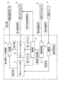
- the runout correction unit drive unit 70 includes a first feedback unit 90, a second feedback unit 91, a subtractor 92, a synthesis unit 93, a turning motion detection unit 94, and an adjustment unit 95.
- the first feedback unit 90 obtains the first value based on the first angular velocity signal output from the first gyro sensor 39.
- the first value is a value related to the driving force of the runout correction motor 40 based on the detection result of the first gyro sensor 39, that is, for runout correction for correcting image shake caused by the rotation of the runout correction unit 30. It refers to a value related to a driving force for driving the motor 40 (for example, a gain applied to the runout correction motor 40).
- the first feedback unit 90 outputs the first value to the synthesis unit 93.
- the second feedback unit 91 obtains a second value based on the displacement signal output from the subtractor 92.
- the second value is a value related to a driving force for driving the runout correction motor 40 in the direction of aligning the runout correction unit 30 with the reference position S (for example, a gain applied to the runout correction motor 40).
- the reference position S refers to the position of the runout correction unit 30 fixed by the fixing mechanism 50, for example, as shown in FIG.
- a reference position signal indicating the reference position S of the runout correction unit 30 is given to the subtractor 92.
- the subtractor 92 outputs a displacement signal indicating the displacement of the runout correction unit 30 from the reference position S by subtracting the reference position signal from the current position signal output from the position sensor 47.
- the synthesis unit 93 obtains a third value based on the first value and the second value, and outputs the third value to the runout correction motor 40.
- the third value is a value indicating a driving force for driving the runout correction motor 40 (for example, a current or a voltage input to the runout correction motor 40), and is a first value and a second value.
- the value is obtained by being synthesized by the synthesis unit 93.
- the composition by the composition unit 93 refers to an operation using, for example, addition and a constant.
- the runout correction unit drive unit 70 adjusts the third value by changing the degree of difference between the first value and the second value.
- the degree of difference refers to, for example, the ratio of the first value to the second value.
- the runout correction unit driving unit 70 changes the driving force for driving the runout correction motor 40 by adjusting the third value, thereby controlling the runout correction unit 30.
- the first value is the driving force applied to the runout correction motor 40 to correct the image shake. Since it is a value related to, the accuracy of the vibration isolation operation is improved as compared with the case where the ratio of the second value is higher than the ratio of the first value.
- the second value is the runout correction motor 40 for aligning the runout correction unit 30 with the reference position S.
- the runout correction unit 30 Since it is a value related to the driving force given to, the runout correction unit 30 is in the reference position S regardless of the magnitude of the given vibration, as compared with the case where the ratio of the first value is higher than the ratio of the second value. It becomes easier to stay in. This is effective in preventing damage to the shake correction unit 30 when, for example, excessive vibration is applied to the binoculars 10.
- the turning motion detection unit 94 monitors the second angular velocity signal output from the second gyro sensor 80 during the period during which the vibration isolation operation using the vibration correction unit 30 is performed (hereinafter, referred to as “vibration isolation operation period”). By doing so, the usage status of the binoculars 10 is detected.
- the usage status refers to the status of the binoculars 10 in use, for example, the start and end of the turning operation.
- the turning motion refers to, for example, an motion of continuously changing the observation direction by the binoculars 10 with the position of the user using the binoculars 10 as an axis.
- the turning operation includes at least one of a panning operation for changing the observation direction in the X-axis direction and a tilting operation for changing the observation direction in the Z-axis direction.
- the anti-vibration control performed by the vibration correction unit driving unit 70 during the period during which the panning operation is performed (hereinafter referred to as “panning operation period”) will be described by taking the panning operation as an example.
- the panning operation is merely an example, and the period during which the chilling operation is performed in the same manner as the vibration isolation control performed by the shake correction unit drive unit 70 during the panning operation period (hereinafter, “chilling operation”).
- Anti-vibration control may be performed by the vibration correction unit drive unit 70 during the period). Further, the vibration isolation control during the panning operation period and the vibration isolation control during the tilting operation period may be performed in parallel by the vibration correction unit drive unit 70.
- the second gyro sensor 80 detects the vibration of the housing 11 rotating at a constant speed in one of the X-axis directions. That is, for example, as shown in the lower graph of FIG. 11, the second angular velocity signal output from the second gyro sensor 80 continues to maintain a constant value during the panning operation.
- the turning motion detection unit 94 monitors the second angular velocity signal, and for example, when the second angular velocity signal continues to maintain a constant value other than zero for a predetermined time, the panning motion is performed. to decide. In this case, the turning motion detection unit 94 performs a panning operation at the timing when the second angular velocity signal reaches a certain value (in the example shown in the lower part of FIG. 11, the timing at which the rise of the output of the second gyro sensor 80 is completed). Detected as the start timing of.
- the turning motion detection unit 94 reduces to zero after the second angular velocity signal continues to maintain a constant value for a predetermined time (for example, a time of about several hundred ms (milliseconds)).
- a predetermined time for example, a time of about several hundred ms (milliseconds)
- the predetermined time is a time derived as the lower limit time during which the panning operation is performed, for example, by a test using an actual machine and / or a computer simulation.
- the turning motion detection unit 94 detects the timing at which the second angular velocity signal reaches a predetermined threshold value as the end timing of the panning motion.
- the predetermined threshold value is, for example, zero. Note that zero is only an example, and is a value derived as the value of the second angular velocity signal when the panning operation is completed by, for example, a test with an actual machine and / or a computer simulation (for example, zero close to zero). Any value other than) will do.
- the turning motion detecting unit 94 transmits a start detection signal (see FIG. 10) indicating that the start of the panning operation is detected to the adjusting unit 95.
- a start detection signal (see FIG. 10) indicating that the start of the panning operation is detected
- an end detection signal (see FIG. 10) indicating that the end of the panning operation has been detected is transmitted to the adjusting unit 95.
- the adjusting unit 95 determines that the period from the reception of the start detection signal to the reception of the end detection signal is the panning operation period.
- the adjusting unit 95 changes the setting of the filter function in the first gyro sensor 39 between the anti-vibration operation period and the panning operation period. Further, the adjusting unit 95 changes the parameters given to the first feedback unit 90 and the second feedback unit 91 between the vibration isolation operation period and the panning operation period.
- the first gyro sensor 39 has a high-pass filter (HPF) for removing signals of the first frequency F1 or lower and a low-pass filter (HPF) for removing signals of the second frequency F2 or higher as filter functions. LPF) and.
- HPF high-pass filter
- HPF low-pass filter
- LPF low-pass filter
- reference numeral 97 indicates an example of an output signal by HPF
- reference numeral 98 indicates an example of an output signal by LPF.
- the first frequency F1 and the second frequency F2 can be changed.
- the first gyro sensor 39 uses this filter function to set the first frequency F1 as the lower limit and the second frequency F2 as the upper limit. It is possible to output a signal in the frequency band.
- the first frequency F1 and the second frequency F2 are set by the adjusting unit 95.
- the adjusting unit 95 has a wide frequency band WB defined by the first frequency F1-1 and the second frequency F2-1 (see the middle stage of FIG. 12), and the first frequency F1-.
- the detectable frequency band of the first gyro sensor 39 (hereinafter, simply referred to as “detectable frequency band”). ) Is changed.
- FIG. 12 the detectable frequency band of the first gyro sensor 39
- the first frequency F1-2 of the narrow frequency band NB is a value on the higher frequency side than the first frequency F1-1 of the wide frequency band WB, and is the first of the narrow frequency band NB.
- the two-frequency F2-2 is a value on the lower frequency side than the second frequency F2-1 of the wide frequency band WB.
- the wide frequency band WB and the narrow frequency band NB may have a relatively wide and narrow relationship.
- the adjusting unit 95 sets the detectable frequency band to the wide frequency band WB. Further, when the adjustment unit 95 receives the start detection signal, the control unit 95 changes the detectable frequency band from the wide frequency band WB to the narrow frequency band NB. As a result, the detectable frequency band becomes narrower during the panning operation period than during the anti-vibration operation period. That is, during the panning operation period, the first gyro sensor 39 detects the vibration of the narrow frequency band NB narrower than the wide frequency band WB. Therefore, regarding the first value and the second value, the first value output from the first feedback unit 90 based on the first angular velocity signal is relatively small, and the second value is relatively large. .. Therefore, the runout correction unit 30 can easily follow the rotation of the housing 11 due to the panning operation, as compared with the case where the detectable frequency band is always fixed.
- the adjustment unit 95 receives the end detection signal, the detectable frequency band is changed from the narrow frequency band NB to the wide frequency band WB.
- the detectable frequency band becomes wider during the anti-vibration operation period than during the panning operation period. Therefore, since the first value is larger than the second value, the accuracy of the vibration isolation operation is improved as compared with the case where the detectable frequency band is always fixed.
- the adjusting unit 95 gives the first feedback unit 90 the first parameter A and the second feedback unit 91 the second parameter B.
- the first feedback unit 90 outputs, for example, the product of the first angular velocity signal and the first parameter A as the first value.
- the second feedback unit 91 outputs, for example, the product of the displacement signal and the second parameter B as the second value.
- the synthesizing unit 93 outputs the sum of the first value and the second value as the third value.
- the first parameter A and the second parameter B are values for normalizing by multiplying the first angular velocity signal and the displacement signal, respectively, and are values depending on the first angular velocity signal and the displacement signal.
- the adjusting unit 95 changes the ratio A: B (hereinafter referred to as a parameter ratio) between the first parameter A and the second parameter B, so that the first value and the second value in the third value are changed. Change the ratio with.
- the adjusting unit 95 sets the parameter ratio so that the second value is larger than the first value.
- the runout correction unit 30 can easily follow the rotation of the housing 11 due to the panning operation, as compared with the case where the parameter ratio is set so that the first value is larger than the second value.
- the adjusting unit 95 sets the parameter ratio so that the first value is larger than the second value.
- the accuracy of the vibration isolation operation by the vibration correction unit 30 is improved as compared with the case where the parameter ratio is set so that the second value is larger than the first value.
- the runout correction unit 30 is driven in the direction of adjusting to the reference position S during the panning operation period by changing the detectable frequency band and the parameter ratio.
- the first angular velocity signal output from the first gyro sensor 39 becomes large. This is because, for example, the vibration correction unit 30 that has been largely displaced from the reference position S due to the vibration isolation operation during the vibration isolation operation period is driven in the direction of adjusting to the reference position S when the start of the panning operation is detected. Because. After that, the runout correction unit 30 follows the rotation of the housing 11 while maintaining the state adjusted to the reference position S, so that the first angular velocity signal outputs the same value as the second angular velocity signal.
- the control process shown in FIG. 13 is realized by the CPU 62 executing the control program 72. Further, the control process shown in FIG. 13 is started when the power switch 15 is turned on.
- step ST101 the fixing mechanism driving unit 68 determines whether or not the anti-vibration switch 16 is turned on.
- the determination is affirmed and the control process shifts to step ST102. If the vibration isolation switch 16 is not turned on in step ST101, the determination is denied and the control process shifts to step ST114.
- step ST102 the fixing mechanism driving unit 68 determines whether or not the displacement member 55 is closed.
- the determination is affirmed, and the control process shifts to step ST103. If the displacement member 55 is open in step ST102, the determination is denied and the control process shifts to step ST106.
- step ST103 the fixing mechanism drive unit 68 displaces the displacement member 55 to the release position by driving the displacement member opening / closing motor 56. After that, the control process shifts to step ST104.
- step ST104 the runout correction unit drive unit 70 changes the detectable frequency band to the wide frequency band WB. After that, the control process shifts to step ST105.
- step ST105 the runout correction unit drive unit 70 changes the parameter ratio so that the first value is larger than the second value. After that, the control process proceeds to step ST106.
- step ST106 the runout correction unit drive unit 70 outputs the runout correction motor 40 to the runout correction motor 40 by outputting the third value calculated based on the first value and the second value to the runout correction motor 40.
- the runout correction unit 30 is controlled by driving the runout correction motor 40.
- the first value is set to be larger than the second value in the third value, so that the second value is the first.
- the accuracy of the vibration isolation operation by the vibration correction unit 30 is improved as compared with the case where the value is set to be larger than the value.
- step ST107 the turning motion detection unit 94 monitors the second angular velocity signal to determine whether or not the panning motion of the housing 11 has started.
- the determination is affirmed and the control process shifts to step ST108. If the panning operation has not been started in step ST107, the determination is denied and the control process shifts to step ST112.
- step ST108 the runout correction unit drive unit 70 changes the detectable frequency band to the narrow frequency band NB. After that, the control process proceeds to step ST109.
- step ST109 the runout correction unit drive unit 70 changes the parameter ratio so that the second value is larger than the first value. After that, the control process shifts to step ST110.
- step ST110 the runout correction unit drive unit 70 outputs the runout correction motor 40 to the runout correction motor 40 by outputting the third value calculated based on the first value and the second value to the runout correction motor 40.
- the runout correction unit 30 is controlled by driving the runout correction motor 40.
- the second value is set to be larger than the first value in the third value, so that the first value is the second value.
- the runout correction unit 30 can easily follow the panning operation of the housing 11 as compared with the case where it is set to be larger than the above.
- step ST111 the turning motion detection unit 94 monitors the second angular velocity signal to determine whether or not the panning motion of the housing 11 has been completed.
- the determination is affirmed, and the control process shifts to step ST104. If the panning operation is not completed in step ST111, the determination is denied and the control process shifts to step ST110.
- step ST112 the fixing mechanism drive unit 68 determines whether or not the anti-vibration switch 16 has been turned off. When the anti-vibration switch 16 is turned off in step ST112, the determination is affirmed and the control process shifts to step ST113. If the vibration isolation switch 16 is not turned off in step ST112, the determination is denied and the control process shifts to step ST114.
- step ST113 the fixing mechanism driving unit 68 displaces the displacement member 55 to a fixed position by driving the displacement member opening / closing motor 56. After that, the control process shifts to step ST114.
- step ST114 the fixed mechanism drive unit 68 determines whether or not the power switch 15 has been turned off. When the power switch 15 is turned off in step ST114, the determination is affirmed, and the control process proceeds to step ST115. If the power switch 15 is not turned off in step ST114, the determination is denied and the control process proceeds to step ST101.
- step ST115 the fixing mechanism driving unit 68 determines whether or not the displacement member 55 is open. When the displacement member 55 is open in step ST115, the determination is affirmed, and the control process shifts to step ST116. If the displacement member 55 is closed in step ST115, the determination is denied and the control process ends.
- step ST116 the fixing mechanism driving unit 68 displaces the displacement member 55 to a fixed position by driving the displacement member opening / closing motor 56. After this, the control process ends.
- the vibration isolator according to the first embodiment includes the shake correction unit 30, the first gyro sensor 39 arranged in the shake correction unit 30, and the second gyro arranged in other than the shake correction unit 30. It includes a sensor 80 and a CPU 62.
- the shake correction unit drive unit 70 of the CPU 62 performs vibration isolation control based on the first angular velocity signal output from the first gyro sensor 39 and the second angular velocity signal output from the second gyro sensor 80. Therefore, according to the binoculars 10 according to the first embodiment, it is possible to realize vibration isolation according to the usage situation of the binoculars 10.
- the anti-vibration device is an integrated device.
- the vibration isolator includes a housing 11 in which the vibration correction unit 30 is housed, and the second gyro sensor 80 is arranged in the housing 11.
- the integrated device refers to, for example, a device integrated by a housing 11.
- the vibration detection shaft 38A of the X-axis gyro sensor 38 constituting the first gyro sensor 39 and the vibration detection shaft 80A of the second gyro sensor 80 are the rotation shafts of the vibration correction unit 30. It is parallel to 28. Further, the vibration detection shaft 37A of the Z-axis gyro sensor 37 constituting the first gyro sensor 39 and the vibration detection shaft 80B of the second gyro sensor 80 are parallel to the rotation shaft 29 of the shake correction unit 30.
- the first gyro It is easy to compare the first angular velocity signal, which is the output value of the sensor 39, with the second angular velocity signal, which is the output value of the second gyro sensor 80.
- the first gyro sensor 39 and the second gyro sensor 80 have the same sensitivity. Therefore, it is easier to compare the first angular velocity signal and the second angular velocity signal than when the sensitivities of the first gyro sensor 39 and the second gyro sensor 80 are different.
- the frequency band that can be detected by the second gyro sensor 80 is the same as the frequency band that can be detected by the first gyro sensor 39. Therefore, it is easier to compare the first angular velocity signal and the second angular velocity signal as compared with the case where the frequency band that can be detected by the second gyro sensor 80 is different from the frequency band that can be detected by the first gyro sensor 39.
- the vibration correction unit drive unit 70 controls the vibration isolation control to bring the first angular velocity signal closer to a predetermined value, for example, zero. Therefore, in the anti-vibration control, the anti-vibration performance of the binoculars 10 can be improved as compared with the case where the control for bringing the first angular velocity signal close to zero is not performed.
- the swing motion detection unit 94 of the vibration correction unit drive unit 70 detects the usage status of the vibration isolation device based on the second angular velocity signal, and vibration isolation is based on the detection result. Take control. Therefore, it is possible to perform vibration isolation according to the usage status of the vibration isolator with higher accuracy than when the usage status of the vibration isolator is not detected.
- the usage status is the start and end of the turning operation of the anti-vibration device. Therefore, according to this configuration, it is possible to realize vibration isolation in consideration of the start and end of the turning operation of the vibration isolation device.
- the turning operation is at least one of the panning operation and the tilting operation. Therefore, vibration isolation according to the panning operation and / or the tilting operation can be realized.
- the detectable frequency band can be changed.
- the runout correction unit drive unit 70 sets the detectable frequency band to the wide frequency band WB when the runout correction unit 30 performs the vibration isolation operation. Further, when the runout correction unit drive unit 70 detects the start of the panning operation of the housing 11, the detectable frequency is changed to the narrow frequency band NB. Therefore, the runout correction unit 30 can easily follow the turning operation of the housing 11 during the panning operation period, as compared with the case where the detectable frequency band is not changed.
- the vibration isolation operation can be performed more accurately during the vibration isolation operation period than in the case where the detectable frequency band is not changed.
- the binoculars 10 according to the first embodiment include a vibration isolator, an optical system for the right eye, and an optical system for the left eye. Therefore, it is possible to realize vibration isolation according to the usage situation of the binoculars 10, as compared with the case where the binoculars 10 are not provided with the vibration isolation device.
- the first gyro sensor 39 is arranged at the center of the right eye optical system and the left eye optical system. Therefore, the binoculars 10 can be vibration-proofed more accurately than when the first gyro sensor 39 is arranged at a position other than the center of the right-eye optical system and the left-eye optical system.
- the swivel motion detection unit 94 detects the start and end of the swivel motion of the housing 11 based on the second angular velocity signal, but the technique of the present disclosure is not limited to this, and the casing is not limited to this. Only one of the start and end of the turning motion of the body 11 may be detected.
- the turning motion detection unit 94 detects the start and end of the turning motion of the housing 11 as a usage status based on the second angular velocity signal, but the technique of the present disclosure is based on this. Not limited to this, the camera shake of the user may be included. Further, for example, as a usage situation, a situation caused by the usage environment of the binoculars 10 may be detected.
- examples of the environment in which the binoculars 10 are used include the sea, which is subject to vibrations due to waves, or the inside of a vehicle, which is subject to vibrations from a road surface such as a road or a railroad track and vibrations from an engine or a motor. As a result, vibration isolation can be realized according to the usage environment of the binoculars 10.
- the first gyro sensor 39 Due to the filter function provided in the first gyro sensor 39, the first gyro sensor 39 has a characteristic that the output signal swings to the minus side when the input signal falls to zero. As an example, as shown in FIG. 14, the second angular velocity signal 104 output from the second gyro sensor 80 falls toward zero at the timing when the panning operation of the housing 11 ends. The first angular velocity signal 102 output from the first gyro sensor 39 also falls toward zero following the end of the panning operation, but the first angular velocity signal 102 is on the minus side as shown by the dotted line in FIG. It swings greatly.
- the adjusting unit 95 sets the HPF of the first gyro sensor 39. 1
- the value of frequency F1 that is, the lower limit of the detectable frequency band is changed to the high frequency side.
- the adjusting unit 95 changes the detectable frequency band to the wide frequency band WB as in the first embodiment. Therefore, the anti-vibration operation of the binoculars 10 is performed with high accuracy.
- the adjusting unit 95 changes the lower limit of the detectable frequency band to the high frequency side. Therefore, the noise of the first angular velocity signal caused by the filter function can be converged faster than the case where the lower limit of the detectable frequency band is not changed to the high frequency side.
- the vibration correction unit driving unit 71 includes a vibration measuring unit 96 instead of the turning motion detecting unit 94.
- Other configurations of the runout correction unit drive unit 71 are the same as those of the runout correction unit drive unit 70 according to the first embodiment.
- the vibration measuring unit 96 measures the amplitude and frequency of vibration given to the housing 11 based on the second angular velocity signal output from the second gyro sensor 80.
- the vibration measuring unit 96 outputs the measured amplitude and frequency to the adjusting unit 95.
- the adjusting unit 95 adjusts the detectable frequency band and the parameter ratio based on the input amplitude and frequency.
- the adjustment is made when the amplitude measured by the vibration measuring unit 96 is smaller than the default value and the frequency is lower than the default value, that is, in the case of small amplitude low frequency vibration.
- Part 95 sets the parameter ratio so that the first value is larger than the second value. This improves the vibration isolation performance against small amplitude vibration.
- the adjusting unit 95 widens the detectable frequency band toward the low frequency side. Specifically, as shown in FIG. 17, the adjusting unit 95 sets the first frequency to F1-3 in the detectable frequency band defined by, for example, the first frequency F1-3 and the second frequency F2-3. Change to a lower value F1-4. This improves the vibration isolation performance against low frequency vibration.
- the adjusting unit 95 when the amplitude measured by the vibration measuring unit 96 is larger than the default value and the frequency is higher than the default value, that is, in the case of large amplitude high frequency vibration, the adjusting unit 95 The parameter ratio is set so that the second value is larger than the first value. This improves the vibration isolation performance against large amplitude vibration. Further, the adjusting unit 95 widens the detectable frequency band toward the high frequency side. Specifically, as shown in FIG. 18, the adjusting unit 95 sets the second frequency to F2-3 in the detectable frequency band defined by, for example, the first frequency F1-3 and the second frequency F2-3. Change to a higher value F2-4. This improves the vibration isolation performance against high frequency vibration.
- the vibration measuring unit 96 measures the frequency of the vibration given to the binoculars 10 based on the second angular velocity signal, and the adjusting unit 95 measures the measured frequency. Accordingly, the detectable frequency band is widened to at least one of the high frequency side and the low frequency side. Therefore, the vibration isolation performance for at least one of high frequency vibration and low frequency vibration can be improved as compared with the case where the detectable frequency band is always constant regardless of the frequency of vibration given to the binoculars 10.
- the vibration measuring unit 96 stores the amplitude data and the frequency data of the vibration measured based on the second angular velocity signal in the working memory 66 of the computer 60.
- the amplitude and frequency of vibration are continuously sampled during vibration isolation control.
- the vibration measuring unit 96 measures the amplitude and frequency for each cycle, and averages the measured amplitude and frequency.
- the vibration measuring unit 96 recognizes that the usage status of the binoculars 10 has changed, and works on the average amplitude and average frequency up to the previous time as one environmental data. It is stored in the memory 66.
- the vibration measuring unit 96 repeats the above process during vibration isolation control.
- the adjusting unit 95 selects the most frequent environment (for example, frequency 7 Hz and small amplitude) based on the amplitude data and frequency data stored in the working memory 66 until then. The selected environment is adopted as the usage status of the binoculars 10 when the next vibration isolation control is started.
- the adjusting unit 95 determines the default value of the detectable frequency band and the default value of the parameter ratio based on the selected environment.
- the default value of the detectable frequency band is set when the vibration isolator including the CPU 62 including the runout correction unit 30, the first gyro sensor 39, the second gyro sensor 80, and the runout correction unit drive unit 71 is started.
- the anti-vibration device is activated when the anti-vibration switch 16 is turned on and the fixing mechanism 50 is released.
- the default value of the parameter ratio refers to the parameter ratio set when the vibration isolator is started.
- the adjusting unit 95 determines the control content of the anti-vibration control at the time of starting the anti-vibration device based on the selected average amplitude and average frequency. As a result, vibration isolation performance according to the vibration tendency is provided from the start of the vibration isolation operation.
- the vibration measuring unit 96 stores the average value of the amplitude and frequency of the vibration measured based on the second angular velocity signal in the working memory 66, and the adjusting unit 95 stores the average value.
- the control content of the vibration isolation control at the time of starting the vibration isolation device is determined based on the vibration and the frequency stored in the working memory 66. Therefore, as compared with the case where the control content of the anti-vibration control at the time of starting the anti-vibration device is not determined based on the amplitude and frequency stored in the working memory 66, the tendency of vibration is adjusted immediately after the start of the anti-vibration device. Anti-vibration performance can be provided.
- the vibration measuring unit 96 determines the control content of the vibration isolating control at the time of starting the vibration isolating device based on the vibration and the frequency stored in the working memory 66.
- the disclosed technology is not limited to this.
- the vibration measuring unit 96 may determine the control content of the vibration isolating control at the time of starting the vibration isolating device based on either vibration or frequency. Further, the vibration measuring unit 96 stores both the amplitude data and the frequency data in the working memory 66, but the vibration measuring unit 96 stores either the amplitude data or the frequency data in the working memory 66. You may.
- the adjusting unit 95 calculates the average amplitude and the average frequency from the amplitude data and the frequency data, but the technique of the present disclosure is not limited to this.
- the adjusting unit 95 calculates the mode or median instead of the average value of the amplitude and frequency, and based on the calculated mode or median, the control content of the vibration isolation control at the time of starting the vibration isolator. May be determined.
- a matrix table 106 for searching the detectable frequency band and the parameter ratio based on the frequency and amplitude of the given vibration is prepared in advance and working. It is stored in the memory 66.
- frequency values X1, X2, ... are described in the row direction of the matrix table 106
- amplitude values Y1, Y2, ... are described in the column direction.
- Matrix In each cell of Table 106, the detectable frequency band and the parameter ratio determined for each combination of frequency and amplitude are described.
- Matrix Table 106 shows the detectable frequency for obtaining the optimum third value in vibration isolation control while changing the frequency and amplitude of the vibration applied to the binoculars 10, for example, by a test with an actual machine and / or a computer simulation. Obtained by calculating the band and parameter ratio.
- the optimum third value in the vibration isolation control is to cancel the image deflection due to vibration as much as possible while preventing the fixing rod 46 and / or the fixing mechanism 50 from being damaged due to the rotation of the vibration correction unit 30.
- the value about the driving force of the runout correction motor 40 that can be made is shown.
- the vibration measuring unit 96 measures the amplitude and frequency of the vibration given to the binoculars 10 based on the second angular velocity signal, and outputs the measured amplitude and frequency to the adjusting unit 95.
- the adjusting unit 95 obtains the detectable frequency band and the parameter ratio corresponding to the input amplitude and frequency with reference to the matrix table 106.
- the adjusting unit 95 sets the first gyro sensor 39, the first feedback unit 90, and the second feedback unit 91 using the acquired detectable frequency band and parameter ratio.
- the detectable frequency band and the parameter ratio are determined for each combination of the amplitude and frequency of the vibration given to the binoculars 10. Therefore, an appropriate detectable frequency band and parameter ratio can be used according to the combination of the amplitude and frequency of the vibration given to the binoculars 10.
- the matrix table 106 describes the detectable frequency band and the parameter ratio defined for each combination of frequency and amplitude, but the technique of the present disclosure is not limited to this.
- Matrix Table 106 may list at least one of the detectable frequency band and the parameter ratio.
- the adjusting unit 95 sets the runout correction unit driving unit 71 using the detectable frequency band and the parameter ratio acquired from the matrix table 106, and the technique of the present disclosure is based on this. Not limited. The adjusting unit 95 may set the runout correction unit driving unit 71 using at least one of the detectable frequency band and the parameter ratio acquired from the matrix table 106.
- an arithmetic expression may be used in which the frequency and the amplitude are the independent variables and the detectable frequency band and the parameter ratio are the dependent variables. Even when this calculation formula is used, the detectable frequency band and the parameter ratio can be determined for each combination of the amplitude and frequency of the vibration given to the binoculars 10, so that the same effect as described above can be obtained.
- the vibration measuring unit 96 calculates the moving distance of the housing 11 due to the given vibration by integrating the second angular velocity signal, and further calculates it.
- the displacement of the vibration correction unit 30 from the reference position S is predicted based on the moving distance of the housing 11.
- the adjusting unit 95 controls to fix the runout correction unit at the reference position when the predicted displacement value of the runout correction unit 30 (hereinafter, simply referred to as “displacement predicted value”) exceeds a predetermined range. More specifically, the adjusting unit 95 has a displacement predicted value (for example, an absolute value of the displacement predicted value) from a predetermined threshold value (for example, a displacement limit value determined according to the sizes of the openings 54a and 51a). If it is also large, control is performed to fix the runout correction unit 30 at the reference position S. As a result, for example, when excessive vibration is applied to the binoculars 10, the runout correction unit 30 is prevented from being displaced and damaged in excess of the specifications of the runout correction unit 30.
- a displacement predicted value for example, an absolute value of the displacement predicted value
- a predetermined threshold value for example, a displacement limit value determined according to the sizes of the openings 54a and 51a
- the vibration measuring unit 96 predicts the displacement of the vibration correction unit 30 by integrating the second angular velocity signal.
- the adjusting unit 95 controls to fix the runout correction unit 30 at the reference position S. Therefore, it is possible to prevent the runout correction unit 30 from being damaged.
- the ratio is exemplified as the degree of difference between the first value and the second value, but the technique of the present disclosure is not limited to this.
- Other examples of the degree of difference include, for example, the absolute value of the difference between the first value and the second value, or the absolute value of the ratio ⁇ the difference.
- the first feedback unit 90 outputs the product of the first angular velocity signal and the first parameter A as the first value
- the second feedback unit 91 outputs the displacement signal and the second parameter B.
- the product of and is output as the second value but the technique of the present disclosure is not limited to this.
- the first value may be the absolute value of the difference between the first angular velocity signal and the first parameter A
- the second value is the absolute value of the difference between the displacement signal and the second parameter B. You may.
- the adjusting unit 95 can change the degree of difference between the first value and the second value in the third value by changing the first parameter A and the second parameter B.
- the adjusting unit 95 changes both the detectable frequency band and the parameter ratio based on the second angular velocity signal, but the technique of the present disclosure is not limited to this. As shown in FIG. 22 as an example, the adjusting unit 95 may change only the detectable frequency band based on the second angular velocity signal. Further, as shown in FIG. 23 as an example, the adjusting unit 95 may change only the parameter ratio based on the second angular velocity signal. In either case, the degree of difference between the first value and the second value can be changed by changing the detectable frequency band or the parameter ratio, so that the same effect as in each of the above embodiments can be obtained. Can be done.
- first gyro sensor 39 and the second gyro sensor 80 different types are used as the first gyro sensor 39 and the second gyro sensor 80, but the technique of the present disclosure is not limited to this, and the same type of gyro sensor is used. May be used. Further, the first gyro sensor 39 has a filter function, but the second gyro sensor 80 may or may not have a filter function.
- the second gyro sensor 80 has the same sensitivity as the first gyro sensor 39, but the technique of the present disclosure is not limited to this, and the second gyro sensor 80 is more than the first gyro sensor 39. It may have low sensitivity. The reason for this will be explained below.
- the vibration correction unit drive unit 70 controls the vibration correction unit 30 so that the first angular velocity signal output from the first gyro sensor 39 approaches a minute value such as zero, so that the first It is preferable that the sensitivity of the gyro sensor 39 is high.
- the second gyro sensor 80 detects the vibration applied to the binoculars 10.
- the sensitivity of the second gyro sensor 80 may be lower than that of the first gyro sensor 39. Since the second gyro sensor 80 has a lower sensitivity than the first gyro sensor 39, the accuracy of the vibration isolation control is improved as compared with the case where the second gyro sensor 80 has a higher sensitivity than the first gyro sensor 39. be able to.
- the frequency band that can be detected by the second gyro sensor 80 is the same as the frequency band that can be detected by the first gyro sensor 39, but the technique of the present disclosure is not limited to this.
- the frequency band that can be detected by the second gyro sensor 80 may be wider than the frequency band that can be detected by the first gyro sensor 39. The reason for this will be explained below.
- the shake correction unit drive unit 70 performs vibration isolation control so that the first angular velocity signal output from the first gyro sensor 39 approaches, for example, zero.
- the first The angular velocity signal is preferably a signal that does not contain high-frequency and low-frequency components in the frequency band that are unnecessary for runout correction.
- the first gyro sensor 39 uses a filter function to remove high-frequency and low-frequency components in the frequency band that are unnecessary for runout correction, so that a signal that becomes noise is used as the first angular velocity signal used for runout correction.
- the removed angular velocity signal can be output.
- the second angular velocity signal output from the second gyro sensor 80 is used to detect the usage status of the binoculars 10, and there is no problem even if it contains high frequency and low frequency components. Therefore, it is preferable that the frequency band that can be detected by the second gyro sensor 80 is wider than the frequency band that can be detected by the first gyro sensor 39.
- the second gyro sensor 80 is attached to the front of the housing 11 and the lower side of the objective cylinder 27, but the technique of the present disclosure is not limited to this.
- the second gyro sensor 80 may be attached to an object that holds the runout correction unit 30, and may be attached to a frame that holds the runout correction unit 30, for example. Thereby, the second gyro sensor 80 can detect the vibration applied to the object holding the shake correction unit 30, for example, the frame holding the shake correction unit 30.
- control program 72 may be stored in the storage medium 100.
- An example of the storage medium 100 is any portable storage medium such as an SSD or a USB memory.
- the control program 72 stored in the storage medium 100 is installed in the computer 60 and executed by the CPU 62 on the working memory 66.
- control program 72 may be stored in a storage unit such as another computer or a server device connected to the computer 60 via a communication network (not shown). In this case, the control program 72 may be downloaded from a storage unit such as another computer or a server device to the program memory 64 and installed in the computer 60.
- control program 72 it is not necessary to store all of the control program 72 in the storage unit of another computer or server device connected to the computer 60, or the program memory 64, and a part of the control program 72 is stored. May be good.
- the following various processors may be used as the hardware structure of the computer 60 that executes various processes of the fixed mechanism drive unit 68 and the runout correction unit drive units 70 and 71.
- the various processors include a CPU 62, which is a general-purpose processor that executes software (for example, a control program 72) and functions as various processing units, and a processor whose circuit configuration can be changed after manufacturing an FPGA or the like. Included are dedicated electrical circuits and the like, which are processors having a circuit configuration specifically designed to perform specific processes such as PLDs and / or ASICs.
- One processing unit may be composed of one of these various processors, or may be a combination of two or more processors of the same type or different types (for example, a combination of a plurality of FPGAs and / or a CPU). It may be configured in combination with FPGA). Further, a plurality of processing units may be configured by one processor.
- one processor is configured by a combination of one or more CPUs and software, as represented by a computer such as a client and a server.
- the processor functions as a plurality of processing units.
- SoC there is a mode in which a processor that realizes the functions of the entire system including a plurality of processing units with one IC chip is used.
- the various processing units are configured by using one or more of the above-mentioned various processors as a hardware-like structure.
- the technique of the present disclosure can be appropriately combined with the various embodiments described above and / or various modifications. Further, it is of course not limited to the above embodiment, and various configurations can be adopted as long as they do not deviate from the gist. Further, the technique of the present disclosure extends to a storage medium for storing the program non-temporarily in addition to the program.
- a and / or B is synonymous with "at least one of A and B". That is, “A and / or B” means that it may be only A, it may be only B, or it may be a combination of A and B. Further, in the present specification, when three or more matters are connected and expressed by "and / or", the same concept as “A and / or B" is applied.
- a vibration isolator with a runout correction unit The first vibration detector arranged in the shake correction unit and The second vibration detector arranged in addition to the above-mentioned runout correction unit, and With a processor, The processor performs vibration isolation control based on the first output value output from the first vibration detector and the second output value output from the second vibration detector.
- the detectable frequency band of the first vibration detector is a vibration isolator defined for each combination of the amplitude and frequency of the vibration given to the vibration isolator.
Landscapes
- Physics & Mathematics (AREA)
- General Physics & Mathematics (AREA)
- Optics & Photonics (AREA)
- Engineering & Computer Science (AREA)
- Multimedia (AREA)
- Signal Processing (AREA)
- Astronomy & Astrophysics (AREA)
- Adjustment Of Camera Lenses (AREA)
- Telescopes (AREA)
- Studio Devices (AREA)
Abstract
L'invention concerne un dispositif anti-vibration ayant une unité de correction de tremblement. Ce dispositif anti-vibration est pourvu d'un premier détecteur de vibrations disposé dans l'unité de correction de tremblement, un second détecteur de vibrations disposé à l'extérieur de l'unité de correction de tremblement, et un processeur, et le processeur effectue une commande anti-vibration sur la base d'une première valeur de sortie fournie par le premier détecteur de vibrations et d'une seconde valeur de sortie fournie par le second détecteur de vibrations.
Priority Applications (3)
| Application Number | Priority Date | Filing Date | Title |
|---|---|---|---|
| JP2022526870A JP7252419B2 (ja) | 2020-05-29 | 2021-05-12 | 防振装置、光学装置、双眼鏡、防振装置の制御方法、及びプログラム |
| CN202180038715.4A CN115698842B (zh) | 2020-05-29 | 2021-05-12 | 防振装置、光学装置、双筒望远镜、防振装置的控制方法及存储介质 |
| US18/055,837 US20230075081A1 (en) | 2020-05-29 | 2022-11-16 | Anti-vibration device, optical device, binocle, control method for anti-vibration device, and program |
Applications Claiming Priority (2)
| Application Number | Priority Date | Filing Date | Title |
|---|---|---|---|
| JP2020-094686 | 2020-05-29 | ||
| JP2020094686 | 2020-05-29 |
Related Child Applications (1)
| Application Number | Title | Priority Date | Filing Date |
|---|---|---|---|
| US18/055,837 Continuation US20230075081A1 (en) | 2020-05-29 | 2022-11-16 | Anti-vibration device, optical device, binocle, control method for anti-vibration device, and program |
Publications (1)
| Publication Number | Publication Date |
|---|---|
| WO2021241237A1 true WO2021241237A1 (fr) | 2021-12-02 |
Family
ID=78723396
Family Applications (1)
| Application Number | Title | Priority Date | Filing Date |
|---|---|---|---|
| PCT/JP2021/018102 Ceased WO2021241237A1 (fr) | 2020-05-29 | 2021-05-12 | Dispositif anti-vibration, dispositif optique, jumelles, procédé de commande pour dispositif anti-vibration, et programme |
Country Status (4)
| Country | Link |
|---|---|
| US (1) | US20230075081A1 (fr) |
| JP (1) | JP7252419B2 (fr) |
| CN (1) | CN115698842B (fr) |
| WO (1) | WO2021241237A1 (fr) |
Cited By (1)
| Publication number | Priority date | Publication date | Assignee | Title |
|---|---|---|---|---|
| WO2025047474A1 (fr) * | 2023-08-28 | 2025-03-06 | 富士フイルム株式会社 | Dispositif de commande, procédé de commande et programme de commande |
Citations (5)
| Publication number | Priority date | Publication date | Assignee | Title |
|---|---|---|---|---|
| JP2009038515A (ja) * | 2007-07-31 | 2009-02-19 | Canon Marketing Japan Inc | 防振装置および防振方法およびプログラム |
| JP2009042328A (ja) * | 2007-08-07 | 2009-02-26 | Canon Inc | 光学機器 |
| JP2012018328A (ja) * | 2010-07-08 | 2012-01-26 | Canon Inc | 光学機器、撮像装置、及び光学機器の制御方法 |
| WO2014192464A1 (fr) * | 2013-05-30 | 2014-12-04 | 富士フイルム株式会社 | Dispositif de correction de tremblement et dispositif d'observation |
| JP2015114615A (ja) * | 2013-12-13 | 2015-06-22 | 日本電産サンキョー株式会社 | 撮影用光学装置および撮影用光学装置の制御方法 |
Family Cites Families (6)
| Publication number | Priority date | Publication date | Assignee | Title |
|---|---|---|---|---|
| JP4666787B2 (ja) * | 2001-02-09 | 2011-04-06 | キヤノン株式会社 | 振動検出装置及び像振れ補正装置 |
| JP4992478B2 (ja) * | 2007-03-07 | 2012-08-08 | 株式会社ニコン | ブレ補正ユニット、レンズ鏡筒、カメラ |
| JP2009008858A (ja) * | 2007-06-27 | 2009-01-15 | Olympus Imaging Corp | ブレ補正装置及び撮像装置 |
| JP5094606B2 (ja) * | 2008-07-15 | 2012-12-12 | キヤノン株式会社 | 像振れ補正装置およびそれを備えた光学機器、撮像装置、像振れ補正装置の制御方法 |
| JP5230398B2 (ja) * | 2008-12-19 | 2013-07-10 | キヤノン株式会社 | 撮像装置及びその制御方法 |
| JP6381433B2 (ja) * | 2014-12-15 | 2018-08-29 | オリンパス株式会社 | カメラシステム及びそのブレ補正方法 |
-
2021
- 2021-05-12 WO PCT/JP2021/018102 patent/WO2021241237A1/fr not_active Ceased
- 2021-05-12 JP JP2022526870A patent/JP7252419B2/ja active Active
- 2021-05-12 CN CN202180038715.4A patent/CN115698842B/zh active Active
-
2022
- 2022-11-16 US US18/055,837 patent/US20230075081A1/en active Pending
Patent Citations (5)
| Publication number | Priority date | Publication date | Assignee | Title |
|---|---|---|---|---|
| JP2009038515A (ja) * | 2007-07-31 | 2009-02-19 | Canon Marketing Japan Inc | 防振装置および防振方法およびプログラム |
| JP2009042328A (ja) * | 2007-08-07 | 2009-02-26 | Canon Inc | 光学機器 |
| JP2012018328A (ja) * | 2010-07-08 | 2012-01-26 | Canon Inc | 光学機器、撮像装置、及び光学機器の制御方法 |
| WO2014192464A1 (fr) * | 2013-05-30 | 2014-12-04 | 富士フイルム株式会社 | Dispositif de correction de tremblement et dispositif d'observation |
| JP2015114615A (ja) * | 2013-12-13 | 2015-06-22 | 日本電産サンキョー株式会社 | 撮影用光学装置および撮影用光学装置の制御方法 |
Cited By (1)
| Publication number | Priority date | Publication date | Assignee | Title |
|---|---|---|---|---|
| WO2025047474A1 (fr) * | 2023-08-28 | 2025-03-06 | 富士フイルム株式会社 | Dispositif de commande, procédé de commande et programme de commande |
Also Published As
| Publication number | Publication date |
|---|---|
| CN115698842B (zh) | 2026-01-06 |
| CN115698842A (zh) | 2023-02-03 |
| JP7252419B2 (ja) | 2023-04-04 |
| JPWO2021241237A1 (fr) | 2021-12-02 |
| US20230075081A1 (en) | 2023-03-09 |
Similar Documents
| Publication | Publication Date | Title |
|---|---|---|
| JP2007183356A (ja) | 防振装置 | |
| WO2021241237A1 (fr) | Dispositif anti-vibration, dispositif optique, jumelles, procédé de commande pour dispositif anti-vibration, et programme | |
| JP4807855B2 (ja) | 防振装置および防振方法およびプログラム | |
| JP2004194157A (ja) | 撮像装置 | |
| JP6280218B2 (ja) | 防振光学系、望遠光学系、双眼鏡、及び防振ユニット | |
| JPH06250100A (ja) | 像安定化装置 | |
| KR20200052705A (ko) | 외란을 상쇄하는 시선 안정화 시스템 | |
| JP7209111B2 (ja) | 光学装置、双眼鏡、光学装置の制御方法、及びプログラム | |
| JP2004212878A (ja) | 像安定化装置およびこの像安定化装置を備えた双眼鏡 | |
| CN111277735A (zh) | 水下云台、水下成像系统及水下机器人 | |
| JP6395957B2 (ja) | 防振装置及び双眼鏡 | |
| JP7348949B2 (ja) | 物体を結像するための光学系及び当該光学系の操作方法 | |
| JP7313808B2 (ja) | レンズ装置、撮像装置及びカメラシステム | |
| JPH06250099A (ja) | 像安定化装置 | |
| JP3729214B2 (ja) | 像ブレ補正カメラ | |
| JP2011053240A5 (fr) | ||
| JP7281957B2 (ja) | 防振制御装置及び方法、及び撮像システム | |
| JPWO2017110340A1 (ja) | 防振装置及び双眼鏡 | |
| JP2001100106A (ja) | 像安定化装置 | |
| JP5166761B2 (ja) | 望遠鏡の防振装置 | |
| JP2018004780A (ja) | 光学機器 | |
| JP7770139B2 (ja) | 防振制御装置及び方法、撮像装置、及びレンズ装置 | |
| JP2001075014A (ja) | 像安定化装置 | |
| JP4033431B2 (ja) | 像安定化装置 | |
| JPH10191153A (ja) | 撮像機器の振れ補正方法及び装置並びに記憶媒体 |
Legal Events
| Date | Code | Title | Description |
|---|---|---|---|
| 121 | Ep: the epo has been informed by wipo that ep was designated in this application |
Ref document number: 21810895 Country of ref document: EP Kind code of ref document: A1 |
|
| ENP | Entry into the national phase |
Ref document number: 2022526870 Country of ref document: JP Kind code of ref document: A |
|
| NENP | Non-entry into the national phase |
Ref country code: DE |
|
| 122 | Ep: pct application non-entry in european phase |
Ref document number: 21810895 Country of ref document: EP Kind code of ref document: A1 |