WO2021255794A1 - Système de communication sans fil, procédé, dispositif et programme de commande pour système de communication sans fil - Google Patents
Système de communication sans fil, procédé, dispositif et programme de commande pour système de communication sans fil Download PDFInfo
- Publication number
- WO2021255794A1 WO2021255794A1 PCT/JP2020/023452 JP2020023452W WO2021255794A1 WO 2021255794 A1 WO2021255794 A1 WO 2021255794A1 JP 2020023452 W JP2020023452 W JP 2020023452W WO 2021255794 A1 WO2021255794 A1 WO 2021255794A1
- Authority
- WO
- WIPO (PCT)
- Prior art keywords
- wireless communication
- seed
- communication system
- resource mapping
- mapping pattern
- Prior art date
- Legal status (The legal status is an assumption and is not a legal conclusion. Google has not performed a legal analysis and makes no representation as to the accuracy of the status listed.)
- Ceased
Links
Images








Classifications
-
- H—ELECTRICITY
- H04—ELECTRIC COMMUNICATION TECHNIQUE
- H04W—WIRELESS COMMUNICATION NETWORKS
- H04W24/00—Supervisory, monitoring or testing arrangements
- H04W24/02—Arrangements for optimising operational condition
-
- H—ELECTRICITY
- H04—ELECTRIC COMMUNICATION TECHNIQUE
- H04W—WIRELESS COMMUNICATION NETWORKS
- H04W36/00—Hand-off or reselection arrangements
- H04W36/0005—Control or signalling for completing the hand-off
- H04W36/0055—Transmission or use of information for re-establishing the radio link
- H04W36/0072—Transmission or use of information for re-establishing the radio link of resource information of target access point
-
- H—ELECTRICITY
- H04—ELECTRIC COMMUNICATION TECHNIQUE
- H04L—TRANSMISSION OF DIGITAL INFORMATION, e.g. TELEGRAPHIC COMMUNICATION
- H04L5/00—Arrangements affording multiple use of the transmission path
- H04L5/003—Arrangements for allocating sub-channels of the transmission path
- H04L5/0048—Allocation of pilot signals, i.e. of signals known to the receiver
- H04L5/005—Allocation of pilot signals, i.e. of signals known to the receiver of common pilots, i.e. pilots destined for multiple users or terminals
-
- H—ELECTRICITY
- H04—ELECTRIC COMMUNICATION TECHNIQUE
- H04L—TRANSMISSION OF DIGITAL INFORMATION, e.g. TELEGRAPHIC COMMUNICATION
- H04L5/00—Arrangements affording multiple use of the transmission path
- H04L5/003—Arrangements for allocating sub-channels of the transmission path
- H04L5/0053—Allocation of signalling, i.e. of overhead other than pilot signals
-
- H—ELECTRICITY
- H04—ELECTRIC COMMUNICATION TECHNIQUE
- H04L—TRANSMISSION OF DIGITAL INFORMATION, e.g. TELEGRAPHIC COMMUNICATION
- H04L5/00—Arrangements affording multiple use of the transmission path
- H04L5/0091—Signalling for the administration of the divided path, e.g. signalling of configuration information
- H04L5/0094—Indication of how sub-channels of the path are allocated
-
- H—ELECTRICITY
- H04—ELECTRIC COMMUNICATION TECHNIQUE
- H04W—WIRELESS COMMUNICATION NETWORKS
- H04W72/00—Local resource management
- H04W72/04—Wireless resource allocation
Definitions
- the present invention relates to a technique for controlling a wireless communication system.
- the present invention relates to a technique for controlling a specific signal such as a synchronization signal or a reference signal used in a wireless communication system.
- Non-Patent Document 1 discloses the physical layer specifications of NR (New Radio), which is a wireless communication method of the 5th generation mobile communication system (5G).
- NR New Radio
- various reference signals are defined separately from the payload of the data / control signal and are mapped to the radio resource (RE).
- RE radio resource
- a plurality of "resource mapping patterns”, which are patterns of mapping positions of reference signals, are defined. The same applies to the synchronization signal used for the initial access.
- Specific signals such as synchronization signals and reference signals are series signals generated based on seeds.
- the seed contains a cell ID.
- the specific signal is a quasi-orthogonal M-sequence generated based on a seed containing a cell ID.
- L5G local 5G
- an entity other than a telecommunications carrier builds and operates a local 5G system on its own.
- a business operator having a factory operates its own 5G system on the factory premises.
- frequency sharing it is important to consider radio interference between L5G systems adjacent to cells.
- Radio wave interference may occur between two adjacent wireless communication systems, either mutually or unilaterally.
- resource mapping patterns of specific signals such as synchronization signals and reference signals match between adjacent wireless communication systems.
- specific signals of adjacent wireless communication systems may collide with each other, making it difficult to separate them. Deterioration of a specific signal causes deterioration of communication quality. Further, if each specific signal of the adjacent wireless communication system is exclusively mapped (scheduled), the resource utilization efficiency is lowered.
- One object of the present invention is to provide a technique capable of separating each specific signal (at least one of a synchronization signal and a reference signal) of adjacent wireless communication systems and suppressing deterioration of communication quality.
- the first aspect relates to a wireless communication system that performs wireless communication in the first cell.
- Wireless communication system A base station that generates a specific signal including at least one of a synchronization signal and a reference signal based on the first seed and performs wireless communication using the first resource mapping pattern as the resource mapping pattern of the specific signal. It is provided with a control device for setting a first seed and a first resource mapping pattern.
- the second wireless communication system In the second cell adjacent to the first cell, the second wireless communication system generates a specific signal based on the second seed, and performs wireless communication using the second resource mapping pattern as the resource mapping pattern of the specific signal. ..
- the control device sets the first seed so as to be different from the second seed in the situation where the first resource mapping pattern and the second resource mapping pattern match.
- the second aspect relates to the control method of the wireless communication system.
- the first radio communication system In the first cell, the first radio communication system generates a specific signal including at least one of a synchronization signal and a reference signal based on the first seed, and uses the first resource mapping pattern as the resource mapping pattern of the specific signal. Perform wireless communication.
- the second wireless communication system In the second cell adjacent to the first cell, the second wireless communication system generates a specific signal based on the second seed, and performs wireless communication using the second resource mapping pattern as the resource mapping pattern of the specific signal. ..
- the control method of the wireless communication system includes a process of setting the first seed and the second seed so as to be different from each other in a situation where the first resource mapping pattern and the second resource mapping pattern match.
- the third aspect relates to the control device of the wireless communication system.
- the wireless communication system In the first cell, the wireless communication system generates a specific signal including at least one of a synchronization signal and a reference signal based on the first seed, and uses the first resource mapping pattern as the resource mapping pattern of the specific signal for wireless communication. I do.
- the second wireless communication system In the second cell adjacent to the first cell, the second wireless communication system generates a specific signal based on the second seed, and performs wireless communication using the second resource mapping pattern as the resource mapping pattern of the specific signal. ..
- the control device of the wireless communication system sets the first seed so as to be different from the second seed in the situation where the first resource mapping pattern and the second resource mapping pattern match.
- the fourth aspect is related to the wireless communication system control program.
- the wireless communication system control program is executed by the computer and causes the computer to function as the above-mentioned control device.
- the wireless communication system control program may be recorded on a computer-readable recording medium.
- the wireless communication system control program may be provided via the network.
- a specific signal is generated based on the first seed, and the first resource mapping pattern is used as the resource mapping pattern of the specific signal.
- the second cell adjacent to the first cell a specific signal is generated based on the second seed, and the second resource mapping pattern is used as the resource mapping pattern of the specific signal.
- the first seed and the second seed are set so as to be different from each other. Therefore, it is possible to separate each specific signal of the adjacent wireless communication system. In other words, the interference immunity of a specific signal is improved. As a result, deterioration of communication quality is suppressed.
- step S100 It is a flowchart which shows the 2nd example of the setting of the resource mapping pattern (step S100) which concerns on embodiment of this invention. It is a flowchart which shows the 3rd example of the setting of the resource mapping pattern (step S100) which concerns on embodiment of this invention. It is a flowchart which shows the 1st example of the series seed control (step S200) which concerns on embodiment of this invention. It is a flowchart which shows the 2nd example of the series seed control (step S200) which concerns on embodiment of this invention. It is a flowchart which shows the 3rd example of the series seed control (step S200) which concerns on embodiment of this invention. It is a flowchart which shows the 4th example of the series seed control (step S200) which concerns on embodiment of this invention. It is a flowchart which shows the 5th example of the series seed control (step S200) which concerns on embodiment of this invention.
- FIG. 1 is a conceptual diagram for explaining an outline of a plurality of wireless communication systems 10 according to the present embodiment.
- Each wireless communication system 10 has a base station 20, and performs wireless communication in cells 30 around the base station 20.
- FIG. 1 shows two adjacent wireless communication systems 10-1 and 10-2 as representatives.
- the first wireless communication system 10-1 has a first base station 20-1, and performs wireless communication in a first cell 30-1 around the first base station 20-1.
- the second wireless communication system 10-2 has a second base station 20-2, and performs wireless communication in the second cell 30-2 around the second base station 20-2.
- the first cell 30-1 and the second cell 30-2 are adjacent to each other.
- “two cells adjacent to each other” means that the two cells partially overlap.
- the first wireless communication system 10-1 and the second wireless communication system 10-2 share the same frequency band.
- the first wireless communication system 10-1 and the second wireless communication system 10-2 are local 5G (L5G) systems.
- the first wireless communication system 10-1 and the second wireless communication system 10-2 are operated in adjacent areas.
- the first wireless communication system 10-1 and the second wireless communication system 10-2 are operated by different operators.
- the synchronization signal (SS: Synchronization Signal) is a known sequence signal used for initial access. Examples of the synchronization signal include PSS (PrimarySynchronizationSignal) and SSS (SecondarySynchronizationSignal).
- PSS PrimarySynchronizationSignal
- SSS SecondarySynchronizationSignal
- the user terminal (UE: User Equipment) detects the synchronization signal transmitted from the base station 20, synchronizes with the base station, and establishes a connection.
- the reference signal (RS: Reference Signal) is also a known series signal.
- the reference signal is used by the user terminal or the base station 20 to perform channel estimation.
- the "specific signal” means at least one of a synchronization signal and a reference signal.
- the specific signal is a series signal generated based on a seed.
- the seed contains a cell ID.
- the specific signal is a quasi-orthogonal M-sequence generated based on a seed containing a cell ID.
- the specific signal is mapped to the radio resource (RE).
- RE radio resource
- the pattern of the mapping position of the specific signal is hereinafter referred to as "resource mapping pattern MP”.
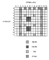
- FIG. 2 shows an example of a resource mapping pattern of a reference signal in NR (New Radio) (see Non-Patent Document 1).
- DM-RS DeModulation RS
- CSI-RS Channel State Information RS
- TRS Track RS
- PT-RS Phase Tracking RS
- FIG. 3 is a conceptual diagram for explaining the setting of the resource mapping pattern MP in the present embodiment.
- the first wireless communication system 10-1 uses the "first resource mapping pattern MP-1" as the resource mapping pattern MP of the specific signal to perform wireless communication.
- the second wireless communication system 10-2 uses the "second resource mapping pattern MP-2" as the resource mapping pattern MP of the specific signal to perform wireless communication.
- the first resource mapping pattern MP-1 and the second resource mapping pattern MP-2 are set to match each other.
- the resource mapping pattern MP is uniquely defined for each country or region.
- the first wireless communication system 10-1 and the second wireless communication system 10-2 may cooperate to match the first resource mapping pattern MP-1 and the second resource mapping pattern MP-2. ..
- the subcarrier intervals of the first wireless communication system 10-1 and the second wireless communication system 10-2 are also the same. Further, the first wireless communication system 10-1 and the second wireless communication system 10-2 are time-synchronized.
- Series seed control Radio wave interference may occur between the adjacent first wireless communication system 10-1 and the second wireless communication system 10-2, either mutually or unilaterally. Therefore, when the first resource mapping pattern MP-1 and the second resource mapping pattern MP-2 match, the specific signals of the first wireless communication system 10-1 and the second wireless communication system 10-2 collide with each other. , It can be difficult to separate them. Deterioration of a specific signal causes deterioration of communication quality.
- the accuracy of channel estimation based on the reference signal deteriorates.
- the synchronization signal for initial access deteriorates and the detection probability of the synchronization signal decreases, the probability of initial access decreases.
- serial seed control is performed in order to facilitate separation of the specific signals of the first wireless communication system 10-1 and the second wireless communication system 10-2.
- the “series seed control” according to the present embodiment will be described with reference to FIG.
- the first wireless communication system 10-1 uses the "first seed SD-1" as a seed for a specific signal. That is, the first wireless communication system 10-1 generates a specific signal based on the first seed SD-1.
- the second wireless communication system 10-2 uses the "second seed SD-2" as a seed for a specific signal. That is, the second wireless communication system 10-2 generates a specific signal based on the second seed SD-2.
- the first seed SD-1 and the second seed SD-2 are set so as to be different from each other.
- a plurality of seed candidate SDSs different from each other are predetermined.
- the first seed SD-1 and the second seed SD-2 are selected from the predetermined seed candidate SDS so as to be different from each other.
- the sequence seed control is executed by at least one of the first wireless communication system 10-1 and the second wireless communication system 10-2. Both the first radio communication system 10-1 and the second radio communication system 10-2 may execute the sequence seed control.
- sequence seed control Various examples can be considered as specific methods for sequence seed control. Various examples of sequence seed control will be described later.
- the first wireless communication system 10-1 that performs wireless communication in the first cell 30-1 generates a specific signal based on the first seed SD-1, and the first resource mapping pattern.
- MP-1 is used as a resource mapping pattern MP for a specific signal.
- the second wireless communication system 10-2, which performs wireless communication in the second cell 30-2 adjacent to the first cell 30-1, generates a specific signal based on the second seed SD-2 and has a second resource mapping pattern.
- MP-2 is used as the resource mapping pattern MP for a specific signal.
- the first resource mapping pattern MP-1 and the second resource mapping pattern MP-2 match.
- the first seed SD-1 and the second seed SD-2 are set so as to be different from each other by the sequence seed control. Therefore, it is possible to separate the specific signals of the first wireless communication system 10-1 and the second wireless communication system 10-2. In other words, the interference immunity of a specific signal is improved. As a result, deterioration of communication quality is suppressed.
- This embodiment is useful for, for example, a local 5G (L5G) system.
- L5G local 5G
- FIG. 4 is a conceptual diagram for explaining a configuration example of the wireless communication system 10 according to the present embodiment.
- Each wireless communication system 10 includes a control device 100 in addition to the base station 20.
- the first wireless communication system 10-1 includes a first control device 100-1 in addition to a first base station 20-1 that performs wireless communication in the first cell 30-1.
- the first control device 100-1 performs sequence seed control and sets the first seed SD-1. Further, the first control device 100-1 sets the first resource mapping pattern MP-1 as necessary.
- the first base station 20-1 generates a specific signal based on the first seed SD-1 set by the first control device 100-1. Then, the first base station 20-1 uses the first resource mapping pattern MP-1 as the resource mapping pattern MP of the specific signal to perform wireless communication.
- the second wireless communication system 10-2 includes a second control device 100-2 in addition to the second base station 20-2 that performs wireless communication in the second cell 30-2.
- the second control device 100-2 performs sequence seed control and sets the second seed SD-2. Further, the second control device 100-2 sets the second resource mapping pattern MP-2 as necessary.
- the second base station 20-2 generates a specific signal based on the second seed SD-2 set by the second control device 100-2. Then, the second base station 20-2 uses the second resource mapping pattern MP-2 as the resource mapping pattern MP of the specific signal to perform wireless communication.
- the position and connection form of the control device 100 are not particularly limited.
- the control device 100 may be included in the core unit or may be included in the base station control unit.
- the control device 100 may be arranged in the vicinity of the base station 20 or may be arranged at a position away from the base station 20 via a network.
- the control device 100 and the base station 20 are preferably connected by wire.
- the control device 100 and the base station 20 may be wirelessly connected.
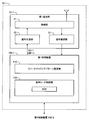
- FIG. 5 is a block diagram showing a functional configuration example of the wireless communication system 10 according to the present embodiment.
- FIG. 5 shows, as a representative, an example of the functional configuration of the first wireless communication system 10-1. The same applies to the second wireless communication system 10-2.
- the first base station 20-1 includes a radio unit 21, a signal generation unit 22, and a signal demodulation unit 23.
- the radio unit 21 transmits and receives radio signals.
- the signal generation unit 22 generates a transmission signal.
- the transmission signal includes a specific signal such as a synchronization signal and a reference signal.
- the signal generation unit 22 generates a specific signal based on the first seed SD-1. Further, the signal generation unit 22 generates a transmission signal including a specific signal mapped according to the first resource mapping pattern MP-1. Then, the signal generation unit 22 outputs the transmission signal to the radio unit 21.
- the signal demodulation unit 23 demodulates the radio signal received by the radio unit 21.
- the signal demodulation unit 23 sends the received signal to the first control device 100-1 as needed.
- the first control device 100-1 includes a resource mapping pattern setting unit 110 and a series seed control unit 120.
- the resource mapping pattern setting unit 110 determines the first resource mapping pattern MP-1 to be used. Then, the resource mapping pattern setting unit 110 notifies the signal generation unit 22 of the first base station 20-1 of the first resource mapping pattern MP-1. When the first base station 20-1 holds the resource mapping pattern MP uniquely defined for each country or region, the resource mapping pattern setting unit 110 may be omitted.
- the series seed control unit 120 executes the series seed control. For example, the sequence seed control unit 120 holds a plurality of seed candidate SDSs that are different from each other. A plurality of seed candidate SDSs are predetermined. The series seed control unit 120 determines the first seed SD-1 to be used from the predetermined seed candidate SDS. Then, the sequence seed control unit 120 notifies the signal generation unit 22 of the first base station 20-1 of the first seed SD-1. Various examples of sequence seed control will be described later.
- the first control device 100-1 may communicate with the second control device 100-2.
- the first control device 100-1 and the second control device 100-2 are connected via a dedicated line.
- the first control device 100-1 and the second control device 100-2 may perform wireless communication by IAB (Integrated Access and Backhaul).
- FIG. 6 is a block diagram showing a configuration example of the control device 100 according to the present embodiment.
- FIG. 6 shows a configuration example of the first control device 100-1 as a representative. The same applies to the second control device 100-2.
- the first control device 100-1 includes a communication device 130 and an information processing device 140.
- the communication device 130 communicates with the first base station 20-1. Further, the communication device 130 communicates with the second control device 100-2. As described above, the communication method may be wired or wireless.
- the information processing device 140 is a computer that performs various types of information processing.
- the information processing device 140 includes a processor 141 and a storage device 142.
- the processor 141 performs various information processing.
- the processor 141 includes a CPU (Central Processing Unit).
- the storage device 142 stores various information necessary for processing by the processor 141. Examples of the storage device 142 include a volatile memory, a non-volatile memory, an HDD (Hard Disk Drive), an SDD (Solid State Drive), and the like.
- the wireless communication system control program 150 is a computer program executed by a computer.
- the function of the information processing apparatus 140 is realized by the processor 141 executing the wireless communication system control program 150.
- the wireless communication system control program 150 is stored in the storage device 142.
- the wireless communication system control program 150 may be recorded on a computer-readable recording medium.
- the wireless communication system control program 150 may be provided via a network.
- the information processing device 140 may be realized by using hardware such as an ASIC (Application Specific Integrated Circuit), a PLD (Programmable Logic Device), and an FPGA (Field Programmable Gate Array).
- ASIC Application Specific Integrated Circuit
- PLD Process-Demand Device
- FPGA Field Programmable Gate Array
- the resource mapping pattern setting unit 110 and the sequence seed control unit 120 described above are realized by the communication device 130 and the information processing device 140.
- FIG. 7 is a flowchart showing processing by the wireless communication system 10 according to the present embodiment.
- the processing by the first wireless communication system 10-1 will be described.
- Step S100 the resource mapping pattern setting unit 110 of the first control device 100-1 sets the first resource mapping pattern MP-1.
- the resource mapping pattern setting unit 110 sets the first resource mapping pattern MP-1 so as to match the second resource mapping pattern MP-2.
- the setting method of the first resource mapping pattern MP-1 will be described.
- the resource mapping pattern MP is uniquely defined for each country or region.
- the resource mapping pattern setting unit 110 holds a uniquely defined resource mapping pattern MP.
- the resource mapping pattern setting unit 110 notifies the first base station 20-1 of the resource mapping pattern MP as the first resource mapping pattern MP-1. If the first base station 20-1 holds the resource mapping pattern MP in advance, step S100 may be omitted.
- FIG. 8 is a flowchart showing a second example of step S100.
- step S120 the resource mapping pattern setting unit 110 receives the notification of the "second resource mapping pattern MP-2" from the second control device 100-2 of the second wireless communication system 10-2.
- step S121 the resource mapping pattern setting unit 110 notifies the first base station 20-1 of the second resource mapping pattern MP-2 as the first resource mapping pattern MP-1. In this way, the first resource mapping pattern MP-1 and the second resource mapping pattern MP-2 can be reliably matched.
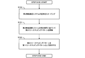
- FIG. 9 is a flowchart showing a third example of step S100.
- the first base station 20-1 receives (snooping) a signal transmitted from the second base station 20-2 of the second wireless communication system 10-2.
- the signal demodulation unit 23 of the first base station 20-1 notifies the resource mapping pattern setting unit 110 of the received signal.
- the signal demodulation unit 23 notifies the resource mapping pattern setting unit 110 of the specific signal included in the received signal.
- step S131 the resource mapping pattern setting unit 110 recognizes the second resource mapping pattern MP-2 used in the second wireless communication system 10-2 based on the specific signal included in the received signal.
- step S132 the resource mapping pattern setting unit 110 notifies the first base station 20-1 of the second resource mapping pattern MP-2 as the first resource mapping pattern MP-1. In this way, the first resource mapping pattern MP-1 and the second resource mapping pattern MP-2 can be matched.
- the first control device 100-1 can set the first resource mapping pattern MP-1 by itself without receiving a notification from the second control device 100-2.
- step S200 the sequence seed control unit 120 of the first control device 100-1 performs sequence seed control. Specifically, the series seed control unit 120 sets the first seed SD-1 so as to be different from the second seed SD-2. Then, the sequence seed control unit 120 notifies the first base station 20-1 of the first seed SD-1.
- step S200 various examples of series seed control
- FIG. 10 is a flowchart showing a first example of series seed control (step S200).
- step S210 the sequence seed control unit 120 receives the notification of the "selectable candidate" from the second control device 100-2 of the second wireless communication system 10-2.
- the selectable candidates include at least one seed candidate different from the second seed SD-2.
- the second control device 100-2 holds a predetermined seed candidate SDS as in the first control device 100-1.
- the second control device 100-2 can generate selectable candidates based on the second seed SD-2 used and the predetermined seed candidate SDS.
- the second control device 100-2 may periodically notify the selectable candidates.
- step S211 the series seed control unit 120 selects the first seed SD-1 from the received selectable candidates.
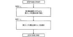
- FIG. 11 is a flowchart showing a second example of sequence seed control (step S200).
- the second example is a modification of the first example.
- step S220 the series seed control unit 120 receives the notification of "second seed SD-2" from the second control device 100-2 of the second wireless communication system 10-2.
- step S221 the sequence seed control unit 120 selects the first seed SD-1 different from the second seed SD-2 from the predetermined seed candidate SDSs.
- FIG. 12 is a flowchart showing a third example of sequence seed control (step S200).
- the first base station 20-1 receives (snooping) a signal transmitted from the second base station 20-2 of the second wireless communication system 10-2.
- the signal demodulation unit 23 of the first base station 20-1 notifies the series seed control unit 120 of the received signal.
- the signal demodulation unit 23 notifies the series seed control unit 120 of the specific signal included in the received signal.
- step S130 and step S230 may be shared.
- step S231 the sequence seed control unit 120 recognizes the second seed SD-2 used in the second radio communication system 10-2 based on the specific signal included in the received signal.
- step S232 the sequence seed control unit 120 selects the first seed SD-1 different from the second seed SD-2 from the predetermined seed candidate SDSs.
- the first control device 100-1 can set the first seed SD-1 by itself without receiving a notification from the second control device 100-2.
- FIG. 13 is a flowchart showing a fourth example of series seed control (step S200). The processing flow shown in FIG. 13 is executed periodically.
- step S240 the series seed control unit 120 changes the first seed SD-1 to be used. That is, the series seed control unit 120 selects a predetermined seed candidate SDS different from the previous one.
- the first base station 20-1 performs wireless communication using the first seed SD-1 set in step S240. Further, the first base station 20-1 measures and records the communication quality. Examples of parameters representing communication quality include SIR (Signal to Interference power Ratio) and the like. The first base station 20-1 notifies the series seed control unit 120 of the communication quality.
- step S243 the sequence seed control unit 120 determines whether or not the communication quality is good. For example, the sequence seed control unit 120 determines whether or not the communication quality is at a certain level or higher. If the communication quality is less than a certain level (step S243; No), the process returns to step S240. On the other hand, when the communication quality is equal to or higher than a certain level (step S243; Yes), the process proceeds to step S244.
- the series seed control unit 120 determines whether or not the communication quality is the highest quality. If the communication quality is not the highest quality (step S243; No), the process returns to step S240. On the other hand, when the communication quality is the highest quality (step S243; Yes), the process proceeds to step S244.
- step S244 the sequence seed control unit 120 determines what is selected in step S240 as the first seed SD-1.
- the first seed SD-1 is periodically changed in the predetermined seed candidate SDS. In other words, hopping of the first seed SD-1 is performed. Although there is a slight possibility that the first seed SD-1 and the second seed SD-2 may temporarily overlap, the first seed SD-1 is generally set to be different from the second seed SD-2. In particular, the first seed SD-1 from which good communication quality can be obtained is considered to be different from the second seed SD-2. Therefore, the effect according to the present embodiment can be obtained.
- FIG. 14 is a flowchart showing a fifth example of sequence seed control (step S200).
- the fifth example is a modification of the fourth example.
- the setting of the first resource mapping pattern MP-1 (step S100) is also performed at the same time.
- Step S240 is the same as in the case of the fourth example.
- the resource mapping pattern setting unit 110 changes the first resource mapping pattern MP-1. For example, a plurality of resource mapping pattern candidates that do not overlap each other are predetermined. The resource mapping pattern setting unit 110 selects a predetermined resource mapping pattern candidate different from the previous one from the predetermined resource mapping pattern candidates.
- step S242 the first base station 20-1 performs wireless communication using the first seed SD-1 set in step S240 and the first resource mapping pattern MP-1 set in step S241.
- the first base station 20-1 measures the communication quality and notifies the series seed control unit 120 of the communication quality.
- step S243 If the communication quality is not good (step S243; No), the process returns to step S240. On the other hand, when the communication quality is good (step S243; Yes), the process proceeds to step S245.
- step S245 the sequence seed control unit 120 determines what is selected in step S240 as the first seed SD-1. Further, the resource mapping pattern setting unit 110 determines what is selected in step S241 as the first resource mapping pattern MP-1. That is, the sequence seed control unit 120 determines the combination of the first seed SD-1 and the first resource mapping pattern MP-1.
- hopping of the first resource mapping pattern MP-1 is also performed. Even if the second resource mapping pattern MP-2 changes, the first resource mapping pattern MP-1 and the second resource can be obtained by searching for the first resource mapping pattern MP-1 that can obtain good communication quality. The probability that the mapping pattern MP-2 matches is increased. The predetermined resource mapping pattern candidates may be further narrowed down from those specified in the standard. As a result, the probability that the first resource mapping pattern MP-1 and the second resource mapping pattern MP-2 match can be further increased.
- Step S300 the first base station 20-1 performs wireless communication using the first seed SD-1 and the first resource mapping pattern MP-1. Specifically, the signal generation unit 22 generates a specific signal based on the first seed SD-1. Further, the signal generation unit 22 generates a transmission signal including a specific signal mapped according to the first resource mapping pattern MP-1. Then, the signal generation unit 22 outputs the transmission signal to the radio unit 21. The radio unit 21 transmits a transmission signal.
- 10 ... Wireless communication system 10-1 ... 1st wireless communication system, 10-2 ... 2nd wireless communication system, 20 ... Base station, 20-1 ... 1st base station, 20-2 ... 2nd base station, 21 ... Radio unit, 22 ... Signal generation unit, 23 ... Signal demodulator, 30 ... Cell, 30-1 ... 1st cell, 30-2 ... 2nd cell, 100 ... Control device, 100-1 ... 1st control device, 100-2 ... 2nd control device, 110 ... Resource mapping pattern setting unit, 120 ... Series seed control unit, 130 ... Communication device, 140 ... Information processing device, 141 ... Processor, 142 ... Storage device, 150 ... Wireless communication system control Program, MP-1 ... 1st resource mapping pattern, MP-2 ... 2nd resource mapping pattern, SD-1 ... 1st seed, SD-2 ... 2nd seed
Landscapes
- Engineering & Computer Science (AREA)
- Signal Processing (AREA)
- Computer Networks & Wireless Communication (AREA)
- Mobile Radio Communication Systems (AREA)
Abstract
Priority Applications (3)
| Application Number | Priority Date | Filing Date | Title |
|---|---|---|---|
| JP2022531116A JP7416242B2 (ja) | 2020-06-15 | 2020-06-15 | 無線通信システム、無線通信システムの制御方法、無線通信システムの制御装置、及び無線通信システム制御プログラム |
| PCT/JP2020/023452 WO2021255794A1 (fr) | 2020-06-15 | 2020-06-15 | Système de communication sans fil, procédé, dispositif et programme de commande pour système de communication sans fil |
| US18/010,038 US12317144B2 (en) | 2020-06-15 | 2020-06-15 | Radio communication system, control method and control device for radio communication system, and radio communication system control program |
Applications Claiming Priority (1)
| Application Number | Priority Date | Filing Date | Title |
|---|---|---|---|
| PCT/JP2020/023452 WO2021255794A1 (fr) | 2020-06-15 | 2020-06-15 | Système de communication sans fil, procédé, dispositif et programme de commande pour système de communication sans fil |
Publications (1)
| Publication Number | Publication Date |
|---|---|
| WO2021255794A1 true WO2021255794A1 (fr) | 2021-12-23 |
Family
ID=79268654
Family Applications (1)
| Application Number | Title | Priority Date | Filing Date |
|---|---|---|---|
| PCT/JP2020/023452 Ceased WO2021255794A1 (fr) | 2020-06-15 | 2020-06-15 | Système de communication sans fil, procédé, dispositif et programme de commande pour système de communication sans fil |
Country Status (3)
| Country | Link |
|---|---|
| US (1) | US12317144B2 (fr) |
| JP (1) | JP7416242B2 (fr) |
| WO (1) | WO2021255794A1 (fr) |
Citations (2)
| Publication number | Priority date | Publication date | Assignee | Title |
|---|---|---|---|---|
| JP2014523718A (ja) * | 2011-07-15 | 2014-09-11 | パナソニック インテレクチュアル プロパティ コーポレーション オブ アメリカ | 送信装置、送信方法、及び集積回路 |
| WO2016002323A1 (fr) * | 2014-07-01 | 2016-01-07 | 株式会社Nttドコモ | Station de base, terminal utilisateur, système de communication sans fil et procédé de commande de communication |
Family Cites Families (71)
| Publication number | Priority date | Publication date | Assignee | Title |
|---|---|---|---|---|
| KR950700653A (ko) * | 1993-01-13 | 1995-01-16 | 존 에이취, 무어 | 시퀀스의 재사용을 이용하는 코드 분할 다중 접속(CDMA) 내향 메세지 전달 시스템(Code Division Multiple Access(CDMA) Inbound Messaging System Utilizing Re-Use of Sequences) |
| KR20090131545A (ko) * | 2008-06-18 | 2009-12-29 | 한국전자통신연구원 | 셀룰러 시스템에서 셀 계획이 필요 없는 셀 간 간섭 관리방법 |
| JP5189460B2 (ja) * | 2008-10-30 | 2013-04-24 | 株式会社エヌ・ティ・ティ・ドコモ | 移動通信システムにおける基地局装置、ユーザ装置及び方法 |
| US8311005B2 (en) * | 2008-11-13 | 2012-11-13 | Nec Laboratories America, Inc. | Methods and systems for allocation of macro cell resources in a distributed femto cell network and a distributed relay station network |
| CN101873629A (zh) * | 2009-04-24 | 2010-10-27 | 北京三星通信技术研究有限公司 | 一种多点联合传输的方法和装置 |
| US8787304B2 (en) * | 2010-06-22 | 2014-07-22 | Acer Incorporated | Method for reference signal pattern allocation and related communication device |
| US8831119B2 (en) * | 2010-06-28 | 2014-09-09 | Lg Electronics Inc. | Method and apparatus for transmitting synchronization signal in multi-node system |
| EP3021505A1 (fr) * | 2011-01-10 | 2016-05-18 | LG Electronics, Inc. | Procede et dispositif de transmission/reception de signal de reference de liaison descendante dans un systeme de communication sans fil |
| JP6106079B2 (ja) * | 2011-03-31 | 2017-03-29 | パナソニック インテレクチュアル プロパティ コーポレーション オブ アメリカPanasonic Intellectual Property Corporation of America | 送信装置、受信装置、送信方法、及び受信方法 |
| US10638464B2 (en) * | 2011-04-01 | 2020-04-28 | Futurewei Technologies, Inc. | System and method for transmission and reception of control channels in a communications system |
| US11671947B2 (en) * | 2011-07-15 | 2023-06-06 | Sun Patent Trust | Reception apparatus and reception method |
| TWI474638B (zh) * | 2011-11-08 | 2015-02-21 | Realtek Semiconductor Corp | 消除傳輸埠間干擾之網路裝置及其消除傳輸埠間干擾之方法 |
| JP5893205B2 (ja) * | 2012-03-28 | 2016-03-23 | ノキア テクノロジーズ オーユー | ポータブル・ロング・ターム・エボリューション・ローカル・エリア・ネットワーク間干渉に関わるセル間干渉検出 |
| CN104303439B (zh) * | 2012-05-30 | 2017-10-13 | 英特尔公司 | 用于管理异构载波类型的技术 |
| KR101961919B1 (ko) * | 2012-06-09 | 2019-03-27 | 삼성전자주식회사 | 무선 통신 시스템에서 신호 송수신 방법 및 장치 |
| JP6033601B2 (ja) * | 2012-08-07 | 2016-11-30 | 株式会社Nttドコモ | 干渉低減方法、無線基地局、ユーザ端末及び無線通信システム |
| CA2886214C (fr) * | 2012-09-28 | 2017-10-24 | Blackberry Limited | Procedes et appareil pour permettre des ameliorations apportees a des sous-trames flexibles dans des reseaux heterogenes lte |
| JP6121124B2 (ja) * | 2012-09-28 | 2017-04-26 | 株式会社Nttドコモ | 無線通信システム、無線通信方法、ユーザ端末及び無線基地局 |
| JP6243435B2 (ja) * | 2012-10-18 | 2017-12-06 | エルジー エレクトロニクス インコーポレイティド | 無線通信システムにおいて下りリンク制御信号を受信又は送信するための方法及びそのための装置 |
| US9407302B2 (en) * | 2012-12-03 | 2016-08-02 | Intel Corporation | Communication device, mobile terminal, method for requesting information and method for providing information |
| US10171225B2 (en) * | 2013-04-01 | 2019-01-01 | Panasonic Intellectual Property Corporation Of America | Communication apparatus and control signal mapping method |
| EP2992715B1 (fr) * | 2013-05-03 | 2021-07-14 | BlackBerry Limited | Transmission d'une indication de synchronisation |
| US10165455B2 (en) * | 2013-08-22 | 2018-12-25 | Telefonaktiebolaget Lm Ericsson (Publ) | Coordination for PBCH |
| JP6571107B2 (ja) * | 2014-04-14 | 2019-09-04 | エルジー エレクトロニクス インコーポレイティド | 無線通信システムにおいて端末間直接通信のための同期信号伝送方法及びそのための装置 |
| US9867083B2 (en) * | 2014-04-17 | 2018-01-09 | Cisco Technology, Inc. | Wireless network controller load balancing |
| JP6419846B2 (ja) * | 2014-04-29 | 2018-11-07 | エルジー エレクトロニクス インコーポレイティド | 無線通信システムにおいて装置対装置端末のデータ伝送方法及び装置 |
| DE102015209441A1 (de) * | 2014-05-23 | 2015-12-10 | Samsung Electronics Co., Ltd. | Schema zum Senden eines Referenzsignals in einem drahtlosen Kommunikationssystem |
| US10278117B2 (en) * | 2015-04-29 | 2019-04-30 | Blackberry Limited | Randomized beacon transmissions |
| US20180091277A1 (en) * | 2015-05-08 | 2018-03-29 | Intel Corporation | Scrambling and modulation of channel state information reference signals (csi-rs) for full-dimensional multiple-input-multiple-output (fd-mimo) systems |
| WO2016182601A1 (fr) * | 2015-05-14 | 2016-11-17 | Intel Corporation | Réduction de signalisation simultanée dans un équipement utilisateur (ue) relais |
| GB2540593A (en) * | 2015-07-22 | 2017-01-25 | Sony Corp | Receiver and method of receiving |
| WO2017037505A1 (fr) * | 2015-08-31 | 2017-03-09 | Telefonaktiebolaget Lm Ericsson (Publ) | Configuration de signal de référence pour la coordination cellulaire |
| EP3840279A1 (fr) * | 2016-02-17 | 2021-06-23 | Samsung Electronics Co., Ltd. | Procédé et dispositif pour réaliser une communication dans un système de communication sans fil |
| JP2019519952A (ja) * | 2016-04-15 | 2019-07-11 | テレフオンアクチーボラゲット エルエム エリクソン(パブル) | 無線ネットワークノード、無線デバイス及びそれらにおいて実行される方法 |
| KR102511694B1 (ko) * | 2016-07-13 | 2023-03-20 | 삼성전자 주식회사 | 무선 통신 시스템에서 슬라이딩 윈도우 중첩 코딩 전송을 위한 시그널링 방법 및 장치 |
| CN107645370B (zh) * | 2016-07-20 | 2020-12-08 | 华为技术有限公司 | 资源映射方法和装置 |
| US10764020B2 (en) * | 2016-07-26 | 2020-09-01 | Lg Electronics Inc. | Uplink signal transmission method and user equipment, and uplink signal reception method and base station |
| WO2018027222A1 (fr) * | 2016-08-05 | 2018-02-08 | Intel IP Corporation | Transmission de signaux de référence de suivi de phase (pt-rs) |
| CN109804687B (zh) * | 2016-08-10 | 2023-05-02 | 株式会社Ntt都科摩 | 用户终端以及无线通信方法 |
| US10645689B2 (en) * | 2016-08-11 | 2020-05-05 | Qualcomm Incorporated | Link establishment in a wireless backhaul network using radio access technology |
| WO2018030867A1 (fr) * | 2016-08-11 | 2018-02-15 | 삼성전자 주식회사 | Procédé de commande de sélection et de resélection de cellule en fonction d'un service |
| US10396926B2 (en) * | 2016-08-19 | 2019-08-27 | Samsung Electronics Co., Ltd. | Apparatus and method for suppressing inter-cell interference in wireless communication system |
| JP6877452B2 (ja) * | 2016-09-28 | 2021-05-26 | パナソニック インテレクチュアル プロパティ コーポレーション オブ アメリカPanasonic Intellectual Property Corporation of America | 無線送信装置、無線受信装置、送信方法及び受信方法 |
| US11252730B2 (en) * | 2016-10-26 | 2022-02-15 | Lg Electronics Inc. | Method for performing beam management in wireless communication system and apparatus therefor |
| WO2018144269A1 (fr) * | 2017-02-02 | 2018-08-09 | Intel Corporation | Atténuation d'interférence de crs lte assistée par réseau |
| US11019584B2 (en) * | 2017-03-14 | 2021-05-25 | Qualcomm Incorporated | User equipment operation in bandwidth narrower than synchronization signal bandwidth |
| US10833822B2 (en) * | 2017-04-24 | 2020-11-10 | Huawei Technologies Co., Ltd. | System and method for MA signature assignment based on UE group separation |
| WO2018203395A1 (fr) * | 2017-05-02 | 2018-11-08 | 株式会社Nttドコモ | Terminal d'utilisateur, station de base sans fil et procédé de communication sans fil |
| CN109041105B (zh) * | 2017-06-09 | 2020-10-16 | 维沃移动通信有限公司 | 邻小区信息的发送方法、邻小区信息的处理方法及设备 |
| US11252683B2 (en) * | 2017-06-15 | 2022-02-15 | Ntt Docomo, Inc. | User terminal and radio communication method |
| US11051263B2 (en) * | 2017-06-15 | 2021-06-29 | Qualcomm Incorporated | Synchronization channel and system acquisition for internet of things communications in a shared spectrum |
| US10862606B2 (en) * | 2017-06-16 | 2020-12-08 | Qualcomm Incorporated | Signaling and using virtual cell identification for SFN-type transmissions |
| US11445483B2 (en) * | 2017-08-01 | 2022-09-13 | Qualcomm Incorporated | Uplink control channel resource definition and mapping to user equipment |
| US20190149298A1 (en) * | 2017-11-15 | 2019-05-16 | Mediatek Inc. | Reference Signals With Improved Cross-Correlation Properties In Wireless Communications |
| WO2019160652A1 (fr) * | 2018-02-15 | 2019-08-22 | Sony Corporation | Procédé et appareil de mise en correspondance d'un motif de faisceau sur des ressources de radiorecherche |
| US11540257B2 (en) * | 2018-03-23 | 2022-12-27 | Qualcomm Incorporated | Uplink control information transmission on autonomous uplink in new radio-unlicensed (NR-U) |
| US11108526B2 (en) * | 2018-04-02 | 2021-08-31 | Qualcomm Incorporated | Channel quality indicator (CQI) reporting for ultra-reliable low latency communications (URLLC) |
| US11005623B2 (en) * | 2018-04-23 | 2021-05-11 | Qualcomm Incorporated | Demodulation reference signal configuration for shortened transmission time interval baseline pattern |
| US11095482B2 (en) * | 2018-04-30 | 2021-08-17 | Apple Inc. | Channel state information reference signal (CSI-RS) and sounding reference signal (SRS) triggering |
| US10999810B2 (en) * | 2018-07-09 | 2021-05-04 | Qualcomm Incorporated | Physical random access channel (PRACH) configuration periodicity extension for backhaul links |
| CN110881220B (zh) * | 2018-09-06 | 2022-09-30 | 大唐移动通信设备有限公司 | 多传输点trp数据处理的方法、基站、终端及存储介质 |
| US12407397B2 (en) * | 2018-09-18 | 2025-09-02 | Nec Corporation | Multi-TRP transmission |
| US11297621B2 (en) * | 2018-11-02 | 2022-04-05 | Qualcomm Incorporated | Cyclic prefix orthogonal frequency division multiplexing sequence configuration of a downlink / uplink |
| US11979912B2 (en) * | 2019-02-07 | 2024-05-07 | Qualcomm Incorporated | Signaling of transmission parameters |
| CN111787615A (zh) * | 2019-04-04 | 2020-10-16 | 北京三星通信技术研究有限公司 | 竞争性上行数据传输的方法、ue、基站、设备及介质 |
| US12101771B2 (en) * | 2019-07-18 | 2024-09-24 | Ntt Docomo, Inc. | Terminal and radio communication method for suppressing deterioration of communication quality |
| US11178691B2 (en) * | 2019-09-09 | 2021-11-16 | Huawei Technologies Co., Ltd. | Systems and methods for sensing in half duplex networks |
| US11184901B2 (en) * | 2019-12-19 | 2021-11-23 | Telefonaktiebolaget Lm Ericsson (Publ) | Beam management |
| WO2021212286A1 (fr) * | 2020-04-20 | 2021-10-28 | 北京小米移动软件有限公司 | Procédé et appareil de transmission de canal de commande de liaison descendante physique, et support d'informations |
| EP4147405A1 (fr) * | 2020-05-06 | 2023-03-15 | Telefonaktiebolaget Lm Ericsson (Publ) | Blocage de csi-rs nzp indépendamment du port |
| US11758572B2 (en) * | 2020-06-04 | 2023-09-12 | Qualcomm Incorporated | Demodulation reference signal configuration selection and reporting per sub-band |
-
2020
- 2020-06-15 WO PCT/JP2020/023452 patent/WO2021255794A1/fr not_active Ceased
- 2020-06-15 US US18/010,038 patent/US12317144B2/en active Active
- 2020-06-15 JP JP2022531116A patent/JP7416242B2/ja active Active
Patent Citations (2)
| Publication number | Priority date | Publication date | Assignee | Title |
|---|---|---|---|---|
| JP2014523718A (ja) * | 2011-07-15 | 2014-09-11 | パナソニック インテレクチュアル プロパティ コーポレーション オブ アメリカ | 送信装置、送信方法、及び集積回路 |
| WO2016002323A1 (fr) * | 2014-07-01 | 2016-01-07 | 株式会社Nttドコモ | Station de base, terminal utilisateur, système de communication sans fil et procédé de commande de communication |
Also Published As
| Publication number | Publication date |
|---|---|
| JP7416242B2 (ja) | 2024-01-17 |
| JPWO2021255794A1 (fr) | 2021-12-23 |
| US12317144B2 (en) | 2025-05-27 |
| US20230232288A1 (en) | 2023-07-20 |
Similar Documents
| Publication | Publication Date | Title |
|---|---|---|
| KR102826102B1 (ko) | 무선 통신 시스템에서의 디바이스 및 방법, 및 컴퓨터-판독가능 저장 매체 | |
| CN113016152B (zh) | 对具有多个协调器的无线光学网络进行无干扰调度 | |
| KR101124188B1 (ko) | 복합 비컨 및 광대역 동기화 시그널링과 관련된 방법 및 장치 | |
| US9179320B2 (en) | Method for assigning and managing reference signals in a multi-cell environment, and network device and terminal for applying the method | |
| US9955440B2 (en) | Jointly managed access point transmit power control | |
| US20180124785A1 (en) | Channel Structure for Communication in Wireless Networks | |
| BRPI0620965A2 (pt) | aparelho e método para controlar comutação de canal em redes sem fio | |
| AU2008350547A1 (en) | Method and apparatus for providing carrier indication and carrier sensing in a wireless network | |
| WO2011097770A1 (fr) | Synchronisation dans un système de communication | |
| CN104412647B (zh) | 用于帮助解决通信系统中的边界问题的集群优化的方法 | |
| JP2012509615A (ja) | 中継通信方法および機器 | |
| JP6517299B2 (ja) | HetNet配置における座標インディケータの使用 | |
| JP7416242B2 (ja) | 無線通信システム、無線通信システムの制御方法、無線通信システムの制御装置、及び無線通信システム制御プログラム | |
| EP2896258A1 (fr) | Système et procédé d'identification et de gestion des chevauchements dans l'utilisation du spectre | |
| JP7601305B2 (ja) | ニューラジオ・ネットワークのための干渉防止方法 | |
| JP7424485B2 (ja) | 無線通信システム、無線通信システムの制御方法、無線通信システムの制御装置、及び無線通信システム制御プログラム | |
| EP3454619A1 (fr) | Procédé et système pour établir une communication entre des n uds de nuage d'antenne dans un réseau intérieur de haute densité | |
| JP6461929B2 (ja) | 異機種無線ネットワークにおけるディスカバリシグナル | |
| Amoah et al. | Decentralized neighborhood discovery and management in dense RFID systems | |
| WO2011012067A1 (fr) | Procédé de traitement de brouillage de station de base domestique | |
| JPWO2020129634A1 (ja) | 送信装置および送信方法、並びに受信装置および受信方法 | |
| JP6913738B2 (ja) | データ伝送の方法及び装置 | |
| CN108112047B (zh) | 以用户为中心的半动态分簇方法 | |
| TW202446014A (zh) | 進行窄頻物聯網通訊的使用者設備及其操作方法 | |
| WO2024029350A1 (fr) | Terminal d'information, dispositif de communication et procédé de communication |
Legal Events
| Date | Code | Title | Description |
|---|---|---|---|
| 121 | Ep: the epo has been informed by wipo that ep was designated in this application |
Ref document number: 20940682 Country of ref document: EP Kind code of ref document: A1 |
|
| ENP | Entry into the national phase |
Ref document number: 2022531116 Country of ref document: JP Kind code of ref document: A |
|
| NENP | Non-entry into the national phase |
Ref country code: DE |
|
| 122 | Ep: pct application non-entry in european phase |
Ref document number: 20940682 Country of ref document: EP Kind code of ref document: A1 |
|
| WWG | Wipo information: grant in national office |
Ref document number: 18010038 Country of ref document: US |