WO2021260994A1 - 自動分析装置及び分析方法 - Google Patents
自動分析装置及び分析方法 Download PDFInfo
- Publication number
- WO2021260994A1 WO2021260994A1 PCT/JP2021/004556 JP2021004556W WO2021260994A1 WO 2021260994 A1 WO2021260994 A1 WO 2021260994A1 JP 2021004556 W JP2021004556 W JP 2021004556W WO 2021260994 A1 WO2021260994 A1 WO 2021260994A1
- Authority
- WO
- WIPO (PCT)
- Prior art keywords
- stirring
- probe
- dispensing
- container
- magnetic particles
- Prior art date
- Legal status (The legal status is an assumption and is not a legal conclusion. Google has not performed a legal analysis and makes no representation as to the accuracy of the status listed.)
- Ceased
Links
Images





Classifications
-
- G—PHYSICS
- G01—MEASURING; TESTING
- G01N—INVESTIGATING OR ANALYSING MATERIALS BY DETERMINING THEIR CHEMICAL OR PHYSICAL PROPERTIES
- G01N35/00—Automatic analysis not limited to methods or materials provided for in any single one of groups G01N1/00 - G01N33/00; Handling materials therefor
- G01N35/10—Devices for transferring samples or any liquids to, in, or from, the analysis apparatus, e.g. suction devices, injection devices
- G01N35/1002—Reagent dispensers
-
- G—PHYSICS
- G01—MEASURING; TESTING
- G01N—INVESTIGATING OR ANALYSING MATERIALS BY DETERMINING THEIR CHEMICAL OR PHYSICAL PROPERTIES
- G01N35/00—Automatic analysis not limited to methods or materials provided for in any single one of groups G01N1/00 - G01N33/00; Handling materials therefor
-
- G—PHYSICS
- G01—MEASURING; TESTING
- G01N—INVESTIGATING OR ANALYSING MATERIALS BY DETERMINING THEIR CHEMICAL OR PHYSICAL PROPERTIES
- G01N35/00—Automatic analysis not limited to methods or materials provided for in any single one of groups G01N1/00 - G01N33/00; Handling materials therefor
- G01N35/00584—Control arrangements for automatic analysers
-
- G—PHYSICS
- G01—MEASURING; TESTING
- G01N—INVESTIGATING OR ANALYSING MATERIALS BY DETERMINING THEIR CHEMICAL OR PHYSICAL PROPERTIES
- G01N35/00—Automatic analysis not limited to methods or materials provided for in any single one of groups G01N1/00 - G01N33/00; Handling materials therefor
- G01N35/0098—Automatic analysis not limited to methods or materials provided for in any single one of groups G01N1/00 - G01N33/00; Handling materials therefor involving analyte bound to insoluble magnetic carrier, e.g. using magnetic separation
-
- G—PHYSICS
- G01—MEASURING; TESTING
- G01N—INVESTIGATING OR ANALYSING MATERIALS BY DETERMINING THEIR CHEMICAL OR PHYSICAL PROPERTIES
- G01N35/00—Automatic analysis not limited to methods or materials provided for in any single one of groups G01N1/00 - G01N33/00; Handling materials therefor
- G01N35/10—Devices for transferring samples or any liquids to, in, or from, the analysis apparatus, e.g. suction devices, injection devices
-
- G—PHYSICS
- G01—MEASURING; TESTING
- G01N—INVESTIGATING OR ANALYSING MATERIALS BY DETERMINING THEIR CHEMICAL OR PHYSICAL PROPERTIES
- G01N35/00—Automatic analysis not limited to methods or materials provided for in any single one of groups G01N1/00 - G01N33/00; Handling materials therefor
- G01N2035/00465—Separating and mixing arrangements
- G01N2035/00534—Mixing by a special element, e.g. stirrer
- G01N2035/00544—Mixing by a special element, e.g. stirrer using fluid flow
-
- G—PHYSICS
- G01—MEASURING; TESTING
- G01N—INVESTIGATING OR ANALYSING MATERIALS BY DETERMINING THEIR CHEMICAL OR PHYSICAL PROPERTIES
- G01N35/00—Automatic analysis not limited to methods or materials provided for in any single one of groups G01N1/00 - G01N33/00; Handling materials therefor
- G01N2035/00465—Separating and mixing arrangements
- G01N2035/00564—Handling or washing solid phase elements, e.g. beads
- G01N2035/00574—Means for distributing beads
-
- G—PHYSICS
- G01—MEASURING; TESTING
- G01N—INVESTIGATING OR ANALYSING MATERIALS BY DETERMINING THEIR CHEMICAL OR PHYSICAL PROPERTIES
- G01N35/00—Automatic analysis not limited to methods or materials provided for in any single one of groups G01N1/00 - G01N33/00; Handling materials therefor
- G01N35/10—Devices for transferring samples or any liquids to, in, or from, the analysis apparatus, e.g. suction devices, injection devices
- G01N2035/1027—General features of the devices
- G01N2035/1048—General features of the devices using the transfer device for another function
- G01N2035/1058—General features of the devices using the transfer device for another function for mixing
- G01N2035/106—General features of the devices using the transfer device for another function for mixing by sucking and blowing
Definitions
- This disclosure relates to an automatic analyzer and an analysis method.
- An automatic analyzer, a chemical experiment device, etc. are devices that perform analysis and experiments using various reagents.
- magnetic particles are generally used as one of the reagents for separating a measurement target from other substances.
- the separation method using magnetic particles is a method in which a compound that causes a specific bond is adsorbed or bonded to the surface of the magnetic particles, and the components in the sample solution are recovered and concentrated via this compound.
- magnetic particles since magnetic particles have a large specific gravity, they have the property of gradually settling due to gravity.
- Patent Document 1 describes that an automatic analyzer stirs a liquid containing a magnetic substance in a reaction vessel using a stirring mechanism (see claim 1 of the same document).
- the present disclosure provides a technique capable of stirring a liquid containing fine particles without providing a dedicated stirring mechanism.
- the automatic analyzer of the present disclosure includes a probe for sucking and discharging a sample and a reagent, and a control unit for controlling the operation of the probe, and the control unit is placed in an empty container.
- the sample, the reagent and the fine particles are dispensed to obtain a mixed solution, and after the dispensing, the mixed solution in the container is sucked and discharged and stirred before the precipitation of the fine particles.
- the probe is controlled so as to perform the first stirring, the precipitation of the fine particles, and then the second stirring in which the mixed solution in the container is sucked and discharged and stirred.
- the flowchart which shows the analysis method which concerns on 1st Embodiment.
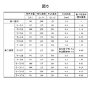
- the schematic diagram for demonstrating the operation of the 2nd stirring which concerns on 1st Embodiment. The figure which shows the value of a parameter under each stirring condition and the dispersity of a magnetic particle.
- the graph which shows the distribution of the particle density under each stirring condition.
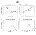
- the graph which shows the relationship between each parameter of 2nd stirring and the degree of dispersion.
- FIG. 1 is a schematic view showing an automated analyzer 100 according to the first embodiment.
- the automatic analyzer 100 includes a sample container disk 102, a reagent container disk 104, an incubator disk 105, a dispensing mechanism 106, a detection unit 107, a control device 108, a reaction container storage unit 109, and a dispensing chip storage.
- a unit 110, a disposal unit 111, a transport device 112, and a dispensing chip mounting unit 113 are provided.
- the sample container disk 102 stores a plurality of sample containers 101 for storing biological samples (hereinafter referred to as samples) such as blood and urine.
- the reagent container disk 104 contains a plurality of reagent containers 103 containing various reagents used for sample analysis.
- the incubator disc 105 contains a plurality of reaction vessels 34 for reacting the sample and the reagent.
- the dispensing mechanism 106 drives a probe (not shown in FIG. 1) provided on an arm that rotates around a rotation axis, and distributes a sample from the sample container 101 to the reaction container 34 by suction and discharge operations. Pour and dispense the reagent from the reagent vessel 103 to the reaction vessel 34.
- the detection unit 107 detects the characteristics of the reaction liquids of the sample and the reagent dispensed into the reaction vessel 34.
- the control device 108 is, for example, a computer device, and controls the operation of the entire automatic analyzer 100. Further, the control device 108 receives the detection result from the detection unit 107 and analyzes the substance to be measured in the sample.
- a plurality of unused reaction vessels 34 are stored in the reaction vessel storage unit 109.
- a plurality of unused dispensing chips 32 are stored in the dispensing chip storage unit 110. The used reaction vessel 34 and the dispensing tip 32 are discarded in the disposal unit 111.
- the transport device 112 includes an actuator that grips the reaction vessel 34 and the dispensing tip 32 and can move in the triaxial direction.
- the transport device 112 transports the reaction vessel 34 housed in the reaction vessel storage section 109 to the incubator disk 105, or transports the dispensing tip 32 stored in the dispensing tip storage section 110 to the dispensing tip mounting section 113. Or, the used reaction vessel 34 is discarded in the disposal unit 111.
- the dispensing tip 32 is mounted on the tip of the probe of the dispensing mechanism 106 at the dispensing tip mounting portion 113.
- FIG. 2 is a flowchart showing a method of analyzing a sample by the automatic analyzer 100.
- Reagents for immunoassay include an antibody that binds to the component to be measured in a sample and a label that is chemically bound to this antibody (hereinafter, simply referred to as "label"), and magnetic particles. And a biotinylated modified antibody that binds the component to be measured in the sample.
- label simply referred to as “label”
- the reagent for immunoassay is set in the reagent container disk 104 in a state of being stored in the reagent container 103.
- Magnetic particle solution a solution of magnetic particles (fine particles) coated with avidin on the surface (hereinafter, simply referred to as “magnetic particle solution”) is also set in the reagent container disk 104 in a state of being stored in the reagent container 103.
- Avidin and biotin have the property of binding extremely strongly.
- Step S1 Start analysis
- the control device 108 activates each part of the automatic analysis device 100 to start the analysis.
- the control device 108 drives the dispensing mechanism 106 and the transport device 112 to mount the dispensing tip 32 on the probe in the dispensing tip mounting portion 113.
- Step S2 1st division
- the control device 108 rotates the sample container disk 102 and moves the dispensing mechanism 106 to dispense the sample from the sample container 101 to the reaction container 34 of the incubator disk 105. Further, the control device 108 rotates the reagent container disk 104 and moves the dispensing mechanism 106 to dispense the reagent from the reagent container 103 to the reaction container 34.
- the component to be measured contained in the sample and the label bind to each other. Further, the component to be measured and the biotinylated modified antibody are bound, and the label and biotin are integrated via the component to be measured. While left unattended, it is expected that the reaction will continue due to diffusion and reach an equilibrium state. After this reaction reaches equilibrium, the next step is started.
- Step S3 2nd division
- the control device 108 rotates the reagent container disk 104 and moves the dispensing mechanism 106 to dispense the magnetic particle solution from the reagent container 103 containing the magnetic particle solution to the reaction vessel 34.
- Step S4 First stirring
- the control device 108 drives the dispensing mechanism 106 to suck and discharge the mixture of the sample, the reagent, and the magnetic particles before the precipitation of the magnetic particles, and stir.
- the stirring performed before the precipitation of the magnetic particles is referred to as the first stirring.
- the specific conditions of the first stirring will be described later.
- control device 108 rotates the dispensing mechanism 106, discards the dispensing tip 32 in the disposal unit 111, drives the transport device 112, and mounts a new dispensing tip 32 on the dispensing tip mounting unit 113.
- the dispensing tip 106 is rotated to mount a new dispensing tip 32 on the dispensing probe at the dispensing tip mounting portion 113.
- Step S5 Reaction
- the control device 108 determines whether or not the reaction between the sample and the reagent is completed after a predetermined time has elapsed from the first stirring. Here, it can be determined that the reaction is completed when the reaction time preset for each reagent or sample has elapsed. If the reaction is not completed, the process proceeds to step S6.
- the magnetic particles, the component to be measured, and the label react and bond.
- an additional reaction time of a longer time for example, an additional 9 minutes, 18 minutes, 27 minutes or 36 minutes may be required for high-sensitivity measurement.
- fine particles having a large specific gravity such as magnetic particles settle in the reaction vessel 34, so that the reactivity with the substance to be measured existing in the reaction solution decreases, and the measurement results vary. there is a possibility. Therefore, in the case of a long-term reaction, it is necessary to stir the reaction solution every predetermined time, for example, every 9 minutes.
- the stirring at predetermined time intervals is as in step S6 below.
- Step S6 Second stirring
- the control device 108 drives the dispensing mechanism 106 to suck and discharge the mixed liquid in a state where the magnetic particles are precipitated, and agitate the mixture.
- the stirring performed after the precipitation of the magnetic particles is referred to as the second stirring.
- the specific conditions of the second stirring will be described later. When the second stirring is performed a plurality of times, the stirring can be performed under the same conditions each time.
- Step S7 Measurement
- the control device 108 drives the transport device 112 to transport the reaction vessel 34 to the detection unit 107.
- the detection unit 107 measures the substance to be measured in the reaction vessel 34.
- the magnetic particles integrated with the measurement target component and the label in the reaction vessel 34 are captured by the magnet in the detection unit 107.
- the amount of light emitted by an electrochemical method is detected.
- the sample and the first reagent may be dispensed in the first dispensing, and the second reagent and the magnetic particle solution may be dispensed in the second dispensing. Further, the sample, the reagent and the magnetic particle solution may be dispensed at one time.
- the dispensing mechanism 106 has a dispensing probe 31 and a dispensing tip 32 mounted on the tip of the dispensing probe 31.
- FIG. 3A shows a state immediately after the sample and the reagent are dispensed into the reaction vessel 34 in the first dispensing and the solution containing the magnetic particles 33 is dispensed into the reaction vessel 34 in the second dispensing. ..
- the reaction solution 35 (mixed solution) is obtained by mixing the sample, the reagent and the magnetic particles. Immediately after dispensing the magnetic particles 33, the magnetic particles 33 are not dispersed in the entire reaction solution 35.
- the dispensing mechanism 106 keeps the tip of the dispensing tip 32 immersed in the reaction solution 35 and dispenses the tip 32 at a suction speed VS1 ( ⁇ L / s).
- the reaction solution 35 is sucked into the water.
- the dispensing mechanism 106 the position of the tip of the dispensing tip 32 moves the dispensing probe 31 so that the discharge position P D1.
- the discharge position P D1 can be represented by the distance between the tip of the dispensing tip 32 and the bottom surface of the reaction vessel 34 at the start of discharge.
- the dispensing mechanism 106 discharges the reaction liquid sucked into the dispensing tip 32 at the dispensing speed V D1 ( ⁇ L / s). As a result, the magnetic particles 33 are dispersed throughout the reaction solution 35. After the discharge is completed, the dispensing mechanism 106 retracts the dispensing tip 32 so that the position of the tip of the dispensing tip 32 is higher than the liquid level of the reaction liquid 35.
- FIG. 4A shows a state in which the magnetic particles 33 have settled in the reaction vessel 34 after a predetermined time has elapsed from the first stirring.
- the reaction liquid 35 is charged with a suction speed VS2 ( ⁇ L / s) while the tip of the dispensing tip 32 is immersed in the reaction liquid 35.
- the position of the dispensing tip 32 is lowered while sucking the supernatant.
- the dispensing mechanism 106 the position of the tip of the dispensing tip 32 moves the dispensing probe 31 so that the discharge position P D2.
- the dispensing mechanism 106 discharges the reaction liquid sucked into the dispensing tip 32 at the dispensing speed V D2 ( ⁇ L / s). As a result, the magnetic particles 33 are dispersed throughout the reaction solution 35. After the discharge is completed, the dispensing mechanism 106 retracts the dispensing tip 32 so that the position of the tip of the dispensing tip 32 is higher than the liquid level of the reaction liquid 35.
- the reactivity between the substance to be measured dispersed in the solution and the magnetic particles 33 can be improved.
- the variation in the measurement result can be reduced, so that the analysis accuracy can be improved.
- the operation of the first stirring and the operation of the second stirring are the same in that the reaction liquid 35 in the reaction vessel 34 is sucked and discharged, but in the second stirring, the magnetic particles 33 that have settled. Is the target of stirring, so it is difficult to disperse the settled magnetic particles 33 at the bottom of the reaction vessel 34 under the same conditions as in the first stirring. Therefore, by setting the condition of the second stirring to an appropriate condition different from the condition of the first stirring, sufficient stirring efficiency can be given to the settled magnetic particles 33.
- the settled magnetic particles 33 can be dispersed with high stirring efficiency.
- the settled magnetic particles 33 can also be dispersed by setting the discharge position P D2 in the second stirring lower than the discharge position P D1 in the first stirring, that is, a position closer to the bottom of the reaction vessel 34.
- the amount of suction AS2 of the reaction solution 35 to the dispensing tip 32 in the second stirring can be smaller than the total amount of the reaction solution 35, specifically, for example, 95% or less of the total amount of the reaction solution 35. Can be. This is because, air bubbles when the suction amount A S2 exceeds the total amount of the reaction liquid 35 also will be sucked, bubbles are mixed after discharge, because the agitation there is a possibility that no stable.
- the parameters set in this simulation were defined as the suction amount, suction speed, discharge speed and discharge position (distance between the tip of the dispensing tip and the bottom of the reaction vessel at the start of discharge).
- the diameter of the magnetic particles was set to 2.8 ⁇ m, the specific gravity was set to 1.4, and the viscosity of the solvent was set to 0.89 mPa ⁇ s.
- the total amount of the reaction solution was set to 200 ⁇ L.
- the tip diameter of the dispensing tip was set to 0.4 mm, and the internal volume was set to 368 ⁇ L.
- the amount of stirring liquid in the first stirring was set to 80 ⁇ L, while the amount of stirring liquid in the second stirring was set to 95, 140 or 190 ⁇ L.
- the discharge speed of the first stirring whereas was 125 [mu] L / s, and the discharge speed V D2 of the second stirring set to 100, 200 or 300 [mu] L / s.
- the discharge position of the first stirring was set to 2.8 mm, while the discharge position of the second stirring was set to 0.8, 3.2 or 5.6 mm. Further, the condition that the position of the tip of the dispensing tip at the end of the suction of the second stirring is 5.6 mm and the discharge position at the start of the discharge is 0.8 mm is also set.
- each layer in the reaction vessel (0 to 2 mm, 2 to 4 mm, 4 to 6 mm, 6 to 8 mm, 8 to 10 mm, 10 to 11 mm from the bottom surface of the reaction vessel, respectively).
- the standard deviation of the particle density of the region was used. For example, when the particle density of the lower layer in the reaction vessel is high and the particle density of the upper layer is low, the particle distribution is biased to the lower layer and the degree of dispersion is low.
- FIG. 5 is a diagram showing parameter values and the degree of dispersion of magnetic particles under each stirring condition.
- the standard deviations of the particle densities in cases 1 to 13 are 1.36, 1.11 and 1.84, 0.55, 1.91, 1.55, 0.60 and 0, respectively. It was 66, 1.05, 0.81, 0.24, 0.52, 0.95.
- FIG. 6 is a graph showing the distribution of particle densities in cases 1 to 13.
- the horizontal axis shows the height (mm) from the bottom surface of each layer of the reaction vessel, and the vertical axis shows the particle density (pieces / ⁇ L). The above standard deviation is calculated from the particle density of each layer shown in FIG.
- FIG. 7 (a) to 7 (d) are graphs showing the relationship between each parameter of the second stirring and the degree of dispersion.
- the horizontal axis of each graph in FIG. 7 shows each parameter of the second stirring, and the vertical axis shows the standard deviation of the particle density.
- FIG. 7A shows the relationship between the discharge rate and the degree of dispersion.
- the standard deviation of the particle density in Case 1 (discharge rate 100 ⁇ L / s) is 1.36
- the standard deviation of the particle density in Case 4 discharge rate 200 ⁇ L / s) is 1.36
- Is 0.55
- the standard deviation of the particle density in Case 8 (discharge rate 300 ⁇ L / s) is 0.66.
- the discharge speed of the second stirring is faster than the discharge speed of the first stirring (126 ⁇ L / s), for example, by setting it to 200 ⁇ L / s to 300 ⁇ L / s, the magnetic particles are placed in the reaction vessel 34. It can be more evenly dispersed throughout the reaction solution.
- the discharge rate of the second stirring it is possible to make the discharge rate of the second stirring faster than 300 ⁇ L / s, but if it is too fast, magnetic particles may easily remain in the dispensing tip, so the diameter of the dispensing tip and the reaction solution Adjust the discharge rate according to the amount.
- the discharge speed of the second stirring it is also possible to make the discharge speed of the second stirring slower than 200 ⁇ L / s under the condition that the discharge speed of the first stirring is faster than the discharge speed of the first stirring.
- FIG. 7B shows the relationship between the discharge position and the degree of dispersion.
- the standard deviation of the particle density in the case 4 (discharge position 0.8 mm) is 0.55
- the standard deviation of the particle density in the case 5 (discharge position 5.6 mm) is 1.
- the standard deviation of the particle density of the case 9 (discharge position 3.2 mm) is 1.05.
- the reaction liquid immediately after the magnetic particles are dispensed is sucked. Therefore, when the discharge position is set to a low position, the amount of the dispensing chip immersed in the reaction liquid increases, so that the reagent containing the magnetic particles on the surface is used. Adheres. As a result, the amount of magnetic particles brought out to the chip increases. Therefore, by raising the discharge position of the first stirring, it is possible to prevent the magnetic particles from adhering to the dispensing tip. On the other hand, in the second stirring, the magnetic particles are settled on the bottom surface of the reaction vessel. It is possible to give the kinetic energy of the fluid to the magnetic particles without attenuation. As a result, the stirring efficiency can be improved.
- the discharge position of the second stirring to a position lower than the discharge position of the first stirring, it is possible to uniformly disperse the magnetic particles in the entire reaction liquid in the reaction vessel.
- the distance between the tip of the dispensing tip and the bottom surface of the reaction vessel can be less than 2.8 mm, and more specifically, 0.8 mm. Can be set to be. Further, by lowering the ejection position as much as possible within the range where the tip of the dispensing tip does not come into contact with the settled magnetic particles according to the amount of the magnetic particles, the magnetic particles can be dispersed more uniformly.
- FIG. 7C shows the relationship between the amount of agitated liquid and the degree of dispersion.
- the standard deviation of the particle density in Case 4 (stirring liquid volume 95 ⁇ L) is 0.55
- the standard deviation of the particle density in Case 10 (stirring liquid volume 140 ⁇ L) is 0.81.
- the standard deviation of the particle density of Case 11 (stirring liquid volume 190 ⁇ L) is 0.24.
- the standard deviation of the particle density is smaller in the case 11 having a larger amount of suction liquid than in the case 4, and the dispersibility is better.
- the reagent containing more magnetic particles may be sucked into the dispensing tip, and the amount of magnetic particles remaining in the dispensing tip may increase. be.
- the suction amount of Case 4 is 95 ⁇ L, which is close to the suction amount of 80 ⁇ L of the first stirring, the magnetic particles are dispersed in the entire reaction vessel as shown in FIG. It can be said that even if the suction amount is small, the stirring can be sufficiently performed.
- the stirring efficiency of the second stirring can be improved by increasing the suction amount.
- the total amount of the reaction solution is set to 200 ⁇ L, while the maximum amount of the suction solution is set to 190 ⁇ L (case 11). The reason for this is to prevent the suction of air bubbles, as described above.
- FIG. 7D shows the relationship between the suction rate and the degree of dispersion.
- the standard deviation of the particle density in Case 4 (suction rate 125 ⁇ L / s) is 0.55
- the standard deviation of the particle density in Case 12 is 0. 52
- the standard deviation of the particle density of case 13 (suction rate 190 ⁇ L / s) is 0.95.
- the suction speed of the second stirring can be made slower than the suction speed of the first stirring.
- the automatic analyzer 100 uses the dispensing probe for dispensing the sample and the reagent from the first stirring immediately after mixing the magnetic particles (fine particles) and the first stirring. After a predetermined time has elapsed and the magnetic particles have settled, the second stirring is performed. In this way, the reaction solution in which the magnetic particles are precipitated can be agitated without using a dedicated stirring mechanism, so that the space and cost of the apparatus can be reduced. Further, since the reaction of the magnetic particles, the sample and the reagent can be advanced by performing the second stirring, the variation in the measurement result can be reduced and the analysis accuracy of the sample can be improved.
- the dispersibility of the magnetic particles can be improved, so that the variation in the measurement result can be further reduced.
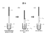
- ⁇ Analysis method> 8 (a) to 8 (c) are schematic views for explaining the operation of the second stirring according to the second embodiment.
- the present embodiment differs from the first embodiment in that a dispensing probe 81 that does not use a dispensing tip is used.
- the operation of discarding the dispensing tip and mounting a new dispensing tip after the first stirring is not executed, but instead the operation of cleaning the dispensing probe 81 in the cleaning tank containing the cleaning liquid. Is executed.
- the dispensing probe 81 can be cleaned, for example, by sucking and discharging the cleaning liquid in the cleaning tank.
- the operation is the same as that of the first embodiment, so the description thereof will be omitted.
- the conditions for the first stirring and the conditions for the second stirring in this embodiment are the same as those in the first embodiment.
- the reaction liquid 35 containing the magnetic particles 33 is stirred by using the dispensing probe 81. This eliminates the need for space for accommodating and disposing of the dispensing chips, so that the size of the apparatus can be further reduced as compared with the first embodiment.
- FIG. 9 is a schematic view showing the automated analyzer 200 according to the third embodiment.
- the automatic analyzer 200 is different from the automatic analyzer 100 (FIG. 1) of the first embodiment in that it further includes a magnetic separation device 114 for B / F separation.
- Other configurations are the same as those in the first embodiment.
- the reaction vessel 34 is transferred to the magnetic separation device 114 by the transfer device 112.
- FIG. 10A shows a state in which the reaction vessel 34 is conveyed to the magnetic separation device 114 by the transfer device 112 after the first stirring.
- a magnet 91 is arranged around a recess in which the reaction vessel 34 is housed, and magnetic particles are formed on the inner wall of the reaction vessel 34 by the magnetic field generated by the magnet 91. 33 is captured.
- the dispensing mechanism 106 sucks and removes the solution containing no magnetic particles 33 from the reaction vessel 34.
- the transfer device 112 transfers the reaction vessel 34 from the magnetic separation device 114 to the incubator disk 105.
- the dispensing mechanism 106 dispenses the cleaning liquid 92 into the reaction vessel 34.
- the magnetic particles 33 in the reaction vessel 34 are not affected by the magnetic field generated by the magnet 91, they settle on the bottom of the reaction vessel 34 and can be agitated by the suction and ejection operations by the dispensing probe 31.
- the dispensing mechanism 106 sucks the supernatant of the cleaning liquid 92 at the suction speed VS2 ( ⁇ L / s), and then discharges the discharge speed V D2 ( ⁇ L / s). ), The cleaning liquid 92 sucked into the dispensing tip 32 is discharged.
- the conditions of the suction speed VS2, the suction amount AS2 , the discharge speed VD2 , and the discharge position PD2 are the same as the conditions of the second stirring described in the first embodiment.
- the magnetic particles 33 captured by the B / F separation by the magnetic separation device 114 can be resuspended by the second stirring.
Landscapes
- Health & Medical Sciences (AREA)
- Immunology (AREA)
- Physics & Mathematics (AREA)
- Life Sciences & Earth Sciences (AREA)
- Chemical & Material Sciences (AREA)
- Analytical Chemistry (AREA)
- Biochemistry (AREA)
- General Health & Medical Sciences (AREA)
- General Physics & Mathematics (AREA)
- Pathology (AREA)
- Automatic Analysis And Handling Materials Therefor (AREA)
Abstract
Description
本明細書の記述は典型的な例示に過ぎず、本開示の特許請求の範囲又は適用例を如何なる意味に於いても限定するものではない。
<自動分析装置の構成例>
図1は、第1の実施形態に係る自動分析装置100を示す概略図である。図1に示すように、自動分析装置100は、検体容器ディスク102、試薬容器ディスク104、インキュベータディスク105、分注機構106、検出部107、制御装置108、反応容器収納部109、分注チップ収納部110、廃棄部111、搬送装置112、分注チップ装着部113を備える。
図2は、自動分析装置100による検体の分析方法を示すフローチャートである。以下においては、免疫測定方法を例として説明する。免疫測定の試薬には、検体中の測定対象成分と結合する抗体と、この抗体と化学的に結合された標識とが一体となったもの(以下、単に「標識」という)、及び、磁性粒子と検体中の測定対象成分を結合させるビオチン化修飾抗体が含まれる。自動分析装置100による分析を開始する前に、免疫測定の試薬は、試薬容器103に収納された状態で試薬容器ディスク104にセットされる。また、表面にアビジンがコーティングされた磁性粒子(微粒子)の溶液(以下、単に「磁性粒子溶液」という)も、試薬容器103に収納された状態で試薬容器ディスク104にセットされる。アビジンとビオチンは極めて強く結合する性質がある。
ステップS1において、ユーザが動作開始の指示を制御装置108に入力すると、制御装置108は自動分析装置100の各部を起動して分析を開始する。ここで、制御装置108は、分注機構106及び搬送装置112を駆動して、分注チップ装着部113においてプローブに分注チップ32を装着する。
ステップS2において、制御装置108は、検体容器ディスク102を回転させ、分注機構106を移動させて、検体容器101からインキュベータディスク105の反応容器34に検体を分注する。また、制御装置108は、試薬容器ディスク104を回転させ、分注機構106を移動させて、試薬容器103から反応容器34に試薬を分注する。
ステップS3において、制御装置108は、試薬容器ディスク104を回転させ、分注機構106を移動させて、磁性粒子溶液を収容する試薬容器103から反応容器34に磁性粒子溶液を分注する。
ステップS4において、制御装置108は、分注機構106を駆動して、磁性粒子の沈殿前に、検体、試薬及び磁性粒子の混合液を吸引及び吐出して、攪拌する。この磁性粒子の沈殿前に行う攪拌を第1攪拌とする。第1攪拌の具体的な条件については後述する。
ステップS5において、制御装置108は、第1攪拌から所定時間経過後、検体と試薬との反応が終了したかどうかを判断する。ここで、試薬若しくは検体ごとに予め設定された反応時間が経過した場合に、反応が終了したと判断することができる。反応が終了していない場合はステップS6に移行する。
ステップS6において、制御装置108は、分注機構106を駆動して、磁性粒子が沈殿した状態の混合液を吸引及び吐出して、攪拌する。この磁性粒子の沈殿後に行う攪拌を第2攪拌とする。第2攪拌の具体的な条件については後述する。第2攪拌が複数回行われる場合は、毎回同じ条件で攪拌を行うことができる。
ステップS5において反応が終了したと判断された場合、ステップS7において、制御装置108は、搬送装置112を駆動して、反応容器34を検出部107に搬送する。検出部107は、反応容器34中の測定対象物質についての測定を行う。このとき、反応容器34中で測定対象成分及び標識と一体となった磁性粒子は、検出部107において磁石により捕捉される。その後、電圧が印加されることで、電気化学的な方法によって発せられる発光量を検出される。
図3(a)~(c)は、第1攪拌の動作を説明するための概略図である。実際には制御装置108が分注機構106を制御することにより攪拌動作が実行されるが、説明の簡略化のため、以下においては分注機構106を動作の主体として説明する。
図4(a)~(c)は、第2攪拌の動作を説明するための概略図である。図4(a)は、第1攪拌から所定時間が経過後、反応容器34内で磁性粒子33が沈降した状態を示している。
以下、第2攪拌のより具体的な条件を説明する。本発明者らは、シミュレータを用いて、反応容器内で沈降した磁性粒子に対して十分な攪拌効率を与えることが可能な第2攪拌の条件を検討した。
以上のように、第1の実施形態に係る自動分析装置100は、検体及び試薬を分注する分注プローブを用いて、磁性粒子(微粒子)の混合直後の第1攪拌と、第1攪拌から所定時間が経過して磁性粒子が沈殿後に、第2攪拌を行う。このように、専用の攪拌機構を用いずに磁性粒子が沈殿した反応液を攪拌することができるので、装置の省スペース化及び低コスト化が可能になる。また、第2攪拌を行うことで磁性粒子、検体及び試薬の反応を進行させることができるので、測定結果のばらつきを低減することができ、検体の分析精度を向上することができる。
第1の実施形態においては、分注プローブ及び分注チップを有する分注機構を用いた反応液の攪拌方法を説明した。これに対し、第2の実施形態においては、分注チップを用いず分注プローブに溶液を直接吸引する構成の分注機構を採用する場合の攪拌方法を提案する。
図8(a)~(c)は、第2の実施形態に係る第2攪拌の動作を説明するための概略図である。図8(a)~(c)に示すように、本実施形態においては、分注チップを使用しない分注プローブ81を用いる点で、第1の実施形態と異なっている。本実施形態の構成においては、第1攪拌後に分注チップを廃棄して新たな分注チップを装着する動作は実行されず、代わりに洗浄液を収容する洗浄槽において分注プローブ81を洗浄する動作が実行される。分注プローブ81は、例えば、洗浄槽内で洗浄液を吸引及び吐出することにより洗浄することができる。
以上のように、第2の実施形態においては、分注プローブ81を用いて、磁性粒子33を含む反応液35の攪拌が行われる。これにより、分注チップを収容及び廃棄するスペースが不要となるので、第1の実施形態と比較して、装置のサイズをより低減できる。
第3の実施形態においては、B/F分離(抗原抗体反応などによって特異的に磁性粒子に吸着したBoundと、非特異的に物理吸着しているFreeを分離する工程)を含む分析方法について説明する。
図9は、第3の実施形態に係る自動分析装置200を示す概略図である。図9に示すように、自動分析装置200は、B/F分離のための磁気分離装置114をさらに備える点で、第1の実施形態の自動分析装置100(図1)と異なっている。その他の構成については第1の実施形態と同様である。検体、試薬及び磁性粒子溶液の分注後、反応容器34は、搬送装置112により磁気分離装置114に搬送される。
本実施形態の分析方法は、第1の実施形態とほぼ同様であるが、第1攪拌後の動作が以下の点で異なっている。
以上のように、第3の実施形態においては、磁気分離装置114によるB/F分離により捕捉した磁性粒子33を、第2攪拌により再懸濁させることができる。
本開示は、上述した実施形態に限定されるものでなく、様々な変形例を含んでいる。例えば、上述した実施形態は、本開示を分かりやすく説明するために詳細に説明したものであり、必ずしも説明した全ての構成を備える必要はない。また、ある実施形態の一部を他の実施形態の構成に置き換えることができる。また、ある実施形態の構成に他の実施形態の構成を加えることもできる。また、各実施形態の構成の一部について、他の実施形態の構成の一部を追加、削除又は置換することもできる。
32 分注チップ
33 磁性粒子
34 反応容器
35 反応液
VS1 第1攪拌の吸引速度
AS1 第1攪拌の吸引量
PD1 第1攪拌の吐出位置
VD1 第1攪拌の吐出速度
VS2 第2攪拌の吸引速度
AS2 第2攪拌の吸引量
PD2 第2攪拌の吐出位置
VD2 第2攪拌の吐出速度
91 磁石
92 洗浄液
100、200 自動分析装置
101 検体容器
102 検体容器ディスク
103 試薬容器
104 試薬容器ディスク
105 インキュベータディスク
106 分注機構
107 検出部
108 制御装置
109 反応容器収納部
110 分注チップ収納部
111 廃棄部
112 搬送装置
113 分注チップ装着部
114 磁気分離装置
Claims (11)
- 検体及び試薬を吸引及び吐出するプローブと、
前記プローブの動作を制御する制御部と、を備え、
前記制御部は、
空の容器に対し前記検体、前記試薬及び微粒子を分注して混合液を取得することと、
前記分注後、前記微粒子の沈殿前に前記容器内の前記混合液を吸引及び吐出して攪拌する第1攪拌と、
前記第1攪拌後、前記微粒子の沈殿後に前記容器内の前記混合液を吸引及び吐出して攪拌する第2攪拌と、を行うように前記プローブを制御することを特徴とする自動分析装置。 - 前記第1攪拌の条件と前記第2攪拌の条件とが異なる条件であることを特徴とする請求項1記載の自動分析装置。
- 前記第1攪拌における吐出速度よりも、前記第2攪拌における吐出速度が速いことを特徴とする請求項2記載の自動分析装置。
- 前記第1攪拌における吐出位置よりも、前記第2攪拌における吐出位置が前記容器の底に近い位置であることを特徴とする請求項2記載の自動分析装置。
- 前記第1攪拌における吸引速度よりも、前記第2攪拌における吸引速度が遅いことを特徴とする請求項2記載の自動分析装置。
- 前記第2攪拌における前記混合液の吸引量が、前記混合液の全液量よりも少ないことを特徴とする請求項2記載の自動分析装置。
- 前記プローブの先端にはチップが装着されていることを特徴とする請求項1記載の自動分析装置。
- 前記制御部は、
前記第1攪拌及び前記第2攪拌において異なるチップを使用するように、前記プローブを制御する請求項7記載の自動分析装置。 - 前記微粒子が磁性粒子であり、
前記自動分析装置は、前記容器を搬送する搬送装置と、前記容器に磁場を印加する磁石と、をさらに備え、
前記制御部は、
前記第1攪拌後、前記搬送装置により、前記容器を前記磁石の前記磁場に搬送し、
前記プローブにより前記磁性粒子以外の前記混合液を吸引して除去し、
前記混合液の除去後、前記プローブにより液体を前記容器に分注し、
前記液体の分注後、前記プローブにより前記第2攪拌を実行することを特徴とする請求項1記載の自動分析装置。 - プローブにより、空の容器に検体、試薬及び微粒子を分注して混合液を取得することと、
前記プローブにより、前記微粒子の沈殿前に、前記容器内の前記混合液を吸引及び吐出して攪拌することと、
前記プローブにより、前記攪拌後、前記微粒子の沈殿後に、前記容器内の前記混合液を吸引及び吐出して攪拌することと、を含むことを特徴とする分析方法。 - 前記微粒子の沈殿前に攪拌することと、前記微粒子の沈殿後に攪拌することとは、攪拌条件が異なることを特徴とする請求項10記載の分析方法。
Priority Applications (4)
| Application Number | Priority Date | Filing Date | Title |
|---|---|---|---|
| EP21827926.3A EP4170352A4 (en) | 2020-06-23 | 2021-02-08 | AUTOMATIC ANALYSIS DEVICE AND ANALYSIS METHOD |
| US18/008,516 US20230341431A1 (en) | 2020-06-23 | 2021-02-08 | Automatic analyzer and analysis method |
| CN202180039755.0A CN115917330A (zh) | 2020-06-23 | 2021-02-08 | 自动分析装置及分析方法 |
| JP2022532277A JP7403652B2 (ja) | 2020-06-23 | 2021-02-08 | 自動分析装置及び分析方法 |
Applications Claiming Priority (2)
| Application Number | Priority Date | Filing Date | Title |
|---|---|---|---|
| JP2020-107593 | 2020-06-23 | ||
| JP2020107593 | 2020-06-23 |
Publications (1)
| Publication Number | Publication Date |
|---|---|
| WO2021260994A1 true WO2021260994A1 (ja) | 2021-12-30 |
Family
ID=79282294
Family Applications (1)
| Application Number | Title | Priority Date | Filing Date |
|---|---|---|---|
| PCT/JP2021/004556 Ceased WO2021260994A1 (ja) | 2020-06-23 | 2021-02-08 | 自動分析装置及び分析方法 |
Country Status (5)
| Country | Link |
|---|---|
| US (1) | US20230341431A1 (ja) |
| EP (1) | EP4170352A4 (ja) |
| JP (1) | JP7403652B2 (ja) |
| CN (1) | CN115917330A (ja) |
| WO (1) | WO2021260994A1 (ja) |
Cited By (2)
| Publication number | Priority date | Publication date | Assignee | Title |
|---|---|---|---|---|
| WO2025164287A1 (ja) * | 2024-01-31 | 2025-08-07 | 富士フイルム株式会社 | 検査装置 |
| WO2025243767A1 (ja) * | 2024-05-22 | 2025-11-27 | 株式会社島津製作所 | 試料調製システムおよび試料調製方法 |
Citations (5)
| Publication number | Priority date | Publication date | Assignee | Title |
|---|---|---|---|---|
| WO1997044671A1 (fr) * | 1996-05-20 | 1997-11-27 | Precision System Science Co., Ltd. | Procede et appareil pour commander des particules magnetiques a l'aide d'une machine de pipettage |
| JP2009222533A (ja) * | 2008-03-17 | 2009-10-01 | Hitachi High-Technologies Corp | 自動分析装置 |
| WO2010140680A1 (ja) * | 2009-06-04 | 2010-12-09 | ユニバーサル・バイオ・リサーチ株式会社 | 検体検査装置およびその方法 |
| JP2018087786A (ja) * | 2016-11-30 | 2018-06-07 | シスメックス株式会社 | 粒子分散装置及び粒子分散方法 |
| WO2020127897A1 (en) * | 2018-12-20 | 2020-06-25 | Tecan Trading Ag | Tip cup |
Family Cites Families (5)
| Publication number | Priority date | Publication date | Assignee | Title |
|---|---|---|---|---|
| JP2795564B2 (ja) * | 1991-10-08 | 1998-09-10 | アロカ 株式会社 | 高粘性液体の希釈方法 |
| JP3328048B2 (ja) * | 1994-02-25 | 2002-09-24 | 富士写真フイルム株式会社 | 液体の混合方法 |
| WO2014097973A1 (ja) * | 2012-12-19 | 2014-06-26 | 株式会社 日立ハイテクノロジーズ | 自動分析装置 |
| CN106471374B (zh) * | 2014-07-18 | 2018-12-14 | 株式会社日立高新技术 | 液体搅拌方法 |
| JP6595907B2 (ja) * | 2015-12-25 | 2019-10-23 | 日本電子株式会社 | 自動分析装置および自動分析方法 |
-
2021
- 2021-02-08 JP JP2022532277A patent/JP7403652B2/ja active Active
- 2021-02-08 US US18/008,516 patent/US20230341431A1/en active Pending
- 2021-02-08 WO PCT/JP2021/004556 patent/WO2021260994A1/ja not_active Ceased
- 2021-02-08 EP EP21827926.3A patent/EP4170352A4/en active Pending
- 2021-02-08 CN CN202180039755.0A patent/CN115917330A/zh active Pending
Patent Citations (5)
| Publication number | Priority date | Publication date | Assignee | Title |
|---|---|---|---|---|
| WO1997044671A1 (fr) * | 1996-05-20 | 1997-11-27 | Precision System Science Co., Ltd. | Procede et appareil pour commander des particules magnetiques a l'aide d'une machine de pipettage |
| JP2009222533A (ja) * | 2008-03-17 | 2009-10-01 | Hitachi High-Technologies Corp | 自動分析装置 |
| WO2010140680A1 (ja) * | 2009-06-04 | 2010-12-09 | ユニバーサル・バイオ・リサーチ株式会社 | 検体検査装置およびその方法 |
| JP2018087786A (ja) * | 2016-11-30 | 2018-06-07 | シスメックス株式会社 | 粒子分散装置及び粒子分散方法 |
| WO2020127897A1 (en) * | 2018-12-20 | 2020-06-25 | Tecan Trading Ag | Tip cup |
Non-Patent Citations (1)
| Title |
|---|
| See also references of EP4170352A4 * |
Cited By (2)
| Publication number | Priority date | Publication date | Assignee | Title |
|---|---|---|---|---|
| WO2025164287A1 (ja) * | 2024-01-31 | 2025-08-07 | 富士フイルム株式会社 | 検査装置 |
| WO2025243767A1 (ja) * | 2024-05-22 | 2025-11-27 | 株式会社島津製作所 | 試料調製システムおよび試料調製方法 |
Also Published As
| Publication number | Publication date |
|---|---|
| EP4170352A1 (en) | 2023-04-26 |
| JP7403652B2 (ja) | 2023-12-22 |
| EP4170352A4 (en) | 2024-10-23 |
| JPWO2021260994A1 (ja) | 2021-12-30 |
| CN115917330A (zh) | 2023-04-04 |
| US20230341431A1 (en) | 2023-10-26 |
Similar Documents
| Publication | Publication Date | Title |
|---|---|---|
| CN102066934B (zh) | 使用磁性粒子的分析装置 | |
| US20090009757A1 (en) | Cuvette | |
| EP0687501B1 (en) | Magnetic material separating method and device making use of a pipette device | |
| JP6427573B2 (ja) | 液体攪拌方法 | |
| WO2011089966A1 (ja) | 検体分析装置 | |
| US20200393474A1 (en) | Bf separator, sample analyzer, and bf separation method | |
| JP2019197035A (ja) | 撹拌装置、分析装置、分注方法 | |
| JP7403652B2 (ja) | 自動分析装置及び分析方法 | |
| US20060133954A1 (en) | Resuspension of magnetizable particles | |
| CN105452851A (zh) | 检测液体样本中的分析物的电致化学发光方法以及分析系统 | |
| EP1249703B1 (en) | Apparatus and method for carrying out immunoassays | |
| CN103630696A (zh) | 试剂容器 | |
| JPWO2021260994A5 (ja) | ||
| JP2013217882A (ja) | 試薬撹拌機構および自動分析装置 | |
| CN114729954A (zh) | 自动分析装置 | |
| US20190201904A1 (en) | Sample measuring apparatus and sample measuring method | |
| CN101539583A (zh) | 自动分析装置 | |
| WO2014002954A1 (ja) | 攪拌機構及び攪拌方法 | |
| JP6004398B2 (ja) | 自動分析装置 | |
| CN110721623B (zh) | 一种试剂振动混匀方法 | |
| WO2025164287A1 (ja) | 検査装置 | |
| JPH0665862U (ja) | 発光測定容器 | |
| AU738171B2 (en) | Magnetic material attracting/releasing control method making use of a pipette device and various types of clinical inspection apparatus using the method | |
| WO2024135281A1 (ja) | 自動分析装置 | |
| WO2024252820A1 (ja) | 自動分析装置 |
Legal Events
| Date | Code | Title | Description |
|---|---|---|---|
| 121 | Ep: the epo has been informed by wipo that ep was designated in this application |
Ref document number: 21827926 Country of ref document: EP Kind code of ref document: A1 |
|
| ENP | Entry into the national phase |
Ref document number: 2022532277 Country of ref document: JP Kind code of ref document: A |
|
| WWE | Wipo information: entry into national phase |
Ref document number: 202217073953 Country of ref document: IN |
|
| NENP | Non-entry into the national phase |
Ref country code: DE |
|
| ENP | Entry into the national phase |
Ref document number: 2021827926 Country of ref document: EP Effective date: 20230123 |