WO2022004028A1 - ロータリ圧縮機および冷凍サイクル装置 - Google Patents
ロータリ圧縮機および冷凍サイクル装置 Download PDFInfo
- Publication number
- WO2022004028A1 WO2022004028A1 PCT/JP2021/001772 JP2021001772W WO2022004028A1 WO 2022004028 A1 WO2022004028 A1 WO 2022004028A1 JP 2021001772 W JP2021001772 W JP 2021001772W WO 2022004028 A1 WO2022004028 A1 WO 2022004028A1
- Authority
- WO
- WIPO (PCT)
- Prior art keywords
- cylinder
- piston
- rotary compressor
- suction
- vane
- Prior art date
- Legal status (The legal status is an assumption and is not a legal conclusion. Google has not performed a legal analysis and makes no representation as to the accuracy of the status listed.)
- Ceased
Links
Images


Classifications
-
- F—MECHANICAL ENGINEERING; LIGHTING; HEATING; WEAPONS; BLASTING
- F04—POSITIVE - DISPLACEMENT MACHINES FOR LIQUIDS; PUMPS FOR LIQUIDS OR ELASTIC FLUIDS
- F04C—ROTARY-PISTON, OR OSCILLATING-PISTON, POSITIVE-DISPLACEMENT MACHINES FOR LIQUIDS; ROTARY-PISTON, OR OSCILLATING-PISTON, POSITIVE-DISPLACEMENT PUMPS
- F04C18/00—Rotary-piston pumps specially adapted for elastic fluids
- F04C18/30—Rotary-piston pumps specially adapted for elastic fluids having the characteristics covered by two or more of groups F04C18/02, F04C18/08, F04C18/22, F04C18/24, F04C18/48, or having the characteristics covered by one of these groups together with some other type of movement between co-operating members
- F04C18/34—Rotary-piston pumps specially adapted for elastic fluids having the characteristics covered by two or more of groups F04C18/02, F04C18/08, F04C18/22, F04C18/24, F04C18/48, or having the characteristics covered by one of these groups together with some other type of movement between co-operating members having the movement defined in group F04C18/08 or F04C18/22 and relative reciprocation between the co-operating members
- F04C18/356—Rotary-piston pumps specially adapted for elastic fluids having the characteristics covered by two or more of groups F04C18/02, F04C18/08, F04C18/22, F04C18/24, F04C18/48, or having the characteristics covered by one of these groups together with some other type of movement between co-operating members having the movement defined in group F04C18/08 or F04C18/22 and relative reciprocation between the co-operating members with vanes reciprocating with respect to the outer member
-
- F—MECHANICAL ENGINEERING; LIGHTING; HEATING; WEAPONS; BLASTING
- F01—MACHINES OR ENGINES IN GENERAL; ENGINE PLANTS IN GENERAL; STEAM ENGINES
- F01C—ROTARY-PISTON OR OSCILLATING-PISTON MACHINES OR ENGINES
- F01C21/00—Component parts, details or accessories not provided for in groups F01C1/00 - F01C20/00
- F01C21/10—Outer members for co-operation with rotary pistons; Casings
- F01C21/104—Stators; Members defining the outer boundaries of the working chamber
- F01C21/108—Stators; Members defining the outer boundaries of the working chamber with an axial surface, e.g. side plates
-
- F—MECHANICAL ENGINEERING; LIGHTING; HEATING; WEAPONS; BLASTING
- F04—POSITIVE - DISPLACEMENT MACHINES FOR LIQUIDS; PUMPS FOR LIQUIDS OR ELASTIC FLUIDS
- F04C—ROTARY-PISTON, OR OSCILLATING-PISTON, POSITIVE-DISPLACEMENT MACHINES FOR LIQUIDS; ROTARY-PISTON, OR OSCILLATING-PISTON, POSITIVE-DISPLACEMENT PUMPS
- F04C29/00—Component parts, details or accessories of pumps or pumping installations, not provided for in groups F04C18/00 - F04C28/00
- F04C29/12—Arrangements for admission or discharge of the working fluid, e.g. constructional features of the inlet or outlet
-
- F—MECHANICAL ENGINEERING; LIGHTING; HEATING; WEAPONS; BLASTING
- F04—POSITIVE - DISPLACEMENT MACHINES FOR LIQUIDS; PUMPS FOR LIQUIDS OR ELASTIC FLUIDS
- F04C—ROTARY-PISTON, OR OSCILLATING-PISTON, POSITIVE-DISPLACEMENT MACHINES FOR LIQUIDS; ROTARY-PISTON, OR OSCILLATING-PISTON, POSITIVE-DISPLACEMENT PUMPS
- F04C2240/00—Components
- F04C2240/80—Other components
- F04C2240/806—Pipes for fluids; Fittings therefor
Definitions
- This disclosure relates to a rotary compressor and a refrigerating cycle device such as an air conditioner, a refrigerator, a blower, and a water heater in which the rotary compressor is used.
- Patent Document 1 discloses a rotary compressor that reliably prevents vane jumping.
- a cylinder whose openings at both ends are closed, a piston that rotates in the cylinder, a piston, and a cylinder form a compression space, and a vane that separates a high pressure side and a low pressure side, and a piston and a vane. It is provided with a connection means for oscillatingly connecting the above.
- the present disclosure provides a rotary compressor and a refrigerating cycle apparatus in which the cylinder height is lowered to reduce leakage loss, and the suction passage cross-sectional area is secured to suppress an increase in pressure loss.
- the rotary compressor and the refrigerating cycle device in the present disclosure block a drive shaft having an eccentric shaft, a piston fitted to the eccentric shaft, a cylinder accommodating the piston that rotates eccentrically, and the upper and lower opening surfaces of the cylinder.
- the space formed by the upper end plate and the lower end plate, the cylinder, the piston, and the upper and lower end plates is divided into a suction chamber and a compression chamber, and a vane that moves integrally with the piston, and the upper and lower end plates. It is provided on at least one of them, and is provided with a suction hole to which a suction pipe for introducing suction gas from the outside of the compressor into the suction chamber is connected.
- the cylinder height can be lowered by increasing the cylinder inner diameter. Therefore, the cross-sectional area of the leakage gap between the inner circumference of the cylinder and the outer circumference of the piston can be reduced to reduce the leakage loss and improve the compressor efficiency. Further, since the suction passage is provided on either of the upper and lower end plates, it is possible to secure the suction passage area and suppress the increase in pressure loss in the suction passage.
- the rotary compressor provided a spring on the back surface of the vane, pressed the vane against the piston by the force and pressure difference of this spring, and formed a compression chamber by pressing the vane. And compression is performed.
- so-called vane jumping occurs due to insufficient pressing force under load conditions such as a low compression ratio. Therefore, the rolling piston type has problems of noise deterioration due to the vane colliding with the piston and performance deterioration due to leakage in the gap between the vane and the piston.
- the vane can be arranged on the outer side as compared with the former rolling piston type.
- the rotary compressor can set the cylinder inner diameter to be larger and the cylinder height to be lower. As a result, the leakage gap cross-sectional area of the seal portion between the outer circumference of the piston and the inner circumference of the cylinder can be reduced to reduce the leakage loss.
- the inventors have discovered such a problem and have come to construct the subject matter of the present disclosure in order to solve the problem.
- the present disclosure provides a rotary compressor in which the cylinder height is lowered to reduce leakage loss, and the suction passage cross-sectional area is secured to suppress an increase in pressure loss.
- the rotary compressor 100 includes a drive shaft 101, a piston 102, a cylinder 103, an upper end plate (hereinafter referred to as an upper bearing) 104 having a function as an upper bearing, and a lower bearing.
- an upper bearing hereinafter referred to as an upper bearing
- a lower end plate hereinafter referred to as a lower bearing
- a vane 106 having a function as an upper bearing
- a suction hole 107a are provided.
- the entire inside of the closed container 108 is a discharge pressure atmosphere that communicates with the discharge pipe 109.
- the electric motor 110 is housed in the central part of the closed container 108, and the compression mechanism part 111 is housed in the lower part.
- the compression mechanism unit 111 is driven by a drive shaft 101 fixed to the rotor 110a of the electric motor 110.
- the compression mechanism 111 sandwiches the cylinder 103, the piston 102 and the vane 106 between the upper bearing 104 and the lower bearing 105, and partitions the space formed between the cylinder 103 and the piston 102 by the vane 106 to form the suction chamber 112. It is configured to form a compression chamber 113 and perform a compression operation.
- An eccentric shaft 101a integrally configured with the drive shaft 101 is housed in the cylinder 103, and the piston 102 is rotatably mounted on the eccentric shaft 101a.
- An engaging groove 102a is formed on the outer periphery of the piston 102, and a vane 106 having an engaging portion 106a formed on the tip end side is swingably connected to the piston 102. It should be noted that there is no spring provided on the back side of the vane 106 in the conventional rolling piston type.
- the upper bearing 104 is provided with a suction passage 107 composed of a suction hole 107a in the radial direction and a vertical hole 107b in the axial direction, and communicates with the suction chamber 112.
- the suction liner 114 is press-fitted into the suction hole 107a.
- the suction liner 114 separates the high-temperature and high-pressure discharge gas inside the closed container 108 from the low-temperature and low-pressure suction gas inside the suction hole 107a.
- An accumulator 115 is inserted into the suction liner 114 in order to prevent liquid compression of the compressor.
- the accumulator 115 is brazed or welded and connected together with the suction outer pipe 116 fixed to the closed container 108 to separate the working fluid sucked into the rotary compressor 100 into gas and liquid.
- the suction gas from the outside of the compressor is introduced into the suction chamber 112 via the suction pipe composed of the suction liner 114 into which the accumulator 115 is inserted and the suction outer pipe 116. It is configured in.
- the suction pipe may be composed of only the accumulator 115 and the suction outer pipe 116, and the accumulator 115 may be directly connected to the suction hole 107a.
- the rotary compressor 100 of the present embodiment uses, for example, carbon dioxide as a working fluid.
- FIG. 3 is a diagram for explaining the volume change of the suction chamber 112 and the compression chamber 113 every 90 degrees of the crank angle, and the volume changes in the direction of the white arrow.
- the suction passage 107 of the upper bearing 104 (not shown) is located on the left side of the vane 106 and communicates with the suction chamber 112.
- the low temperature and low pressure gas is sucked into the suction chamber 112 through the accumulator 115, the suction liner 114, and the suction passage 107.
- the low temperature and low pressure intake gas is compressed by the compression mechanism unit 111.
- the compressed high-temperature and high-pressure gas is provided in the upper bearing 104, passes through a discharge hole (not shown) communicating with the compression chamber 113, and is discharged to the muffler chamber 117 (see FIG. 1) via a check valve. After that, the discharged gas passes through the small holes provided in the muffler 118, the motor lower space 119 between the compression mechanism portion 111 and the motor 110, and the gaps of the motor 110. Then, the discharged gas is guided to the motor upper space 120 and is discharged from the rotary compressor 100 through the discharge pipe 109.
- Oil is stored in the lower part of the closed container 108, and the compression mechanism portion 111 is usually in a state of being immersed in the oil.
- an oil passage (not shown) is provided inside the drive shaft 101. The oil sucked up from the lower end of the oil passage reaches the inner peripheral portion of the piston 102 while lubricating the sliding portion of the eccentric shaft 101a through an oil supply hole (not shown) provided on the eccentric shaft 101a.
- one of the oil lubricates the journal bearing sliding portion of the upper bearing 104 and the lower bearing 105 and is discharged to the outside of the compression mechanism portion 111, and the other of the oil is the upper and lower end surfaces of the piston 102 and the upper bearing 104 and the lower. It is supplied to the suction chamber 112 and the compression chamber 113 while lubricating the sliding portion with the bearing 105.
- the oil supplied from the back surface of the vane 106 is supplied to the suction chamber 112 and the compression chamber 113 after lubricating the sliding portion of the vane 106.
- the oil inside the suction chamber 112 and the compression chamber 113 is discharged from the discharge hole 121 together with the gas, and then reaches the discharge pipe 109 along the above-mentioned gas flow. In the meantime, most of the oil is separated from the discharged gas and atomized, and returns to the lower part of the closed container 108 by gravity.
- the rotary compressor 100 includes a drive shaft 101, a piston 102, a cylinder 103, an upper bearing 104, a lower bearing 105, a vane 106, and a suction hole 107a.
- the drive shaft 101 has an eccentric shaft 101a.
- the piston 102 is fitted to the eccentric shaft 101a.
- the cylinder 103 accommodates a piston 102 that rotates eccentrically.
- the upper bearing 104 and the lower bearing 105 close the upper and lower opening surfaces of the cylinder 103.
- the vane 106 divides the space formed by the cylinder 103, the piston 102, the upper bearing 104, and the lower bearing 105 into the suction chamber 112 and the compression chamber 113, and moves integrally with the piston 102.
- the suction hole 107a is provided not in the cylinder 103 but in the upper bearing 104, and the suction liner 114 and the accumulator 115 are connected to the suction hole 107a.
- the suction liner 114 and the accumulator 115 introduce the suction gas from the outside of the rotary compressor 100 into the suction chamber 112.
- the rotary compressor 100 of the present embodiment uses carbon dioxide as a working fluid.
- This carbon dioxide refrigerant has a large pressure difference between the suction chamber 112 and the compression chamber 113 as compared with other refrigerants such as HFC-based refrigerants, HC-based refrigerants, and HFO-based refrigerants. Therefore, the leakage loss at the seal portion between the piston 102 and the cylinder 103 has a large effect on the compressor efficiency.
- the height H of the cylinder 103 can be set extremely low, so that the area of the seal portion between the piston 102 and the cylinder 103 can be reduced. Therefore, the leakage loss can be reduced more effectively and the compressor efficiency can be improved.
- the ratio D / H of the inner diameter D and the height H of the cylinder 103 is in the range of 2 to 13.
- the engagement groove 102a is formed in the piston 102, and the engagement portion 106a is provided on the tip end side of the vane 106.
- the engaging portion 106a is fitted in the engaging groove 102a of the piston 102 to swingably connect the engaging portion 106a.
- the rotary compressor 100 of the present embodiment is used in a refrigeration cycle apparatus. Since the piston 102 and the vane 106 are connected by the above-mentioned configuration, the vane jumping, which is a problem in the conventional rolling piston type, does not occur, and low noise and high efficiency can be realized. Therefore, it is possible to operate even under operating conditions such as a low compression ratio. By expanding the operating range of the rotary compressor 100, the degree of freedom in operation of the refrigerating cycle apparatus can be improved, and the system efficiency can be improved.
- the rotary compressor 100 of the present embodiment is used for a heat pump water heater.
- the temperature of the discharged gas is higher in the heat pump water heater than in other refrigeration cycle devices. Therefore, the temperature of the lower bearing 105 exposed to the high-temperature discharge gas also becomes high, and the influence of the volumetric efficiency decrease due to the heat reception of the low-temperature suction gas passing through the suction passage 107 is large.
- the inner diameter D of the cylinder 103 is large, in other words, the distance from the inner wall of the closed container 108 to the inner wall of the cylinder 103 is short, so that the length of the suction passage 107 is also short. Therefore, the intake gas is less likely to receive heat, and the volumetric efficiency can be improved more effectively.
- the rotary compressor 200 according to the second embodiment includes two cylinders, an upper cylinder 2031 and a lower cylinder 2032, and a partition plate 221 is provided between the upper cylinder 2031 and the lower cylinder 2032. This point is different from the rotary compressor 100 configured by one cylinder 103 of the first embodiment.
- the upper cylinder 2031, the upper piston 2021 and the upper vane (not shown) are sandwiched between the upper bearing 204 and the partition plate 221, and the lower cylinder 2032, the lower piston 2022 and the lower vane (not shown) are sandwiched between the partition plate 221 and the lower bearing 205.
- the space formed between the upper and lower cylinders 2031 and 2032 and the upper and lower pistons 2021 and 2022 is partitioned by the upper and lower vanes.
- the upper bearing 204 is provided with an upper suction passage 2071.
- the upper suction passage 2071 is composed of a radial upper suction hole 2071a and an axial upper vertical hole 2071b, and communicates with the upper suction chamber 2121.
- the lower bearing 205 is provided with a lower suction passage 2072.
- the lower suction passage 2072 is composed of a radial lower suction hole 2072a and an axial lower vertical hole 2072b, and communicates with the lower suction chamber 2122.
- the confined volume of the rotary compressor 200 is the same as that of the rotary compressor 100 according to the first embodiment, but since it is shared by the two cylinders 2031 and 2032, the heights Hu and Hl of the cylinders 2031 and 2032 are implemented.
- the height H of the cylinder 103 of the rotary compressor 100 according to the first embodiment is lower than the height H.
- each compression element of the rotary compressor 200 is the same as that of the rotary compressor 100 according to the first embodiment. However, the upper and lower compression chambers 2131 and 2132 perform compression in opposite phases.
- the lower discharge gas compressed by the lower cylinder 2032 flows to the muffler chamber 217 through a communication passage (not shown), and merges with the upper discharge gas compressed by the upper cylinder 2031.
- the flow of the discharged gas after that is the same as that of the rotary compressor 100 according to the first embodiment.
- the rotary compressor 200 includes the drive shaft 201, the upper piston 2021, the lower piston 2022, the upper cylinder 2031, the lower cylinder 2032, the upper bearing 204, and the lower bearing 205.
- the upper and lower vanes, the upper suction hole 2071a, the lower suction hole 2072a, and the partition plate 221 are provided.
- the vertical compression element is configured in the axial direction.
- the partition plate 221 is provided between the upper and lower compression elements.
- the upper bearing 204 and the lower bearing 205 support the drive shaft 201.
- the upper suction hole 2071a is provided in the upper bearing 204
- the lower suction hole 2072a is provided in the lower bearing 205.
- the diameters of the suction holes 2071a and 2072a can be sufficiently increased, and the cross-sectional areas of the suction passages 2071 and 2072 are sufficient. Can be secured. Therefore, when the suction holes 2071a and 2072a having small diameters are provided in the cylinders 2031 and 2032 having low heights Hu and Hl, a pressure loss occurs in the suction passages 2071 and 2072, but the pressure loss does not increase and there is no increase in the pressure loss. The compressor efficiency can be further improved.
- the rotary compressor 300 according to the third embodiment has the rotary compressor 200 according to the second embodiment at least in that the suction hole 307a is provided in the partition plate 321 instead of the upper bearing 304 and the lower bearing 305. different.
- the partition plate 321 has a suction passage composed of a suction hole 307a in the radial direction, an upper vertical hole 307b communicating with the upper suction chamber 3121, and a lower vertical hole 307c communicating with the lower suction chamber 3122 (without drawing numbers). 307 is provided.
- the rotary compressor 300 includes a drive shaft 301, an upper piston 3021, a lower piston 3022, an upper cylinder 3031, a lower cylinder 3032, an upper bearing 304, and a lower bearing 305.
- the upper and lower vanes, the suction hole 307a, and the partition plate 321 are provided.
- the vertical compression element is configured in the axial direction.
- the partition plate 321 is provided between the upper and lower compression elements.
- the upper bearing 304 and the lower bearing 305 support the drive shaft 301.
- the suction hole 307a is provided in the partition plate 321.
- Embodiments 1 to 3 have been described as examples of the techniques disclosed in the present application. However, the technique in the present disclosure is not limited to this, and can be applied to embodiments in which changes, replacements, additions, omissions, etc. have been made. Further, it is also possible to combine the components described in the above-described embodiments 1 to 3 to form a new embodiment.
- the one-cylinder rotary compressor 100 and the two-cylinder rotary compressors 200 and 300 have been described as examples of the rotary compressor.
- the rotary compressor may be any one that compresses gas. Therefore, the rotary compressor is not limited to the one-cylinder rotary compressor 100 or the two-cylinder rotary compressors 200 and 300. However, if a 1-cylinder rotary compressor 100 or a 2-cylinder rotary compressor 200 or 300 is used, there is an advantage that cost, efficiency, and reliability are balanced and mass production is easy. Further, a two-stage compressor may be used as the rotary compressor.
- a two-stage compressor is used as the rotary compressor, the difference between high and low pressure can be reduced even under operating conditions with a high pressure ratio, so that high efficiency can be realized with a small leakage loss.
- one cylinder may be provided with a plurality of vanes and compression chambers. By using this, in the configuration of the 1-cylinder rotary compressor 100, torque fluctuation can be reduced by performing almost the same compression operation as the 2-cylinder type, or by adopting a two-stage compression configuration, a high-low pressure difference can be obtained. It can also be made smaller. Therefore, it is possible to realize a rotary compressor capable of low vibration or high pressure ratio operation with a small number of parts.
- the vane 106 including the engaging portion 106a that is swingably fitted and connected to the engaging groove 102a formed in the piston 102 has been described.
- the vane may be a vane that separates the suction chamber and the compression chamber, always moves integrally with the piston, and does not require a spring on the back surface of the vane. Therefore, the vane is not limited to the vane 106 having an engaging portion 106a that is swingably fitted and connected to the engaging groove 102a formed in the piston 102.
- this is used, as described above, it is not necessary to make a major design change to the piston 102, and the number of parts does not increase, so that the increase in cost can be minimized.
- the vane is a swing type that is completely integrated with the piston and the piston swings through a swing bush provided in the cylinder, there is no contact between the vane and the piston. Therefore, the leakage loss and the sliding loss in the minute gap are completely eliminated, and the efficiency of the rotary compressor 100 can be improved.
- the working fluid may be a compressible fluid. Therefore, the working fluid is not limited to carbon dioxide.
- the pressure difference between the suction chamber 112 and the compression chamber 113 is larger than that of other refrigerants such as HFC-based refrigerants, HC-based refrigerants, and HFO-based refrigerants, and the piston 102 and the cylinder
- the leakage loss at the sealing portion with 103 has a large effect on the compressor efficiency.
- the leakage loss can be reduced more effectively.
- an HFC-based refrigerant and an HC-based refrigerant are mixed refrigerants of carbon dioxide and other refrigerants such as HFO-based refrigerants as working fluids, temperature glide between the inlet and outlet of the condenser of the refrigeration cycle can be suppressed. Can be done. Therefore, it is possible to suppress a decrease in the heat exchange efficiency of the capacitor.
- the present disclosure is applicable to rotary compressors and refrigeration cycle devices where leakage loss and pressure loss occur. Specifically, the present disclosure is applicable to air conditioners, refrigerators, blowers, water heaters, and the like.
Landscapes
- Engineering & Computer Science (AREA)
- Mechanical Engineering (AREA)
- General Engineering & Computer Science (AREA)
- Applications Or Details Of Rotary Compressors (AREA)
Abstract
本開示におけるロータリ圧縮機および冷凍サイクル装置は、駆動軸101により駆動されるピストン102と、偏心回転するピストン102を収容するシリンダ103と、シリンダ103の上下開口面を閉塞する上端板104および下端板105と、シリンダ103、ピストン102、上下端板104、105によって形成される空間を吸入室112と圧縮室113とに区画し、ピストン102と一体的に運動するベーン106と、上下端板104、105の少なくともいずれか一方に設けられ、圧縮機外部から吸入ガスを吸入室112へと導入する吸入配管が接続される吸入穴107aと、を備える。これにより、シリンダ103とベーン106との間の漏れ隙間断面積を縮小して漏れ損失を低減しつつ、吸入通路断面積を確保して圧力損失増加を抑制し、圧縮機効率を向上することができる。
Description
本開示は、ロータリ圧縮機とそれが使用される空気調和機、冷凍機、ブロワ、給湯機等の冷凍サイクル装置に関する。
特許文献1は、ベーン跳びを確実に防止するロータリ圧縮機を開示する。このロータリ圧縮機は、両端開口を閉塞されるシリンダと、このシリンダ内を回転するピストンと、ピストン、シリンダとにより圧縮空間を形成すると共に、高圧側と低圧側とを仕切るベーンと、ピストンとベーンを揺動自在に接続する接続手段と、を備える。
本開示は、シリンダ高さを低くして漏れ損失を低減するとともに、吸入通路断面積を確保して圧力損失増加を抑制したロータリ圧縮機および冷凍サイクル装置を提供する。
本開示におけるロータリ圧縮機および冷凍サイクル装置は、偏心軸を有する駆動軸と、前記偏心軸に嵌合されたピストンと、偏心回転する前記ピストンを収容するシリンダと、前記シリンダの上下開口面を閉塞する上端板および下端板と、前記シリンダ、前記ピストン、前記上下端板によって形成される空間を吸入室と圧縮室とに区画し、前記ピストンと一体的に運動するベーンと、前記上下端板の少なくともいずれか一方に設けられ、圧縮機外部から吸入ガスを吸入室へと導入する吸入配管が接続される吸入穴と、を備えている。
本開示におけるロータリ圧縮機および冷凍サイクル装置は、シリンダ内径を大きくすることでシリンダ高さを低くすることができる。そのため、シリンダ内周とピストン外周とのシール部の漏れ隙間断面積を縮小して漏れ損失を低減し圧縮機効率を向上することができる。また、吸入通路は上下端板のいずれか一方に設けられるため、吸入通路面積を確保して吸入通路での圧力損失増加も抑制することができる。
(本開示の基礎となった知見等)
発明者らが本開示に想到するに至った当時、ロータリ圧縮機は、ベーン背面にバネを設け、このバネの力と圧力差とでベーンをピストンに押し付け、このベーンの押付により圧縮室を形成して圧縮を行っている。しかしながら、上記従来のローリングピストンタイプのロータリ圧縮機は、低圧縮比等の負荷条件において、押し付け力不足による、いわゆるベーン跳びが発生した。したがって、ローリングピストンタイプは、ベーンがピストンに衝突することによる騒音悪化と、ベーンとピストンとの間の隙間での漏れによる性能悪化の課題があった。
発明者らが本開示に想到するに至った当時、ロータリ圧縮機は、ベーン背面にバネを設け、このバネの力と圧力差とでベーンをピストンに押し付け、このベーンの押付により圧縮室を形成して圧縮を行っている。しかしながら、上記従来のローリングピストンタイプのロータリ圧縮機は、低圧縮比等の負荷条件において、押し付け力不足による、いわゆるベーン跳びが発生した。したがって、ローリングピストンタイプは、ベーンがピストンに衝突することによる騒音悪化と、ベーンとピストンとの間の隙間での漏れによる性能悪化の課題があった。
そのため、従来、ピストンとベーンを揺動自在に接続し、一体的に運動して圧縮を行うようにすることでベーン跳びをさせないようにした技術が提案されている。これにより、上述の課題が解決できるだけでなく、バネでベーンを押し付ける必要がないためバネを廃止でき、部品点数削減による組立工数低減や、直接、材料費抑制の効果が生まれている。
そして上記ピストンとベーンが一体的に運動して圧縮を行うロータリ圧縮機は、バネを収容する空間が不要であるため、前者のローリングピストンタイプと比較してベーンをより外側に配置できる。それに伴って、このロータリ圧縮機は、シリンダ内径をより大きく、シリンダ高さをより低く設定できる。これにより、ピストン外周とシリンダ内周とのシール部の漏れ隙間断面積を縮小して漏れ損失を低減できる。
しかしながら、シリンダ高さを低くすると、シリンダ外周側に設けられ、圧縮機外部から吸入ガスを導入する吸入通路の径が小さくなってしまい、吸入通路の断面積を十分に確保できない。そのため、吸入過程で圧力損失が増大し、圧縮機の効率がかえって悪化するという課題があった。
発明者らはこのような課題を発見し、その課題を解決するために、本開示の主題を構成するに至った。
そこで、本開示は、シリンダ高さを低くして漏れ損失を低減するとともに、吸入通路断面積を確保して圧力損失増加を抑制したロータリ圧縮機を提供する。
以下、図面を参照しながら、実施の形態を詳細に説明する。但し、必要以上に詳細な説明は省略する場合がある。例えば、既によく知られた事項の詳細説明、または、実質的に同一の構成に対する重複説明を省略する場合がある。これは、以下の説明が必要以上に冗長になるのを避け、当業者の理解を容易にするためである。
なお、添付図面および以下の説明は、当業者が本開示を十分に理解するために提供されるのであって、これらにより特許請求の範囲に記載の主題を限定することを意図していない。
(実施の形態1)
以下、図1~図3を用いて、実施の形態1を説明する。
以下、図1~図3を用いて、実施の形態1を説明する。
[1-1.構成]
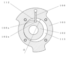
図1および図2において、ロータリ圧縮機100は、駆動軸101と、ピストン102と、シリンダ103と、上軸受としての機能を持つ上端板(以下、上軸受と称す)104と、下軸受としての機能を持つ下端板(以下、下軸受と称す)105と、ベーン106と、吸入穴107aと、を備える。
図1および図2において、ロータリ圧縮機100は、駆動軸101と、ピストン102と、シリンダ103と、上軸受としての機能を持つ上端板(以下、上軸受と称す)104と、下軸受としての機能を持つ下端板(以下、下軸受と称す)105と、ベーン106と、吸入穴107aと、を備える。
密閉容器108の内部全体は吐出管109に連通する吐出圧力雰囲気である。密閉容器108の中央部に電動機110、下部に圧縮機構部111が収納される。圧縮機構部111は、電動機110の回転子110aに固定された駆動軸101で駆動される。
この圧縮機構部111は、シリンダ103、ピストン102及びベーン106を上軸受104と下軸受105で挟み込み、シリンダ103とピストン102との間に形成された空間をベーン106で仕切ることで吸入室112と圧縮室113を形成して圧縮動作を行うように構成されている。
シリンダ103内には、駆動軸101と一体的に構成された偏心軸101aが収納されており、この偏心軸101aにピストン102が回転自在に装着されている。ピストン102の外周には係合溝102aが形成され、先端側に係合部106aが形成されたベーン106がピストン102に揺動自在に連結されている。なお、従来のローリングピストンタイプにあるベーン106の背面側に備えていたバネは無い。
上軸受104には、径方向の吸入穴107aと軸方向の縦穴107bとで構成される吸入通路107が設けられ、吸入室112と連通する。吸入穴107aには吸入ライナー114が圧入される。吸入ライナー114は、密閉容器108内部の高温高圧の吐出ガスと吸入穴107a内部の低温低圧の吸入ガスを仕切っている。
吸入ライナー114には、圧縮機の液圧縮を防止するためにアキュームレータ115が挿入される。アキュームレータ115は、密閉容器108に固定された吸入外管116とともにロー付けまたは溶接されて接続されており、ロータリ圧縮機100に吸入される作動流体を気液分離している。
すなわち、実施の形態1では、上記アキュームレータ115が挿入された吸入ライナー114と吸入外管116とで構成される吸入配管を介して、圧縮機外部からの吸入ガスを吸入室112へと導入するように構成している。尚、吸入配管としてはアキュームレータ115と吸入外管116のみで構成し、吸入穴107aに直接アキュームレータ115を接続するようにしてもよい。
なお、本実施の形態のロータリ圧縮機100は、作動流体として例えば二酸化炭素を用いている。
[1-2.動作]
以上のように構成されたロータリ圧縮機100について、以下その動作を図1および図3に基づいて、説明する。
以上のように構成されたロータリ圧縮機100について、以下その動作を図1および図3に基づいて、説明する。
[1-2-1.圧縮動作]
図3は、クランク角90度毎の吸入室112と圧縮室113の容積変化を説明する図で、容積は、白抜き矢印の方向に変化していく。図示されていない上軸受104の吸入通路107は、ベーン106の左側に位置し、吸入室112と連通している。
図3は、クランク角90度毎の吸入室112と圧縮室113の容積変化を説明する図で、容積は、白抜き矢印の方向に変化していく。図示されていない上軸受104の吸入通路107は、ベーン106の左側に位置し、吸入室112と連通している。
電動機110が付勢され、駆動軸101が回転すると、偏心軸101aがシリンダ103内において偏芯回転し、連結されたピストン102とベーン106とが一体的に運動する。これにより、作動流体の吸入、圧縮が繰り返される。
低温低圧のガスは、アキュームレータ115、吸入ライナー114、吸入通路107を通って吸入室112に吸入される。低温低圧の吸入ガスは、圧縮機構部111にて圧縮される。圧縮された高温高圧のガスは、上軸受104に設けられ、圧縮室113と連通する吐出穴(図示せず)を通り、逆止弁を介してマフラー室117(図1参照)へ吐出する。その後、吐出ガスは、マフラー118に設けられた小孔、圧縮機構部111と電動機110との間の電動機下部空間119、電動機110の各隙間を通る。そして、吐出ガスは、電動機上部空間120に導かれ、吐出管109を通ってロータリ圧縮機100から吐出される。
[1-2-2.給油動作]
密閉容器108の下部には、オイルが貯留されており、圧縮機構部111は、通常、オイルに浸漬した状態にある。駆動軸101の内部には、図示されていない油通路が軸方向に設けられる。油通路の下端部から吸い上げられたオイルは、偏心軸101aに設けられた図示されていない給油穴を通って、偏心軸101aの摺動部を潤滑しながら、ピストン102内周部へ到達する。その後、オイルの一方は、上軸受104および下軸受105のジャーナル軸受摺動部を潤滑して圧縮機構部111外に排出され、オイルのもう一方は、ピストン102の上下端面と上軸受104および下軸受105との摺動部を潤滑しながら、吸入室112と圧縮室113へと供給される。
密閉容器108の下部には、オイルが貯留されており、圧縮機構部111は、通常、オイルに浸漬した状態にある。駆動軸101の内部には、図示されていない油通路が軸方向に設けられる。油通路の下端部から吸い上げられたオイルは、偏心軸101aに設けられた図示されていない給油穴を通って、偏心軸101aの摺動部を潤滑しながら、ピストン102内周部へ到達する。その後、オイルの一方は、上軸受104および下軸受105のジャーナル軸受摺動部を潤滑して圧縮機構部111外に排出され、オイルのもう一方は、ピストン102の上下端面と上軸受104および下軸受105との摺動部を潤滑しながら、吸入室112と圧縮室113へと供給される。
また、ベーン106背面から供給されたオイルは、ベーン106の摺動部を潤滑後、吸入室112と圧縮室113へと供給される。吸入室112と圧縮室113の内部のオイルは、ガスとともに吐出穴121から吐出された後、上述したガスの流れに乗って吐出管109まで到達する。その間に、ほとんどのオイルが吐出ガスと分離されて液滴化し、重力によって密閉容器108の下部へ戻る。
[1-3.効果等]
以上のように、本実施の形態において、ロータリ圧縮機100は、駆動軸101と、ピストン102と、シリンダ103と、上軸受104と、下軸受105と、ベーン106と、吸入穴107aと、を備える。駆動軸101は、偏心軸101aを有する。ピストン102は、偏心軸101aに嵌合される。シリンダ103は、偏心回転するピストン102を収容する。上軸受104および下軸受105は、シリンダ103の上下開口面を閉塞する。ベーン106は、シリンダ103、ピストン102、上軸受104、下軸受105によって形成される空間を、吸入室112と圧縮室113とに区画し、ピストン102と一体的に運動する。そして、吸入穴107aは、シリンダ103ではなく上軸受104に設けられ、吸入ライナー114およびアキュームレータ115が接続される。吸入ライナー114およびアキュームレータ115は、ロータリ圧縮機100外部から吸入ガスを吸入室112へと導入する。
以上のように、本実施の形態において、ロータリ圧縮機100は、駆動軸101と、ピストン102と、シリンダ103と、上軸受104と、下軸受105と、ベーン106と、吸入穴107aと、を備える。駆動軸101は、偏心軸101aを有する。ピストン102は、偏心軸101aに嵌合される。シリンダ103は、偏心回転するピストン102を収容する。上軸受104および下軸受105は、シリンダ103の上下開口面を閉塞する。ベーン106は、シリンダ103、ピストン102、上軸受104、下軸受105によって形成される空間を、吸入室112と圧縮室113とに区画し、ピストン102と一体的に運動する。そして、吸入穴107aは、シリンダ103ではなく上軸受104に設けられ、吸入ライナー114およびアキュームレータ115が接続される。吸入ライナー114およびアキュームレータ115は、ロータリ圧縮機100外部から吸入ガスを吸入室112へと導入する。
これにより、従来のローリングピストンタイプの圧縮機ではベーン106の背面にバネが必要であったものが不要になり、その分シリンダ103の内径Dを大きく、高さHを低くできる。よって、ピストン102外周とシリンダ103内周との接点シール部の漏れ隙間断面積が縮小され、圧縮室113から吸入室112への漏れ損失を低減できる。これと同時に、十分に大きい径の吸入穴107aを設けて吸入通路107の断面積を確保できる。そのため、高さHが低いシリンダ103に径の小さい吸入穴107aを設けた場合に、吸入通路107で圧力損失が生じていたが、その圧力損失の増加がなく、圧縮機効率を向上することができる。
また、本実施の形態のロータリ圧縮機100は、作動流体として二酸化炭素を用いている。
この二酸化炭素冷媒は、HFC系冷媒、HC系冷媒又はHFO系冷媒等の他の冷媒と比較して、吸入室112と圧縮室113との圧力差が大きい。そのため、ピストン102とシリンダ103とのシール部での漏れ損失が圧縮機効率に及ぼす影響が大きい。しかしながら、本開示のような構成であれば、シリンダ103の高さHを極めて低く設定することができるので、ピストン102とシリンダ103とのシール部面積を低減できる。そのため、より効果的に漏れ損失を低減して圧縮機効率を向上することができる。
また、本実施の形態のロータリ圧縮機100は、シリンダ103の内径Dと高さHとの比D/Hを2から13の範囲としている。
これにより、D/Hが小さすぎることで上述の効果が縮小したり、大きすぎることで吸入室112と圧縮室113の表面積が増大して受熱損失が拡大したりすることを避けることができる。そのため、圧縮機効率を最大限に向上させることができる。
なお、上記D/Hは、2から8の範囲にしておくのがより好ましい。
これにより、駆動軸101の軸心と偏心軸101aとの軸心の距離、すなわち偏心量が極端に大きくなってピストン102の挿入性が悪化することを回避することができる。そのため、組立が容易で高効率のロータリ圧縮機100を実現することができる。
また、本実施の形態のロータリ圧縮機100は、ピストン102に係合溝102aを形成するとともにベーン106の先端側に係合部106aを設ける。この係合部106aはピストン102の係合溝102aに嵌合することで、係合部106aを揺動自在に接続している。
これにより、ピストン102に大きな設計変更の必要がないとともに、部品点数が増加することもない。そのため、コストの増加を最小限に抑制することができる。
また、本実施の形態のロータリ圧縮機100は、冷凍サイクル装置に用いて使用する。ピストン102とベーン106は前記したような構成で接続しているため、従来のローリングピストンタイプでの課題であるベーン跳びが発生することがなく、低騒音と高効率を実現することができる。そのため、低圧縮比等の運転条件でも運転が可能である。ロータリ圧縮機100の運転範囲が拡大することで、冷凍サイクル装置の運転の自由度が向上し、システム効率を向上できる。
また、本実施の形態のロータリ圧縮機100は、ヒートポンプ給湯機に用いている。
ヒートポンプ給湯機は他の冷凍サイクル装置と比較して吐出ガスの温度が高い。よって、高温の吐出ガスにさらされる下軸受105の温度も高くなって、吸入通路107を通過する低温の吸入ガスの受熱による体積効率低下の影響が大きい。しかしながら、本開示のロータリ圧縮機は、シリンダ103の内径Dが大きい、言い換えると、密閉容器108内壁からシリンダ103内壁までの距離が短いので、吸入通路107の長さも短い。よって、吸入ガスが受熱されにくくなり、より効果的に体積効率を向上できる。
(実施の形態2)
以下、図4を用いて、実施の形態2を説明する。
以下、図4を用いて、実施の形態2を説明する。
[2-1.構成]
実施の形態2にかかるロータリ圧縮機200は、上シリンダ2031と下シリンダ2032の二つのシリンダが構成され、上シリンダ2031と下シリンダ2032の間に仕切り板221が設けられている。その点が、実施の形態1の一つのシリンダ103で構成されているロータリ圧縮機100と異なる。
実施の形態2にかかるロータリ圧縮機200は、上シリンダ2031と下シリンダ2032の二つのシリンダが構成され、上シリンダ2031と下シリンダ2032の間に仕切り板221が設けられている。その点が、実施の形態1の一つのシリンダ103で構成されているロータリ圧縮機100と異なる。
上シリンダ2031、上ピストン2021及び上ベーン(図示せず)を上軸受204と仕切り板221で挟み込み、下シリンダ2032、下ピストン2022及び下ベーン(図示せず)を仕切り板221と下軸受205で挟み込み、上下シリンダ2031、2032と上下ピストン2021、2022との間に形成された空間を上下ベーンで仕切る。そうすることで、上吸入室2121、下吸入室2122(図番付与せず)、上圧縮室2131(図番付与せず)及び下圧縮室2132を形成して、それぞれの圧縮要素が圧縮動作を行うように構成されている。
上軸受204には、上吸入通路2071が設けられる。上吸入通路2071は、径方向の上吸入穴2071aと軸方向の上縦穴2071bとで構成され、上吸入室2121と連通する。下軸受205には、下吸入通路2072が設けられる。下吸入通路2072は、径方向の下吸入穴2072aと軸方向の下縦穴2072bとで構成され、下吸入室2122と連通する。
ロータリ圧縮機200の閉じ込み容積は、実施の形態1にかかるロータリ圧縮機100と同等であるが、二つのシリンダ2031、2032で分担するので、シリンダ2031、2032の高さHu、Hlは、実施の形態1にかかるロータリ圧縮機100のシリンダ103の高さHよりも低い。
[2-2.動作]
以上のように構成されたロータリ圧縮機200について、その動作を以下説明する。
以上のように構成されたロータリ圧縮機200について、その動作を以下説明する。
[2-2-1.吸入動作]
アキュームレータ215で気液分離された吸入ガスは、二本の配管に分岐して上下吸入通路2071、2072から上下吸入室2121、2122へと吸入される。
アキュームレータ215で気液分離された吸入ガスは、二本の配管に分岐して上下吸入通路2071、2072から上下吸入室2121、2122へと吸入される。
[2-2-2.圧縮動作]
ロータリ圧縮機200のそれぞれの圧縮要素の圧縮動作は、実施の形態1にかかるロータリ圧縮機100と同様である。但し、上下圧縮室2131、2132は、逆位相で圧縮を行う。
ロータリ圧縮機200のそれぞれの圧縮要素の圧縮動作は、実施の形態1にかかるロータリ圧縮機100と同様である。但し、上下圧縮室2131、2132は、逆位相で圧縮を行う。
下シリンダ2032で圧縮された下吐出ガスは、図示されていない連通路を通ってマフラー室217へと流れ、上シリンダ2031で圧縮された上吐出ガスと合流する。その後の吐出ガスの流れは実施の形態1にかかるロータリ圧縮機100と同様である。
[2-3.効果等]
以上のように、本実施の形態において、ロータリ圧縮機200は、駆動軸201と、上ピストン2021と、下ピストン2022と、上シリンダ2031と、下シリンダ2032と、上軸受204と、下軸受205と、上下ベーンと、上吸入穴2071aと、下吸入穴2072aと、仕切り板221を備える。上下圧縮要素は、軸方向に構成される。仕切り板221は、上下圧縮要素の間に備えられる。上軸受204と下軸受205は、駆動軸201を支承する。そして、上吸入穴2071aは上軸受204に、下吸入穴2072aは下軸受205に設けられている。
以上のように、本実施の形態において、ロータリ圧縮機200は、駆動軸201と、上ピストン2021と、下ピストン2022と、上シリンダ2031と、下シリンダ2032と、上軸受204と、下軸受205と、上下ベーンと、上吸入穴2071aと、下吸入穴2072aと、仕切り板221を備える。上下圧縮要素は、軸方向に構成される。仕切り板221は、上下圧縮要素の間に備えられる。上軸受204と下軸受205は、駆動軸201を支承する。そして、上吸入穴2071aは上軸受204に、下吸入穴2072aは下軸受205に設けられている。
これにより、上下ピストン2021、2022による圧縮を逆位相で行うことにより、実施の形態1にかかるロータリ圧縮機100に比較しトルク変動を小さくして振動を低減できる。又、上シリンダ2031と下シリンダ203の内径Dを大きくし、高さHu、Hlを低くできるので、ピストン2021、2022外周とシリンダ2031、2032内周との接点シール部の漏れ隙間断面積がさらに縮小され、圧縮室2131、2132から吸入室2121、2122への漏れ損失を低減できる。しかもこれに加え、上吸入穴2071a、下吸入穴2072aを上軸受204、下軸受205に設けたことで、吸入穴2071a、2072aの径を十分大きくでき、吸入通路2071、2072の断面積を十分確保できる。そのため、高さHu、Hlが低いシリンダ2031、2032に径の小さい吸入穴2071a、2072aを設けた場合に、吸入通路2071、2072で圧力損失が生じていたが、その圧力損失の増加もなく、圧縮機効率を一層向上することができる。
(実施の形態3)
以下、図5を用いて、実施の形態2を説明する。
以下、図5を用いて、実施の形態2を説明する。
[3-1.構成]
実施の形態3にかかるロータリ圧縮機300は、少なくとも、上軸受304と下軸受305ではなく、仕切り板321に吸入穴307aが設けられている点で、実施の形態2にかかるロータリ圧縮機200と異なる。
実施の形態3にかかるロータリ圧縮機300は、少なくとも、上軸受304と下軸受305ではなく、仕切り板321に吸入穴307aが設けられている点で、実施の形態2にかかるロータリ圧縮機200と異なる。
仕切り板321には、径方向の吸入穴307aと、上吸入室3121と連通する上縦穴307bと、下吸入室3122(図番付与せず)と連通する下縦穴307cとで構成される吸入通路307が設けられている。
[3-2.動作]
以上のように構成されたロータリ圧縮機300について、その動作を以下説明する。
以上のように構成されたロータリ圧縮機300について、その動作を以下説明する。
[3-2-1.吸入動作]
アキュームレータ315で気液分離された吸入ガスは、吸入通路307で上下に分配されて上下吸入室3121、3122へと吸入される。
アキュームレータ315で気液分離された吸入ガスは、吸入通路307で上下に分配されて上下吸入室3121、3122へと吸入される。
[3-2-2.圧縮動作]
上下吸入室3121、3122に吸入されたガスは実施の形態2と同様にして圧縮される。
上下吸入室3121、3122に吸入されたガスは実施の形態2と同様にして圧縮される。
[3-3.効果等]
以上のように、本実施の形態において、ロータリ圧縮機300は、駆動軸301と、上ピストン3021と、下ピストン3022と、上シリンダ3031と、下シリンダ3032と、上軸受304と、下軸受305と、上下ベーンと、吸入穴307aと、仕切り板321を備える。上下圧縮要素は、軸方向に構成される。仕切り板321は、上下圧縮要素の間に備えられる。上軸受304と下軸受305は、駆動軸301を支承する。そして、吸入穴307aは仕切り板321に設けられている。
以上のように、本実施の形態において、ロータリ圧縮機300は、駆動軸301と、上ピストン3021と、下ピストン3022と、上シリンダ3031と、下シリンダ3032と、上軸受304と、下軸受305と、上下ベーンと、吸入穴307aと、仕切り板321を備える。上下圧縮要素は、軸方向に構成される。仕切り板321は、上下圧縮要素の間に備えられる。上軸受304と下軸受305は、駆動軸301を支承する。そして、吸入穴307aは仕切り板321に設けられている。
これにより、実施の形態1にかかる一つのシリンダ103が構成されたロータリ圧縮機100のアキュームレータ115をそのまま使用することができる。そのため、実施の形態2にかかるロータリ圧縮機200と比較して、部品点数と組立工数を少なくでき、低コストのアキュームレータ315およびロータリ圧縮機300を実現することができる。その他の効果は実施の形態2と同様である。
(他の実施の形態)
以上のように、本出願において開示する技術の例示として、実施の形態1~3を説明した。しかしながら、本開示における技術は、これに限定されず、変更、置き換え、付加、省略などを行った実施の形態にも適用できる。また、上記実施の形態1~3で説明した各構成要素を組み合わせて、新たな実施の形態とすることも可能である。
以上のように、本出願において開示する技術の例示として、実施の形態1~3を説明した。しかしながら、本開示における技術は、これに限定されず、変更、置き換え、付加、省略などを行った実施の形態にも適用できる。また、上記実施の形態1~3で説明した各構成要素を組み合わせて、新たな実施の形態とすることも可能である。
そこで、以下、他の実施の形態を例示する。
実施の形態1~3では、ロータリ圧縮機の一例として1シリンダのロータリ圧縮機100と2シリンダのロータリ圧縮機200、300を説明した。ロータリ圧縮機は、ガスを圧縮するものであればよい。したがって、ロータリ圧縮機は、1シリンダのロータリ圧縮機100または2シリンダのロータリ圧縮機200、300に限定されない。ただし、1シリンダのロータリ圧縮機100または2シリンダのロータリ圧縮機200、300を用いれば、コストと効率、信頼性のバランスがとれ、量産しやすい利点がある。また、ロータリ圧縮機として、二段圧縮機を用いてもよい。ロータリ圧縮機として二段圧縮機を用いれば、高い圧力比の運転条件でも高低圧差を小さくすることができるので、少ない漏れ損失によって高い効率が実現できる。また、ロータリ圧縮機として、一つのシリンダに複数のベーンと圧縮室を備えてもよい。これを用いれば、1シリンダのロータリ圧縮機100の構成において、2シリンダタイプとほぼ同様の圧縮動作を行うことで、トルク変動を低減でき、または、二段圧縮構成とすることで、高低圧差を小さくすることもできる。よって、少部品点数で低振動または高圧力比運転が可能なロータリ圧縮機が実現できる。
また、実施の形態1では、ベーンの一例として、ピストン102に形成された係合溝102aに揺動自在に嵌合接続される係合部106aを備えるベーン106を説明した。ベーンは、吸入室と圧縮室とを仕切り、常にピストンと一体的に運動するとともに、ベーン背面のバネが不要のものであればよい。したがって、ベーンは、ピストン102に形成された係合溝102aに揺動自在に嵌合接続される係合部106aを備えるベーン106に限定されない。ただし、これを用いれば、前述したようにピストン102に大きな設計変更の必要がないとともに、部品点数が増加することもないので、コストの増加を最小限に抑制することができる。また、ベーンとして、ピストンと完全に一体化され、シリンダに設けた揺動ブッシュを介してピストンが揺動運動するスイング型を用いれば、ベーンとピストンとの接点がない。よって、その微小な隙間での漏れ損失や摺動損失が全くなくなり、ロータリ圧縮機100の高効率化が可能である。
さらにまた、実施の形態1では、作動流体の一例として二酸化炭素を説明した。作動流体は、圧縮性流体であればよい。したがって、作動流体は、二酸化炭素に限定されない。ただし、これを用いれば、前述したようにHFC系冷媒、HC系冷媒又はHFO系冷媒等の他の冷媒と比較して、吸入室112と圧縮室113との圧力差が大きく、ピストン102とシリンダ103とのシール部での漏れ損失が圧縮機効率に及ぼす影響が大きい。しかしながら、本開示の構成を用いてシリンダ103の高さHを極めて低く設定することで、より効果的に漏れ損失を低減できる。また、作動流体として、HFC系冷媒、HC系冷媒はHFO系冷媒等の他の冷媒と二酸化炭素との混合冷媒を用いれば、冷凍サイクルのコンデンサ入口と出口との間の温度グライドを抑制することができる。よって、コンデンサの熱交換効率の低下を抑えることができる。
なお、上述の実施の形態は、本開示における技術を例示するためのものであるから、特許請求の範囲またはその均等の範囲において種々の変更、置き換え、付加、省略などを行うことができる。
本開示は、漏れ損失と圧力損失が生じるロータリ圧縮機および冷凍サイクル装置に適用可能である。具体的には、空気調和機、冷凍機、ブロワ、給湯機などに、本開示は適用可能である。
100 ロータリ圧縮機
101、201、301 駆動軸
101a 偏心軸
102 ピストン
102a 係合溝
103 シリンダ
104、204、304 上軸受(上端板)
105、205、305 下軸受(下端板)
106 ベーン
106a 係合部
107 吸入通路
107a 吸入穴
107b 縦穴
108 密閉容器
109 吐出管
110 電動機
110a 回転子
110b 固定子
111 圧縮機構部
112 吸入室
113 圧縮室
114 吸入ライナー(吸入配管)
115 アキュームレータ(吸入配管)
116 吸入外管(吸入配管)
117 マフラー室
118 マフラー
119 電動機下部空間
120 電動機上部空間
200 ロータリ圧縮機
2021 上ピストン
2022 下ピストン
2031 上シリンダ
2032 下シリンダ
2071 上吸入通路
2071a 上吸入穴
2071b 上縦穴
2072 下吸入通路
2072a 下吸入穴
2072b 下縦穴
2121 上吸入室
2122 下吸入室
2131 上圧縮室
2132 下圧縮室
215 アキュームレータ
217 マフラー室
221 仕切り板
300 ロータリ圧縮機
3021 上ピストン
3022 下ピストン
3031 上シリンダ
3032 下シリンダ
307 吸入通路
307a 吸入穴
307b 上縦穴
307c 下縦穴
3121 上吸入室
3122 下吸入室
315 アキュームレータ
321 仕切り板
Claims (7)
- 偏心軸を有する駆動軸と、
前記偏心軸に嵌合されたピストンと、
偏心回転する前記ピストンを収容するシリンダと、
前記シリンダの上下開口面を閉塞する上端板および下端板と、
前記シリンダ、前記ピストン、前記上下端板によって形成される空間を吸入室と圧縮室とに区画し、前記ピストンと一体的に運動するベーンと、
前記上下端板の少なくともいずれか一方に設けられ、圧縮機外部から吸入ガスを前記吸入室へと導入する吸入配管が接続される吸入穴と、
を備えるロータリ圧縮機。 - 前記シリンダ、前記ピストンおよび前記ベーンによって構成される圧縮要素を軸方向に複数備え、
複数の前記圧縮要素の間に仕切り板を備え、
前記駆動軸を上下で支承する上軸受と下軸受、および前記仕切り板を前記上下端板として構成した、
請求項1に記載のロータリ圧縮機。 - 作動流体として二酸化炭素を用いた、
請求項1または2に記載のロータリ圧縮機。 - 前記シリンダの内径Dと高さHとの比D/Hが2から13の範囲である、
請求項1~3のいずれか1項に記載のロータリ圧縮機。 - 前記ピストンに形成された係合溝と、
前記ベーンの先端側に設けられ、前記係合溝に揺動自在に嵌合接続される係合部を備える、
請求項1~4のいずれか1項に記載のロータリ圧縮機。 - 請求項1~5のいずれか1項に記載のロータリ圧縮機を備える冷凍サイクル装置。
- ヒートポンプ給湯機である、
請求項6に記載の冷凍サイクル装置。
Priority Applications (3)
| Application Number | Priority Date | Filing Date | Title |
|---|---|---|---|
| EP21834557.7A EP4174318A4 (en) | 2020-06-29 | 2021-01-20 | ROTARY COMPRESSOR AND COOLING CIRCUIT DEVICE |
| JP2022533665A JP7678527B2 (ja) | 2020-06-29 | 2021-01-20 | ロータリ圧縮機および冷凍サイクル装置 |
| CN202180017156.9A CN115190944A (zh) | 2020-06-29 | 2021-01-20 | 旋转式压缩机和制冷循环装置 |
Applications Claiming Priority (2)
| Application Number | Priority Date | Filing Date | Title |
|---|---|---|---|
| JP2020111037 | 2020-06-29 | ||
| JP2020-111037 | 2020-06-29 |
Publications (1)
| Publication Number | Publication Date |
|---|---|
| WO2022004028A1 true WO2022004028A1 (ja) | 2022-01-06 |
Family
ID=79315186
Family Applications (1)
| Application Number | Title | Priority Date | Filing Date |
|---|---|---|---|
| PCT/JP2021/001772 Ceased WO2022004028A1 (ja) | 2020-06-29 | 2021-01-20 | ロータリ圧縮機および冷凍サイクル装置 |
Country Status (4)
| Country | Link |
|---|---|
| EP (1) | EP4174318A4 (ja) |
| JP (1) | JP7678527B2 (ja) |
| CN (1) | CN115190944A (ja) |
| WO (1) | WO2022004028A1 (ja) |
Cited By (2)
| Publication number | Priority date | Publication date | Assignee | Title |
|---|---|---|---|---|
| CN118959322A (zh) * | 2024-08-01 | 2024-11-15 | 珠海凌达压缩机有限公司 | 一种基于法兰进气的压缩机 |
| CN119712551A (zh) * | 2024-12-20 | 2025-03-28 | 珠海凌达压缩机有限公司 | 一种压缩机泵体结构、压缩机和空调器 |
Families Citing this family (1)
| Publication number | Priority date | Publication date | Assignee | Title |
|---|---|---|---|---|
| JP2023005307A (ja) * | 2021-06-28 | 2023-01-18 | パナソニックIpマネジメント株式会社 | 圧縮機 |
Citations (5)
| Publication number | Priority date | Publication date | Assignee | Title |
|---|---|---|---|---|
| JPH0381592A (ja) * | 1989-08-24 | 1991-04-05 | Mitsubishi Electric Corp | 2気筒回転式圧縮機 |
| JPH09250477A (ja) * | 1996-03-18 | 1997-09-22 | Toshiba Corp | ロータリコンプレッサ |
| JP2000120572A (ja) | 1998-10-12 | 2000-04-25 | Sanyo Electric Co Ltd | 回転式圧縮機 |
| JP2005139973A (ja) * | 2003-11-05 | 2005-06-02 | Sanyo Electric Co Ltd | 多段圧縮式ロータリ圧縮機 |
| JP2010255624A (ja) * | 2009-03-31 | 2010-11-11 | Panasonic Corp | ロータリ圧縮機 |
Family Cites Families (7)
| Publication number | Priority date | Publication date | Assignee | Title |
|---|---|---|---|---|
| WO2004102005A1 (en) * | 2003-05-19 | 2004-11-25 | Matsushita Electric Industrial Co., Ltd. | Compressor |
| JP2006207532A (ja) * | 2005-01-31 | 2006-08-10 | Sanyo Electric Co Ltd | ロータリコンプレッサ |
| JP5070097B2 (ja) * | 2007-08-28 | 2012-11-07 | 東芝キヤリア株式会社 | 2シリンダ回転式圧縮機およびこれを用いた冷凍サイクル装置 |
| KR101442550B1 (ko) * | 2008-08-06 | 2014-09-22 | 엘지전자 주식회사 | 로터리 압축기 |
| JP5040934B2 (ja) * | 2009-01-22 | 2012-10-03 | パナソニック株式会社 | 密閉型圧縮機 |
| EP2547969A1 (en) * | 2010-03-17 | 2013-01-23 | Panasonic Corporation | Refrigeration cycle apparatus |
| JP5824664B2 (ja) * | 2010-11-17 | 2015-11-25 | パナソニックIpマネジメント株式会社 | ロータリ圧縮機及び冷凍サイクル装置 |
-
2021
- 2021-01-20 CN CN202180017156.9A patent/CN115190944A/zh active Pending
- 2021-01-20 EP EP21834557.7A patent/EP4174318A4/en not_active Withdrawn
- 2021-01-20 WO PCT/JP2021/001772 patent/WO2022004028A1/ja not_active Ceased
- 2021-01-20 JP JP2022533665A patent/JP7678527B2/ja active Active
Patent Citations (5)
| Publication number | Priority date | Publication date | Assignee | Title |
|---|---|---|---|---|
| JPH0381592A (ja) * | 1989-08-24 | 1991-04-05 | Mitsubishi Electric Corp | 2気筒回転式圧縮機 |
| JPH09250477A (ja) * | 1996-03-18 | 1997-09-22 | Toshiba Corp | ロータリコンプレッサ |
| JP2000120572A (ja) | 1998-10-12 | 2000-04-25 | Sanyo Electric Co Ltd | 回転式圧縮機 |
| JP2005139973A (ja) * | 2003-11-05 | 2005-06-02 | Sanyo Electric Co Ltd | 多段圧縮式ロータリ圧縮機 |
| JP2010255624A (ja) * | 2009-03-31 | 2010-11-11 | Panasonic Corp | ロータリ圧縮機 |
Non-Patent Citations (1)
| Title |
|---|
| See also references of EP4174318A4 |
Cited By (2)
| Publication number | Priority date | Publication date | Assignee | Title |
|---|---|---|---|---|
| CN118959322A (zh) * | 2024-08-01 | 2024-11-15 | 珠海凌达压缩机有限公司 | 一种基于法兰进气的压缩机 |
| CN119712551A (zh) * | 2024-12-20 | 2025-03-28 | 珠海凌达压缩机有限公司 | 一种压缩机泵体结构、压缩机和空调器 |
Also Published As
| Publication number | Publication date |
|---|---|
| JP7678527B2 (ja) | 2025-05-16 |
| JPWO2022004028A1 (ja) | 2022-01-06 |
| EP4174318A4 (en) | 2023-12-13 |
| CN115190944A (zh) | 2022-10-14 |
| EP4174318A1 (en) | 2023-05-03 |
Similar Documents
| Publication | Publication Date | Title |
|---|---|---|
| CN103782036B (zh) | 具有两个气缸的旋转式压缩机 | |
| US8419395B2 (en) | Compressor and refrigeration apparatus | |
| EP1975413A1 (en) | Multi stage rotary compressor | |
| CA2440968C (en) | Horizontal two stage rotary compressor | |
| KR101510697B1 (ko) | 회전축 및 이를 적용한 밀폐형 압축기 및 이를 적용한 냉동기기 | |
| JP7678527B2 (ja) | ロータリ圧縮機および冷凍サイクル装置 | |
| US7607904B2 (en) | Rotary compressor with low pressure space surrounding outer peripheral face of compression mechanism and discharge passage passing through housing | |
| WO2013005568A1 (ja) | 多気筒回転式圧縮機及び冷凍サイクル装置 | |
| CN116357546B (zh) | 压缩机及制冷循环装置 | |
| US20100054978A1 (en) | Injectible two-stage compression rotary compressor | |
| CN111836965B (zh) | 旋转压缩机以及制冷循环装置 | |
| WO2022239675A1 (ja) | ロータリ圧縮機および冷凍サイクル装置 | |
| CN213838901U (zh) | 旋转压缩机和制冷循环系统 | |
| KR102788354B1 (ko) | 압축기 | |
| KR101549863B1 (ko) | 밀폐형 압축기 및 이를 적용한 냉동기기 | |
| CA2636093C (en) | Two-stage rotary compressor | |
| WO2021106198A1 (ja) | 圧縮機および冷凍サイクル装置 | |
| KR101462935B1 (ko) | 밀폐형 압축기 및 이를 적용한 냉동기기 | |
| CN112639291A (zh) | 旋转式压缩机以及冷冻循环装置 | |
| WO2022004027A1 (ja) | ロータリ圧縮機および冷凍サイクル装置 | |
| JP2009180108A (ja) | 密閉型圧縮機 | |
| CN112196795A (zh) | 旋转压缩机和制冷循环系统 | |
| CN118749045A (zh) | 旋转式压缩机 | |
| KR101587168B1 (ko) | 로터리 압축기 | |
| CN115949586A (zh) | 旋转式压缩机和换热循环装置 |
Legal Events
| Date | Code | Title | Description |
|---|---|---|---|
| 121 | Ep: the epo has been informed by wipo that ep was designated in this application |
Ref document number: 21834557 Country of ref document: EP Kind code of ref document: A1 |
|
| ENP | Entry into the national phase |
Ref document number: 2022533665 Country of ref document: JP Kind code of ref document: A |
|
| NENP | Non-entry into the national phase |
Ref country code: DE |
|
| ENP | Entry into the national phase |
Ref document number: 2021834557 Country of ref document: EP Effective date: 20230130 |