WO2022004099A1 - リリーフ弁、及びそれを用いた冷却回路 - Google Patents
リリーフ弁、及びそれを用いた冷却回路 Download PDFInfo
- Publication number
- WO2022004099A1 WO2022004099A1 PCT/JP2021/016002 JP2021016002W WO2022004099A1 WO 2022004099 A1 WO2022004099 A1 WO 2022004099A1 JP 2021016002 W JP2021016002 W JP 2021016002W WO 2022004099 A1 WO2022004099 A1 WO 2022004099A1
- Authority
- WO
- WIPO (PCT)
- Prior art keywords
- relief valve
- side connection
- connection pipe
- supply
- pipe
- Prior art date
- Legal status (The legal status is an assumption and is not a legal conclusion. Google has not performed a legal analysis and makes no representation as to the accuracy of the status listed.)
- Ceased
Links
Images

Classifications
-
- F—MECHANICAL ENGINEERING; LIGHTING; HEATING; WEAPONS; BLASTING
- F16—ENGINEERING ELEMENTS AND UNITS; GENERAL MEASURES FOR PRODUCING AND MAINTAINING EFFECTIVE FUNCTIONING OF MACHINES OR INSTALLATIONS; THERMAL INSULATION IN GENERAL
- F16K—VALVES; TAPS; COCKS; ACTUATING-FLOATS; DEVICES FOR VENTING OR AERATING
- F16K17/00—Safety valves; Equalising valves, e.g. pressure relief valves
- F16K17/02—Safety valves; Equalising valves, e.g. pressure relief valves opening on surplus pressure on one side; closing on insufficient pressure on one side
- F16K17/04—Safety valves; Equalising valves, e.g. pressure relief valves opening on surplus pressure on one side; closing on insufficient pressure on one side spring-loaded
-
- F—MECHANICAL ENGINEERING; LIGHTING; HEATING; WEAPONS; BLASTING
- F01—MACHINES OR ENGINES IN GENERAL; ENGINE PLANTS IN GENERAL; STEAM ENGINES
- F01P—COOLING OF MACHINES OR ENGINES IN GENERAL; COOLING OF INTERNAL-COMBUSTION ENGINES
- F01P11/00—Component parts, details, or accessories not provided for in, or of interest apart from, groups F01P1/00 - F01P9/00
- F01P11/14—Indicating devices; Other safety devices
- F01P11/18—Indicating devices; Other safety devices concerning coolant pressure, coolant flow, or liquid-coolant level
-
- F—MECHANICAL ENGINEERING; LIGHTING; HEATING; WEAPONS; BLASTING
- F16—ENGINEERING ELEMENTS AND UNITS; GENERAL MEASURES FOR PRODUCING AND MAINTAINING EFFECTIVE FUNCTIONING OF MACHINES OR INSTALLATIONS; THERMAL INSULATION IN GENERAL
- F16K—VALVES; TAPS; COCKS; ACTUATING-FLOATS; DEVICES FOR VENTING OR AERATING
- F16K27/00—Construction of housing; Use of materials therefor
- F16K27/02—Construction of housing; Use of materials therefor of lift valves
- F16K27/0209—Check valves or pivoted valves
-
- F—MECHANICAL ENGINEERING; LIGHTING; HEATING; WEAPONS; BLASTING
- F16—ENGINEERING ELEMENTS AND UNITS; GENERAL MEASURES FOR PRODUCING AND MAINTAINING EFFECTIVE FUNCTIONING OF MACHINES OR INSTALLATIONS; THERMAL INSULATION IN GENERAL
- F16K—VALVES; TAPS; COCKS; ACTUATING-FLOATS; DEVICES FOR VENTING OR AERATING
- F16K47/00—Means in valves for absorbing fluid energy
-
- F—MECHANICAL ENGINEERING; LIGHTING; HEATING; WEAPONS; BLASTING
- F28—HEAT EXCHANGE IN GENERAL
- F28F—DETAILS OF HEAT-EXCHANGE AND HEAT-TRANSFER APPARATUS, OF GENERAL APPLICATION
- F28F27/00—Control arrangements or safety devices specially adapted for heat-exchange or heat-transfer apparatus
- F28F27/02—Control arrangements or safety devices specially adapted for heat-exchange or heat-transfer apparatus for controlling the distribution of heat-exchange media between different channels
-
- F—MECHANICAL ENGINEERING; LIGHTING; HEATING; WEAPONS; BLASTING
- F01—MACHINES OR ENGINES IN GENERAL; ENGINE PLANTS IN GENERAL; STEAM ENGINES
- F01P—COOLING OF MACHINES OR ENGINES IN GENERAL; COOLING OF INTERNAL-COMBUSTION ENGINES
- F01P7/00—Controlling of coolant flow
- F01P7/14—Controlling of coolant flow the coolant being liquid
- F01P2007/146—Controlling of coolant flow the coolant being liquid using valves
-
- F—MECHANICAL ENGINEERING; LIGHTING; HEATING; WEAPONS; BLASTING
- F28—HEAT EXCHANGE IN GENERAL
- F28F—DETAILS OF HEAT-EXCHANGE AND HEAT-TRANSFER APPARATUS, OF GENERAL APPLICATION
- F28F2250/00—Arrangements for modifying the flow of the heat exchange media, e.g. flow guiding means; Particular flow patterns
- F28F2250/06—Derivation channels, e.g. bypass
-
- F—MECHANICAL ENGINEERING; LIGHTING; HEATING; WEAPONS; BLASTING
- F28—HEAT EXCHANGE IN GENERAL
- F28F—DETAILS OF HEAT-EXCHANGE AND HEAT-TRANSFER APPARATUS, OF GENERAL APPLICATION
- F28F2265/00—Safety or protection arrangements; Arrangements for preventing malfunction
- F28F2265/12—Safety or protection arrangements; Arrangements for preventing malfunction for preventing overpressure
Definitions
- the present invention relates to a relief valve and a cooling circuit using the relief valve.
- a cooling circuit that cools a cooling target with a cooling medium is known (for example, see Japanese Patent Publication No. 55-123622).
- a relief valve is provided to release the pressure in order to protect the heat exchange section when the pressure of the cooling medium supplied to the heat exchange section is high.
- the supply side connection pipe connected to the supply pipe that supplies the cooling medium to the heat exchange unit and the discharge side connection pipe connected to the discharge pipe that discharges the cooling medium are arranged along the supply side connection pipe.
- a relief valve is provided at the part that bypasses the discharge side connection pipe and the pressure is released to the discharge pipe through the relief valve when the pressure of the cooling medium in the supply pipe is high, the cooling medium is the supply side connection pipe. It may flow in a U-turn from the middle of the pipe to the discharge side connecting pipe. In such a case, it may be difficult to secure the flow rate through the relief valve.
- the inlet of the cooling medium in the relief valve is the inflow port and the outlet of the cooling medium is the outflow port
- this is the valve of the inflow port and the relief valve when the relief valve is provided so that the cooling medium makes a U-turn as described above.
- the main body is concentrically arranged, the cooling medium flows unevenly toward the outside of the U-turn portion, that is, the side closer to the heat exchange portion, and the flow velocity of the cooling medium is near the outlet in the discharge side connection pipe. This is because there is a portion where the cooling speed increases, and the flow path resistance increases in this portion.
- the flow rate can be increased by increasing the size of the relief valve, sufficient mounting space cannot be secured due to the positional relationship with other devices, and there is a limit to increasing the size of the relief valve.
- the relief valve of the present invention is used.
- the supply side connection pipe connected to the supply pipe,
- the discharge side connection pipe arranged along the supply side connection pipe and connected to the discharge pipe,
- a housing having an inflow port connected to the supply side connection pipe and the discharge side connection pipe and opened in the supply side connection pipe, and an outlet having an outlet open in the discharge side connection pipe.
- the valve seat provided in the housing and A valve body that is arranged in the housing and is seated on the valve seat to block communication between the inlet and the outlet, and is separated from the valve seat to communicate the inlet and the outlet.
- An urging member that urges the valve body to sit on the valve seat, and Equipped with The inflow port is provided in the housing so as to be eccentric in the extending direction of the supply-side connecting pipe with respect to the central axis of the valve body.
- the supply side connection pipe that supplies the cooling medium to the heat exchange section and the discharge side connection pipe that discharges the cooling medium are arranged along each other without increasing the size, and the supply side connection pipe is arranged.
- a relief valve is provided in the bypass portion with the discharge side connection pipe, and when the pressure of the cooling medium supplied to the heat exchange section is high, the pressure is applied from the middle of the supply side connection pipe to the discharge side via the relief valve. Even when the cooling medium is released to the connecting pipe and flows so as to make a U-turn, the flow rate can be secured without increasing the size of the relief valve.
- the cooling medium can easily pass through the heat exchange portion side in the relief valve, that is, the side on which the cooling medium actively flows. Is.
- the outlet is provided in the housing so as to be eccentric in the extending direction of the discharge side connecting pipe.
- the cooling circuit of the present invention is Equipped with the relief valve
- the supply-side connecting pipe guides the cooling medium to the heat exchange section.
- the discharge side connection pipe is characterized in that it discharges a cooling medium.
- the pressure of the cooling medium supplied to the heat exchange section when the pressure of the cooling medium supplied to the heat exchange section is high, the pressure is released from the middle of the supply side connection pipe to the discharge side connection pipe via the relief valve, and the cooling medium makes a U-turn. Even when the flow is such that the flow can be secured, the flow path can be secured without increasing the size of the relief valve.
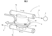
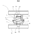
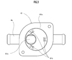
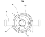
- FIG. 1 is a perspective view showing a relief valve according to the first embodiment of the present invention. It is explanatory drawing which shows the relief valve of 1st Embodiment in the cross section. It is explanatory drawing which shows the 1st half body of the relief valve of 1st Embodiment from the 2nd half body side. It is explanatory drawing which shows the 2nd half body of the relief valve of 1st Embodiment from the 1st half body side. It is explanatory drawing which shows the 1st half body of the relief valve of the 2nd Embodiment of this invention from the 2nd half body side. It is explanatory drawing which shows the 2nd half body of the relief valve of 3rd Embodiment of this invention from the 1st half body side.
- the cooling circuit including the relief valve 1 of the first embodiment uses a cooling medium such as cooling water that has cooled and warmed the internal combustion engine, a radiator, a heater core, and an AT (automatic transmission) / CVT. (Stepless transmission), EGR (exhaust gas recirculation) and other heat exchange units circulate to exchange heat, and the supply pipe 4 and the supply pipe 4 that supply the cooling medium to the heat exchange unit 3 It is provided with a relief valve 1 that releases the pressure of the supply pipe 4 to the discharge pipe 5 when the pressure becomes equal to or higher than a predetermined value.
- a cooling medium such as cooling water that has cooled and warmed the internal combustion engine, a radiator, a heater core, and an AT (automatic transmission) / CVT.
- EGR exhaust gas recirculation
- other heat exchange units circulate to exchange heat
- the supply pipe 4 and the supply pipe 4 that supply the cooling medium to the heat exchange unit 3 It is provided with a relief valve 1 that releases the pressure of the supply pipe 4 to the discharge pipe 5 when
- the relief valve 1 is a housing that connects the supply side connection pipe 4a connected to the supply pipe 4, the discharge side connection pipe 5a connected to the discharge pipe 5, and the supply side connection pipe 4a and the discharge side connection pipe 5a. 6 and.
- the discharge side connecting pipe 5a is arranged in parallel or substantially parallel along the supply side connecting pipe 4a.
- the housing 6 is configured by superimposing a cylindrical first half body 61 connected to the supply side connection pipe 4a and a hemispherical second half body 62 connected to the discharge side connection pipe 5a. ..
- the relief valve 1 has a bottomed tubular valve body 7 housed in the first half body 61 and a valve body 7 housed in the second half body 62. It includes an urging member 8 made of a coil spring that urges the semifield 61 side.
- the valve body 7 is arranged so that its opening side faces the second semifield 62 side, and is movably arranged in the housing 6 along the central axis direction of the valve body 7.
- An overhanging portion 7a projecting outward in the radial direction is provided on the opening edge of the valve body 7 on the second half body 62 side.
- the opening edge 61a of the first half body 61 functions as a valve seat on which the valve body 7 takes off and sits.
- FIG. 3 is a diagram showing the first half body 61 from the second half body 62 side.
- three ribs 61b extending along the direction in which the valve body 7 is pressed by the urging member 8 are arranged at equal intervals in the circumferential direction.
- the rib 61b maintains the center position of the valve body 7 in the housing 6 while allowing the valve body 7 to move in the urging direction by the urging member 8.
- the first half body 61 is provided with an inflow port 61c communicating with the supply pipe 4.
- the inflow port 61c is provided so as to be eccentric with respect to the central axis of the valve body 7 in the extending direction of the supply pipe 4 and in the direction away from the heat exchange portion 3.
- FIG. 4 is a diagram showing the second half body 62 from the first half body 61 side. With reference to FIGS. 2 and 4, the opening edge of the second half 62 superimposed on the first half 61 is liquid-tightly sealed between the first half 61 and the second half 62. An annular groove is provided in which the O-ring 62a is fitted.
- valve body 7 moves to the second semifield 62 side against the urging force of the urging member 8 due to the pressure of the cooling medium. do.
- the amount of movement of the valve body 7 to the second half body 62 side is restricted so as to appropriately secure a gap between the valve body 7 and the second half body 62.
- the three ribs 62b are provided at equal intervals in the circumferential direction of the second half body 62.
- the second half body 62 is provided with an outlet 62c that communicates with the discharge pipe 5.
- the outlet 62c is provided so as to be concentric with the central axis of the valve body 7.
- the flow rate of the cooling medium can be secured without increasing the size of the relief valve 1.
- the inflow port 61c is eccentric with respect to the central axis of the valve body 7 in the extending direction of the supply-side connecting pipe 4a and in the direction away from the heat exchange portion 3. This is because it is possible to prevent the cooling medium from flowing relatively evenly and increasing the flow path resistance on the outlet 62c side. Further, since the cooling medium flows relatively evenly with respect to the valve body 7, it is possible to suppress the valve body 7 from tilting.
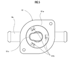
- FIG. 5 is a diagram showing the first half body 61 of the relief valve 1 of the second embodiment of the present invention from the second half body 62 side.
- the relief valve 1 of the second embodiment is all the first embodiment except that the shape of the inflow port 61c provided in the first semifield 61 is a snowman shape with the head facing away from the heat exchange unit 3. It is configured in the same way as the form.
- the inflow port 61c of the second embodiment the fact that the inflow port 61c of the present invention is eccentric with respect to the central axis of the valve body 7 in the extending direction of the supply pipe 4 means that the inflow port 61c is opened. It means that the center point of the area is deviated from the central axis of the valve body 7 in the extending direction of the supply pipe 4.
- the relief valve 1 of the second embodiment can secure the flow rate of the cooling medium of the relief valve 1 without increasing the size of the relief valve 1.
- FIG. 6 is a diagram showing the second half body 62 of the relief valve 1 of the third embodiment of the present invention from the first half body 61 side.
- the relief valve 1 of the third embodiment is specifically provided in that the outlet 62c provided in the second half body 62 is provided eccentrically with respect to the central axis of the valve body 7 in the extending direction of the discharge pipe 5.
- the outlet 62c is configured to be the same as that of the first embodiment except that the outlet 62c is provided eccentrically in a direction away from the heat exchange portion 3 like the inlet 61c. According to the relief valve 1 of the third embodiment, the flow rate of the cooling medium of the relief valve 1 can be more appropriately secured.
- the perfectly circular inlet 61c and outlet 62c have been described, but the shapes of the inlet 61c and the outlet 62c are not limited to this, and may be, for example, an elliptical shape.
- the eccentric direction of the inflow port 61c may be the extending direction of the supply-side connecting pipe 4a, and may be eccentric in a direction approaching the heat exchange unit 3, for example.
- the outlet 62c is the heat exchange section even in the direction away from the heat exchange section 3 as long as it is in the extending direction of the discharge side connection pipe 5a.
- the flow rate of the cooling medium can be more appropriately secured regardless of the direction approaching 3 or the eccentricity in either direction.
Landscapes
- Engineering & Computer Science (AREA)
- General Engineering & Computer Science (AREA)
- Mechanical Engineering (AREA)
- Physics & Mathematics (AREA)
- Thermal Sciences (AREA)
- Chemical & Material Sciences (AREA)
- Combustion & Propulsion (AREA)
- Safety Valves (AREA)
Abstract
Description
本発明は、以上の点に鑑み、大型化することなく、流量を確保できるリリーフ弁、及びそれを用いた冷却回路を提供することを目的とする。
供給管に接続される供給側接続管と、
前記供給側接続管に沿うように配置されて排出管に接続される排出側接続管と、
前記供給側接続管と前記排出側接続管とに接続され、且つ前記供給側接続管内に開口する流入口、及び前記排出側接続管内に開口する流出口を有する筐体と、
前記筐体内に設けられた弁座と、
前記筐体内に配置され、前記弁座に着座させることにより前記流入口と前記流出口との連通を遮断し、前記弁座から離れることにより前記流入口と前記流出口とを連通させる弁本体と、
前記弁本体を前記弁座に着座させる方向へ付勢する付勢部材と、
を備え、
前記流入口は、前記弁本体の中心軸線に対して、前記供給側接続管の延在方向に偏心するように前記筐体に設けられていることを特徴とする。
前記リリーフ弁を備え、
前記供給側接続管は、熱交換部に冷却媒体を導くものであり、
前記排出側接続管は、冷却媒体を排出するものであることを特徴とする。
図1から図4を参照して、本発明のリリーフ弁の第1実施形態を説明する。
図5は、本発明の第2実施形態のリリーフ弁1の第1半体61を第2半体62側から示した図である。第2実施形態のリリーフ弁1は、第1半体61に設けられた流入口61cの形状が熱交換部3から離隔する方向に頭を向けた雪だるま形状であること以外は、全て第1実施形態と同一に構成されている。
図6は、本発明の第3実施形態のリリーフ弁1の第2半体62を第1半体61側から示した図である。第3実施形態のリリーフ弁1は、第2半体62に設けられた流出口62cが弁本体7の中心軸線に対して排出管5の延在方向に偏心して設けられている点、具体的には流出口62cが流入口61cと同様に熱交換部3から離隔する方向に偏心して設けられている点、を除いて、全て第1実施形態と同一に構成されている。第3実施形態のリリーフ弁1によれば、リリーフ弁1の冷却媒体の流量をより適切に確保することができる。
第1実施形態においては、真円形状の流入口61c及び流出口62cを説明したが、流入口61cと流出口62cの形状はこれに限らず、例えば、楕円形状としてもよい。
3 熱交換部
4 供給管
4a 供給側接続管
5 排出管
5a 排出側接続管
6 筐体
61 第1半体
61a 開口縁(弁座)
61b リブ
61c 流入口
62 第2半体
62a Oリング
62b リブ
62c 流出口
7 弁本体
7a 張出部
8 付勢部材
Claims (4)
- 供給管に接続される供給側接続管と、
前記供給側接続管に沿うように配置されて排出管に接続される排出側接続管と、
前記供給側接続管と前記排出側接続管とに接続され、且つ前記供給側接続管内に開口する流入口、及び前記排出側接続管内に開口する流出口を有する筐体と、
前記筐体内に設けられた弁座と、
前記筐体内に配置され、前記弁座に着座させることにより前記流入口と前記流出口との連通を遮断し、前記弁座から離れることにより前記流入口と前記流出口とを連通させる弁本体と、
前記弁本体を前記弁座に着座させる方向へ付勢する付勢部材と、
を備え、
前記流入口は、前記弁本体の中心軸線に対して、前記供給側接続管の延在方向に偏心するように前記筐体に設けられていることを特徴とするリリーフ弁。 - 請求項1に記載のリリーフ弁であって、
前記流出口は、前記排出側接続管の延在方向に偏心するように前記筐体に設けられていることを特徴とするリリーフ弁。 - 請求項1に記載のリリーフ弁を備え、
前記供給側接続管は、熱交換部に冷却媒体を導くものであり、
前記排出側接続管は、冷却媒体を排出するものであることを特徴とする冷却回路。 - 請求項2に記載のリリーフ弁を備え、
前記供給側接続管は、熱交換部に冷却媒体を導くものであり、
前記排出側接続管は、冷却媒体を排出するものであることを特徴とする冷却回路。
Priority Applications (3)
| Application Number | Priority Date | Filing Date | Title |
|---|---|---|---|
| EP21834048.7A EP4137723A4 (en) | 2020-07-02 | 2021-04-20 | Relief valve and cooling circuit using same |
| US17/925,200 US12025233B2 (en) | 2020-07-02 | 2021-04-20 | Relief valve and cooling circuit using same |
| CN202180039673.6A CN115702303A (zh) | 2020-07-02 | 2021-04-20 | 溢流阀以及使用该溢流阀的冷却回路 |
Applications Claiming Priority (2)
| Application Number | Priority Date | Filing Date | Title |
|---|---|---|---|
| JP2020-115169 | 2020-07-02 | ||
| JP2020115169A JP7599288B2 (ja) | 2020-07-02 | 2020-07-02 | リリーフ弁、及びそれを用いた冷却回路 |
Publications (1)
| Publication Number | Publication Date |
|---|---|
| WO2022004099A1 true WO2022004099A1 (ja) | 2022-01-06 |
Family
ID=79315698
Family Applications (1)
| Application Number | Title | Priority Date | Filing Date |
|---|---|---|---|
| PCT/JP2021/016002 Ceased WO2022004099A1 (ja) | 2020-07-02 | 2021-04-20 | リリーフ弁、及びそれを用いた冷却回路 |
Country Status (6)
| Country | Link |
|---|---|
| US (1) | US12025233B2 (ja) |
| EP (1) | EP4137723A4 (ja) |
| JP (1) | JP7599288B2 (ja) |
| CN (1) | CN115702303A (ja) |
| TW (1) | TW202219408A (ja) |
| WO (1) | WO2022004099A1 (ja) |
Citations (7)
| Publication number | Priority date | Publication date | Assignee | Title |
|---|---|---|---|---|
| JPS55123622U (ja) | 1979-02-26 | 1980-09-02 | ||
| JPH0725500Y2 (ja) * | 1990-07-20 | 1995-06-07 | 東芝精機株式会社 | 圧力調整弁 |
| JPH0989313A (ja) * | 1995-09-29 | 1997-04-04 | Rinnai Corp | 吸収式冷凍装置を用いた空調機 |
| WO2007040169A1 (ja) * | 2005-10-03 | 2007-04-12 | Mitsuba Corporation | 圧力制御装置 |
| JP2007291927A (ja) * | 2006-04-24 | 2007-11-08 | Mazda Motor Corp | エンジンの冷却装置 |
| JP2014145468A (ja) * | 2013-01-30 | 2014-08-14 | Nippon Thermostat Co Ltd | サーモバルブ |
| JP2019039333A (ja) * | 2017-08-24 | 2019-03-14 | 株式会社デンソー | 圧力調節装置 |
Family Cites Families (9)
| Publication number | Priority date | Publication date | Assignee | Title |
|---|---|---|---|---|
| US1871535A (en) | 1932-08-16 | Valve | ||
| FR2504974A1 (fr) * | 1981-04-30 | 1982-11-05 | Bennes Marrel | Valve hydraulique de coulissement pour verin de mine |
| CA2488345A1 (en) | 2004-11-24 | 2006-05-24 | Dana Canada Corporation | By-pass valve for heat exchanger |
| US8020782B2 (en) | 2005-09-20 | 2011-09-20 | Edc Automotive, Llc | Transmission thermostat device |
| JP2007240041A (ja) | 2006-03-07 | 2007-09-20 | Tgk Co Ltd | 膨張弁 |
| US8991719B2 (en) | 2009-07-09 | 2015-03-31 | Dana Canada Corporation | Low pressure drop thermal by-pass valve |
| DE102013007186A1 (de) | 2013-04-25 | 2014-10-30 | Man Truck & Bus Ag | Leitungssystem für ein Kraftfahrzeug |
| CN109780259B (zh) * | 2017-11-13 | 2021-02-02 | 浙江三花汽车零部件有限公司 | 调温阀 |
| US20200347946A1 (en) * | 2019-04-30 | 2020-11-05 | Gorman-Rupp Pumps | Air release valve |
-
2020
- 2020-07-02 JP JP2020115169A patent/JP7599288B2/ja active Active
-
2021
- 2021-04-20 EP EP21834048.7A patent/EP4137723A4/en not_active Withdrawn
- 2021-04-20 CN CN202180039673.6A patent/CN115702303A/zh active Pending
- 2021-04-20 WO PCT/JP2021/016002 patent/WO2022004099A1/ja not_active Ceased
- 2021-04-20 US US17/925,200 patent/US12025233B2/en active Active
- 2021-06-28 TW TW110123597A patent/TW202219408A/zh unknown
Patent Citations (7)
| Publication number | Priority date | Publication date | Assignee | Title |
|---|---|---|---|---|
| JPS55123622U (ja) | 1979-02-26 | 1980-09-02 | ||
| JPH0725500Y2 (ja) * | 1990-07-20 | 1995-06-07 | 東芝精機株式会社 | 圧力調整弁 |
| JPH0989313A (ja) * | 1995-09-29 | 1997-04-04 | Rinnai Corp | 吸収式冷凍装置を用いた空調機 |
| WO2007040169A1 (ja) * | 2005-10-03 | 2007-04-12 | Mitsuba Corporation | 圧力制御装置 |
| JP2007291927A (ja) * | 2006-04-24 | 2007-11-08 | Mazda Motor Corp | エンジンの冷却装置 |
| JP2014145468A (ja) * | 2013-01-30 | 2014-08-14 | Nippon Thermostat Co Ltd | サーモバルブ |
| JP2019039333A (ja) * | 2017-08-24 | 2019-03-14 | 株式会社デンソー | 圧力調節装置 |
Non-Patent Citations (1)
| Title |
|---|
| See also references of EP4137723A4 |
Also Published As
| Publication number | Publication date |
|---|---|
| JP7599288B2 (ja) | 2024-12-13 |
| TW202219408A (zh) | 2022-05-16 |
| US12025233B2 (en) | 2024-07-02 |
| US20230194009A1 (en) | 2023-06-22 |
| EP4137723A4 (en) | 2024-04-24 |
| CN115702303A (zh) | 2023-02-14 |
| JP2022012966A (ja) | 2022-01-18 |
| EP4137723A1 (en) | 2023-02-22 |
Similar Documents
| Publication | Publication Date | Title |
|---|---|---|
| CN111120695B (zh) | 流量控制阀 | |
| US11098808B2 (en) | Control valve | |
| US20120247582A1 (en) | Temperature Control Valve With Pressure Relief | |
| US11079027B2 (en) | Control valve | |
| CN110366654B (zh) | 控制阀 | |
| WO2018169081A1 (ja) | 制御バルブ | |
| JP7785099B2 (ja) | 制御バルブ | |
| JP5895942B2 (ja) | エンジンの冷却制御装置 | |
| JP6995832B2 (ja) | 制御バルブ | |
| JP2023520926A (ja) | ポペット弁を備えるオイルスプレーチューブ | |
| JP2021152405A (ja) | 制御バルブ | |
| JP2022012966A (ja) | リリーフ弁、及びそれを用いた冷却回路 | |
| WO2021161666A1 (ja) | 冷却水温度制御装置 | |
| JP2021076196A (ja) | リニアアクチュエータ、弁装置及び弁装置の製造方法 | |
| JP7756557B2 (ja) | 制御バルブ | |
| JP2020153377A (ja) | 流量調整バルブ | |
| US20210291621A1 (en) | Control valve | |
| JP2018204744A (ja) | 流量制御弁 | |
| JP7409928B2 (ja) | 制御バルブ | |
| JP7417446B2 (ja) | 制御バルブ | |
| KR102690515B1 (ko) | 멀티웨이밸브 장치 | |
| JP2021148244A (ja) | 制御バルブ | |
| JP2024130126A (ja) | 制御バルブ | |
| JP2021124189A (ja) | バルブ装置 | |
| JPH03209075A (ja) | 流体制御装置 |
Legal Events
| Date | Code | Title | Description |
|---|---|---|---|
| 121 | Ep: the epo has been informed by wipo that ep was designated in this application |
Ref document number: 21834048 Country of ref document: EP Kind code of ref document: A1 |
|
| ENP | Entry into the national phase |
Ref document number: 2021834048 Country of ref document: EP Effective date: 20221116 |
|
| WWE | Wipo information: entry into national phase |
Ref document number: 202317001349 Country of ref document: IN |
|
| NENP | Non-entry into the national phase |
Ref country code: DE |
|
| WWW | Wipo information: withdrawn in national office |
Ref document number: 2021834048 Country of ref document: EP |