WO2022004479A1 - Pneu - Google Patents
Pneu Download PDFInfo
- Publication number
- WO2022004479A1 WO2022004479A1 PCT/JP2021/023535 JP2021023535W WO2022004479A1 WO 2022004479 A1 WO2022004479 A1 WO 2022004479A1 JP 2021023535 W JP2021023535 W JP 2021023535W WO 2022004479 A1 WO2022004479 A1 WO 2022004479A1
- Authority
- WO
- WIPO (PCT)
- Prior art keywords
- transponder
- tire
- layer
- carcass layer
- pneumatic tire
- Prior art date
- Legal status (The legal status is an assumption and is not a legal conclusion. Google has not performed a legal analysis and makes no representation as to the accuracy of the status listed.)
- Ceased
Links
Images




Classifications
-
- B—PERFORMING OPERATIONS; TRANSPORTING
- B60—VEHICLES IN GENERAL
- B60C—VEHICLE TYRES; TYRE INFLATION; TYRE CHANGING; CONNECTING VALVES TO INFLATABLE ELASTIC BODIES IN GENERAL; DEVICES OR ARRANGEMENTS RELATED TO TYRES
- B60C19/00—Tyre parts or constructions not otherwise provided for
-
- B—PERFORMING OPERATIONS; TRANSPORTING
- B60—VEHICLES IN GENERAL
- B60C—VEHICLE TYRES; TYRE INFLATION; TYRE CHANGING; CONNECTING VALVES TO INFLATABLE ELASTIC BODIES IN GENERAL; DEVICES OR ARRANGEMENTS RELATED TO TYRES
- B60C15/00—Tyre beads, e.g. ply turn-up or overlap
- B60C15/0009—Tyre beads, e.g. ply turn-up or overlap features of the carcass terminal portion
- B60C15/0036—Tyre beads, e.g. ply turn-up or overlap features of the carcass terminal portion with high ply turn-up, i.e. folded around the bead core and terminating radially above the point of maximum section width
-
- B—PERFORMING OPERATIONS; TRANSPORTING
- B60—VEHICLES IN GENERAL
- B60C—VEHICLE TYRES; TYRE INFLATION; TYRE CHANGING; CONNECTING VALVES TO INFLATABLE ELASTIC BODIES IN GENERAL; DEVICES OR ARRANGEMENTS RELATED TO TYRES
- B60C15/00—Tyre beads, e.g. ply turn-up or overlap
- B60C15/06—Flipper strips, fillers, or chafing strips and reinforcing layers for the construction of the bead
-
- B—PERFORMING OPERATIONS; TRANSPORTING
- B60—VEHICLES IN GENERAL
- B60C—VEHICLE TYRES; TYRE INFLATION; TYRE CHANGING; CONNECTING VALVES TO INFLATABLE ELASTIC BODIES IN GENERAL; DEVICES OR ARRANGEMENTS RELATED TO TYRES
- B60C9/00—Reinforcements or ply arrangement of pneumatic tyres
- B60C9/0042—Reinforcements made of synthetic materials
-
- B—PERFORMING OPERATIONS; TRANSPORTING
- B60—VEHICLES IN GENERAL
- B60C—VEHICLE TYRES; TYRE INFLATION; TYRE CHANGING; CONNECTING VALVES TO INFLATABLE ELASTIC BODIES IN GENERAL; DEVICES OR ARRANGEMENTS RELATED TO TYRES
- B60C9/00—Reinforcements or ply arrangement of pneumatic tyres
- B60C2009/0071—Reinforcements or ply arrangement of pneumatic tyres characterised by special physical properties of the reinforcements
- B60C2009/0085—Tensile strength
Definitions
- the present invention relates to a pneumatic tire in which a transponder is embedded, and more particularly to a pneumatic tire that makes it possible to improve the steering stability of the tire while ensuring the communication property of the transponder.
- an RFID tag transponder
- an organic fiber cord is used for the reinforcing cord (carcass cord) constituting the carcass layer
- rayon, polyester or the like can be exemplified as the organic fiber.
- the rayon has high rigidity and can obtain excellent steering stability, while the rayon is hygroscopic.
- the communication property of the transponder deteriorates because of the high value.
- An object of the present invention is to provide a pneumatic tire capable of improving the steering stability of the tire while ensuring the communication property of the transponder.
- the pneumatic tire of the present invention has a tread portion extending in the tire circumferential direction to form an annular shape, a pair of sidewall portions arranged on both sides of the tread portion, and these sidewall portions.
- a pair of bead portions arranged inside in the tire radial direction are provided, a bead filler is arranged on the outer periphery of the bead core of each bead portion, a carcass layer is mounted between the pair of bead portions, and the tread portion is described.
- the carcass layer is composed of a reinforcing cord made of a polyester fiber cord, the cutting elongation EB of the reinforcing cord of the carcass layer is in the range of 20% to 30%, and the tire is tired from the upper end of the bead core. It is characterized in that a transponder is arranged between a position of 15 mm on the outer side in the radial direction and a position of 5 mm on the inner side in the radial direction of the tire from the end of the belt layer.
- the carcass layer is composed of a reinforcing cord made of a polyester fiber cord, and the cutting elongation EB of the reinforcing cord of the carcass layer is in the range of 20% to 30%.
- the carcass layer is composed of the polyester fiber cord, the hygroscopicity is low, so that the communication property of the transponder is not deteriorated as in the case of using the conventional rayon fiber cord.
- the transponder is located between the position 15 mm outside the tire radial direction from the upper end of the bead core and the position 5 mm inside the tire radial direction from the end of the belt layer, metal interference is unlikely to occur and the transponder communication performance. Can be sufficiently secured. As a result, it is possible to improve the steering stability of the tire while ensuring the communication property of the transponder.
- the transponder is arranged between the carcass layer and the rubber layer arranged outside the carcass layer at the sidewall portion or between the carcass layer and the inner liner layer.
- the transponder should be arranged at the position in the tire width direction described above. As a result, the carcass line in the carcass layer is not affected, so that the steering stability of the tire and the communication property of the transponder can be achieved at the same time.
- the center of the transponder is arranged at a distance of 10 mm or more in the tire circumferential direction from the splice portion of the tire component. As a result, the durability of the tire can be effectively improved.
- the intermediate elongation EM of the carcass layer reinforcing cord under a 1.0 cN / dtex load is preferably 5.0% or less.
- the positive fineness CF of the reinforcing cord of the carcass layer is preferably in the range of 4000 dtex to 8000 dtex.
- the twist coefficient CT represented by the following formula of the reinforcing cord of the carcass layer treated with dip is preferably 2000 or more. As a result, the rigidity of the reinforcing cord of the carcass layer can be sufficiently ensured, and the steering stability on a dry road surface can be effectively improved.
- CT T ⁇ D 1/2
- T Number of twists of the reinforcing cord of the carcass layer (times / 10 cm)
- D Total fineness (dtex) of the reinforcing cord of the carcass layer
- the transponder is coated with a coating layer made of elastomer or rubber, and the relative permittivity of the coating layer is preferably 7 or less.
- the transponder is protected by the coating layer, the durability of the transponder can be improved, the radio wave transmission of the transponder can be ensured, and the communication property of the transponder can be effectively improved.
- the total thickness Gac of the coating layer and the maximum thickness Gar of the transponder satisfy the relationship of 1.1 ⁇ Gac / Gar ⁇ 3.0. As a result, the communication distance of the transponder can be sufficiently secured.
- the transponder has a substrate and an antenna extending from both ends of the substrate, the transponder extends along the tire circumferential direction, and the distance L between the terminal in the tire circumferential direction of the antenna and the end in the tire circumferential direction of the coating layer is 2 mm or more. It is preferably in the range of 20 mm. As a result, the communication distance of the transponder can be sufficiently secured.
- the transponder has a substrate and an antenna extending from both ends of the substrate, and it is preferable that the antenna extends within a range of ⁇ 20 ° with respect to the tire circumferential direction. As a result, the durability of the transponder can be sufficiently ensured.
- the center of the transponder in the thickness direction is arranged within the range of 25% to 75% of the total thickness Gac of the coating layer from the surface on one side in the thickness direction of the coating layer. As a result, the communication distance of the transponder can be sufficiently secured.
- FIG. 1 is a meridian half-section view showing an example of a pneumatic tire according to an embodiment of the present invention.
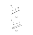
- FIG. 2 is a meridian cross-sectional view schematically showing the pneumatic tire of FIG. 3 (a) and 3 (b) are perspective views showing transponders that can be embedded in the pneumatic tire according to the present invention, respectively.
- FIG. 4 is an enlarged cross-sectional view of the transponder embedded in the pneumatic tire of FIG.
- FIG. 5 is a cross-sectional view showing a transponder embedded in a pneumatic tire in a state of being covered with a covering layer.
- 6 (a) to 6 (c) are plan views showing transponders embedded in a pneumatic tire in a state of being covered with a coating layer, respectively.
- FIG. 7 (a) and 7 (b) are plan views showing a transponder embedded in a pneumatic tire in a state of being covered with a coating layer, respectively.
- FIG. 8 is a cross-sectional view taken along the equatorial line schematically showing the pneumatic tire of FIG.
- FIG. 9 is a cross-sectional view taken along the meridian showing a modified example of the pneumatic tire according to the embodiment of the present invention.
- FIG. 10 is an explanatory diagram showing the tire radial position of the transponder in the test tire.
- FIGS. 1 to 8 show pneumatic tires according to the embodiment of the present invention.
- the pneumatic tire of the present embodiment includes a tread portion 1 extending in the tire circumferential direction to form an annular shape, a pair of sidewall portions 2 arranged on both sides of the tread portion 1, and these. It is provided with a pair of bead portions 3 arranged inside the sidewall portion 2 in the tire radial direction.
- At least one layer (one layer in FIG. 1) of the carcass layer 4 formed by arranging a plurality of reinforcing cords (carcass cords) in the radial direction is mounted between the pair of bead portions 3.
- An annular bead core 5 is embedded in each bead portion 3, and a bead filler 6 made of a rubber composition having a triangular cross section is arranged on the outer periphery of the bead core 5.
- the belt layer 7 includes a plurality of reinforcing cords that are inclined with respect to the tire circumferential direction, and the reinforcing cords are arranged so as to intersect each other between the layers.
- the inclination angle of the reinforcing cord with respect to the tire circumferential direction is set to, for example, in the range of 10 ° to 40 °.
- a steel cord is preferably used as the reinforcing cord of the belt layer 7.
- the belt cover layer 8 On the outer peripheral side of the tire of the belt layer 7, at least one layer (two layers in FIG. 1) in which reinforcing cords are arranged at an angle of, for example, 5 ° or less with respect to the tire circumferential direction for the purpose of improving high-speed durability.
- the belt cover layer 8 is arranged.
- the belt cover layer 8 located inside the tire radial direction constitutes a full cover covering the entire width of the belt layer 7, and the belt cover layer 8 located outside the tire radial direction covers only the end portion of the belt layer 7. It constitutes an edge cover layer.
- an organic fiber cord such as nylon or aramid is preferably used as the reinforcing cord of the belt cover layer 8.
- both terminals 4e of the carcass layer 4 are arranged so as to be folded back from the inside to the outside of each bead core 5 and to wrap the bead core 5 and the bead filler 6.
- the carcass layer 4 is wound around the bead core 5 in each bead portion 3 and the main body portion 4A, which is a portion extending from the tread portion 1 through each sidewall portion 2 to each bead portion 3, and is wound up on each sidewall portion 2 side. It includes a winding portion 4B which is a portion extending toward the direction.
- an inner liner layer 9 is arranged along the carcass layer 4.
- the cap tread rubber layer 11 is arranged on the tread portion 1
- the sidewall rubber layer 12 is arranged on the sidewall portion 2
- the rim cushion rubber layer 13 is arranged on the bead portion 3.
- the rubber layer 10 arranged on the outside of the carcass layer 4 in the sidewall portion 2 includes the sidewall rubber layer 12 and the rim cushion rubber layer 13.
- a transponder 20 is embedded between the winding portion 4B of the carcass layer 4 and the rubber layer 10. That is, the transponder 20 is arranged between the winding portion 4B of the carcass layer 4 and the sidewall rubber layer 12 or the rim cushion rubber layer 13 as an arrangement region in the tire width direction. Further, the transponder 20 has a position P1 15 mm outward in the tire radial direction from the upper end 5e (outer end portion 5e in the tire radial direction) of the bead core 5 and a tire diameter from the terminal 7e of the belt layer 7 as an arrangement region in the tire radial direction. It is arranged between the position P2 and the position P2 at 5 mm inside the direction. That is, the transponder 20 is arranged in the region S1 shown in FIG.
- the example in which the terminal 4e of the winding portion 4B of the carcass layer 4 is arranged in the middle of the sidewall portion 2 is shown.
- the terminal 4e of the winding portion 4B of the layer 4 can also be arranged on the side of the bead core 5.
- the transponder 20 is arranged between the bead filler 6 and the sidewall rubber layer 12 or the rim cushion rubber layer 13.
- the transponder 20 for example, an RFID (Radio Frequency Identification) tag can be used.
- the transponder 20 has a substrate 21 for storing data and an antenna 22 for transmitting and receiving data in a non-contact manner.
- RFID is an automatic recognition technology that is composed of a reader / writer having an antenna and a controller, and an ID tag having a substrate and an antenna, and can communicate data by a wireless method.
- the overall shape of the transponder 20 is not particularly limited, and for example, a columnar or plate-shaped transponder can be used as shown in FIGS. 3 (a) and 3 (b).
- a columnar or plate-shaped transponder can be used as shown in FIGS. 3 (a) and 3 (b).
- the transponder 20's antenna 22 protrudes from each of both ends of the substrate 21 and has a spiral shape.
- the communication property can be ensured by appropriately changing the length of the antenna 22.
- the carcass layer 4 is composed of a reinforcing cord (carcass cord) made of a polyester fiber cord.
- the reinforcing cord of the carcass layer 4 has a cutting elongation EB set in the range of 20% to 30%.
- the cutting elongation EB of the reinforcing cord of the carcass layer 4 is preferably in the range of 22% to 28%.
- the reinforcing cord of the carcass layer 4 used in the present invention has the same rigidity as the rayon fiber cord and has the characteristic that the hygroscopicity of the polyester fiber cord is low.
- the "cutting elongation” is measured at the time of cord cutting by conducting a tensile test under the conditions of a gripping interval of 250 mm and a tensile speed of 300 ⁇ 20 mm / min in accordance with the "chemical fiber tire cord test method" of JIS L1017.
- the elongation rate (%) of the sample code is measured at the time of cord cutting by conducting a tensile test under the conditions of a gripping interval of 250 mm and a tensile speed of 300 ⁇ 20 mm / min in accordance with the "chemical fiber tire cord test method" of JIS L1017.
- the elongation rate (%) of the sample code is measured at the time of cord cutting by conducting a tensile test under the conditions of a gripping interval of 250 mm and a tensile speed of 300 ⁇ 20 mm / min in accordance with the "chemical fiber tire cord test method" of JIS L1017.
- the type of fiber constituting the reinforcing cord (polyester fiber cord) of the carcass layer 4 is not particularly limited, but is polyethylene terephthalate fiber (PET fiber), polyethylene naphthalate fiber (PEN fiber), polybutylene terephthalate fiber (PBT), polybutylene. Naphthalate fiber (PBN) can be exemplified, and PET fiber is particularly preferable. Regardless of which fiber is used, good steering stability can be obtained depending on the physical characteristics of each fiber. In particular, in the case of PET fiber, since the PET fiber is inexpensive, it is possible to reduce the cost of the pneumatic tire. In addition, workability when manufacturing the cord can be improved.
- the carcass layer 4 is composed of a reinforcing cord made of a polyester fiber cord, and the cutting elongation EB of the reinforcing cord of the carcass layer 4 is in the range of 20% to 30%. It is possible to secure the same level of good steering stability as when using. Further, since the carcass layer 4 is made of a polyester fiber cord, it has low hygroscopicity, so that the communication property of the transponder 20 does not deteriorate as in the case of using a conventional rayon fiber cord.
- the transponder 20 is arranged between the position P1 15 mm outside the tire radial direction from the upper end 5e of the bead core 5 and the position P2 5 mm inside the tire radial direction from the terminal 7e of the belt layer 7, metal interference occurs. It is unlikely to occur, and the communicability of the transponder 20 can be sufficiently ensured. As a result, it is possible to improve the steering stability of the tire while ensuring the communication property of the transponder 20.
- the intermediate elongation of the reinforcing cord also tends to increase, the rigidity of the reinforcing cord decreases, and the steering stability of the tire deteriorates. ..
- the transponder 20 is arranged inside the tire radial direction from the position P1, metal interference with the rim flange occurs, and the communication property of the transponder 20 tends to deteriorate.
- metal interference with the belt layer 7 occurs, and the communication property of the transponder 20 tends to deteriorate.
- the transponder 20 may be arranged between the carcass layer 4 and the rubber layer 10 (sidewall rubber layer 12 or rim cushion rubber layer 13) while abutting against the rubber layer 10.
- the transponder 20 is arranged between the carcass layer 4 and the bead filler 6 even between the carcass layer 4 and the rubber layer 10 even between the carcass layer 4 and the rubber layer 10, the carcass line in the carcass layer 4 is disturbed and the steering stability of the tire is disturbed. Therefore, by providing the transponder 20 at the position in the tire width direction described above, the carcass line in the carcass layer 4 is not adversely affected, and the steering stability of the tire and the communication property of the transponder 20 are compatible. Can be done.
- the intermediate elongation EM of the reinforcing cord of the carcass layer 4 under a 1.0 cN / dtex load is preferably 5.0% or less, preferably in the range of 2.0% to 4.0%. It is more preferable to have.
- the rigidity of the tire can be sufficiently secured, and the steering stability on a dry road surface can be effectively improved. ..
- the intermediate elongation EM of the reinforcing cord of the carcass layer 4 under a load of 1.0 cN / dtex exceeds 5.0%, the rigidity cannot be sufficiently secured and the effect of improving the steering stability is limited.
- the "intermediate elongation under 1.0 cN / dtex load” is based on the "chemical fiber tire code test method" of JIS L1017, and the tensile test is performed under the conditions of a grip interval of 250 mm and a tensile speed of 300 ⁇ 20 mm / min. It is the elongation rate (%) of the sample code carried out and measured at the time of 1.0 cN / dtex load.
- the positive fineness CF of the reinforcing cord of the carcass layer 4 is preferably in the range of 4000 dtex to 8000 dtex, and more preferably in the range of 5000 dtex to 7000 dtex.
- the positive fineness CF of the reinforcing cord of the carcass layer 4 is less than 4000 dtex, it becomes difficult to sufficiently secure steering stability, and conversely, the positive fineness CF of the reinforcing cord of the carcass layer 4 exceeds 8000 dtex. And the ride quality tends to deteriorate.
- the twist coefficient CT represented by the following formula of the reinforcing cord of the dip-treated carcass layer 4 is preferably 2000 or more, and more preferably in the range of 2100 to 2400.
- the twist coefficient CT of the reinforcing cord of the carcass layer 4 is less than 2000, the rigidity may not be sufficiently secured and the effect of improving the steering stability may be limited.
- CT T ⁇ D 1/2
- T Number of twists of the reinforcing cord of the carcass layer (times / 10 cm)
- D Total fineness (dtex) of the reinforcing cord of the carcass layer
- the transponder 20 may be coated with a coating layer 23 made of an elastomer or rubber.
- the covering layer 23 covers the entire transponder 20 so as to sandwich both the front and back surfaces of the transponder 20.
- the coating layer 23 may be made of rubber having the same physical characteristics as the rubber constituting the sidewall rubber layer 12 or the rim cushion rubber layer 13, or may be made of rubber having different physical characteristics. Since the transponder 20 is protected by the coating layer 23 in this way, the durability of the transponder 20 can be improved.
- the cross-sectional shape of the covering layer 23 is not particularly limited, but for example, a triangle, a rectangle, a trapezoid, or a spindle can be adopted.
- the coating layer 23 is composed of rubber or an elastomer and a white filler of 20 phr or more.
- the relative permittivity of the coating layer 23 can be made relatively low as compared with the case where carbon is contained, and the communication property of the transponder 20 can be effectively improved.
- "phr” means a part by weight per 100 parts by weight of a rubber component (elastomer).
- the white filler constituting the coating layer 23 preferably contains 20 phr to 55 phr of calcium carbonate.
- the relative permittivity of the coating layer 23 can be made relatively low, and the communication property of the transponder 20 can be effectively improved.
- the white filler contains excessive calcium carbonate, it becomes brittle and the strength of the coating layer 23 decreases, which is not preferable.
- the coating layer 23 can optionally contain silica (white filler) of 20 phr or less and carbon black of 5 phr or less in addition to calcium carbonate. When a small amount of silica or carbon black is used in combination, the relative dielectric constant of the coating layer 23 can be lowered while ensuring the strength of the coating layer 23.
- the relative permittivity of the coating layer 23 is preferably 7 or less, and more preferably 2 to 5.
- the relative permittivity of the rubber constituting the coating layer 23 is a relative permittivity of 860 MHz to 960 MHz at room temperature.
- the room temperature conforms to the standard state of the JIS standard, and is 23 ⁇ 2 ° C. and 60% ⁇ 5% RH.
- the relative permittivity of the rubber is measured after being treated at 23 ° C. and 60% RH for 24 hours.
- the above-mentioned range of 860 MHz to 960 MHz corresponds to the current assigned frequency of RFID in the UHF band, but when the assigned frequency is changed, the relative permittivity of the range of the assigned frequency may be specified as described above.
- the total thickness Gac of the coating layer 23 and the maximum thickness Gar of the transponder 20 satisfy the relationship of 1.1 ⁇ Gac / Gar ⁇ 3.0.
- the total thickness Gac of the coating layer 23 is the total thickness of the coating layer 23 at the position including the transponder 20, and is the closest through the center C of the transponder 20 in the tire meridional cross section, for example, as shown in FIG. It is the total thickness on a straight line orthogonal to the carcass code of the carcass layer 4.
- the communication distance of the transponder 20 can be sufficiently secured.
- the above ratio is excessively small (the total thickness Gac of the coating layer 23 is excessively thin)
- the transponder 20 comes into contact with the adjacent rubber member, the resonance frequency shifts, and the communication property of the transponder 20 deteriorates.
- the above ratio is excessively large (the total thickness Gac of the coating layer 23 is excessively thick), the durability of the tire tends to deteriorate.
- the center C in the thickness direction of the transponder 20 is 25% to 75% of the total thickness Gac of the coating layer 23 from the surface on one side in the thickness direction of the coating layer 23. It is good if it is placed within the range of%. As a result, the transponder 20 is surely covered by the coating layer 23, so that the surrounding environment of the transponder 20 is stable, the resonance frequency does not deviate, and the communication distance of the transponder 20 can be sufficiently secured.
- the transponder 20 has a substrate 21 and antennas 22 extending from both ends of the substrate 21, and the transponder 20 is along the tire circumferential direction Tc. It is good if it is extended. More specifically, it is preferable that the transponder 20 has an inclination angle ⁇ with respect to the tire circumferential direction within a range of ⁇ 20 °. Further, the distance L between the terminal in the tire circumferential direction of the antenna 22 and the terminal in the tire circumferential direction of the covering layer 23 is preferably in the range of 2 mm to 20 mm. As a result, the entire transponder 20 is surely covered by the covering layer 23, so that the communication distance of the transponder 20 can be sufficiently secured.
- the durability of the transponder 20 is lowered against repeated tire deformation during running.
- the distance L between the terminal in the tire circumferential direction of the antenna 22 and the terminal in the tire circumferential direction of the covering layer 23 is smaller than 2 mm, the terminal in the tire circumferential direction of the antenna 22 protrudes from the covering layer 23 and is running. There is a risk that the antenna 22 will be damaged, and there is a concern that the communication distance after traveling will be shortened.
- the distance L is larger than 20 mm, a local weight increase occurs on the tire circumference, which causes deterioration of the tire balance.
- the transponder 20 has a substrate 21 and antennas 22 extending from both ends of the substrate 21, and at least one of the antennas 22 has a reference to the substrate 21. It may be extended so as to bend. In this case, it is preferable that each antenna 22 has an angle ⁇ with respect to the tire circumferential direction Tc within a range of ⁇ 20 °.
- the inclination angle ⁇ of the antenna 22 is an angle formed by a straight line connecting the base end and the tip end of the antenna 22 with respect to the tire circumferential direction.
- FIG. 8 shows the position Q of each splice portion in the tire circumferential direction.
- the center of the transponder 20 is arranged at a distance of 10 mm or more in the tire circumferential direction from the splice portion of the tire constituent member. That is, it is preferable that the transponder 20 is arranged in the region S2 shown in FIG. Specifically, it is preferable that the substrate 21 constituting the transponder 20 is separated from the position Q in the tire circumferential direction by 10 mm or more.
- the entire transponder 20 including the antenna 22 is separated from the position Q in the tire circumferential direction by 10 mm or more, and the entire transponder 20 in the state of being covered with the coated rubber is in the tire circumferential direction from the position Q. Most preferably, they are separated by 10 mm or more.
- the tire constituent member in which the splice portion is arranged apart from the transponder 20 may be a member adjacent to the transponder 20. Examples of such a tire component include a carcass layer 4, a bead filler 6, a sidewall rubber layer 12, and a rim cushion rubber layer 13.
- the positions Q of the splice portions of each tire component in the tire circumferential direction are arranged at equal intervals, but the present invention is not limited to this.
- the position Q in the tire circumferential direction can be set to any position, and in any case, the transponder 20 is arranged so as to be separated from the splice portion of each tire component by 10 mm or more in the tire circumferential direction.
- FIG. 9 shows a modified example of the pneumatic tire according to the embodiment of the present invention.
- the same objects as those in FIGS. 1 to 8 are designated by the same reference numerals, and detailed description of the portions thereof will be omitted.
- the transponder 20 is arranged between the carcass layer 4 and the inner liner layer 9.
- the tire component member in which the splice portion S is arranged apart from the transponder 20 may be a member adjacent to the transponder 20. Examples of such a tire component include a carcass layer 4 and an inner liner layer 9.
- a tread portion extending in the tire circumferential direction to form an annular shape, a pair of sidewall portions arranged on both sides of the tread portion, and these sidewall portions are arranged inside the tire radial direction.
- a pair of bead portions are provided, a bead filler is arranged on the outer periphery of the bead core of each bead portion, a carcass layer is mounted between the pair of bead portions, and a plurality of belt layers are mounted on the outer peripheral side of the carcass layer in the tread portion.
- an inner liner layer is arranged on the inner surface of the tire along the carcass layer, and the transponder is embedded in the pneumatic tire having a structure in which the carcass layer is wound around the bead core from the inside to the outside of the tire.
- Position tire width direction, tire radial direction and tire circumferential direction
- reinforcement cord of carcass layer (constituent material, cutting elongation EB, intermediate elongation EM, positive amount fineness CF and twist coefficient CT)
- coating layer Constituent material
- the position of the transponder corresponds to each position of A to C shown in FIG.
- the position of the transponder indicates the distance [mm] measured in the tire circumferential direction from the center of the transponder to the splice portion of the tire component.
- Durability (tire) Each test tire was assembled to a standard rim wheel, and a running test was conducted with a drum tester under the conditions of an air pressure of 120 kPa, 102% of the maximum load, and a running speed of 81 km. Was measured. The evaluation results are indicated by " ⁇ (excellent)” when the mileage reaches 6480 km, “ ⁇ (good)” when the mileage is 4050 km or more and less than 6480 km, and “ ⁇ (good)” when the mileage is less than 4050 km. ⁇ (possible) ”was shown in three stages.
- Communication For each test tire, communication work with the transponder was carried out using a reader / writer. Specifically, the longest distance that can be communicated with a reader / writer with an output of 250 mW and a carrier frequency of 860 MHz to 960 MHz was measured. The evaluation results are indicated by " ⁇ (excellent)” when the communication distance is 1000 mm or more, “ ⁇ (good)” when the communication distance is 500 mm or more and less than 1000 mm, and “ ⁇ (good)” when the communication distance is 250 mm or more and less than 500 mm. “ ⁇ (possible)” indicates that the communication distance is less than 250 mm, which is indicated by “ ⁇ (impossible)” in four stages.
- Comparative Example 1 the reinforcing cord of the carcass layer was composed of the rayon fiber cord, and the transponder was out of the range specified in the present invention in the radial direction of the tire, so that the communication property of the transponder deteriorated.
- Comparative Example 2 since the cutting elongation of the reinforcing cord of the carcass layer was set higher than the range specified in the present invention, the effect of improving the steering stability and durability of the tire was insufficient, and further, the transponder However, it was not possible to sufficiently secure the communication property of the transponder because it was out of the range specified in the present invention in the radial direction of the tire.
- Comparative Example 3 since the cutting elongation of the reinforcing cord of the carcass layer was set higher than the range specified in the present invention, the effect of improving the steering stability and durability of the tire was insufficient.
- Comparative Example 4 since the reinforcing cord of the carcass layer was composed of the rayon fiber cord, it was not possible to sufficiently secure the communication property of the transponder.
- Comparative Example 5 since the transponder was arranged between the carcass layer and the bead filler, the steering stability of the tire deteriorated, and further, since the reinforcing cord of the carcass layer was composed of the rayon fiber cord, the transponder Sufficient communication could not be ensured.
- Comparative Example 6 the transponder was arranged between the carcass layer and the bead filler, and the cutting elongation of the reinforcing cord of the carcass layer was set higher than the range specified in the present invention, so that the steering stability of the tire was set. The property deteriorated, and the effect of improving the durability of the tire was insufficient.
Landscapes
- Engineering & Computer Science (AREA)
- Mechanical Engineering (AREA)
- Tires In General (AREA)
Abstract
L'invention concerne un pneu permettant d'améliorer la stabilité de direction d'un pneu tout en garantissant la capacité de communication d'un transpondeur. Le pneu présente une structure dans laquelle une couche de carcasse 4 est enroulée autour de tringles 5 du côté intérieur au côté extérieur du pneu, la couche de carcasse 4 étant formée à l'aide de fils câblés de renfort comprenant des fils câblés de fibres de polyester, l'allongement à la rupture EB des fils câblés de renfort de la couche de carcasse 4 est dans la plage de 20 % à 30 %, et un transpondeur 20 est disposé entre une position P1 15 mm à partir d'une extrémité supérieure 5e de la tringle 5 sur le côté externe dans la direction radiale du pneu et une position P2 5 mm à partir d'une extrémité terminale 7e d'une couche de ceinture 7 sur le côté interne dans la direction radiale du pneu.
Priority Applications (3)
| Application Number | Priority Date | Filing Date | Title |
|---|---|---|---|
| DE112021002256.3T DE112021002256T5 (de) | 2020-06-29 | 2021-06-22 | Luftreifen |
| US18/002,895 US20230264524A1 (en) | 2020-06-29 | 2021-06-22 | Pneumatic tire |
| CN202180042806.5A CN115768635A (zh) | 2020-06-29 | 2021-06-22 | 充气轮胎 |
Applications Claiming Priority (2)
| Application Number | Priority Date | Filing Date | Title |
|---|---|---|---|
| JP2020111377A JP7410404B2 (ja) | 2020-06-29 | 2020-06-29 | 空気入りタイヤ |
| JP2020-111377 | 2020-06-29 |
Publications (1)
| Publication Number | Publication Date |
|---|---|
| WO2022004479A1 true WO2022004479A1 (fr) | 2022-01-06 |
Family
ID=79316269
Family Applications (1)
| Application Number | Title | Priority Date | Filing Date |
|---|---|---|---|
| PCT/JP2021/023535 Ceased WO2022004479A1 (fr) | 2020-06-29 | 2021-06-22 | Pneu |
Country Status (5)
| Country | Link |
|---|---|
| US (1) | US20230264524A1 (fr) |
| JP (1) | JP7410404B2 (fr) |
| CN (1) | CN115768635A (fr) |
| DE (1) | DE112021002256T5 (fr) |
| WO (1) | WO2022004479A1 (fr) |
Families Citing this family (3)
| Publication number | Priority date | Publication date | Assignee | Title |
|---|---|---|---|---|
| JP7770263B2 (ja) * | 2022-07-07 | 2025-11-14 | 株式会社ブリヂストン | タイヤ |
| IT202300023478A1 (it) * | 2023-11-08 | 2025-05-08 | Bridgestone Europe Nv Sa | Pneumatico provvisto di un dispositivo elettronico e corrispondente metodo di produzione |
| IT202300023475A1 (it) * | 2023-11-08 | 2025-05-08 | Bridgestone Europe Nv Sa | Pneumatico provvisto di un dispositivo elettronico e corrispondente metodo di produzione |
Citations (7)
| Publication number | Priority date | Publication date | Assignee | Title |
|---|---|---|---|---|
| US4911217A (en) * | 1989-03-24 | 1990-03-27 | The Goodyear Tire & Rubber Company | Integrated circuit transponder in a pneumatic tire for tire identification |
| JP2000108621A (ja) * | 1998-10-01 | 2000-04-18 | Yokohama Rubber Co Ltd:The | 重荷重用空気入りラジアルタイヤ |
| JP2003306007A (ja) * | 2002-04-11 | 2003-10-28 | Sumitomo Rubber Ind Ltd | タイヤ用ゴム付きファブリック、その製造方法及び空気入りタイヤ |
| JP2013530874A (ja) * | 2010-07-08 | 2013-08-01 | コンパニー ゼネラール デ エタブリッスマン ミシュラン | 無線周波トランスポンダ |
| JP2013541246A (ja) * | 2010-08-11 | 2013-11-07 | コンパニー ゼネラール デ エタブリッスマン ミシュラン | タイヤ中の電子装置用のアンテナの製造方法 |
| JP2019156070A (ja) * | 2018-03-09 | 2019-09-19 | 横浜ゴム株式会社 | 空気入りタイヤ |
| JP6683287B1 (ja) * | 2019-11-27 | 2020-04-15 | 横浜ゴム株式会社 | 空気入りタイヤ |
Family Cites Families (10)
| Publication number | Priority date | Publication date | Assignee | Title |
|---|---|---|---|---|
| US491127A (en) * | 1893-02-07 | Jib-crane | ||
| JP3397402B2 (ja) | 1993-11-19 | 2003-04-14 | 株式会社ブリヂストン | トランスポンダを内蔵した空気入りタイヤ |
| US7009576B2 (en) * | 2002-06-11 | 2006-03-07 | Michelin Recherche Et Technique S.A. | Radio frequency antenna for a tire and method for same |
| US20040159383A1 (en) * | 2002-06-11 | 2004-08-19 | Adamson John David | Method for embedding a radio frequency antenna in a tire, and an antenna for embedding in a tire |
| JP6681479B2 (ja) * | 2016-04-19 | 2020-04-15 | ブリヂストン アメリカズ タイヤ オペレーションズ、 エルエルシー | 補強コードアンテナを有する電子デバイスを備えたタイヤ |
| FR3059605A1 (fr) * | 2016-12-05 | 2018-06-08 | Compagnie Generale Des Etablissements Michelin | Enveloppe pneumatique equipee d''un organe electronique |
| FR3067976B1 (fr) * | 2017-06-22 | 2019-07-26 | Compagnie Generale Des Etablissements Michelin | Pneumatique adapte pour roulage a plat equipe d'un organe electronique |
| EP3677452B1 (fr) * | 2017-09-12 | 2023-04-19 | Sumitomo Rubber Industries, Ltd. | Pneumatique |
| JP7149152B2 (ja) * | 2018-10-03 | 2022-10-06 | Toyo Tire株式会社 | タイヤ |
| IT201900001565A1 (it) * | 2019-02-04 | 2020-08-04 | Bridgestone Europe Nv Sa | Pneumatico provvisto di un transponder |
-
2020
- 2020-06-29 JP JP2020111377A patent/JP7410404B2/ja active Active
-
2021
- 2021-06-22 US US18/002,895 patent/US20230264524A1/en active Pending
- 2021-06-22 DE DE112021002256.3T patent/DE112021002256T5/de active Pending
- 2021-06-22 CN CN202180042806.5A patent/CN115768635A/zh active Pending
- 2021-06-22 WO PCT/JP2021/023535 patent/WO2022004479A1/fr not_active Ceased
Patent Citations (7)
| Publication number | Priority date | Publication date | Assignee | Title |
|---|---|---|---|---|
| US4911217A (en) * | 1989-03-24 | 1990-03-27 | The Goodyear Tire & Rubber Company | Integrated circuit transponder in a pneumatic tire for tire identification |
| JP2000108621A (ja) * | 1998-10-01 | 2000-04-18 | Yokohama Rubber Co Ltd:The | 重荷重用空気入りラジアルタイヤ |
| JP2003306007A (ja) * | 2002-04-11 | 2003-10-28 | Sumitomo Rubber Ind Ltd | タイヤ用ゴム付きファブリック、その製造方法及び空気入りタイヤ |
| JP2013530874A (ja) * | 2010-07-08 | 2013-08-01 | コンパニー ゼネラール デ エタブリッスマン ミシュラン | 無線周波トランスポンダ |
| JP2013541246A (ja) * | 2010-08-11 | 2013-11-07 | コンパニー ゼネラール デ エタブリッスマン ミシュラン | タイヤ中の電子装置用のアンテナの製造方法 |
| JP2019156070A (ja) * | 2018-03-09 | 2019-09-19 | 横浜ゴム株式会社 | 空気入りタイヤ |
| JP6683287B1 (ja) * | 2019-11-27 | 2020-04-15 | 横浜ゴム株式会社 | 空気入りタイヤ |
Also Published As
| Publication number | Publication date |
|---|---|
| DE112021002256T5 (de) | 2023-03-02 |
| CN115768635A (zh) | 2023-03-07 |
| US20230264524A1 (en) | 2023-08-24 |
| JP7410404B2 (ja) | 2024-01-10 |
| JP2022010681A (ja) | 2022-01-17 |
Similar Documents
| Publication | Publication Date | Title |
|---|---|---|
| WO2021106916A1 (fr) | Bandage pneumatique | |
| JP6667045B1 (ja) | 空気入りタイヤ | |
| WO2022004477A1 (fr) | Pneumatique | |
| JP7842523B2 (ja) | 空気入りタイヤ | |
| WO2021106917A1 (fr) | Pneumatique | |
| JP2021127087A (ja) | 空気入りタイヤ | |
| WO2022004479A1 (fr) | Pneu | |
| JP7343784B2 (ja) | 空気入りタイヤ | |
| WO2021166792A1 (fr) | Pneumatique | |
| JP2021112932A (ja) | 空気入りタイヤ | |
| JP2021127073A (ja) | 空気入りタイヤ | |
| WO2021241202A1 (fr) | Pneu | |
| JP7343786B2 (ja) | 空気入りタイヤ | |
| JP2021127093A (ja) | 空気入りタイヤ | |
| JP2021127092A (ja) | 空気入りタイヤ | |
| WO2021241203A1 (fr) | Pneumatique | |
| JP7279671B2 (ja) | 空気入りタイヤ | |
| JP7469605B2 (ja) | 空気入りタイヤ | |
| JP7469606B2 (ja) | 空気入りタイヤ | |
| JP2021187267A (ja) | 空気入りタイヤ | |
| WO2021166798A1 (fr) | Bandage pneumatique | |
| WO2021166794A1 (fr) | Pneumatique | |
| JP7457250B2 (ja) | 空気入りタイヤ | |
| WO2021166793A1 (fr) | Pneumatique | |
| JP7842524B2 (ja) | 空気入りタイヤ |
Legal Events
| Date | Code | Title | Description |
|---|---|---|---|
| 121 | Ep: the epo has been informed by wipo that ep was designated in this application |
Ref document number: 21833020 Country of ref document: EP Kind code of ref document: A1 |
|
| 122 | Ep: pct application non-entry in european phase |
Ref document number: 21833020 Country of ref document: EP Kind code of ref document: A1 |