WO2022004582A1 - 耐熱容器 - Google Patents
耐熱容器 Download PDFInfo
- Publication number
- WO2022004582A1 WO2022004582A1 PCT/JP2021/024102 JP2021024102W WO2022004582A1 WO 2022004582 A1 WO2022004582 A1 WO 2022004582A1 JP 2021024102 W JP2021024102 W JP 2021024102W WO 2022004582 A1 WO2022004582 A1 WO 2022004582A1
- Authority
- WO
- WIPO (PCT)
- Prior art keywords
- wall portion
- wall
- heat
- resistant container
- pores
- Prior art date
- Legal status (The legal status is an assumption and is not a legal conclusion. Google has not performed a legal analysis and makes no representation as to the accuracy of the status listed.)
- Ceased
Links
Images



Classifications
-
- B—PERFORMING OPERATIONS; TRANSPORTING
- B65—CONVEYING; PACKING; STORING; HANDLING THIN OR FILAMENTARY MATERIAL
- B65D—CONTAINERS FOR STORAGE OR TRANSPORT OF ARTICLES OR MATERIALS, e.g. BAGS, BARRELS, BOTTLES, BOXES, CANS, CARTONS, CRATES, DRUMS, JARS, TANKS, HOPPERS, FORWARDING CONTAINERS; ACCESSORIES, CLOSURES, OR FITTINGS THEREFOR; PACKAGING ELEMENTS; PACKAGES
- B65D81/00—Containers, packaging elements, or packages, for contents presenting particular transport or storage problems, or adapted to be used for non-packaging purposes after removal of contents
- B65D81/38—Containers, packaging elements, or packages, for contents presenting particular transport or storage problems, or adapted to be used for non-packaging purposes after removal of contents with thermal insulation
- B65D81/3813—Containers, packaging elements, or packages, for contents presenting particular transport or storage problems, or adapted to be used for non-packaging purposes after removal of contents with thermal insulation rigid container being in the form of a box, tray or like container
-
- C—CHEMISTRY; METALLURGY
- C04—CEMENTS; CONCRETE; ARTIFICIAL STONE; CERAMICS; REFRACTORIES
- C04B—LIME, MAGNESIA; SLAG; CEMENTS; COMPOSITIONS THEREOF, e.g. MORTARS, CONCRETE OR LIKE BUILDING MATERIALS; ARTIFICIAL STONE; CERAMICS; REFRACTORIES; TREATMENT OF NATURAL STONE
- C04B35/00—Shaped ceramic products characterised by their composition; Ceramics compositions; Processing powders of inorganic compounds preparatory to the manufacturing of ceramic products
- C04B35/01—Shaped ceramic products characterised by their composition; Ceramics compositions; Processing powders of inorganic compounds preparatory to the manufacturing of ceramic products based on oxide ceramics
- C04B35/10—Shaped ceramic products characterised by their composition; Ceramics compositions; Processing powders of inorganic compounds preparatory to the manufacturing of ceramic products based on oxide ceramics based on aluminium oxide
- C04B35/111—Fine ceramics
-
- C—CHEMISTRY; METALLURGY
- C04—CEMENTS; CONCRETE; ARTIFICIAL STONE; CERAMICS; REFRACTORIES
- C04B—LIME, MAGNESIA; SLAG; CEMENTS; COMPOSITIONS THEREOF, e.g. MORTARS, CONCRETE OR LIKE BUILDING MATERIALS; ARTIFICIAL STONE; CERAMICS; REFRACTORIES; TREATMENT OF NATURAL STONE
- C04B35/00—Shaped ceramic products characterised by their composition; Ceramics compositions; Processing powders of inorganic compounds preparatory to the manufacturing of ceramic products
- C04B35/01—Shaped ceramic products characterised by their composition; Ceramics compositions; Processing powders of inorganic compounds preparatory to the manufacturing of ceramic products based on oxide ceramics
- C04B35/10—Shaped ceramic products characterised by their composition; Ceramics compositions; Processing powders of inorganic compounds preparatory to the manufacturing of ceramic products based on oxide ceramics based on aluminium oxide
-
- C—CHEMISTRY; METALLURGY
- C04—CEMENTS; CONCRETE; ARTIFICIAL STONE; CERAMICS; REFRACTORIES
- C04B—LIME, MAGNESIA; SLAG; CEMENTS; COMPOSITIONS THEREOF, e.g. MORTARS, CONCRETE OR LIKE BUILDING MATERIALS; ARTIFICIAL STONE; CERAMICS; REFRACTORIES; TREATMENT OF NATURAL STONE
- C04B38/00—Porous mortars, concrete, artificial stone or ceramic ware; Preparation thereof
- C04B38/007—Porous mortars, concrete, artificial stone or ceramic ware; Preparation thereof characterised by the pore distribution, e.g. inhomogeneous distribution of pores
- C04B38/0074—Porous mortars, concrete, artificial stone or ceramic ware; Preparation thereof characterised by the pore distribution, e.g. inhomogeneous distribution of pores expressed as porosity percentage
-
- C—CHEMISTRY; METALLURGY
- C04—CEMENTS; CONCRETE; ARTIFICIAL STONE; CERAMICS; REFRACTORIES
- C04B—LIME, MAGNESIA; SLAG; CEMENTS; COMPOSITIONS THEREOF, e.g. MORTARS, CONCRETE OR LIKE BUILDING MATERIALS; ARTIFICIAL STONE; CERAMICS; REFRACTORIES; TREATMENT OF NATURAL STONE
- C04B2111/00—Mortars, concrete or artificial stone or mixtures to prepare them, characterised by specific function, property or use
- C04B2111/00241—Physical properties of the materials not provided for elsewhere in C04B2111/00
- C04B2111/00413—Materials having an inhomogeneous concentration of ingredients or irregular properties in different layers
-
- C—CHEMISTRY; METALLURGY
- C04—CEMENTS; CONCRETE; ARTIFICIAL STONE; CERAMICS; REFRACTORIES
- C04B—LIME, MAGNESIA; SLAG; CEMENTS; COMPOSITIONS THEREOF, e.g. MORTARS, CONCRETE OR LIKE BUILDING MATERIALS; ARTIFICIAL STONE; CERAMICS; REFRACTORIES; TREATMENT OF NATURAL STONE
- C04B2235/00—Aspects relating to ceramic starting mixtures or sintered ceramic products
- C04B2235/02—Composition of constituents of the starting material or of secondary phases of the final product
- C04B2235/30—Constituents and secondary phases not being of a fibrous nature
- C04B2235/32—Metal oxides, mixed metal oxides, or oxide-forming salts thereof, e.g. carbonates, nitrates, (oxy)hydroxides, chlorides
- C04B2235/3205—Alkaline earth oxides or oxide forming salts thereof, e.g. beryllium oxide
- C04B2235/3206—Magnesium oxides or oxide-forming salts thereof
-
- C—CHEMISTRY; METALLURGY
- C04—CEMENTS; CONCRETE; ARTIFICIAL STONE; CERAMICS; REFRACTORIES
- C04B—LIME, MAGNESIA; SLAG; CEMENTS; COMPOSITIONS THEREOF, e.g. MORTARS, CONCRETE OR LIKE BUILDING MATERIALS; ARTIFICIAL STONE; CERAMICS; REFRACTORIES; TREATMENT OF NATURAL STONE
- C04B2235/00—Aspects relating to ceramic starting mixtures or sintered ceramic products
- C04B2235/02—Composition of constituents of the starting material or of secondary phases of the final product
- C04B2235/30—Constituents and secondary phases not being of a fibrous nature
- C04B2235/32—Metal oxides, mixed metal oxides, or oxide-forming salts thereof, e.g. carbonates, nitrates, (oxy)hydroxides, chlorides
- C04B2235/3205—Alkaline earth oxides or oxide forming salts thereof, e.g. beryllium oxide
- C04B2235/3208—Calcium oxide or oxide-forming salts thereof, e.g. lime
-
- C—CHEMISTRY; METALLURGY
- C04—CEMENTS; CONCRETE; ARTIFICIAL STONE; CERAMICS; REFRACTORIES
- C04B—LIME, MAGNESIA; SLAG; CEMENTS; COMPOSITIONS THEREOF, e.g. MORTARS, CONCRETE OR LIKE BUILDING MATERIALS; ARTIFICIAL STONE; CERAMICS; REFRACTORIES; TREATMENT OF NATURAL STONE
- C04B2235/00—Aspects relating to ceramic starting mixtures or sintered ceramic products
- C04B2235/02—Composition of constituents of the starting material or of secondary phases of the final product
- C04B2235/30—Constituents and secondary phases not being of a fibrous nature
- C04B2235/32—Metal oxides, mixed metal oxides, or oxide-forming salts thereof, e.g. carbonates, nitrates, (oxy)hydroxides, chlorides
- C04B2235/3217—Aluminum oxide or oxide forming salts thereof, e.g. bauxite, alpha-alumina
-
- C—CHEMISTRY; METALLURGY
- C04—CEMENTS; CONCRETE; ARTIFICIAL STONE; CERAMICS; REFRACTORIES
- C04B—LIME, MAGNESIA; SLAG; CEMENTS; COMPOSITIONS THEREOF, e.g. MORTARS, CONCRETE OR LIKE BUILDING MATERIALS; ARTIFICIAL STONE; CERAMICS; REFRACTORIES; TREATMENT OF NATURAL STONE
- C04B2235/00—Aspects relating to ceramic starting mixtures or sintered ceramic products
- C04B2235/02—Composition of constituents of the starting material or of secondary phases of the final product
- C04B2235/30—Constituents and secondary phases not being of a fibrous nature
- C04B2235/34—Non-metal oxides, non-metal mixed oxides, or salts thereof that form the non-metal oxides upon heating, e.g. carbonates, nitrates, (oxy)hydroxides, chlorides
- C04B2235/3418—Silicon oxide, silicic acids or oxide forming salts thereof, e.g. silica sol, fused silica, silica fume, cristobalite, quartz or flint
-
- C—CHEMISTRY; METALLURGY
- C04—CEMENTS; CONCRETE; ARTIFICIAL STONE; CERAMICS; REFRACTORIES
- C04B—LIME, MAGNESIA; SLAG; CEMENTS; COMPOSITIONS THEREOF, e.g. MORTARS, CONCRETE OR LIKE BUILDING MATERIALS; ARTIFICIAL STONE; CERAMICS; REFRACTORIES; TREATMENT OF NATURAL STONE
- C04B2235/00—Aspects relating to ceramic starting mixtures or sintered ceramic products
- C04B2235/02—Composition of constituents of the starting material or of secondary phases of the final product
- C04B2235/30—Constituents and secondary phases not being of a fibrous nature
- C04B2235/44—Metal salt constituents or additives chosen for the nature of the anions, e.g. hydrides or acetylacetonate
- C04B2235/442—Carbonates
-
- C—CHEMISTRY; METALLURGY
- C04—CEMENTS; CONCRETE; ARTIFICIAL STONE; CERAMICS; REFRACTORIES
- C04B—LIME, MAGNESIA; SLAG; CEMENTS; COMPOSITIONS THEREOF, e.g. MORTARS, CONCRETE OR LIKE BUILDING MATERIALS; ARTIFICIAL STONE; CERAMICS; REFRACTORIES; TREATMENT OF NATURAL STONE
- C04B2235/00—Aspects relating to ceramic starting mixtures or sintered ceramic products
- C04B2235/70—Aspects relating to sintered or melt-casted ceramic products
- C04B2235/74—Physical characteristics
- C04B2235/77—Density
-
- C—CHEMISTRY; METALLURGY
- C04—CEMENTS; CONCRETE; ARTIFICIAL STONE; CERAMICS; REFRACTORIES
- C04B—LIME, MAGNESIA; SLAG; CEMENTS; COMPOSITIONS THEREOF, e.g. MORTARS, CONCRETE OR LIKE BUILDING MATERIALS; ARTIFICIAL STONE; CERAMICS; REFRACTORIES; TREATMENT OF NATURAL STONE
- C04B2235/00—Aspects relating to ceramic starting mixtures or sintered ceramic products
- C04B2235/70—Aspects relating to sintered or melt-casted ceramic products
- C04B2235/74—Physical characteristics
- C04B2235/77—Density
- C04B2235/775—Products showing a density-gradient
-
- C—CHEMISTRY; METALLURGY
- C04—CEMENTS; CONCRETE; ARTIFICIAL STONE; CERAMICS; REFRACTORIES
- C04B—LIME, MAGNESIA; SLAG; CEMENTS; COMPOSITIONS THEREOF, e.g. MORTARS, CONCRETE OR LIKE BUILDING MATERIALS; ARTIFICIAL STONE; CERAMICS; REFRACTORIES; TREATMENT OF NATURAL STONE
- C04B2235/00—Aspects relating to ceramic starting mixtures or sintered ceramic products
- C04B2235/70—Aspects relating to sintered or melt-casted ceramic products
- C04B2235/94—Products characterised by their shape
-
- C—CHEMISTRY; METALLURGY
- C04—CEMENTS; CONCRETE; ARTIFICIAL STONE; CERAMICS; REFRACTORIES
- C04B—LIME, MAGNESIA; SLAG; CEMENTS; COMPOSITIONS THEREOF, e.g. MORTARS, CONCRETE OR LIKE BUILDING MATERIALS; ARTIFICIAL STONE; CERAMICS; REFRACTORIES; TREATMENT OF NATURAL STONE
- C04B2235/00—Aspects relating to ceramic starting mixtures or sintered ceramic products
- C04B2235/70—Aspects relating to sintered or melt-casted ceramic products
- C04B2235/95—Products characterised by their size, e.g. microceramics
-
- C—CHEMISTRY; METALLURGY
- C04—CEMENTS; CONCRETE; ARTIFICIAL STONE; CERAMICS; REFRACTORIES
- C04B—LIME, MAGNESIA; SLAG; CEMENTS; COMPOSITIONS THEREOF, e.g. MORTARS, CONCRETE OR LIKE BUILDING MATERIALS; ARTIFICIAL STONE; CERAMICS; REFRACTORIES; TREATMENT OF NATURAL STONE
- C04B35/00—Shaped ceramic products characterised by their composition; Ceramics compositions; Processing powders of inorganic compounds preparatory to the manufacturing of ceramic products
- C04B35/622—Forming processes; Processing powders of inorganic compounds preparatory to the manufacturing of ceramic products
- C04B35/626—Preparing or treating the powders individually or as batches ; preparing or treating macroscopic reinforcing agents for ceramic products, e.g. fibres; mechanical aspects section B
- C04B35/62605—Treating the starting powders individually or as mixtures
- C04B35/62625—Wet mixtures
- C04B35/6263—Wet mixtures characterised by their solids loadings, i.e. the percentage of solids
Definitions
- This disclosure relates to heat-resistant containers.
- Ceramics are widely used for heat-resistant containers from the viewpoint of insulation and heat resistance.
- the heat-resistant container includes a first wall portion constituting a side wall and a second wall portion constituting an upper wall or a bottom wall.
- the first wall portion and the second wall portion are made of ceramics.
- the first wall portion has a large number of pores inside.
- the pore ratio in the cross section orthogonal to the wall surface of the first wall portion and parallel to the height direction of the first wall portion is set to Pr1, and among the cross sections of the first wall portion.
- Pr2 the pore ratio in the cross section orthogonal to the wall surface of the first wall portion and parallel to the width direction of the first wall portion.
- FIG. 1 is a schematic perspective view of a heat-resistant container according to an embodiment.
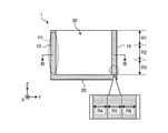
- FIG. 2 is a vertical sectional view of the heat-resistant container according to the embodiment.
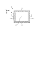
- FIG. 3 is a cross-sectional view of the heat-resistant container according to the embodiment.
- FIG. 4 is a schematic enlarged view of the H1 portion shown in FIG.
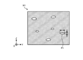
- FIG. 5 is a schematic enlarged view of the H2 portion shown in FIG.
- FIG. 6 is an observation photograph of the vertical cross section of the first wall portion of the heat-resistant container according to the embodiment.
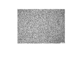
- FIG. 7 is an observation photograph of the cross section of the first wall portion of the heat-resistant container according to the embodiment.
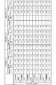
- FIG. 8 is a table showing the measurement results of the aspect ratio, porosity, distance between the centers of gravity, circularity, and equivalent circle diameter in the vertical cross section of the first wall portion.
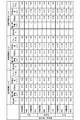
- FIG. 9 is a table showing the measurement results of the aspect ratio, porosity, distance between the centers of gravity, circularity, and equivalent circle diameter in the cross section of the first wall portion.
- a heat-resistant container made of ceramic having excellent heat-impact resistance such as a ceramic member exposed to high-temperature molten metal and a member used for a combustion chamber wall of an internal combustion engine or a fuel injection nozzle, is desired.
- the present disclosure has been made in view of the above, and provides a heat-resistant container having excellent heat-resistant impact resistance.
- FIG. 1 is a schematic perspective view of the heat-resistant container according to the embodiment. Further, FIG. 2 is a vertical sectional view of the heat-resistant container according to the embodiment, and FIG. 3 is a cross-sectional view of the heat-resistant container according to the embodiment.
- the heat-resistant container 1 has a plurality of (here, four) first wall portions 10 and a second wall portion 20. Further, the heat-resistant container 1 has an opening 30 on the side opposite to the second wall portion 20.
- the second wall portion 20 constitutes the bottom wall of the heat-resistant container 1.
- the second wall portion 20 constitutes the bottom wall of the heat-resistant container 1, but the second wall portion 20 is not limited to this, and constitutes the upper wall of the heat-resistant container 1. May be good. That is, the heat-resistant container 1 may be upside down from the state shown in FIG.
- the second wall portion 20 has a rectangular shape in a plan view (see FIG. 3).
- the square shape is not limited to the rectangle as shown in FIG. 3, and may be a square shape.
- the four first wall portions 10 form a side wall of the heat-resistant container 1 and are connected to the second wall portion 20.
- the shape of the second wall portion 20 in a plan view is not limited to a square shape, and may be, for example, a circular shape.
- the heat-resistant container 1 contains a high-temperature substance.
- the heat-resistant container 1 may be used as a container for molten metal.
- the molten metal is poured into the heat-resistant container 1 from above, that is, from the opening 30.
- the heat-resistant container 1 is not limited to this, and may be used as a radle for scooping up molten metal, for example.
- the height direction of the first wall portion 10 and "the width direction of the first wall portion 10".
- the “height direction of the first wall portion 10” means the Z-axis direction, that is, the direction from one of the second wall portion 20 and the opening 30 toward the other.
- the "width direction of the first wall portion 10” means a direction from one of the two adjacent first wall portions 10 toward the other.
- the width direction of the first wall portion 10 whose wall surface is orthogonal to the X-axis direction corresponds to the Y-axis direction
- the width direction of the first wall portion 10 whose wall surface is orthogonal to the Y-axis direction corresponds to the X-axis direction. do.
- FIG. 2 shows a cross section of the heat-resistant container 1 orthogonal to the wall surface of the first wall portion 10 and parallel to the height direction of the first wall portion 10.
- FIG. 3 shows a cross section of the heat-resistant container 1 orthogonal to the wall surface of the first wall portion 10 and parallel to the width direction of the first wall portion 10.
- the region closest to the opening 30 is defined as the upper portion R1 of the first wall portion 10, and the region closest to the second wall portion 20. Is the lower part R3 of the first wall portion 10. Further, the region between the upper portion R1 and the lower portion R3 of the first wall portion 10 is defined as the central portion R2 among the three equal parts of the first wall portion 10 in the height direction.
- the region closest to the inside of the heat-resistant container 1, that is, the region on the inner wall surface side of the first wall portion 10, which is obtained by dividing the first wall portion 10 into three equal parts in the thickness direction, is the region of the first wall portion 10.
- the inner wall surface side portion R4 the region closest to the outside of the heat-resistant container 1 of the first wall portion 10 divided into three equal parts in the thickness direction, that is, the region on the outer wall surface side of the first wall portion 10 is the outer wall surface side portion R6 of the first wall portion 10.
- the region between the inner wall surface side portion R4 and the outer wall surface side portion R6 of the first wall portion 10 is defined as the inner R5.
- the heat-resistant container 1 is made of ceramics.
- the ceramics constituting the heat-resistant container 1 are, for example, aluminum oxide ceramics, silicon nitride ceramics, aluminum nitride ceramics, silicon carbide ceramics and the like.
- the heat-resistant container 1 When the heat-resistant container 1 is made of aluminum oxide ceramics, it has excellent mechanical properties among the ceramics, although it is relatively inexpensive including the raw material price and the manufacturing cost. Further, the heat-resistant container 1 made of aluminum oxide ceramics has a low risk of contaminating the natural environment when it is disposed of.
- the aluminum oxide ceramics contain 70% by mass or more of aluminum oxide out of 100% by mass of all the components constituting the ceramics.
- the material of the heat-resistant container 1 can be confirmed by, for example, the following method.
- the target heat-resistant container 1 is measured using an X-ray diffractometer (XRD), and the obtained 2 ⁇ (2 ⁇ is a diffraction angle) is collated with the JCPDS card.
- quantitative analysis of aluminum (Al) is performed using an ICP emission spectroscopic analyzer (ICP) or a fluorescent X-ray analyzer (XRF). If the content of Al converted from the Al content measured by ICP or XRF into aluminum oxide (Al 2 O 3 ) is 70% by mass or more, the material of the heat-resistant container 1 is aluminum oxide ceramics. ..
- FIG. 4 is a schematic enlarged view of the H1 portion shown in FIG.
- FIG. 5 is a schematic enlarged view of the H2 portion shown in FIG.
- the pores appearing in the cross section shown in FIG. 4 that is, the pores orthogonal to the wall surface of the first wall portion 10 and parallel to the height direction of the first wall portion 10 (see FIG. 2) are referred to as “P1”.
- the porosity in such a cross section is "Pr1”.
- the pores appearing in the cross section shown in FIG. 5, that is, the cross section orthogonal to the wall surface of the first wall portion 10 and parallel to the width direction of the first wall portion 10 (see FIG. 3) are referred to as "P2”.
- the porosity in the cross section is defined as "Pr2".
- FIG. 4 only one of a large number of pores P1 is designated. This also applies to FIG.
- the porosity Pr1 is smaller than Pr2.
- a thermal shock will be applied to the ceramic container.
- heat is transferred along the wall surface of the container, and heat is also transferred from the surface of the container to the inside.
- heat is easily transferred from the surface of the ceramic container to the inside, cracks are likely to occur inside the ceramic container due to thermal shock. Therefore, it is preferable to make it relatively easy to transfer the generated heat along the wall surface of the ceramic container. If the porosity Pr1 (see FIGS. 2 and 4) is smaller than the porosity Pr2 (see FIGS.
- the heat-resistant container 1 according to the embodiment is less likely to have cracks inside the first wall portion 10, that is, has excellent heat-resistant impact resistance.
- the ceramics constituting the heat-resistant container 1 according to the embodiment are dense ceramics.
- the dense ceramic is a ceramic having a porosity Pr1 and Pr2 of about 17% or less.
- the porosity Pr1 and Pr2 of the first wall portion 10 according to the embodiment is 1% or more and 17% or less.
- the dense ceramics may be defined by the average value of the porosity Pr1 and Pr2. In this case, the average value of the porosities Pr1 and Pr2 is preferably 2% or more and 13% or less.
- the porosity Pr2 in the upper part R1 (see FIG. 2) of the first wall portion 10 is larger than the porosity Pr2 in the lower part R3 (see FIG. 2) of the first wall portion 10. ..
- the porosity Pr2 on the opening 30 side is larger than Pr2 on the second wall 20 side.
- the heat-resistant container 1 when used as a container for molten metal, about 60 to 70% of the total capacity of the heat-resistant container 1 may be charged with molten metal. That is, when the molten metal is put into the heat-resistant container 1, the lower part R3 of the first wall portion 10 always comes into contact with the molten metal, but the upper part R1 of the first wall portion 10 does not necessarily come into contact with the molten metal.
- the lower part R3 of the first wall portion 10, which is likely to come into contact with the molten metal, is required to have thermal shock resistance and mechanical strength. This is because, for example, it is necessary to withstand the weight of the contents such as molten metal.
- the upper portion R1 of the first wall portion 10 on the opening 30 side does not necessarily require mechanical strength, but requires particularly high thermal shock resistance.
- the porosity Pr2 on the opening 30 side of the first wall 10 is made larger than that on the second wall 20 side, so that the heat impact resistance on the opening 30 side is relative. Can be improved. This makes it possible to improve the heat-resistant impact resistance of the heat-resistant container 1 as a whole.
- the porosity Pr1 in the inner R5 (see FIG. 2) of the first wall portion 10 is the porosity Pr1 in the inner wall surface side portion R4 (see FIG. 2) of the first wall portion 10. Greater than.
- the heat-resistant impact resistance of the inner wall surface side portion R4 can be improved.
- the mechanical strength of the inner wall surface R5 can be improved as compared with the inner wall surface side portion R4, and the mechanical strength as a whole can be improved.
- the average value of the circle-equivalent diameter of the pore P1 (see FIG. 4) is defined as "Pd1"
- the average value of the circle-equivalent diameter of the pore P2 (see FIG. 5) is defined as "Pd2”.
- the average value Pd1 of the circle-equivalent diameter of the pore P1 is smaller than the average value Pd2 of the circle-equivalent diameter of the pore P2.
- the pores P1 are relatively difficult to transfer heat, and the heat is transmitted inside the heat-resistant container 1 so as to bypass the pores P1.
- a comparison of how heat is transferred around the pores P1 between the pores P1 having a small equivalent circle diameter and the pores P1 having a large diameter is as follows. That is, in the case of the pore P1 having a small equivalent circle diameter, heat is easily transferred to the ceramics around the pore P1, so that heat is easily transferred in the height direction of the first wall portion 10. On the other hand, in the case of the pore P1 having a large equivalent circle diameter, heat is not easily transferred to the ceramic around the pore P1, so that heat is not easily transferred in the thickness direction of the first wall portion 10. Thereby, the heat impact resistance of the heat resistant container 1 according to the embodiment can be improved.
- the average value of the distance between the centers of gravity of the pores P1 is defined as “Pw1”
- the average value of the distance between the centers of gravity of the pores P2 is defined as “Pw2”.
- the average value Pw2 of the distance between the centers of gravity of the pores P2 is shorter than the average value Pw1 of the distance between the centers of gravity of the pores P1.
- the "excluded area” means an area excluding pores smaller than a specific area. In other words, the "excluded area” means the area when only the pores having a specific area or more are measured.
- the exclusion area of 30 ⁇ m 2 means that only the pores having an area of 30 ⁇ m 2 or more are extracted and calculated.
- the average value of the aspect ratios of the pores P1 (see FIG. 4) in the upper part R1 (see FIG. 2) of the first wall portion 10 is Pa1
- the average value of the aspect ratios of the pores P2 (see FIG. 5) in the upper part R1 is Pa2.
- the average value Pa1 is smaller than the average value Pa2.
- the aspect ratio is the major axis divided by the minor axis in one pore.
- the major axis is the length of the longest portion of the pores of interest, and the minor axis is the length of the longest portion in the direction perpendicular to the major axis.
- the following can be considered as one of the reasons for the improvement in thermal shock resistance. That is, in general, the smaller the Young's modulus of ceramics, the better the thermal impact resistance.
- the Young's modulus decreases as the bulk density decreases.
- the mechanical strength may decrease. Therefore, if the aspect ratio of the pores is increased, the mechanical strength can be improved and the thermal impact resistance can be improved while keeping the bulk density low.
- the Young's modulus in the height direction of the first wall portion 10 can be reduced. If the Young's modulus in the height direction of the first wall portion 10 is small, it is possible to prevent cracks from developing in the height direction of the first wall portion 10. Therefore, the heat-resistant impact resistance of the heat-resistant container 1 can be improved.
- the following can be considered as one of the reasons for the improvement in thermal shock resistance. That is, since the upper portion R1 of the first wall portion 10 is open to the outside, it is easily deformed by thermal expansion due to the temperature change of the heat-resistant container 1. Therefore, even if the heat-resistant container 1 receives a thermal shock, the thermal stress in the thickness direction of the first wall portion 10 is reduced, and cracks in the upper portion R1 are likely to be suppressed. Therefore, even if the average value Pa2 of the aspect ratio of the pores P2 is reduced, the thermal impact resistance does not easily decrease. Rather, by reducing the average value Pa2 and making the pores P2 closer to a circle, the growth of cracks is suitably suppressed. be able to.
- the porosity Pr1, Pr2, the average values Pw1 and Pw2 of the distance between the centers of gravity, and the average values Pa1 and Pa2 of the aspect ratio are the pores P1 and P2 having a cross-sectional area of 30 ⁇ m 2 or more among the pores P1 and P2 appearing in the cross section, that is, It is preferable to measure the exclusion area as 30 ⁇ m 2. More preferably, the exclusion area is limited to 100 ⁇ m 2. More preferably, the exclusion area is limited to 150 ⁇ m 2.
- the upper limit of the cross-sectional area of the pores P1 and P2 is preferably 800 ⁇ m 2 or less. This is because if relatively large pores P1 and P2 having a cross-sectional area of more than 800 ⁇ m 2 are present, thermal stress is concentrated on the large pores P1 and P2, which may reduce the mechanical strength and thus the thermal shock resistance.
- the porosity Pr1 and Pr2 are preferably 1% or more and 14% or less. Further, the average values Pw1 and Pw2 of the distance between the centers of gravity are preferably 40 ⁇ m or more and 200 ⁇ m or less.
- alumina powder is mixed with silicon dioxide (SiO 2 ) powder, magnesium oxide (MgO) powder and calcium carbonate (CaCO 3 ) powder as known sintering aids, water is added, and wet pulverization is performed with a pulverizer. To prepare a primary slurry.
- the amount of the dispersant such as PAA (ammonium polyacrylate) solution is 0.02 parts by mass or more and 0.5 parts by mass or less with respect to 100 parts by mass of the raw material powder solid content.
- the inside of the first wall portion 10 is provided.
- the porosity Pr1 in the above can be made larger than the porosity Pr1 on the inner wall surface side of the first wall portion 10.
- an aqueous solution of, for example, polyvinyl alcohol, acrylic resin, polyethylene glycol or the like as a known organic binder (binder) is added to the primary slurry and mixed to prepare a secondary slurry.
- a binder organic binder
- the total of each powder of alumina powder, silicon dioxide powder, magnesium oxide powder and calcium carbonate powder is 100 parts by mass
- the water content in the secondary slurry is 30 parts by mass or more and 80 parts by mass or less.
- the porosity Pr2 on the opening 30 side is set on the second wall portion 20 side.
- the porosity can be made larger than Pr2.
- the average value Pw2 of the distance between the centers of gravity of the pores P2 can be made shorter than the average value Pw1 of the distance between the centers of gravity of the pores P1. Further, this makes it possible to make the average value Pa1 of the aspect ratio of the pores P1 smaller than the average value Pa2 of the aspect ratio of the pores P2.
- the secondary slurry is spray-dried with a spray dryer to prepare granules.
- the rotation speed of the disk used at this time is 6000 rpm or more and 10000 rpm or less.
- the average value Pd1 of the circle-equivalent diameter of the pore P1 can be made smaller than the average value Pd2 of the circle-equivalent diameter of the pore P2.
- the granules are molded using a press machine to produce a container-shaped product.
- the molding pressure of the press machine at this time is 50 MPa or more and 170 MPa or less.
- the pressurizing direction at the time of molding by the press machine is a direction parallel to the side wall of the first wall portion 10, that is, a height direction. Then, the obtained molded product is fired at 1300 to 1500 ° C.
- the dimensions of the obtained heat-resistant container 1 are as follows.
- the heat-resistant impact temperature of the obtained heat-resistant container 1 is 207 ° C.
- the cross section (that is, the figure) of the obtained heat-resistant container 1 is mirror-polished by cutting the first wall portion 10 orthogonally to the wall surface of the first wall portion 10 and parallel to the height direction of the first wall portion 10. (Vertical cross section as shown in 2) was observed using a microscope. Similarly, the obtained heat-resistant container 1 has a cross section (that is, mirror-polished) obtained by cutting the first wall portion 10 orthogonally to the wall surface of the first wall portion 10 and parallel to the width direction of the first wall portion 10. , Cross section as shown in FIG. 3) was observed using a microscope.
- FIG. 6 is an observation photograph of the vertical cross section of the first wall portion 10 of the heat-resistant container 1 according to the embodiment.
- FIG. 7 is an observation photograph of the cross section of the first wall portion 10 of the heat-resistant container 1 according to the embodiment.
- the heat-resistant container 1 according to the embodiment has a porosity Pr1 (see FIG. 6) smaller than a porosity Pr2 (see FIG. 7). Further, it can be seen that the heat-resistant container 1 according to the embodiment has a pore P1 (see FIG. 6) smaller than the pore P2 (see FIG. 7) as a whole in the heat-resistant container 1 according to the embodiment. That is, it can be seen that the circle-equivalent diameter of the pore P1 is smaller than the average value Pd2 of the circle-equivalent diameter of the pore P2.
- FIGS. 8 and 9 are table showing the measurement results of the aspect ratio, porosity, the distance between the centers of gravity, the circularity, and equivalent circle diameter in the vertical cross section of the first wall portion 10.
- FIG. 9 is a table showing the measurement results of the aspect ratio, the porosity, the distance between the centers of gravity, the circularity, and the equivalent circle diameter in the cross section of the first wall portion 10.
- each observation surface (cross section) is photographed at a magnification of 500 times using a microscope (for example, a digital microscope VHX-5000 of KEYENCE CORPORATION). Then, for the range of the photograph taken, for example, the area of which is 200,000 ⁇ m 2 or more and 8,000,000 ⁇ m 2 or less, the image analysis software “A image-kun” (registered trademark, manufactured by Asahi Kasei Engineering Co., Ltd., and later image analysis software. When “A image-kun” is written, it means image analysis software manufactured by Asahi Kasei Engineering Co., Ltd.).
- the aspect ratio can be calculated, for example, by analyzing with a method called particle analysis of the image analysis software "A image-kun".
- particle analysis for example, the pores are regarded as particles in the measurement, and a technique called “particle analysis” is applied to measure the maximum length and the minimum width of each pore.
- the average value is calculated by the average value of the maximum length of each pore divided by the minimum width.
- the porosity can be obtained, for example, by applying a method called particle analysis of the image analysis software "A image-kun” and calculating the ratio of the total area of the pores to the total measured area (area ratio (%)).
- the distance between the centers of gravity can be calculated, for example, by performing image analysis by applying a technique called dispersion measurement of the image analysis software "A image-kun".
- the analysis conditions of the image analysis software "A image-kun” for example, the brightness of the particles is "dark”, the binarization method is "automatic", the small figure removal area is 0.1 ⁇ m, and the noise removal filter is used. “Yes”, the binarized image correction may be "straight line separation", and the display method may be "superimposition".
- the analysis software is not limited to the image analysis software "A image-kun”.
- the analysis software in addition to the image analysis software "A image-kun”, commercially available analysis software and publicly available free software can be used.
- a measurement method generally known technically may be used.
- the exclusion area 0 ( ⁇ m) 2 means that all the pores P1 and P2 appearing in the cross section are targeted for measurement.
- the exclusion area 30 ( ⁇ m) 2 means that among all the pores P1 and P2 appearing in the cross section, the pores P1 and P2 having a cross-sectional area less than 30 ( ⁇ m) 2 are excluded from the measurement target. ..
- the exclusion area 30 ( ⁇ m) 2 means that among all the pores P1 and P2 appearing in the cross section, the pores P1 and P2 having a cross-sectional area less than 30 ( ⁇ m) 2 are excluded from the measurement target. ..
- the porosity Pr1 of the first wall portion 10 in the height direction (longitudinal cross section) when the exclusion area is 0 ( ⁇ m) 2 is, for example, 4.3 at the inner wall surface side portion R4 of the upper portion R1. %, 5.2% in the inner R5 of the upper R1, and 4.7% in the outer wall surface side portion R6 of the upper R1. Further, the average value of these, that is, the average value of the porosity Pr1 in the upper R1, was 4.7%.
- the porosity Pr2 of the first wall portion 10 in the width direction (cross section) when the exclusion area is 0 ( ⁇ m) 2 is 10 on the inner wall surface side portion R4 of the upper portion R1.
- the porosity Pr1 in the upper portion R1 of the first wall portion 10 is the porosity in the upper portion R1 of the first wall portion 10 in any region of the inner wall surface side portion R4, the inner wall surface portion R5, and the outer wall surface side portion R6. It can be seen that it is smaller than Pr2. This tendency is the same in the lower portion R3 and the central portion R2 of the first wall portion 10. That is, it can be seen that the porosity Pr1 is smaller than the porosity Pr2 in the entire region of the first wall portion 10. Moreover, this tendency becomes more remarkable by increasing the exclusion area.
- the reason why the porosity Pr1 is smaller than the porosity pr2 can be considered as follows, for example. That is, by adding a predetermined amount of the dispersant, large voids are formed inside the granules formed by spray drying. These voids are easily crushed in the pressurizing direction during molding, and a large number of crushed (deformed) voids in the pressurizing direction are formed in the molded body. Many crushed voids remain in a crushed state even during firing. However, the crushed state of the granules does not remain in the sintered body as it is, and the shape of the crushed voids changes when the ceramic granules are sintered.
- the crushed shape remains in the direction in which the pores (originally crushed voids) in the sintered body are directed from the upper wall toward the opening (pressurization direction). As a result, it is considered that the porosity Pr1 is smaller than the porosity Pr2.
- the porosity Pr1 on the inner wall surface side portion R4 As shown in FIG. 8, among the porosity Pr1 of the first wall portion 10 in the height direction (cross section) when the exclusion area is 0 ( ⁇ m) 2, the porosity Pr1 on the inner wall surface side portion R4 and the inside. Comparing with the porosity Pr1 in R5, the porosity Pr1 in the inner wall portion R5 is higher than the porosity Pr1 in the inner wall surface side portion R4 in any of the upper portion R1, the central portion R2 and the lower portion R3 of the first wall portion 10. It turns out that is also large. Further, the porosity Pr1 in the inner R5 is larger than the porosity Pr1 in the outer wall surface side portion R6 in any of the upper portion R1, the central portion R2, and the lower portion R3 of the first wall portion 10. These tendencies are the same when the exclusion area is 30 ( ⁇ m) 2 .
- the porosity Pr1 in the inner wall portion 10 of the first wall portion 10 is larger than the porosity Pr1 in the inner wall surface side portion R4 of the first wall portion 10.
- the porosity Pr2 of the first wall portion 10 in the width direction (cross section) when the exclusion area is 0 ( ⁇ m) 2 is the inner wall surface side portion. It was 10.3% for R4, 11.4% for internal R5, and 11.3% for outer wall surface side R6. The average value of these was 11.0%.
- the porosity Pr2 in the lower portion R3 is 10. It was 0%, 10.9% for the inner R5, and 11.0% for the outer wall surface side R6. The average value of these was 10.6%.
- the porosity Pr2 in the upper portion R1 which is the region on the opening side of the first wall portion 10 is larger than the porosity Pr2 in the lower portion R3 which is the region on the second wall portion 20 side of the first wall portion 10. You can see that. This tendency becomes more remarkable by increasing the exclusion area.
- the average value Pw1 of the distance between the centers of gravity of the pores P1 in the height direction (longitudinal cross section) is the upper R1 of the first wall portion 10. It was 53.7 ⁇ m, 54.8 ⁇ m in the central part R2, and 53.3 ⁇ m in the lower part R3.
- the average value Pw2 of the distance between the centers of gravity of the pores P2 in the width direction (cross section) when the exclusion area is 30 ( ⁇ m) 2 is the upper R1 of the first wall portion 10. It was 37.3 ⁇ m in the central part R2, 33.7 ⁇ m in the central part R2, and 34.2 ⁇ m in the lower part R3.
- the average value Pw2 of the distance between the centers of gravity of the pores P2 is shorter than the average value Pw1 of the distance between the centers of gravity of the pores P1.
- the average value Pd1 of the equivalent circle diameters of the pores P1 in the height direction (longitudinal cross section) is the upper portion R1 of the first wall portion 10. It was 9.30 ⁇ m, 8.90 ⁇ m in the central part R2, and 10.40 ⁇ m in the lower part R3.
- the average value Pd2 of the equivalent circle diameters of the pores P2 in the width direction (cross section) when the exclusion area is 30 ( ⁇ m) 2 is the upper part R1 of the first wall portion 10. It was 12.70 ⁇ m in the central part R2, 11.30 ⁇ m in the central part R2, and 11.50 ⁇ m in the lower part R3.
- the average value Pd1 of the circle-equivalent diameter of the pore P1 is smaller than the average value Pd2 of the circle-equivalent diameter of the pore P2.
- the average value Pa1 of the aspect ratio in the upper R1 of the pore P1 was 1.45 in the height direction (longitudinal section) when the exclusion area was 30 ( ⁇ m) 2. ..
- the average value Pa2 of the aspect ratio in the upper R1 of the pore P2 is 1.47 in the width direction (cross section) when the exclusion area is 30 ( ⁇ m) 2. rice field.
- the average value Pa1 of the aspect ratio of the pores P1 in the upper part R1 of the first wall portion 10 is smaller than the average value Pa2 of the aspect ratio of the pores P2 in the upper part R1 of the first wall portion 10.
- the heat-resistant container (for example, the heat-resistant container 1) according to the embodiment has a first wall portion (for example, a first wall portion 10) constituting a side wall and a first wall portion or a bottom wall. It is provided with two wall portions (as an example, a second wall portion 20).
- the first wall portion and the second wall portion are made of ceramics.
- the first wall portion has a large number of pores inside.
- the pore ratio in the cross section orthogonal to the wall surface of the first wall portion and parallel to the height direction of the first wall portion is set to Pr1, and among the cross sections of the first wall portion.
- Pr2 the pore ratio in the cross section orthogonal to the wall surface of the first wall portion and parallel to the width direction of the first wall portion
- Pr1 is smaller than the pore ratio Pr2.
- the circle-equivalent diameter of the pores for example, the pores P1 appearing in the cross section orthogonal to the wall surface of the first wall portion and parallel to the height direction of the first wall portion.
- the average value is Pd1
- a circle of pores for example, pores P2 appearing in a cross section orthogonal to the wall surface of the first wall portion and parallel to the width direction of the first wall portion.
- the heat-resistant impact resistance is excellent.
- Heat-resistant container 10 1st wall 20: 2nd wall 30: Opening P1: Pore P2: Pore R1: Upper R2: Central R3: Lower R4: Inner wall side R5: Inner R6: Outer wall side Department
Landscapes
- Engineering & Computer Science (AREA)
- Chemical & Material Sciences (AREA)
- Ceramic Engineering (AREA)
- Materials Engineering (AREA)
- Structural Engineering (AREA)
- Organic Chemistry (AREA)
- Manufacturing & Machinery (AREA)
- Mechanical Engineering (AREA)
- Compositions Of Oxide Ceramics (AREA)
- Containers Having Bodies Formed In One Piece (AREA)
- Furnace Charging Or Discharging (AREA)
Abstract
Description
まず、アルミナ粉末と、公知の焼結助剤として二酸化珪素(SiO2)粉末、酸化マグネシウム(MgO)粉末および炭酸カルシウム(CaCO3)粉末とを混合して水を添加し、粉砕機で湿式粉砕して1次スラリーを作製する。
得られた耐熱容器1について、第1壁部10の壁面に直交し、且つ、第1壁部10の高さ方向と平行に第1壁部10を切断して鏡面研磨した断面(すなわち、図2に示すような縦断面)をマイクロスコープを用いて観察した。同様に、得られた耐熱容器1について、第1壁部10の壁面に直交し、且つ、第1壁部10の幅方向と平行に第1壁部10を切断して鏡面研磨した断面(すなわち、図3に示すような横断面)をマイクロスコープを用いて観察した。
実施例に係る耐熱容器1について、マイクロスコープでの観察写真に基づき、気孔率、重心間距離、アスペクト比等の測定を行った。その結果を図8および図9に示す。図8は、第1壁部10の縦断面におけるアスペクト比、気孔率、重心間距離、円形度、円相当径の測定結果を示す表である。また、図9は、第1壁部10の横断面におけるアスペクト比、気孔率、重心間距離、円形度、円相当径の測定結果を示す表である。
10 :第1壁部
20 :第2壁部
30 :開口部
P1 :気孔
P2 :気孔
R1 :上部
R2 :中央部
R3 :下部
R4 :内壁面側部
R5 :内部
R6 :外壁面側部
Claims (7)
- 側壁を構成する第1壁部と、上壁または底壁を構成する第2壁部とを備え、
前記第1壁部および前記第2壁部は、セラミックスからなり、
前記第1壁部は、内部に多数の気孔を有しており、
前記第1壁部の断面のうち、前記第1壁部の壁面に直交し、且つ、前記第1壁部の高さ方向と平行な断面における気孔率をPr1とし、
前記第1壁部の断面のうち、前記第1壁部の壁面に直交し、且つ、前記第1壁部の幅方向と平行な断面における気孔率をPr2としたとき、
前記Pr1は、前記Pr2よりも小さい、耐熱容器。 - 前記第2壁部と反対側に開口部を有し、
前記開口部側における前記Pr2は、前記第2壁部側における前記Pr2よりも大きい、請求項1に記載の耐熱容器。 - 前記第1壁部の内部における前記Pr1は、前記第1壁部の内壁面側における前記Pr1よりも大きい、請求項1または2に記載の耐熱容器。
- 側壁を構成する第1壁部と、上壁または底壁を構成する第2壁部とを備え、
前記第1壁部および前記第2壁部は、セラミックスからなり、
前記第1壁部は、内部に多数の気孔を有しており、
前記第1壁部の断面のうち、前記第1壁部の壁面に直交し、且つ、前記第1壁部の高さ方向と平行な断面に現れる前記気孔の円相当径の平均値をPd1とし、
前記第1壁部の断面のうち、前記第1壁部の壁面に直交し、且つ、前記第1壁部の幅方向と平行な断面に現れる前記気孔の円相当径の平均値をPd2としたとき、
前記Pd1は、前記Pd2よりも小さい、耐熱容器。 - 前記第1壁部の断面のうち、前記第1壁部の壁面に直交し、且つ、前記第1壁部の高さ方向と平行な断面に現れる前記気孔の重心間距離の平均値をPw1とし、
前記第1壁部の断面のうち、前記第1壁部の壁面に直交し、且つ、前記第1壁部の幅方向と平行な断面に現れる前記気孔の重心間距離の平均値をPw2としたとき、
前記Pw2は、前記Pw1よりも短い、請求項1~4のいずれか一つに記載の耐熱容器。 - 前記第2壁部は、平面視において四角形状であり、
前記第2壁部に連なる4つの前記第1壁部を有する、請求項1~5のいずれか一つに記載の耐熱容器。 - 前記セラミックスは、アルミナを主成分とする、請求項1~6のいずれか一つに記載の耐熱容器。
Priority Applications (4)
| Application Number | Priority Date | Filing Date | Title |
|---|---|---|---|
| JP2022533950A JP7483887B2 (ja) | 2020-06-30 | 2021-06-25 | 耐熱容器 |
| CN202180045950.4A CN115867493A (zh) | 2020-06-30 | 2021-06-25 | 耐热容器 |
| US18/013,185 US12589935B2 (en) | 2020-06-30 | 2021-06-25 | Heat-resistant container |
| EP21833031.4A EP4173980A4 (en) | 2020-06-30 | 2021-06-25 | HEAT-RESISTANT CONTAINER |
Applications Claiming Priority (2)
| Application Number | Priority Date | Filing Date | Title |
|---|---|---|---|
| JP2020-113285 | 2020-06-30 | ||
| JP2020113285 | 2020-06-30 |
Publications (1)
| Publication Number | Publication Date |
|---|---|
| WO2022004582A1 true WO2022004582A1 (ja) | 2022-01-06 |
Family
ID=79316071
Family Applications (1)
| Application Number | Title | Priority Date | Filing Date |
|---|---|---|---|
| PCT/JP2021/024102 Ceased WO2022004582A1 (ja) | 2020-06-30 | 2021-06-25 | 耐熱容器 |
Country Status (5)
| Country | Link |
|---|---|
| US (1) | US12589935B2 (ja) |
| EP (1) | EP4173980A4 (ja) |
| JP (1) | JP7483887B2 (ja) |
| CN (1) | CN115867493A (ja) |
| WO (1) | WO2022004582A1 (ja) |
Citations (4)
| Publication number | Priority date | Publication date | Assignee | Title |
|---|---|---|---|---|
| JP2003040688A (ja) | 2001-07-25 | 2003-02-13 | Nitsukatoo:Kk | 軽量セラミック焼結体 |
| JP2006036624A (ja) * | 2004-06-23 | 2006-02-09 | Kyocera Corp | 摺動部材用多孔質セラミックスとその製造方法及びこれを用いたメカニカルシールリング |
| JP2014073932A (ja) * | 2012-10-03 | 2014-04-24 | Kyocera Corp | 耐熱衝撃性部材,熱処理用容器およびスライディングノズル |
| JP2016084260A (ja) * | 2014-10-28 | 2016-05-19 | 京セラ株式会社 | セラミック基体 |
Family Cites Families (12)
| Publication number | Priority date | Publication date | Assignee | Title |
|---|---|---|---|---|
| JPS5617976A (en) | 1979-06-22 | 1981-02-20 | Kurosaki Refractories Co | Manufacture of gas blowing refractories |
| JPH06144959A (ja) * | 1992-11-12 | 1994-05-24 | Mitsubishi Materials Corp | 耐熱部材及びその製造方法 |
| JPH06183860A (ja) * | 1992-12-15 | 1994-07-05 | Toshiba Corp | 複合機能材料 |
| JP4051263B2 (ja) * | 2002-10-30 | 2008-02-20 | 積水化成品工業株式会社 | 熱可塑性樹脂発泡成形品 |
| EP1889821B1 (en) | 2005-04-27 | 2015-12-16 | Kyocera Corporation | SiC POROUS CERAMIC FOR SLIDING MEMBERS, METHOD FOR PRODUCING THE SAME AND MECHANICAL SEAL RING |
| JP2009179509A (ja) | 2008-01-30 | 2009-08-13 | Ngk Insulators Ltd | 炭化珪素質多孔体及びそれを用いた断熱材 |
| US9334195B2 (en) * | 2009-10-28 | 2016-05-10 | Universita Degli Studi Di Roma “Tor Vergata” | Fabrication of dual structure ceramics by a single step process |
| WO2012002164A1 (ja) * | 2010-06-28 | 2012-01-05 | 日精エー・エス・ビー機械株式会社 | 耐熱容器の製造方法 |
| JP6261316B2 (ja) * | 2013-12-13 | 2018-01-17 | 三井金属鉱業株式会社 | 多孔質セラミックスの製造方法、多孔質セラミックス、セッターおよび焼成治具 |
| JP6430320B2 (ja) | 2015-04-15 | 2018-11-28 | 東京窯業株式会社 | フィルタボックス |
| JP6957413B2 (ja) * | 2018-06-08 | 2021-11-02 | 京セラ株式会社 | Evリレー用容器 |
| CN110950664A (zh) | 2019-11-05 | 2020-04-03 | 中国科学院上海硅酸盐研究所苏州研究院 | 一种轻质高强碳化硅节能窑具及其制备方法 |
-
2021
- 2021-06-25 CN CN202180045950.4A patent/CN115867493A/zh active Pending
- 2021-06-25 WO PCT/JP2021/024102 patent/WO2022004582A1/ja not_active Ceased
- 2021-06-25 US US18/013,185 patent/US12589935B2/en active Active
- 2021-06-25 EP EP21833031.4A patent/EP4173980A4/en active Pending
- 2021-06-25 JP JP2022533950A patent/JP7483887B2/ja active Active
Patent Citations (4)
| Publication number | Priority date | Publication date | Assignee | Title |
|---|---|---|---|---|
| JP2003040688A (ja) | 2001-07-25 | 2003-02-13 | Nitsukatoo:Kk | 軽量セラミック焼結体 |
| JP2006036624A (ja) * | 2004-06-23 | 2006-02-09 | Kyocera Corp | 摺動部材用多孔質セラミックスとその製造方法及びこれを用いたメカニカルシールリング |
| JP2014073932A (ja) * | 2012-10-03 | 2014-04-24 | Kyocera Corp | 耐熱衝撃性部材,熱処理用容器およびスライディングノズル |
| JP2016084260A (ja) * | 2014-10-28 | 2016-05-19 | 京セラ株式会社 | セラミック基体 |
Non-Patent Citations (1)
| Title |
|---|
| See also references of EP4173980A4 |
Also Published As
| Publication number | Publication date |
|---|---|
| US20230242324A1 (en) | 2023-08-03 |
| EP4173980A1 (en) | 2023-05-03 |
| US12589935B2 (en) | 2026-03-31 |
| JP7483887B2 (ja) | 2024-05-15 |
| CN115867493A (zh) | 2023-03-28 |
| EP4173980A4 (en) | 2024-11-20 |
| JPWO2022004582A1 (ja) | 2022-01-06 |
Similar Documents
| Publication | Publication Date | Title |
|---|---|---|
| JP5762623B2 (ja) | βアルミナを含む耐火物ならびにその製造および使用方法 | |
| Qiu et al. | Thermal shock resistant 3D printed ceramics reinforced with MgAl2O4 shell structure | |
| US9908816B2 (en) | Refractory powder comprising coated mullite grains | |
| CN102985389B (zh) | 含有包覆莫来石微粒的耐火粉末 | |
| JP7289109B2 (ja) | ベーマイト構造体及びその製造方法 | |
| JP7546365B2 (ja) | 軽量窯道具及びその製造方法 | |
| JP6407887B2 (ja) | 多孔質材料及び断熱膜 | |
| EA027698B1 (ru) | Порошок оксида хрома | |
| JP6375152B2 (ja) | チタン酸アルミニウム系焼結体及びその製造方法 | |
| US20150267133A1 (en) | Chromium oxide product | |
| JP5943032B2 (ja) | 軽量断熱アルミナ・マグネシア質耐火物の製造方法 | |
| JP6259643B2 (ja) | 高クロミア質キャスタブル耐火物と、それを用いたプレキャストブロック、及びそれらの一方、または両方を内張りした廃棄物溶融炉 | |
| JPWO2019044906A1 (ja) | セラミック接合体およびその製造方法 | |
| WO2022004582A1 (ja) | 耐熱容器 | |
| KR101514180B1 (ko) | 균일한 밀도를 가지는 세라믹체 제조방법 | |
| EP2454214A1 (en) | Aluminium magnesium titanate composite ceramics | |
| JP5969353B2 (ja) | セラミック焼結体,これを用いた耐食性部材およびフィルターならびにハレーション防止部材 | |
| CN105408289B (zh) | 氮化硅质烧结体及使用其的耐蚀性部件、滑动构件以及制纸机械用部件 | |
| WO2012176196A1 (en) | Method of manufacturing improved alumina objects for various applications | |
| JP7018839B2 (ja) | セラミック構造体およびその製造方法 | |
| WO2020179917A1 (ja) | 凹凸加工表面を有するセラミックス焼結体、その製造方法及び前記セラミックス焼結体からなる熱処理用部材 | |
| JP2009227508A (ja) | 不定形耐火物、及び廃棄物溶融炉 | |
| JP2014024740A (ja) | セラミック焼結体および熱処理用部材 | |
| JP7390272B2 (ja) | 焼成用セッター | |
| CN107324814A (zh) | 金属熔液浸渍用加热管 |
Legal Events
| Date | Code | Title | Description |
|---|---|---|---|
| 121 | Ep: the epo has been informed by wipo that ep was designated in this application |
Ref document number: 21833031 Country of ref document: EP Kind code of ref document: A1 |
|
| ENP | Entry into the national phase |
Ref document number: 2022533950 Country of ref document: JP Kind code of ref document: A |
|
| NENP | Non-entry into the national phase |
Ref country code: DE |
|
| ENP | Entry into the national phase |
Ref document number: 2021833031 Country of ref document: EP Effective date: 20230130 |
|
| WWG | Wipo information: grant in national office |
Ref document number: 18013185 Country of ref document: US |