WO2022004608A1 - 金属成形物製造方法 - Google Patents
金属成形物製造方法 Download PDFInfo
- Publication number
- WO2022004608A1 WO2022004608A1 PCT/JP2021/024216 JP2021024216W WO2022004608A1 WO 2022004608 A1 WO2022004608 A1 WO 2022004608A1 JP 2021024216 W JP2021024216 W JP 2021024216W WO 2022004608 A1 WO2022004608 A1 WO 2022004608A1
- Authority
- WO
- WIPO (PCT)
- Prior art keywords
- mask
- contact angle
- molded product
- substrate
- angle
- Prior art date
- Legal status (The legal status is an assumption and is not a legal conclusion. Google has not performed a legal analysis and makes no representation as to the accuracy of the status listed.)
- Ceased
Links
Images











Classifications
-
- B—PERFORMING OPERATIONS; TRANSPORTING
- B41—PRINTING; LINING MACHINES; TYPEWRITERS; STAMPS
- B41J—TYPEWRITERS; SELECTIVE PRINTING MECHANISMS, i.e. MECHANISMS PRINTING OTHERWISE THAN FROM A FORME; CORRECTION OF TYPOGRAPHICAL ERRORS
- B41J2/00—Typewriters or selective printing mechanisms characterised by the printing or marking process for which they are designed
- B41J2/005—Typewriters or selective printing mechanisms characterised by the printing or marking process for which they are designed characterised by bringing liquid or particles selectively into contact with a printing material
- B41J2/01—Ink jet
- B41J2/135—Nozzles
- B41J2/16—Production of nozzles
- B41J2/1621—Manufacturing processes
- B41J2/1625—Manufacturing processes electroforming
-
- B—PERFORMING OPERATIONS; TRANSPORTING
- B41—PRINTING; LINING MACHINES; TYPEWRITERS; STAMPS
- B41J—TYPEWRITERS; SELECTIVE PRINTING MECHANISMS, i.e. MECHANISMS PRINTING OTHERWISE THAN FROM A FORME; CORRECTION OF TYPOGRAPHICAL ERRORS
- B41J2/00—Typewriters or selective printing mechanisms characterised by the printing or marking process for which they are designed
- B41J2/005—Typewriters or selective printing mechanisms characterised by the printing or marking process for which they are designed characterised by bringing liquid or particles selectively into contact with a printing material
- B41J2/01—Ink jet
- B41J2/135—Nozzles
- B41J2/16—Production of nozzles
- B41J2/162—Manufacturing of the nozzle plates
-
- B—PERFORMING OPERATIONS; TRANSPORTING
- B41—PRINTING; LINING MACHINES; TYPEWRITERS; STAMPS
- B41J—TYPEWRITERS; SELECTIVE PRINTING MECHANISMS, i.e. MECHANISMS PRINTING OTHERWISE THAN FROM A FORME; CORRECTION OF TYPOGRAPHICAL ERRORS
- B41J2/00—Typewriters or selective printing mechanisms characterised by the printing or marking process for which they are designed
- B41J2/005—Typewriters or selective printing mechanisms characterised by the printing or marking process for which they are designed characterised by bringing liquid or particles selectively into contact with a printing material
- B41J2/01—Ink jet
- B41J2/135—Nozzles
- B41J2/16—Production of nozzles
- B41J2/1621—Manufacturing processes
- B41J2/1631—Manufacturing processes photolithography
-
- B—PERFORMING OPERATIONS; TRANSPORTING
- B41—PRINTING; LINING MACHINES; TYPEWRITERS; STAMPS
- B41J—TYPEWRITERS; SELECTIVE PRINTING MECHANISMS, i.e. MECHANISMS PRINTING OTHERWISE THAN FROM A FORME; CORRECTION OF TYPOGRAPHICAL ERRORS
- B41J2/00—Typewriters or selective printing mechanisms characterised by the printing or marking process for which they are designed
- B41J2/005—Typewriters or selective printing mechanisms characterised by the printing or marking process for which they are designed characterised by bringing liquid or particles selectively into contact with a printing material
- B41J2/01—Ink jet
- B41J2/135—Nozzles
- B41J2/16—Production of nozzles
- B41J2/1621—Manufacturing processes
- B41J2/164—Manufacturing processes thin film formation
- B41J2/1642—Manufacturing processes thin film formation thin film formation by CVD [chemical vapor deposition]
-
- B—PERFORMING OPERATIONS; TRANSPORTING
- B41—PRINTING; LINING MACHINES; TYPEWRITERS; STAMPS
- B41J—TYPEWRITERS; SELECTIVE PRINTING MECHANISMS, i.e. MECHANISMS PRINTING OTHERWISE THAN FROM A FORME; CORRECTION OF TYPOGRAPHICAL ERRORS
- B41J2/00—Typewriters or selective printing mechanisms characterised by the printing or marking process for which they are designed
- B41J2/005—Typewriters or selective printing mechanisms characterised by the printing or marking process for which they are designed characterised by bringing liquid or particles selectively into contact with a printing material
- B41J2/01—Ink jet
- B41J2/135—Nozzles
- B41J2/16—Production of nozzles
- B41J2/1621—Manufacturing processes
- B41J2/164—Manufacturing processes thin film formation
- B41J2/1646—Manufacturing processes thin film formation thin film formation by sputtering
-
- C—CHEMISTRY; METALLURGY
- C25—ELECTROLYTIC OR ELECTROPHORETIC PROCESSES; APPARATUS THEREFOR
- C25D—PROCESSES FOR THE ELECTROLYTIC OR ELECTROPHORETIC PRODUCTION OF COATINGS; ELECTROFORMING; APPARATUS THEREFOR
- C25D1/00—Electroforming
- C25D1/08—Perforated or foraminous objects, e.g. sieves
Definitions
- This disclosure relates to a method for manufacturing a metal molded product.
- a metal molded product manufacturing method for manufacturing a metal molded product having a plurality of openings by using an electrocasting technique is known (see, for example, Japanese Patent Application Laid-Open No. 2008-23792).
- a substrate having a non-conductive mask formed on a part of a conductive surface is used, and the substrate is electrolyzed in a state of being immersed in an electrolytic solution.
- the mask is, for example, a photosensitive resin.
- Japanese Patent Application Laid-Open No. 2008-23792 manufactures a nozzle plate used for a recording head of an inkjet printer as a metal molded product. By ejecting ink, the nozzle records dots corresponding to pixels that are components of the image to be printed.
- the nozzle plate is a thin metal plate in which a plurality of openings that function as nozzles for ejecting ink are arranged one-dimensionally or two-dimensionally.
- a substrate in which a plurality of masks are arranged one-dimensionally or two-dimensionally on a conductive surface is used.
- Japanese Patent Application Laid-Open No. 2002-80995 describes a method of performing metal wiring in a groove, a through hole, or the like formed in a circuit board by using electroforming technology.
- Japanese Patent Application Laid-Open No. 2002-80995 describes that bubbles having a diameter of about 100 ⁇ m adhere to the surface of the circuit board in the electrolytic solution, and that the adhered bubbles cause the wiring pattern to be missing or the wiring film thickness to decrease. Has been done.
- Japanese Patent Application Laid-Open No. 2002-80995 by arranging the circuit board in an inclined posture in the electrolytic solution, air bubbles adhering to the surface of the circuit board are removed from the surface by buoyancy. Is described.
- the plurality of openings of the nozzle plate described in Japanese Patent Application Laid-Open No. 2008-23792 each function as a nozzle for ejecting ink
- high uniformity may be required for the shape and size of the plurality of openings. This is because if the amount of ink ejected from each nozzle is non-uniform, the size of the dots corresponding to the pixels of the image printed by the recording head becomes non-uniform, and the image quality deteriorates. In order to improve the image quality, it is necessary to make the amount of ink ejected from each nozzle uniform. For that purpose, high dimensional accuracy is required for the openings that function as each nozzle in the nozzle plate.
- the nozzle plate opening size also needs to be reduced to about several tens of ⁇ m. ..
- a mask having a diameter of about 100 ⁇ m is formed on the conductive surface of the substrate. Will be done. Then, by forming the metal layer growing from the conductive surface so as to cover the edge of the peripheral edge of the mask, an opening of several tens of ⁇ m is formed in the central portion of the mask.
- the present disclosure has been made in view of the above circumstances, and in the case of producing a metal molded product having an opening by electroforming using a substrate having a mask, the opening caused by bubbles having a diameter of several tens of ⁇ m or less. It is an object of the present invention to provide a method for producing a metal molded product capable of suppressing molding defects.
- the first aspect of the present disclosure is a method for producing a metal molded product, in which a substrate having a non-conductive mask formed on a part of a conductive surface is used and the substrate is immersed in an electrolytic solution for electroforming.
- a metal molded product having an opening is formed by performing an electroforming step, which comprises an electroforming step of growing a metal layer on a conductive surface by a metal deposited from the liquid and forming an opening at a position corresponding to a mask. It is a method for manufacturing a metal molded product to be manufactured.
- the movement start angle which is the inclination angle with respect to the reference posture of the mask surface when the 3 ⁇ L bubble starts moving along the surface of the mask by buoyancy, is 20 ° or less.
- the bubbles adhering to the surface of the mask in the reference posture move due to the buoyancy with respect to the contact angle of the bubbles immediately before the bubbles adhere to the surface of the mask in the reference posture and start moving by inclining the surface of the mask from the reference posture.
- the angle difference which is the difference between the first contact angle and the second contact angle, is 30. It is preferably ° or less.
- the second aspect of the present disclosure is a method for producing a metal molded product, in which a substrate having a non-conductive mask formed on a part of a conductive surface is used and the substrate is immersed in an electrolytic solution for electroforming.
- a metal molded product having an opening is formed by performing an electroforming step, which comprises an electroforming step of growing a metal layer on a conductive surface by a metal deposited from the liquid and forming an opening at a position corresponding to a mask. It is a method for manufacturing a metal molded product to be manufactured.
- the reference posture is that the surface of the mask is vertically downward and horizontal, and 3 ⁇ L of air bubbles adhering to the surface of the mask in the reference posture tilt the surface of the mask from the reference posture.
- the contact angle on the moving direction side where the bubble moves due to buoyancy is set as the first contact angle
- the contact angle on the opposite side of the moving direction is set as the second contact angle.
- the angle difference which is the difference between the first contact angle and the second contact angle, is 30 ° or less.
- the angle difference between the surface of the mask and the conductive surface is compared under the same conditions, it is preferable that the angle difference is smaller on the surface of the mask.
- the contact angle of the bubbles adhering to the mask in the reference posture is 130 ° or more.
- the contact angle is larger on the mask surface.
- the hydrophilization treatment is preferably plasma treatment or ultraviolet ozone treatment.
- the non-conductive material which is the material of the mask may be a metal oxide.
- the conductive material is a photosensitive resin
- a mask forming step of forming a mask on the conductive surface is included, and the mask forming step is performed on the conductive surface. It has a coating step of uniformly applying the photosensitive resin, an exposure step of exposing the photosensitive resin according to the pattern of the mask, and a developing step of developing the exposed photosensitive resin, which is prior to the developing step.
- the photosensitive resin is hydrophilized.
- the hydrophilization treatment may be performed after the exposure step or before the exposure step.
- the inclination angle of the conductive surface having the mask with respect to the horizontal direction is 60 ° or less.
- the electroplating step is carried out while rotating the substrate about an axis extending in the normal direction from the center position in the plane of the conductive surface.
- the electroplating step is carried out while flowing the electrolytic solution in the direction in which the fluid pressure of the electrolytic solution is applied toward the conductive surface having a mask.
- the metal molded product may be a nozzle plate used for a recording head of an inkjet printer.
- FIG. 17A shows the shape of bubbles in the Ni sputter film.
- FIG. 17B shows the shape of bubbles in the photosensitive resin film which has not been hydrophilized.
- 17C shows the shape of bubbles in the photosensitive resin film that has been hydrophilized. It is a measurement result of the nozzle opening diameter of the nozzle plate of Example 1. It is a measurement result of the nozzle opening diameter of the nozzle plate of the comparative example. It is a measurement result of the nozzle opening diameter of the nozzle plate of Example 2.
- FIG. 1 is a diagram showing an example of a metal molded product produced by the metal molded product manufacturing method of one embodiment.
- the metal molded product is the nozzle plate 10 used for the recording head of an inkjet printer.
- the nozzle plate 10 is a plate-shaped member having a rectangular planar shape, which is made of an electroformed metal such as nickel (Ni).
- the nozzle plate 10 is formed by arranging a plurality of substantially circular openings 12 (hereinafter referred to as nozzles 12) that function as nozzles in a two-dimensional manner.
- the nozzle 12 is formed in a substantially circular shape, and its diameter D is, for example, 100 ⁇ m or less, preferably 20 ⁇ m to 50 ⁇ m.
- the nozzle plate 10 is arranged in a posture in which the long direction corresponds to the main scanning direction X of the inkjet printer and the short direction corresponds to the sub-scanning direction Y.
- the length of the nozzle plate 10 in the main scanning direction is 100 mm as an example, and the length in the sub-scanning direction is 40 mm as an example. Further, in this example, eight nozzle rows including 130 nozzles 12 arranged at regular intervals in the main scanning direction X of the nozzle plate 10 are provided in the sub-scanning direction Y.
- the method for manufacturing a metal molded product according to the first embodiment includes an electroplating step using a substrate having a non-conductive mask formed on a part of a conductive surface.
- a metal layer is grown on the conductive surface by the metal deposited from the electrolytic solution, and an opening is formed at a position corresponding to the mask.
- a metal molded product having an opening is manufactured.
- a manufacturing method for manufacturing the nozzle plate 10 as a metal molded product will be described.
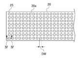
- FIG. 2 is a plan view showing a part of the substrate 20 used as a master when the nozzle plate 10 is formed by electric casting.
- the substrate 20 has a conductive surface 20a.
- a metal layer to be a nozzle plate 10 grows on the conductive surface 20a of the substrate 20. Since the nozzle plate 10 is provided with the nozzle 12, a circular mask 25 is formed on the substrate 20 at a position corresponding to the nozzle forming position where the nozzle 12 is formed on the conductive surface 20a.
- the mask 25 is made of a non-conductive material. Therefore, the metal does not grow in the portion of the mask 25 and becomes an opening, and the nozzle 12 is formed.
- 130 ⁇ 8 rows of masks 25 are formed in a region of 100 mm ⁇ 40 mm of the substrate 20 corresponding to the arrangement pitch and number of nozzles 12 of the nozzle plate 10 described above.
- the diameter DM of the mask 25 is larger than the diameter D of the nozzle 12, for example, 150 ⁇ m to 200 ⁇ m.
- the thickness of the mask 25 is, for example, 2 ⁇ m.
- the mask 25 since the mask 25 is formed on the flat substrate 20, the mask 25 is convex with respect to the conductive surface 20a of the substrate 20.
- FIG. 3 is a plan view showing the entire substrate 20. As shown in FIG. 3, the substrate 20 is, for example, a disk-shaped substrate having a diameter of 200 mm.
- the substrate 20 includes 130 ⁇ 8 rows of masks 25 shown in FIG. 2 in the nozzle plate forming regions A, B, and C having a size of 100 mm ⁇ 40 mm.
- the nozzle plate forming regions A, B, and C are arranged in a three-fold rotational symmetry with the normal line passing through the center 20c of the substrate 20 as the rotation axis. That is, in the substrate 20, the three nozzle plate forming regions A, B, and C are arranged at intervals of 120 ° with the normal as the rotation axis.
- the substrate 20 is provided with a metal film 22 on a glass wafer 21.
- the surface of the metal film 22 is the conductive surface 20a of the substrate 20.
- a non-conductive mask 25 is formed on a part of the conductive surface 20a (see FIG. 4).
- FIG. 4 is a diagram showing a manufacturing process of the nozzle plate 10.
- FIG. 4 shows a partial cross section including only one mask 25 of the substrate 20 shown in FIG.
- the preparation step S0 a substrate 20 having a non-conductive mask 25 formed on a part of the conductive surface 20a is prepared.
- the electroforming step S1 in a state where the substrate 20 is immersed in the electrolytic solution, the metal layer 11 is grown on the conductive surface 20a by the metal precipitated from the electrolytic solution.
- the metal layer 11 grows on the conductive surface 20a, while no metal is deposited on the surface of the non-conductive mask 25, and the metal layer 11 does not grow.
- the metal layer 11 gradually grows on the conductive surface 20a. After that, when the thickness of the grown metal layer 11 exceeds the thickness of the mask 25, the metal layer 11 covers the edge of the mask 25 from the surface of the previously grown metal layer 11 to the non-conductive mask 25 side. grow up. As the metal layer 11 grows from the edge of the mask 25 toward the center, an opening is formed in the metal layer 11 with the substantially center position of the mask 25 as the center of the opening. This opening becomes the nozzle 12.
- the metal layer 11 grows toward the center of the mask 25, so that the opening diameter of the nozzle 12 also gradually decreases.
- the diameter of the mask 25 is determined so that the nozzle 12 has a desired opening diameter when the metal layer 11 is grown to a desired thickness.
- the growth of the metal layer 11 proceeds as it approaches the conductive surface 20a. Therefore, as shown in FIG. 4, the opening diameter of the nozzle 12 is smaller as it is closer to the conductive surface 20a and larger as it is farther from the conductive surface 20a, and the cross section of the metal layer 11 constituting the inner wall surface of the nozzle 12 is formed. It becomes an arc shape.
- the opening diameter of the nozzle 12 closer to the conductive surface 20a is set. Then, the diameter of the mask 25 is determined so that the opening diameter of the reference nozzle 12 becomes the target opening diameter.
- the thickness t of the metal layer 11 is, for example, about 50 ⁇ m.
- the metal layer 11 is peeled from the substrate 20 (peeling step S2). At this time, the mask 25 is peeled off from the substrate 20 together with the metal layer 11.
- the mask 25 is removed (mask removal step S3). Thereby, the nozzle plate 10 can be obtained.
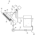
- the electroforming tank 32 stores the electrolytic solution 34.
- An anode 39 is arranged on a part of the inner wall surface of the electroplating tank 32.
- the substrate 20 is immersed in the electrolytic solution 34 of the electroforming tank 32.
- the substrate 20 is arranged so that the conductive surface 20a faces the anode 39.
- the anode 39 is configured to contain an electroplated metal such as nickel pellets and has a size capable of facing the entire region of the conductive surface 20a on the substrate 20. Electroplating is performed on the substrate 20 with the conductive surface 20a of the substrate 20 and the anode 39 facing each other.
- a part of the side wall of the electric casting tank 32 is inclined.
- the inclination direction of the side wall is a direction in which the upper opening is wider than the bottom surface of the electric casting tank 32 due to the inclination of the side wall, and the inclination angle of the side wall is, for example, about 40 ° to about 50 ° with respect to the horizontal direction. ..
- the anode 39 is arranged along the inner wall surface of the inclined side wall in a posture inclined with respect to the horizontal direction.
- the board holding mechanism 35 includes a holding portion 36, a rotating shaft 37, and a rotating device 38.
- the holding portion 36 holds the substrate 20 from the opposite surface side of the conductive surface 20a of the substrate 20.
- the rotating shaft 37 is attached to the back surface of the holding portion 36 and extends in the normal direction of the back surface of the holding portion 36.
- the rotating device 38 rotates the holding portion 36 via the rotating shaft 37.
- the holding portion 36 holds the substrate 20 in the electroplating tank 32 so that the conductive surface 20a of the substrate 20 faces the anode 39. That is, the substrate 20 is arranged with the conductive surface 20a in a vertical downward posture.
- the vertical downward posture means a posture in which the inclination angle of the conductive surface 20a with respect to the horizontal direction is 0 ° or more and less than 90 °.
- the tilt angle is larger than 0 °, and the conductive surface 20a is arranged in a posture tilted from the horizontal direction.
- the substrate 20 is held by the holding portion 36 so that the center coincides with the rotation axis 37.
- the rotating device 38 is driven, the substrate 20 rotates integrally with the holding portion 36 via the rotating shaft 37, with the center coincident with the rotating shaft 37 as the rotation center.
- the substrate 20 is set in the holding portion 36 outside the electric casting tank 32, and is immersed in the electric casting tank 32 in a held state by the holding portion 36. Then, electric casting is performed while rotating the substrate 20 about an axis extending in the normal direction from the center position in the plane of the conductive surface 20a.
- the conductive surface 20a of the substrate 20 is used as a cathode, and the conductive surface 20a serving as a cathode and the anode 39 containing the electroplated metal are energized.
- the electroplated metal of the anode 39 is electrolyzed and dissolved in the electrolytic solution 34 as electric ions.
- the metal deposited from the electrolytic solution 34 is electrodeposited on the conductive surface 20a serving as a cathode to form the metal layer 11.
- the circulation mechanism 40 includes a storage tank 41, a discharge pipe 42, a valve 43, a pump 44, a filter 46, a supply pipe 47, and a nozzle 48.
- the circulation mechanism 40 circulates the electrolytic solution 34 stored in the electroformed tank 32 between the electroformed tank 32 and the storage tank 41 arranged outside the electroformed tank 32. This circulation causes the electrolytic solution 34 to flow between the conductive surface 20a and the anode 39.
- the discharge pipe 42 and the supply pipe 47 form a circulation path for the electrolytic solution 34 between the electroformed tank 32 and the storage tank 41.
- the discharge pipe 42 constitutes a return pipe for discharging the electrolytic solution 34 in the electroformed tank 32 and returning the discharged electrolytic solution 34 to the storage tank 41 in the circulation path.
- the supply pipe 47 constitutes a supply pipe for supplying the electrolytic solution 34 from the storage tank 41 to the electroformed tank 32 in the circulation path.
- One end of the discharge pipe 42 is arranged in the electric casting tank 32, and the other end is connected to the storage tank 41.
- the discharge pipe 42 is returned to the electrolytic solution 34 storage tank 41 that exceeds a predetermined amount preset in the electroformed tank 32. Therefore, one end of the discharge pipe 42 is arranged at substantially the same height as the liquid surface of the specified amount of the electrolytic solution 34 with the opening facing upward. As a result, the electrolytic solution 34 exceeding the specified amount in the electroformed tank 32 flows into the discharge pipe 42 and is returned to the storage tank 41 through the discharge pipe 42.
- One end of the supply pipe 47 is also arranged in the electric casting tank 32, and the other end is connected to the storage tank 41.
- a nozzle 48 for injecting the electrolytic solution 34 into the electroforming tank 32 is connected to one end of the supply pipe 47.
- the other end of the supply pipe 47 is connected to the lower part of the storage tank 41.
- a valve 43, a pump 44, and a filter 46 are arranged in order from the storage tank 41 side, which is the upstream side in the supply direction of the electrolytic solution 34, on the supply pipe line composed of the supply pipe 47.
- the valve 43 opens and closes the supply path. When the supply path is opened by the valve 43 while the pump 44 is driven, the supply of the electrolytic solution 34 from the storage tank 41 to the electroformed tank 32 is started.
- the filter 46 filters the electrolytic solution 34.
- the electrolytic solution 34 that has passed through the filter 46 is supplied into the electroforming tank 32 through the supply pipe 47.
- the nozzle 48 injects the electrolytic solution 34 toward the conductive surface 20a of the substrate 20 and the anode 39.
- the electrolytic solution 34 is circulated between the electroforming tank 32 and the storage tank 41 by using the circulation mechanism 40. Then, in the electroplating tank 32, the electrolytic solution 34 is sprayed between the conductive surface 20a and the anode 39 by the nozzle 48, so that the fluid of the electrolytic solution 34 is directed toward the conductive surface 20a having the mask 25. The electrolytic solution 34 is made to flow in the direction in which the pressure is applied. The electroforming step S1 is carried out while flowing the electrolytic solution 34 in this way.
- Electroplating is performed on the conductive surface 20a of the substrate as described above.
- a substrate having a movement start angle of 20 ° or less for bubbles adhering to the surface of the mask 25 is used as the substrate 20 on which the non-conductive mask 25 is formed.
- the movement start angle is one of the indexes indicating the surface characteristics of the mask 25, and is defined here as follows.
- the movement start angle is the reference posture when the surface of the mask 25 is vertically downward and horizontal with the substrate 20 immersed in water, and the surface of the mask 25 is tilted from the reference posture. It is an inclination angle with respect to the reference posture of the surface of the mask when 3 ⁇ L (microliter) of air bubbles adhering to the surface of the mask 25 starts to move along the surface of the mask 25 by buoyancy.
- the substrate 20 Since the surface of the mask 25 and the conductive surface 20a of the substrate 20 on which the mask 25 is formed are parallel to each other, the substrate 20 is arranged so that the conductive surface 20a faces vertically downward and is in a horizontal posture. If this is the case, the above standard posture will be applied.
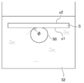
- the base material S which is a parallel flat plate having two main surfaces s1 and s2 parallel to each other, is placed in water so that one main surface s1 faces vertically downward and is horizontal. do.
- the fixing table 54 for fixing the base material S is immersed in water, and the fixing table 54 is installed so that the fixing surface 54a of the fixing table 54 is horizontal in water.
- the other main surface s2 of the base material S comes into contact with the fixing surface 54a of the fixing base 54.
- the base material S is arranged in the reference posture.
- the main surfaces s1 and s2 of the base material S are horizontal planes.
- a 3 ⁇ L bubble 50 is brought into contact with the main surface s1 of the base material S.
- a dispensing nozzle (not shown) is arranged below the main surface s1 of the base material S, and 3 ⁇ L of air is discharged toward the base material S. As a result, 3 ⁇ L of bubbles 50 are generated, and the generated bubbles 50 are brought into contact with the main surface s1 of the base material S.
- the base material S is gradually tilted together with the fixing table 54 and the fixing surface 54a from the reference posture shown in the upper figure of FIG.
- the angle formed by the fixed surface 54a when the bubble 50 starts moving along the main surface s1 of the base material S is measured. Since the main surface s1 of the base material S is parallel to the fixed surface 54a, the measured angle of the fixed surface 54a is the angle of the main surface s1 of the base material S, and the bubble 50 starts to move along the main surface s1. Corresponds to the movement start angle.
- the camera of the contact angle measuring device a state in which the base material S is gradually tilted together with the fixing base 54 is photographed from the horizontal direction, and the bubble 50 moves along the main surface s1 of the base material S.
- the angle formed by the fixed surface 54a in the horizontal direction is obtained from the image at the start by image analysis.
- the angle formed by the fixed surface 54a in the horizontal direction when the bubble 50 starts moving along the main surface s1 is measured, for example, at least three times, and the average value is taken as the movement start angle ⁇ with respect to the base material of the bubble.
- the water used for the measurement is distilled water, and the bubbles are air. If the surface of the base material S is replaced with the mask 25, the movement start angle ⁇ of the bubbles with respect to the surface of the mask 25 can be obtained in the same manner.
- the movement start angle ⁇ at which bubbles move from the surface of the mask 25 is one of the indexes indicating the surface characteristics of the mask 25, and is a guideline for measuring the ease with which the bubbles 50 stay on the surface of the mask 25.
- the movement start angle ⁇ of the 3 ⁇ L bubble is 20 ° or less, the bubble 50 has weak adhesion to the surface of the mask 25, so that the bubble 50 easily moves.
- the 3 ⁇ L bubble 50 corresponds to a spherical bubble 50 having a diameter of 4.6 mm. As the size of the bubble 50 becomes smaller, the buoyancy becomes smaller, so that the bubble 50 tends to be difficult to move. According to the study of the present inventor, even a minute bubble 50 having a diameter of several tens of ⁇ m or less moves to the surface of the mask 25 in which the movement start angle ⁇ of the 3 ⁇ L bubble 50 is 20 ° or less. It is easy to do so, and it is presumed that it has the effect of suppressing the adhesion of minute bubbles 50 to the surface of the mask 25.
- the movement start angle ⁇ in water is specified here, there is a correlation between the movement start angle ⁇ of the bubbles 50 in water and the movement start angle ⁇ of the bubbles 50 in the electrolytic solution during electroforming. That is, if the movement start angle ⁇ in water is large, the movement start angle ⁇ in the electrolytic solution is also large, and if the movement start angle ⁇ in water is large, the movement start angle ⁇ in the electrolytic solution is also large. According to the study of the present inventor, if the movement start angle ⁇ of the 3 ⁇ L bubble 50 on the surface of the mask 25 in water is 20 ° or less, the surface of the same mask 25 in the electrolytic solution during electroforming is used. It is presumed that the retention of the bubbles 50 can be suppressed and the effect of suppressing the adhesion of minute bubbles 50 having a diameter of several tens of ⁇ m or less can be suppressed.
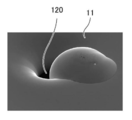
- FIGS. 7 to 10 show electron beam microscope images showing a state of molding failure of the nozzle 120 when a nozzle plate having a nozzle 120 for an inkjet printer is manufactured by electric casting by a conventional method.
- FIG. 7 is an image of the nozzle 120 observed from the front on the growth surface side
- FIG. 8 is an image of the nozzle 120 shown in FIG. 7 observed from an oblique direction.
- the nozzle 120 should have a circular opening shape, but the nozzle 120 having a molding defect has a crescent shape as shown in FIGS. 7 and 8.
- the portion that looks black is the nozzle 120.
- FIG. 9 is an image of the nozzle 120 shown in FIGS. 7 and 8 observed from the opposite surface side. In FIG. 9, it is more clearly shown that the opening shape of the nozzle 120 is crescent-shaped. Further, in FIG. 9, the region in the white frame defined by the circular white frame surrounding the crescent-shaped nozzle 120 is a region corresponding to the shape of the circular mask 25, and is a region of the mask 25 rather than the surrounding surface. The surface is recessed by the thickness.
- FIG. 10 is an enlarged image of the hole 121.
- the hole 121 is formed by a cavity formed inside the metal layer 11. That is, as shown in FIGS. 7 and 8, the abnormally bulging portion observed on the growth surface side of the metal layer 11 is considered to be due to the formation of a cavity inside. Then, it is presumed that the opening portion of this cavity becomes the hole 121 shown in FIGS. 9 and 10.
- the cause of the cavities in the metal layer 11 is considered to be the bubbles 50 adhering to the edge of the mask 25. That is, when electroforming is performed with the bubbles 50 attached, the metal layer 11 grows by entraining the bubbles 50, and as a result, a cavity is formed in the metal layer 11, and the cavity causes an abnormal bulge of the metal layer 11. it is conceivable that.
- the reference posture is such that the surface of the mask 25 is vertically downward and horizontal with the substrate 20 immersed in water.
- the surface of the mask 25 is tilted, the surface of the mask 25 is tilted with respect to the reference posture when the 3 ⁇ L air bubbles adhering to the surface of the mask 25 in the reference posture start moving along the surface of the mask 25 by buoyancy.
- the nozzle 12 (an example of the opening of the metal molded product) of the nozzle plate 10 which is an example of the metal molded product is used. Molding defects can be reduced. In particular, it is easy to remove minute bubbles having a diameter of several tens of ⁇ m or less. Therefore, in the case of manufacturing a metal molded product having a nozzle 12 (an example of an opening of the metal molded product) having a nozzle size of 100 ⁇ m or less, such as the nozzle plate 10, the effect of suppressing the molding defect of the opening is high.
- the movement start angles ⁇ of the surface of the mask 25 and the conductive surface 20a are compared under the same conditions, it is preferable to use the substrate 20 having a smaller movement start angle ⁇ on the surface of the mask 25.
- the conductive surface 20a from the surface of the mask 25 is compared with the case where the movement start angle is the same between the surface of the mask 25 and the conductive surface 20a. Since the bubbles 50 are easily moved toward the surface, it is possible to more reliably reduce the molding defects of the openings.
- the conductive surface 20a is a flat surface
- the mask 25 is formed on the flat conductive surface 20a.
- the mask 25 is arranged so as to be convex with respect to the conductive surface 20a. It is a configuration that has been done.
- the mask 25 may be formed at a position one step lower than the conductive surface 20a of the substrate 20, and the portion where the mask 25 is formed may be a recess.
- the heights of the conductive surface 20a and the surface of the mask 25 may be the same, and both may be on the same surface.
- the method for manufacturing a metal molded product according to the second embodiment also includes an electroplating step using a substrate 20 in which a non-conductive mask 25 is formed on a part of a conductive surface 20a. ..
- the electroforming process in a state where the substrate 20 is immersed in the electrolytic solution 34, the metal layer 11 is grown on the conductive surface 20a by the metal deposited from the electrolytic solution 34, and an opening is opened at a position corresponding to the mask 25.
- a manufacturing method for manufacturing the nozzle plate 10 as a metal molded product will be described.
- the overall flow of the manufacturing process shown in FIG. 4 is basically the same as that of the first embodiment described above. In the following, only the differences will be described, and detailed explanations will be omitted for the same parts.
- the substrate 20 on which the non-conductive mask 25 is formed the substrate 20 satisfying the following conditions is used as the condition regarding the contact angle of the bubbles 50 with respect to the mask 25.
- the contact angle of the bubble 50 is defined as follows. That is, with the substrate 20 immersed in water, the reference posture is that the surface of the mask 25 is vertically downward and horizontal, and the 3 ⁇ L air bubbles 50 adhering to the surface of the mask 25 in the reference posture are masked from the reference posture.
- the contact angle on the movement direction side where the bubble 50 moves due to buoyancy is set as the first contact angle ⁇ 1, and the contact on the opposite side of the movement direction.
- the angle is the second contact angle ⁇ 2.
- a method for measuring the contact angle ⁇ of the bubble 50 will be described.
- a base material S which is a parallel flat plate having two main surfaces s1 and s2 parallel to each other, is placed in a water tank in which water 52 is stored, and one main surface s1 faces vertically downward and. Place it in water so that it is horizontal.
- the fixing table 54 (not shown in FIG. 11) shown in FIG. 6 is used and arranged so that the other main surface s2 of the base material S comes into contact with the fixing surface 54a.
- the base material S is arranged in the reference posture.
- the main surfaces s1 and s2 of the base material S are horizontal planes.
- a 3 ⁇ L bubble 50 is brought into contact with the main surface s1 of the base material S.
- the contact angle ⁇ of the bubble 50 is the tangent line of the bubble 50 at the end where the bubble 50 is in contact with the base material S and the base material S when the bubble 50 in contact with the base material S is observed from the horizontal direction.
- the angle to make Specifically, using the camera of the contact angle measuring device, the air bubbles 50 in contact with the horizontally arranged base material S and the surface of the base material S are photographed from the horizontal direction, and the tangent line of the air bubbles 50 and the base material S are aligned with each other.
- the angle to be formed is obtained by image analysis. The measurement is performed, for example, at least three times, and the average value thereof is defined as the contact angle ⁇ . If the surface of the base material S is replaced with the mask 25, the contact angle ⁇ of the bubbles with respect to the surface of the mask 25 can be obtained in the same manner.
- the first contact angle ⁇ 1 is the contact angle on the moving direction side in which the bubble 50 moves in the above-mentioned movement start angle ⁇ (see FIG. 6), and this contact angle is also the forward contact angle. Called.
- the second contact angle ⁇ 2 is a contact angle on the side opposite to the moving direction in which the bubble moves immediately before the moving start angle, and this contact angle is also referred to as a reverse contact angle. Similar to the case of the movement start angle ⁇ shown in FIG. 6, 3 ⁇ L of bubbles 50 are attached to the surface of the base material S, and the base material S is fixed from the reference posture to the fixing base 54 (not shown in FIG.
- the fixed surface 54a is tilted in a direction in which the angle formed by the horizontal surface increases.
- the contact angle of the bubble 50 is measured when the inclination angle of the main surface s1 of the base material S with respect to the horizontal direction becomes the movement start angle ⁇ , that is, immediately before the bubble 50 starts to move.
- a state in which the base material S is gradually tilted together with the fixing base 54 is photographed from the horizontal direction, and the movement of the bubbles in the image immediately before the bubble 50 leaves the base material S.
- the angle between the tangent line and the base material S at the end on the direction side and the angle between the tangent line and the base material S at the end opposite to the moving direction of the bubble 50 are obtained by image analysis.
- the measurement is performed at least three times for each angle, and the average value thereof is set to the first contact angle ⁇ 1 and the second contact angle ⁇ 2, respectively.
- the angle difference ⁇ between the first contact angle ⁇ 1 and the second contact angle ⁇ 2 thus obtained is obtained.
- the angle difference ⁇ between the first contact angle ⁇ 1 and the second contact angle ⁇ 2 at the movement start angle at which the bubble 50 moves from the surface of the mask 25 is one of the indexes showing the surface characteristics of the mask 25, and is to the surface of the mask 25. This is a guideline for measuring the easiness of retention of the bubbles 50.
- the angle difference ⁇ between the first contact angle ⁇ 1 and the second contact angle ⁇ 2 indicates the asymmetry between the moving direction side and the opposite side of the moving direction of the bubble 50.
- the bubble 50 When the angle difference ⁇ is 30 ° or less, the bubble 50 has weak adhesion to the surface of the mask 25, so that the bubble 50 can easily move. As the size of the bubble 50 becomes smaller, the buoyancy becomes smaller, so that the bubble 50 tends to be difficult to move. According to the study of the present inventor, for a surface where the angle difference of 3 ⁇ L bubbles is 30 ° or less, even minute bubbles 50 having a diameter of several tens of ⁇ m or less can easily move to the mask surface. It has the effect of suppressing the adhesion of minute bubbles.
- the angle difference of the bubble 50 immediately before the bubble 50 starts to move from the surface of the mask 25 in water is specified here, there is a correlation between the angle difference in water and the angle difference in the electrolytic solution at the time of electroforming. be. That is, if the angle difference in water is large, the angle difference in the electrolytic solution is large, and if the angle difference in water is large, the angle difference in the electrolytic solution is also large. According to the study of the present inventor, if the angle difference immediately before the start of movement of 3 ⁇ L bubbles on the surface of the mask 25 in water is 30 ° or less, the same mask 25 in the electrolytic solution at the time of electroforming is used. It is possible to suppress the retention of bubbles on the surface, and it has the effect of suppressing the adhesion of minute bubbles having a diameter of several tens of ⁇ m or less.
- the reference posture is such that the surface of the mask 25 is vertically downward and horizontal with the substrate 20 immersed in water.
- the 3 ⁇ L bubble 50 adhering to the surface of the mask 25 is the difference between the first contact angle ⁇ 1 and the second contact angle ⁇ 2 of the bubble 50 immediately before the start of movement by inclining the surface of the mask 25 from the reference posture.
- a substrate 20 having an angle difference ⁇ of 30 ° or less is used.
- the substrate 20 having a smaller angle difference ⁇ on the surface of the mask 25 it is preferable to use the substrate 20 having a smaller angle difference ⁇ on the surface of the mask 25.
- the angle difference of the surface of the mask 25 By making the angle difference of the surface of the mask 25 smaller than that of the conductive surface 20a, the surface of the mask 25 becomes the conductive surface 20a as compared with the case where the angle difference ⁇ is the same between the surface of the mask 25 and the conductive surface 20a. Since the bubbles 50 are easily moved toward the air bubbles 50, it is possible to more reliably reduce the molding defects of the openings.
- the first embodiment is an embodiment in which the substrate 20 uses a substrate 20 in which the movement start angle ⁇ of the bubbles 50 on the surface of the mask 25 is 20 ° or less as the surface characteristic of the mask 25.
- the angle difference ⁇ which is the difference between the first contact angle ⁇ 1 and the second contact angle ⁇ 2 of the bubbles on the surface of the mask 25, is 30 ° or less. It is an embodiment using a certain substrate 20. Further, as the substrate 20 on which the non-conductive mask 25 is formed, it is preferable to use the substrate 20 having the surface characteristics of each of the masks 25 of the first embodiment and the second embodiment.
- the movement of 3 ⁇ L bubbles adhering to the surface of the mask 25 in the reference posture is due to the buoyancy of the contact angle of the bubbles immediately before the movement starts by inclining the surface of the mask 25 from the reference posture.
- the angle difference which is the difference between the first contact angle and the second contact angle, is 30 °. It is preferable to use the following substrate. By using such a substrate 20, the adhesion of air bubbles on the mask 25 can be suppressed more effectively, so that the molding defect of the nozzle 12 can be suppressed more effectively.
- the contact angle ⁇ of the bubbles 50 adhering to the mask 25 in the reference posture is 130 ° or more. It is more preferable that the contact angle ⁇ of the bubbles adhering to the mask 25 in the reference posture is 130 ° or more.
- the contact angle ⁇ of the bubble 50 is 130 ° or more, the adhesive force of the bubble 50 to the surface of the mask 25 is weak, so that the bubble 50 can easily move.
- the contact angle ⁇ of the bubble 50 is 130 ° or more, even a minute bubble 50 having a diameter of several tens of ⁇ m or less can easily move, and the mask 25 can be used. The effect of suppressing the adhesion of minute bubbles 50 to the surface is further improved.
- the contact angle of the bubbles 50 in water is specified here, there is a correlation between the contact angle of the bubbles 50 in water and the contact angle of the bubbles 50 in the electrolytic solution during electroforming. That is, if the contact angle of the bubbles in water is large, the contact angle of the bubbles in the electrolytic solution is also large, and if the contact angle of the bubbles in water is large, the contact angle of the bubbles in the electrolytic solution is also large. According to the study of the present inventor, if the contact angle of the 3 ⁇ L bubbles 50 adhering to the mask 25 in the reference posture is 130 ° or more, the bubbles 50 on the surface of the same mask 25 in the electrolytic solution during electroforming. It is possible to suppress the retention of bubbles, and it has the effect of suppressing the adhesion of minute bubbles having a diameter of several tens of ⁇ m or less.
- the molding defect of the nozzle 12 can be suppressed.
- the substrate 20 on which the non-conductive mask 25 is formed the substrate 20 in which the contact angle ⁇ of the bubbles 50 adhering to the mask 25 in the reference posture is 130 ° or more is used.
- the bubbles 50 can be easily removed from the surface of the mask, it is possible to further reduce the molding defects of the openings of the metal molded product.
- it is easy to remove minute bubbles 50 having a diameter of several tens of ⁇ m or less the effect of suppressing the molding defect of the opening is further enhanced in a metal molded product having an opening of 100 ⁇ m or less such as a nozzle plate 10.
- the contact angle of the bubbles 50 with respect to the surface of the mask 25 becomes large in water. Further, when the surface of the mask 25 is hydrophobic, the contact angle of the bubbles 50 with respect to the mask surface becomes small in water. That is, the more hydrophilic the surface of the mask 25 is, the larger the contact angle of the bubbles 50 is, and the higher the effect of suppressing the adhesion of the bubbles 50 is.
- the contact angle ⁇ is larger on the surface of the mask 25. It is preferable to use the substrate 20.
- the contact angle ⁇ of the bubbles 50 on the surface of the mask 25 is smaller than that of the conductive surface 20a, the contact angle ⁇ is the same on the surface of the mask 25 and the conductive surface 20a, and the contact angle ⁇ is the same from the surface of the mask 25. Since the bubbles 50 are easily moved toward the surface 20a, it is possible to more reliably reduce the molding defects of the openings in the metal molded product.
- the substrate 20 is arranged in an electrolytic solution in which the conductive surface 20a is oriented downward in the vertical direction, whereas the substrate 20 has the conductive surface 20a in the vertical direction. It may be arranged in an upward position.
- the conductive surface 20a is upward in the vertical direction, the bubbles 50 cannot be pressed by the substrate 20, so that the bubbles 50 can be easily moved by buoyancy as compared with the case where the conductive surface 20a is downward in the vertical direction. Therefore, bubbles on the mask surface can be reduced more reliably.
- the pressing force applied by the substrate 20 to the bubbles 50 causes the conductive surface 20a to move as compared with the case where the conductive surface 20a is vertically upward. It gets hot.
- the substrate 20 described in the above embodiment even when the conductive surface 20a is arranged downward in the vertical direction, it is possible to suppress the adhesion of bubbles to the surface of the mask 25. As a result, it is possible to reduce molding defects of openings in the metal molded product. Further, by setting the conductive surface 20a in a vertical downward posture, foreign matter in the electrolytic solution falling from above in the vertical direction adheres to the conductive surface as compared with the vertical upward posture. It can be suppressed.
- the inclination angle of the conductive surface having the mask 25 with respect to the horizontal direction is 60 ° or less. Adhesion of conductive surface foreign matter can be suppressed more reliably.
- the substrate 20 is rotated about an axis extending in the normal direction from the center position in the plane of the electric surface by using the electroplating apparatus shown in FIG.
- electroplating may be performed while holding the substrate 20 in a fixed position without rotating the substrate 20.
- the electrocasting conditions at each position of the substrate 20 are not biased, and the metal layer is formed under uniform electrocasting conditions over the entire area. It becomes possible.
- FIG. 3 when a plurality of nozzle plate forming regions A, B, and C are provided in one substrate 20, individual differences between metal molded products are suppressed, and equivalent metal molding is performed. It becomes possible to manufacture things.
- the electroforming step of the metal molded product manufacturing method of the above embodiment is carried out while flowing the electrolytic solution in the direction in which the fluid pressure of the electrolytic solution is applied toward the conductive surface 20a of the substrate 20, but the electrolytic solution 34 is carried out.
- the electroforming process may be performed without flowing.
- by carrying out the electroplating step while flowing the electrolytic solution in the direction in which the fluid pressure of the electrolytic solution is applied toward the conductive surface 20a adhesion of foreign matter to the surface of the mask 25 and the conductive surface 20a is suppressed. can do. Further, it is possible to obtain the effect of removing the bubbles 50 remaining on the surface of the mask 25.
- a metal film 22 may be provided on one surface of the glass wafer 21. It is obtained by forming a metal film 22 such as nickel or copper on a glass wafer 21 by sputtering, vacuum deposition or the like. Further, as the substrate 20 having the conductive surface 20a, a metal substrate may be used. If it is a metal substrate, it is not necessary to separately form a metal film by sputtering or the like.
- the non-conductive material which is the material of the non-conductive mask 25 may be a metal oxide or a photosensitive resin.
- a thin-film deposition mask having an opening having a desired mask shape is placed on the substrate 20 so as to face the conductive surface 20a of the substrate 20, and the mask 25 is vacuum-deposited.
- the metal oxide include silicon oxide.
- the mask 25 remains on the substrate side when the metal layer is peeled off in the peeling step described in the method for producing a metal molded product of the above embodiment. Therefore, it is possible to repeatedly use the substrate on which the non-conductive mask 25 is formed on a part of the conductive surface a plurality of times.
- the non-conductive mask 25 is preferably hydrophilized before the electroplating process.
- the movement which is the inclination angle with respect to the reference posture of the surface of the mask 25 when the 3 ⁇ L bubbles 50 adhering to the surface of the mask 25 start moving along the surface of the mask 25 by buoyancy.
- the starting angle ⁇ can be 20 ° or less.
- it is the difference between the first contact angle ⁇ 1 and the second contact angle ⁇ 2 of the bubble immediately before the bubble of 3 ⁇ L starts to move by inclining the surface of the mask 25 from the reference posture by performing the hydrophilization treatment.
- the angle difference ⁇ can be 30 ° or less.
- the movement start angle ⁇ which is the inclination angle of the surface of the mask 25 with respect to the reference posture when the 3 ⁇ L bubbles 50 adhering to the surface of the mask 25 start moving along the surface of the mask 25 by buoyancy, is 20.
- the angle difference ⁇ which is the difference from ⁇ 2, can be set to 30 ° or less.
- the method of hydrophilization treatment is not particularly limited, but plasma treatment or ultraviolet ozone treatment is preferable.
- the hydrophilic treatment can be uniformly and uniformly performed over the entire area of the substrate 20.
- the metal molded product manufacturing method of each of the above embodiments may include a mask forming step of forming a mask on the conductive surface 20a.
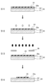
- An example mask forming step includes a photosensitive resin coating step, an exposure step, and a developing step, and further, a hydrophilic treatment of the photosensitive resin is performed at any stage after the coating step. In particular, it is preferable to hydrophilize the photosensitive resin after the coating step and before the developing step.
- the mask preparation step in the above embodiment includes a mask forming step.
- a specific example of the mask forming step will be described with reference to FIG.
- the coating step S11, the hydrophilic treatment S12, the exposure step S13, and the developing step S14 are carried out in this order. That is, the hydrophilic treatment is performed before the exposure step.
- the photosensitive resin film 24 is coated and formed on the metal film 22 on the glass wafer 21, that is, on the conductive surface 20a of the substrate 20.
- the hydrophilic treatment S12 the entire surface of the photosensitive resin film 24 is subjected to a hydrophilic treatment.
- a hydrophilic treatment plasma treatment or ultraviolet ozone treatment is performed.
- the mask 26 for pattern formation is arranged on the photosensitive resin film 24, and the photosensitive resin film 24 is exposed to the pattern.
- the exposed photosensitive resin film 24 is developed to obtain a substrate 20 having the mask 25 on the conductive surface 20a.
- the photosensitive resin film 24 is hydrophilized in this way, when the surface of the mask 25 is tilted from the reference posture while the substrate 20 is immersed in water, the mask 25 is in the reference posture.
- the movement start angle ⁇ which is an inclination angle with respect to the reference posture of the surface of the mask 25 when the 3 ⁇ L air bubbles 50 adhering to the surface of the mask 25 start moving along the surface of the mask 25 by buoyancy, is 20 ° or less.
- the surface of the photosensitive resin film 24, that is, the mask 25 is hydrophilized, the surface of the mask 25 is oriented vertically downward and horizontally while the substrate 20 is immersed in water.
- the 3 ⁇ L bubbles 50 adhering to the surface of the mask 25 in the reference posture move by buoyancy with respect to the contact angle of the bubbles immediately before the movement starts by inclining the surface of the mask 25 from the reference posture.
- This is the difference between the first contact angle ⁇ 1 and the second contact angle ⁇ 2 when the contact angle on the moving direction side is the first contact angle ⁇ 1 and the contact angle on the opposite side to the moving direction is the second contact angle ⁇ 2.
- the angle difference ⁇ is 30 ° or less.
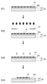
- the coating step S21, the exposure step S22, the hydrophilic treatment S23, and the developing step S24 are carried out in this order. That is, after the exposure step S22 and before the development step S24, the hydrophilic treatment is performed.
- the photosensitive resin film 24 is uniformly coated on the metal film 22 on the glass wafer 21, that is, on the conductive surface 20a of the substrate 20.
- the mask 26 for pattern formation is arranged on the photosensitive resin film 24, and the photosensitive resin film 24 is exposed to the pattern.
- the hydrophilic treatment S23 the entire surface of the photosensitive resin film 24 is subjected to a hydrophilic treatment.
- a hydrophilic treatment plasma treatment or ultraviolet ozone treatment is performed.
- the exposed photosensitive resin film 24 is developed to obtain a substrate 20 having the mask 25 on the conductive surface 20a.
- the reference posture is obtained when the surface of the mask 25 is tilted from the reference posture while the substrate 20 is immersed in water.
- the movement start angle which is the inclination angle of the surface of the mask 25 with respect to the reference posture when the 3 ⁇ L air bubbles 50 adhering to the surface of the mask 25 start moving along the surface of the mask 25 by buoyancy, is 20 ° or less. be.
- the surface of the photosensitive resin film 24, that is, the mask 25 is hydrophilized, the surface of the mask 25 is vertically downward and the horizontal posture is used as a reference while the substrate 20 is immersed in water.
- the 3 ⁇ L bubbles 50 adhering to the surface of the mask 25 in the reference posture move by buoyancy with respect to the contact angle of the bubbles 50 immediately before the movement starts by inclining the surface of the mask 25 from the reference posture.
- This is the difference between the first contact angle ⁇ 1 and the second contact angle ⁇ 2 when the contact angle on the moving direction side is the first contact angle ⁇ 1 and the contact angle on the opposite side to the moving direction is the second contact angle ⁇ 2.
- the angle difference ⁇ is 30 ° or less.
- the hydrophilization treatment is performed before the exposure step or after the exposure step and before the development step, but the hydrophilization treatment is performed before the exposure step, after the exposure step, before the development step, or after the development step. You may. Regardless of the stage of the hydrophilization treatment, the surface of the mask 25 is hydrophilized and the above effect can be obtained. However, by performing the hydrophilization treatment before the exposure step or after the exposure step and before the development step, it is possible to suppress a decrease in yield due to the phenomenon that the metal layer 11 is peeled off from the conductive surface during electroplating. ..
- the effect of the hydrophilization treatment will be described.
- a photosensitive resin film after coating that had not been exposed, developed and washed, a photosensitive resin film after development and cleaning that had been exposed, developed and washed, and a Ni spatter film were prepared. ..
- the Ni sputtered film is an example of a metal film constituting the conductive surface of the substrate.
- a low-pressure mercury lamp (emission main wavelength 254 nm, output 200 W) was used for ultraviolet ozone treatment, and irradiation was performed for 20 minutes.
- the water contact angle was measured using a contact angle meter DMo-501 manufactured by Kyowa Surface Science Co., Ltd., and a 10-point average value was taken. The results are shown in Table 1.
- the photosensitive resin was hydrophilized by applying ultraviolet ozone treatment, and the water contact angle was significantly reduced.
- the effect on the ultraviolet ozone treatment did not change significantly even after the development cleaning and before the development cleaning.
- the Ni sputtered film had no effect of hydrophilization by the ultraviolet ozone treatment, and the result was that the water contact angle was slightly increased. That is, as the hydrophilization treatment, almost the same hydrophilization effect was obtained even when the exposure and development treatments were not performed.
- FIG. 15 shows the results of measuring the contact angle ⁇ of 3 ⁇ L bubbles in water for each of the Ni spatter film, the photosensitive resin film, and the photosensitive resin film treated with ultraviolet ozone as a hydrophilization treatment.
- the contact angle was measured three times for each film.
- the range indicated by the bar in the figure is the range from the minimum value to the maximum value among the three measured values, and the dot indicates the average value of the three measured values. In the following, the average value of the three measured values is taken as the contact angle ⁇ of each film.
- the contact angle ⁇ of the bubbles with respect to the Ni sputtered film is 125 °
- the contact angle ⁇ of the bubbles with respect to the photosensitive resin film not subjected to the hydrophilization treatment is 115 °
- the contact angle ⁇ of the bubbles with respect to the photosensitive resin film treated with ultraviolet ozone. was 145 °.
- the contact angle ⁇ of the bubbles with respect to the photosensitive resin film which has not been hydrophilized is smaller than that of the Ni sputtered film.
- the contact angle ⁇ of the bubbles with respect to the photosensitive resin film subjected to the hydrophilization treatment is larger than the contact angle ⁇ of the bubbles with respect to the photosensitive resin film and the Ni spatter film which have not been hydrophilized. That is, the effect of increasing the contact angle ⁇ of the bubbles was obtained by the hydrophilization treatment.
- FIG. 16 shows the results of measuring the movement start angle ⁇ of bubbles for each of the Ni spatter film, the photosensitive resin film, and the photosensitive resin film treated with ultraviolet ozone as a hydrophilization treatment.
- the movement start angle was measured three times for each membrane.
- the range indicated by the bar in the figure is the range from the minimum value to the maximum value among the three measured values, and the dot indicates the average value of the three measured values. In the following, the average value of the three measured values is taken as the movement start angle ⁇ of each film.
- the movement start angle ⁇ of the Ni spatter film is 38 °
- the movement start angle ⁇ of the photosensitive resin film not subjected to the hydrophilization treatment is 48 °
- the movement start angle ⁇ of the photosensitive resin film treated with ultraviolet ozone treatment is almost 0. It was °.
- the movement start angle ⁇ of the photosensitive resin film not subjected to the hydrophilization treatment was larger than that of the Ni sputtered film, and the bubbles sometimes did not move even when tilted up to 60 °.
- the movement start angle ⁇ of the photosensitive resin subjected to the hydrophilization treatment was approximately 0 °. In the photosensitive resin subjected to the hydrophilization treatment, bubbles were moving even before the angle of the substrate was tilted, and the high effect of improving the mobility of the bubbles in the photosensitive resin film by the hydrophilization treatment was obtained.
- FIG. 17 is a diagram schematically showing the shape of bubbles at the time of measuring the angle difference for each film.
- FIG. 17A shows the shape of bubbles when measuring the angle difference for the Ni spatter film
- FIG. 17B shows the shape of the bubbles when measuring the angle difference for the photosensitive resin film which has not been hydrophilized
- FIG. 17C shows the photosensitizer which has been hydrophilized.
- the shape of the bubble when measuring the angle difference is shown for each of the sex resin films.
- the angle difference ⁇ was 44 ° for the photosensitive resin film that had not been hydrophilized, 36 ° for the Ni spatter film, and approximately 0 ° for the photosensitive resin film that had been hydrophilized.
- the angle difference ⁇ of the photosensitive resin film not subjected to the hydrophilization treatment is larger than that of the Ni sputtered film.
- the angle difference ⁇ of the photosensitive resin subjected to the hydrophilization treatment was approximately 0 °, which was smaller than that of the photosensitive resin film and the Ni spatter film not subjected to the hydrophilic treatment.
- the effect of improving the mobility of bubbles in the photosensitive resin film by performing the hydrophilization treatment is also shown from the angle difference ⁇ .
- Example 1 A nozzle plate was produced by the method for producing a metal molded product of Example 1.
- the manufacturing method according to Example 1 was as follows.
- a Ni film was sputter-deposited on a glass wafer to obtain a substrate having a conductive surface made of the Ni film. Then, a mask for forming a nozzle was formed on the surface of the Ni film of the substrate by the following mask forming step, and a substrate having three nozzle plate forming regions A, B, and C as shown in FIG. 3 was produced.
- the nozzle plate forming regions A, B, and C were 100 mm ⁇ 40 mm, and 130 masks ⁇ 8 rows each having a diameter of 150 ⁇ m and a mask thickness of 2 ⁇ m were arranged.
- a photosensitive resin film is applied and formed on the surface of the Ni film on the glass wafer (coating step), a mask for pattern formation is placed on the photosensitive resin film, and the photosensitive resin is exposed to the pattern (exposure step). , And developed (development process) to form a mask. Then, the mask and the surface of the Ni film were hydrophilized with oxygen plasma.
- the water contact angle on the mask surface was 8.4 °.
- the contact angle of the bubbles on the mask surface in water was 148 °, the movement start angle was 0 °, and the angle difference between the first contact angle and the second contact angle was 0 °.
- the glass wafer is placed in the electroforming tank.
- Ni electroforming was performed while rotating in (electroforming process) to grow a metal layer on the Ni film of the substrate (electroforming process).
- Electrocasting was performed until the thickness of the metal layer became approximately 50 ⁇ m and the opening diameter on the mask reached a desired value (design value 40 ⁇ m).
- the metal layer is peeled from the substrate (peeling step), and in the peeling step, the mask adhering to a part of the metal layer is removed (mask removal step) to prepare the nozzle plate of Example 1 composed of the metal layer. did.
- the water contact angle on the mask surface was 80.3 °.
- the contact angle of the bubbles on the mask surface in water was 110 °, the movement start angle was 38 °, and the angle difference between the first contact angle and the second contact angle was 40 °.
- Example 2 A nozzle plate was produced by the method for producing a metal molded product of Example 2.
- Example 2 In the manufacturing method of Example 2, in the manufacturing process of Example 1, the hydrophilization treatment was carried out in the mask forming step after the exposure step and before the developing step. Further, the nozzle plate of Example 2 was produced in the same manner as in Example 1 except that the design value of the nozzle diameter was 41 ⁇ m.
- the water contact angle on the mask surface of the substrate obtained in the mask forming step was 18 °.
- the contact angle of the bubbles on the mask surface in water was 145 °, the movement start angle was 2 °, and the angle difference between the first contact angle and the second contact angle was 5 °.
- the conditions of the mask surface of the substrate of this Example 3 were almost the same as those of Example 1.
- Nozzle diameters were measured for the nozzle plates obtained in each Example and Comparative Example.
- Example 1 and Comparative Example the nozzle plates 10A, 10B, and 10C obtained in the nozzle plate forming regions A, B, and C, respectively, and for Example 2, the nozzle plate 10A obtained in the nozzle plate forming region A. Nozzle diameter was measured for.
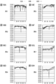
- FIG. 18 is a measurement result for Example 1
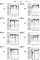
- FIG. 19 is a comparative example
- FIG. 20 is a measurement result for Example 2.
- 18A to 18H are measurement results for each of the rows 1 to 8 in the sub-scanning direction of the nozzle plates 10A, 10B, and 10C of the first embodiment.
- 19A to 19H are measurement results for each of the rows 1 to 8 in the sub-scanning direction of the nozzle plates 10A, 10B, and 10C of the comparative example.
- 20A to 20H are measurement results for each of the rows 1 to 8 in the sub-scanning direction of the nozzle plate 10A of the second embodiment.
- the vertical axis is the nozzle opening and the unit is mm.
- the horizontal axis is the nozzle position in the main scanning direction of the nozzle plate.
Landscapes
- Engineering & Computer Science (AREA)
- Manufacturing & Machinery (AREA)
- Chemical & Material Sciences (AREA)
- Chemical Kinetics & Catalysis (AREA)
- Electrochemistry (AREA)
- Materials Engineering (AREA)
- Metallurgy (AREA)
- Organic Chemistry (AREA)
- Particle Formation And Scattering Control In Inkjet Printers (AREA)
Abstract
導電性表面の一部に非導電性のマスクが形成された基板を用い、基板を電解液中に浸漬させた状態で、電解液中から析出する金属によって導電性表面で金属層を成長させ、かつ、マスクに対応する位置に開口を形成する電鋳工程を含み、電鋳工程を実行することにより開口を有する金属成形物を製造する金属成形物製造方法であって、基板を水中に浸漬した状態で、マスクの表面が鉛直方向下向きでかつ水平な姿勢を基準姿勢とし、基準姿勢からマスクの表面を傾斜させる場合において、基準姿勢でマスクの表面に付着している3μLの気泡が浮力によってマスクの表面に沿って移動を開始する際のマスクの表面の基準姿勢に対する傾斜角である移動開始角が20°以下である。
Description
本開示は、金属成形物製造方法に関する。
電鋳技術を用いて複数の開口を有する金属成形物を製造する金属成形物製造方法が知られている(例えば、特開2008-23792号公報参照)。特開2008-23792号公報に記載の金属成形物製造方法では、導電性表面の一部に非導電性のマスクが形成された基板を用い、基板を電解液中に浸漬させた状態で、電解液中から析出する金属によって導電性表面で金属層を成長させ、かつ、マスクに対応する位置に開口を形成する電鋳工程を含み、電鋳工程を実行することにより、開口を有する金属成形物を製造している。マスクは例えば感光性樹脂である。
特開2008-23792号公報では、金属成形物として、インクジェットプリンタの記録ヘッドに用いられるノズルプレートを製造している。ノズルは、インクを吐出することにより、印刷する画像の構成要素である画素に対応するドットを記録する。
ノズルプレートは、金属製の薄板に、インク吐出用のノズルとして機能する複数の開口が一次元又は二次元に配列されたものである。このように配列された複数の開口を形成するために、特開2008-23792号公報においては、導電性表面に一次元又は二次元に複数のマスクが配列された基板が用いられる。
特開2002-80995号公報には、電鋳技術を用いて回路基板に形成された溝及びスルーホールなどに金属配線を行う方法が記載されている。特開2002-80995号公報においては、電解液中において回路基板の表面に直径が100μm程度の気泡が付着すること、及び付着した気泡によって配線パターンの欠落又は配線膜厚の減少が生じることが記載されている。こうした課題の解決策として、特開2002-80995号公報においては、電解液中において回路基板を傾斜させた姿勢で配置することにより、回路基板の表面に付着した気泡を浮力によって表面から除去することが記載されている。
特開2008-23792号公報に記載のノズルプレートの複数の開口は、それぞれがインクを吐出するノズルとして機能するため、複数の開口の形状及びサイズに高い均一性が要求される場合がある。というのも、各ノズルからのインクの吐出量が不均一であると、記録ヘッドによって印刷する画像の画素に対応するドットの大きさが不均一となり、画質が低下する。画質を向上させるためには、各ノズルからのインクの吐出量を均一化する必要がある。そのためには、ノズルプレートにおいて各ノズルとして機能する開口には高い寸法精度が要求される。
近年の画質向上の要請から、画像の解像度は高くなる傾向があり、その場合、ドットの大きさを小さくする必要があるため、ノズルプレートの開口のサイズも数十μm程度に小さくする必要がある。直径が数十μm程度の開口を形成する場合、特開2008-23792号公報に記載の方法によりノズルプレートを製造する場合は、例えば、基板の導電性表面には直径が100μm程度のマスクが形成される。そして、導電性表面から成長する金属層をマスクの周縁の縁部に被さるように形成することにより、マスクの中央部分に数十μmの開口を形成する。このように開口のサイズが小さなノズルプレートを製造する場合において、特開2008-23792号公報に記載の方法を単純に実施するだけでは、複数の開口のサイズ及び形状が不均一になるという開口の成形不良が生じる場合があった。
本願の発明者は、分析の結果、直径が数十μm以下の気泡が非導電性のマスクに付着することが開口の成形不良の主要な原因であることを突き止めた。分析によれば、気泡に起因する開口の成形不良のメカニズムは次のように推定される。マスクに気泡が付着すると、マスクの縁部に覆い被さるように成長する金属層が気泡を巻き込みながら成長する。金属層が気泡を巻き込むと、気泡を内包した金属層が他の部分よりも大きく膨らんで形成される。このように、マスクの縁部において金属層が膨らんで形成されると、金属層がマスクの縁部から中央部分に向かって膨出する。マスクの中央に向かって金属層が膨出する分、開口のサイズが小径になる、あるいは、円形となるべき開口の形状が三日月状になり、これが開口の成形不良となる。
特開2002-80995号公報に記載されているように、電解液中において基板を傾斜させることにより、マスクの表面に付着した気泡を浮力によって基板から除去することが考えられる。直径が100μm程度の比較的大きな気泡の場合は、その分浮力も大きいため、基板を傾斜させるだけで気泡を除去することが可能である。
しかしながら、直径が数十μm以下の比較的小さな気泡の場合は、浮力が比較的小さいため、単に基板を傾斜させるだけでは、マスクの表面から気泡を十分に除去することができず、開口の成形不良を抑制できないという問題があった。
本開示は、上記事情に鑑みてなされたものであって、マスクを有する基板を用いて電鋳によって開口を有する金属成形物を製造する場合において、直径が数十μm以下の気泡に起因する開口の成形不良を抑制することが可能な金属成形物製造方法を提供することを目的とする。
本開示の第1態様は、金属成形物製造方法であって、導電性表面の一部に非導電性のマスクが形成された基板を用い、基板を電解液中に浸漬させた状態で、電解液中から析出する金属によって導電性表面で金属層を成長させ、かつ、マスクに対応する位置に開口を形成する電鋳工程を含み、電鋳工程を実行することにより開口を有する金属成形物を製造する金属成形物製造方法であって、
基板を水中に浸漬した状態で、マスクの表面が鉛直方向下向きでかつ水平な姿勢を基準姿勢とし、基準姿勢からマスクの表面を傾斜させる場合において、基準姿勢でマスクの表面に付着している、3μLの気泡が浮力によってマスクの表面に沿って移動を開始する際のマスクの表面の基準姿勢に対する傾斜角である移動開始角が20°以下である。
基板を水中に浸漬した状態で、マスクの表面が鉛直方向下向きでかつ水平な姿勢を基準姿勢とし、基準姿勢からマスクの表面を傾斜させる場合において、基準姿勢でマスクの表面に付着している、3μLの気泡が浮力によってマスクの表面に沿って移動を開始する際のマスクの表面の基準姿勢に対する傾斜角である移動開始角が20°以下である。
本開示の第1態様においては、マスクの表面と導電性表面のそれぞれの移動開始角を同じ条件で比較した場合、移動開始角はマスクの表面の方が小さい、ことが好ましい。
本開示の第1態様においては、基準姿勢においてマスクの表面に付着した気泡が、基準姿勢からマスクの表面を傾斜させることにより移動を開始する直前の気泡の接触角について、浮力によって気泡が移動する移動方向側の接触角を第1接触角とし、移動方向とは反対側の接触角を第2接触角とした場合において、第1接触角と第2接触角との差である角度差が30°以下であることが好ましい。
本開示の第2態様は、金属成形物製造方法であって、導電性表面の一部に非導電性のマスクが形成された基板を用い、基板を電解液中に浸漬させた状態で、電解液中から析出する金属によって導電性表面で金属層を成長させ、かつ、マスクに対応する位置に開口を形成する電鋳工程を含み、電鋳工程を実行することにより開口を有する金属成形物を製造する金属成形物製造方法であって、
基板を水中に浸漬した状態で、マスクの表面が鉛直方向下向きでかつ水平な姿勢を基準姿勢とし、基準姿勢においてマスクの表面に付着した3μLの気泡が、基準姿勢からマスクの表面を傾斜させることにより移動を開始する直前の気泡の接触角について、浮力によって気泡が移動する移動方向側の接触角を第1接触角とし、移動方向とは反対側の接触角を第2接触角とした場合において、第1接触角と第2接触角との差である角度差が30°以下である。
基板を水中に浸漬した状態で、マスクの表面が鉛直方向下向きでかつ水平な姿勢を基準姿勢とし、基準姿勢においてマスクの表面に付着した3μLの気泡が、基準姿勢からマスクの表面を傾斜させることにより移動を開始する直前の気泡の接触角について、浮力によって気泡が移動する移動方向側の接触角を第1接触角とし、移動方向とは反対側の接触角を第2接触角とした場合において、第1接触角と第2接触角との差である角度差が30°以下である。
本開示の第1態様及び第2態様においては、マスクの表面と導電性表面のそれぞれの角度差を同じ条件で比較した場合、角度差はマスクの表面の方が小さいことが好ましい。
本開示の第1態様及び第2態様においては、基準姿勢においてマスクに付着する気泡の接触角が130°以上であることが好ましい。
マスクの表面と導電性表面のそれぞれの接触角について、基準姿勢における接触角を同じ条件で比較した場合、接触角はマスクの表面の方が大きいことが好ましい。
本開示の第1態様及び第2態様においては、電鋳工程の前に、マスクに対して親水化処理を行うことが好ましい。
親水化処理は、プラズマ処理、あるいは紫外線オゾン処理であることが好ましい。
本開示の第1態様及び第2態様においては、マスクの材料である非導電性材料は金属酸化物であってもよい。
本開示の第1態様及び第2態様においては、マスクの材料である非導電性材料は感光性樹脂であってもよい。
本開示の第1態様及び第2態様においては、被導電性材料が感光性樹脂である場合、導電性表面にマスクを形成するマスク形成工程を含んでおり、マスク形成工程は、導電性表面に一様に感光性樹脂を塗布する塗布工程と、感光性樹脂をマスクのパターンに応じて露光する露光工程と、露光済みの感光性樹脂を現像する現像工程とを有し、現像工程よりも前に、感光性樹脂に対して親水化処理が行われることが好ましい。
親水化処理を、露光工程の後に行ってもよいし、露光工程の前に行ってもよい。
本開示の第1態様及び第2態様においては、電鋳工程において、基板は、電解液中で、マスクを有する導電性表面が鉛直方向下向きの姿勢で配置されることが好ましい。
鉛直方向下向きの姿勢は、マスクを有する導電性表面の水平方向に対する傾斜角が60°以下であることが好ましい。
本開示の第1態様及び第2態様においては、電鋳工程は、基板を、導電性表面の面内の中心位置から法線方向に延びる軸回りに回転させながら実施することが好ましい。
本開示の第1態様及び第2態様においては、電鋳工程は、マスクを有する導電性表面に向かって電解液の流体圧が加わる方向に電解液を流動させながら実施することが好ましい。
本開示の第1態様及び第2態様においては、金属成形物はインクジェットプリンタの記録ヘッドに用いられるノズルプレートであってもよい。
マスクを有する基板を用いて電鋳によって開口を有する金属成形物を製造する場合において、直径が10μm以下の気泡に起因する開口の成形不良を抑制することが可能な金属成形物製造方法を提供することができる。
以下、図面を参照して本開示の実施の形態について説明する。
図1は、一実施形態の金属成形物製造方法によって作製される金属成形物の一例を示す図である。本例において金属成形物はインクジェットプリンタの記録ヘッドに用いられるノズルプレート10である。
ノズルプレート10はニッケル(Ni)等の電鋳金属で形成された、平面形状が矩形の板状部材である。ノズルプレート10には、ノズルとして機能する略円形の複数の開口12(以下においてノズル12という。)が二次元に配列して形成されている。ノズル12は略円形に形成されており、その直径Dは、例えば100μm以下であり、好ましくは20μm~50μmである。記録ヘッドにおいて、ノズルプレート10は長尺方向がインクジェットプリンタの主走査方向Xに、短尺方向が副走査方向Yに対応する姿勢で配置される。ノズルプレート10の主走査方向の長さは一例として100mm、副走査方向の長さは一例として40mmである。また、本例では、ノズルプレート10の主走査方向Xに一定間隔で配列された130個のノズル12を含むノズル列が、副走査方向Yに8列備えられている。
第1の実施形態の金属成形物製造方法について説明する。第1の実施形態の金属成形物製造方法は、導電性表面の一部に非導電性のマスクが形成された基板を用いた電鋳工程を含む。電鋳工程では、基板を電解液中に浸漬させた状態で、電解液中から析出する金属によって導電性表面で金属層を成長させ、かつ、マスクに対応する位置に開口を形成する。この電鋳工程を実行することにより開口を有する金属成形物を製造する。本例においては、金属成形物としてノズルプレート10を製造する製造方法を説明する。
図2は、ノズルプレート10を電鋳により形成する際の原盤として使用する基板20の一部を示す平面図である。基板20は、導電性表面20aを有する。基板20の導電性表面20aにおいて、ノズルプレート10となる金属層が成長する。ノズルプレート10にはノズル12が設けられるため、基板20には、導電性表面20a上にノズル12を形成するノズル形成位置に対応する箇所に円形のマスク25が形成される。マスク25は非導電性の材料で形成される。そのためマスク25の部分は、金属が成長せず、開口となり、ノズル12が形成される。本例では、上述したノズルプレート10のノズル12の配列ピッチ及び数に対応して、基板20の100mm×40mmの領域に、130個×8列のマスク25が形成される。マスク25の直径DMは、ノズル12の直径Dより大きく、例えば、150μm~200μmである。また、マスク25の厚みは、一例として、2μmである。本例では、平坦な基板20上にマスク25が形成されているので、マスク25が基板20の導電性表面20aに対して凸となっている。図3は基板20の全体を示す平面図である。図3に示すように、基板20は、一例として、直径200mmの円盤状の基板である。基板20は、100mm×40mmのノズルプレート形成領域A,B,Cに図2に示した130個×8列のマスク25を備えている。ノズルプレート形成領域A,B,Cは、基板20の中心20cを通る法線を回転軸とする3回回転対称に配置されている。すなわち、基板20において、3つのノズルプレート形成領域A、B、Cは、法線を回転軸として120°間隔で配置されている。
基板20には、一例として、ガラスウエハ21上に、金属膜22を備えている。この金属膜22の表面は、基板20の導電性表面20aとなる。導電性表面20aの一部に、非導電性のマスク25が形成されている(図4参照)。
図4はノズルプレート10の製造工程を示す図である。図4においては、図2に示す基板20のマスク25を1つだけ含む一部断面を示している。まず、準備工程S0において、導電性表面20aの一部に非導電性のマスク25が形成された基板20を用意する。次に、電鋳工程S1において、基板20を電解液中に浸漬させた状態で、電解液中から析出する金属によって導電性表面20aで金属層11を成長させる。
電鋳の際、導電性表面20aで金属層11が成長する一方、非導電性マスク25の表面には金属が析出されず、金属層11は成長しない。金属層11は導電性表面20a上で徐々に成長する。その後、成長した金属層11の厚みがマスク25の厚みを超えると、先に成長した金属層11の表面から非導電性のマスク25側にもマスク25の縁部に被さるように金属層11が成長する。マスク25の縁部から中央に向かって金属層11が成長することにより、金属層11には、マスク25のほぼ中央位置を開口中心とする開口が形成される。この開口がノズル12となる。金属層11の厚みが増すと、金属層11はマスク25の中央に向かって成長するため、ノズル12の開口径も徐々に小さくなっていく。金属層11を所望の厚みまで成長させたときに、ノズル12が所望の開口径となるように、マスク25の径が決定されている。マスク25上において、金属層11の成長は、導電性表面20aに近いほど進む。そのため、図4に示すように、ノズル12の開口径は、導電性表面20aに近いほど小さく、導電性表面20aから離れるほど大きくなり、ノズル12の内壁面を構成する金属層11の断面は、円弧状となる。例えば、目標となるノズル12の開口径の基準は、導電性表面20aに近い方のノズル12の開口径が設定される。そして、基準としたノズル12の開口径が目標の開口径となるように、マスク25の径が決定される。金属層11の厚さtは、一例として50μm程度である。
電鋳工程の後、金属層11を基板20から剥離する(剥離工程S2)。この際、マスク25は金属層11と共に基板20から剥離される。
その後、マスク25を除去する(マスク除去工程S3)。これにより、ノズルプレート10を得ることができる。
上記電鋳工程S1の詳細について説明する。図5は、電鋳工程S1において用いられる電鋳装置30の一例を示す。電鋳装置30は、電鋳槽32と、基板保持機構35と、陽極39と、電解液34の循環機構40とを備えている。
電鋳槽32は電解液34を貯留する。電鋳槽32の内壁面の一部には陽極39が配置されている。電鋳の際には、電鋳槽32の電解液34中に基板20が浸漬される。電解液34中において、基板20は、導電性表面20aが陽極39と対向する姿勢で配置される。陽極39は、ニッケルペレット等の電鋳金属を含んで構成されており、基板20上の導電性表面20aの全領域と対向可能なサイズを有する。基板20の導電性表面20aと陽極39とを対向させた状態で、基板20への電鋳がなされる。
本例において、電鋳槽32は、側壁の一部が傾斜している。側壁の傾斜方向は、側壁の傾斜によって電鋳槽32の底面よりも上部開口が広がる方向であり、側壁の傾斜角度は、水平方向に対して、一例として約40°から約50°程度である。陽極39は、傾斜した側壁の内壁面に沿って、水平方向に対して傾いた姿勢で配置される。
基板保持機構35は、保持部36と、回転軸37と、回転装置38とを備える。保持部36は、基板20の導電性表面20aの反対の面側から基板20を保持する。回転軸37は、保持部36の裏面に取り付けられており、保持部36の裏面の法線方向に延びている。回転装置38は、回転軸37を介して保持部36を回転させる。保持部36は、電鋳槽32において、基板20の導電性表面20aが陽極39に対向するように基板20を保持する。すなわち、基板20は、導電性表面20aが鉛直方向下向きの姿勢で配置される。ここで、鉛直方向下向きの姿勢とは、導電性表面20aの水平方向に対する傾斜角が0°以上90°未満である姿勢をいう。本例においては、傾斜角が0°より大きく、導電性表面20aが水平方向から傾いた姿勢で配置されている。
基板20は、中心が回転軸37に一致するように保持部36に保持される。基板20は、回転装置38を駆動すると回転軸37を介して保持部36と一体的に、回転軸37と一致した中心を回転中心として回転する。基板20は電鋳槽32の外部で保持部36にセットされ、保持部36により、保持された状態で電鋳槽32に浸漬される。そして、基板20を、導電性表面20aの面内の中心位置から法線方向に延びる軸回りに回転させながら電鋳を実施する。
電鋳に際しては、基板20の導電性表面20aを陰極とし、陰極となる導電性表面20aと電鋳金属を含む陽極39とに通電する。これによって、陽極39の電鋳金属が電気分解し、電気イオンとして電解液34に溶け出す。そして、電解液34中から析出する金属が、陰極となる導電性表面20aに電着することにより金属層11が形成される。
循環機構40は、貯留槽41と、排出管42と、バルブ43と、ポンプ44と、フィルタ46と、供給管47と、ノズル48を備える。循環機構40は、電鋳槽32に貯留される電解液34を、電鋳槽32と、電鋳槽32の外部に配置された貯留槽41との間で循環させる。この循環により、導電性表面20aと陽極39との間において電解液34を流動させる。
排出管42と供給管47とは電鋳槽32と貯留槽41との間の電解液34の循環路を構成する。排出管42は、循環路において、電鋳槽32内の電解液34を排出し、排出した電解液34を貯留槽41に戻す戻し管路を構成する。供給管47は、循環路において、貯留槽41から電鋳槽32へ電解液34を供給する供給管路を構成する。
排出管42は、一端が電鋳槽32内に配置されており、他端が貯留槽41に接続されている。排出管42は、電鋳槽32内において予め設定された規定量を超えた電解液34貯留槽41に戻す。そのため、排出管42の一端は、開口を上方に向けた状態で、規定量の電解液34液面とほぼ同じ高さに配置されている。これにより、電鋳槽32において規定量を超えた電解液34が排出管42に流入し、排出管42を通じて貯留槽41に戻される。
供給管47も、一端が電鋳槽32内に配置されており、他端が貯留槽41に接続されている。供給管47の一端には、電解液34を電鋳槽32に噴射するノズル48が接続されている。供給管47の他端は、貯留槽41の下部に接続される。供給管47によって構成される供給管路上には、電解液34の供給方向において上流側である貯留槽41側から順に、バルブ43、ポンプ44及びフィルタ46が配置されている。バルブ43は供給路を開閉する。ポンプ44を駆動した状態でバルブ43によって供給路が開けられると、貯留槽41から電鋳槽32への電解液34の供給が開始される。フィルタ46は、電解液34をろ過する。フィルタ46を通過した電解液34が供給管47を通じて電鋳槽32内に供給される。ノズル48は、基板20の導電性表面20aと陽極39との間に向けて電解液34を噴射する。
このように、電鋳工程S1においては、循環機構40を用いて電鋳槽32と貯留槽41との間で電解液34を循環させる。そして、電鋳槽32において、ノズル48によって、導電性表面20aと陽極39との間に向けて電解液34を噴射することにより、マスク25を有する導電性表面20aに向かって電解液34の流体圧が加わる方向に電解液34を流動させる。電鋳工程S1は、このように電解液34を流動させながら実施する。
以上のようにして基板の導電性表面20aに電鋳を行う。
本実施形態においては、非導電性のマスク25が形成された基板20として、マスク25の表面に付着した気泡の移動開始角が20°以下の基板を用いる。移動開始角は、マスク25の表面特性を示す指標の1つであり、ここでは、以下のように定義される。移動開始角とは、基板20を水中に浸漬した状態で、マスク25の表面が鉛直方向下向きでかつ水平な姿勢を基準姿勢とし、基準姿勢からマスク25の表面を傾斜させる場合において、基準姿勢でマスク25の表面に付着している3μL(マイクロリットル)の気泡が浮力によってマスク25の表面に沿って移動を開始する際のマスクの表面の基準姿勢に対する傾斜角である。なお、マスク25の表面とマスク25が形成されている基板20の導電性表面20aとは平行であるので、基板20を導電性表面20aが鉛直方向下向きでかつ水平な姿勢となるように配置すれば上記基準姿勢となる。
ここで、移動開始角について、図6を参照して具体的に説明する。
図6の上図に示すように、互いに平行な2つの主面s1、s2を有する平行平板である基材Sを、一方の主面s1が鉛直下向き、かつ、水平となるように水中に配置する。具体的には、まず、基材Sを固定する固定台54を水中に浸漬し、水中において固定台54の固定面54aが水平になるように固定台54を設置する。固定台54の固定面54aに基材Sの他方の主面s2が接触するように配置する。これにより、基材Sが基準姿勢で配置される。次に、この基準姿勢において、基材Sの主面s1、s2は水平面である。3μLの気泡50を基材Sの主面s1に接触させる。基材Sの主面s1の下方に分注用ノズル(図示せず。)を配置して、空気を3μL、基材Sに向けて排出させる。これにより、3μLの気泡50を発生させ、発生した気泡50を基材Sの主面s1接触させる。
主面s1に気泡50を付着させた後、図6の上図に示す基準姿勢から基材Sを固定台54ごと、固定面54aを徐々に傾けていく。この際、気泡50が基材Sの主面s1に沿って移動を開始した際の固定面54aが水平方向となす角度を測定する。基材Sの主面s1は固定面54aと平行なので、測定した固定面54aの角度が基材Sの主面s1の角度であり、主面s1に沿って気泡50が移動を開始する際の移動開始角度に相当する。具体的には、接触角測定装置のカメラを用い、固定台54ごと基材Sを徐々に傾けていく様子を水平方向から撮影し、気泡50が基材Sの主面s1に沿って移動を開始した際の画像から固定面54aが水平方向となす角度を画像解析により求める。
気泡50が主面s1に沿って移動を開始した際の固定面54aが水平方向とのなす角度の測定を、例えば、少なくとも3回行い、その平均値を、気泡の基材に対する移動開始角θとする。なお、測定に用いる水は蒸留水であり、気泡は空気である。基材Sの表面をマスク25に置き換えれば同様にしてマスク25の表面に対する気泡の移動開始角θが得られる。
マスク25の表面から気泡が移動する移動開始角θは、上述のとおり、マスク25の表面特性を示す指標の1つであり、マスク25の表面への気泡50の滞留し易さを図る目安となる。移動開始角θが大きいほどマスク25の表面に気泡50が滞留し易く、移動開始角θが小さいほどマスク25の表面に気泡50は留まりにくいことを意味する。3μLの気泡の移動開始角θが20°以下であれば、気泡50のマスク25の表面に対する付着性は弱いため、気泡50は移動しやすい。なお、3μLの気泡50とは、直径4.6mmの球状の気泡50に相当する。気泡50の大きさが小さいほど浮力が小さくなるために気泡50は移動しにくくなる傾向にある。本発明者の検討によれば、3μLの気泡50の移動開始角θが20°以下であるマスク25の表面に対しては、直径が数十μm以下の微小な気泡50であっても、移動しやすく、マスク25の表面への微小な気泡50の付着を抑制する効果があると推定される。また、ここでは水中での移動開始角θについて規定しているが、水中における気泡50の移動開始角θと電鋳時の電解液中における気泡50の移動開始角θには相関がある。すなわち、水中における移動開始角θが大きければ、電解液中における移動開始角θも大きく、水中における移動開始角θが大きければ、電解液中における移動開始角θも大きい。本発明者の検討によれば、水中におけるマスク25の表面での3μLの気泡50の移動開始角θが20°以下であれば、電鋳時の電解液中における同一のマスク25の表面での気泡50の滞留を抑制でき、直径が数十μm以下の微小な気泡50の付着を抑制する効果があると推定される。
ここで、従来の手法で、インクジェットプリンタ用のノズル120を有するノズルプレートを電鋳によって作製した場合のノズル120の成形不良の様子を示す電子線顕微鏡画像を図7~図10に示す。図7はノズル120を成長面側の正面から観察した画像であり、図8は図7で示したノズル120を斜め方向から観察した画像である。ノズル120は本来であれば開口形状が円形となるべきであるが、成形不良が生じたノズル120は、図7及び図8に示すように、開口形状が三日月状となっている。図7及び図8において、黒く見える部分がノズル120である。ノズル120が三日月状となる理由は、マスク25の縁部に覆いかぶさるように成長する金属層11の一部が他の部分より異常に膨らんでいるためである。図9は、図7及び図8に示したノズル120を反対の面側から観察した画像である。図9では、ノズル120の開口形状が三日月状になっていることがより明確に示されている。また、図9において、三日月状のノズル120を取り囲む円形の白枠によって画定される白枠内の領域は、円形のマスク25の形状に対応する領域であり、その周りの面よりもマスク25の厚さ分だけ凹んだ面となっている。
また、図9において、白枠内の円形の領域において、三日月状のノズル120の近傍に、穴121が形成されている。穴121は、金属層11の成長面側で金属層が盛り上がっている部分に対応する箇所に位置している。図10は、穴121を拡大した画像である。図10に示されているように、穴121は、金属層11の内部に形成される空洞によって形成されている。つまり、図7、8に示されるように、金属層11の成長面側において観察された異常に膨らんだ部分は、内部に空洞が形成されることに起因すると考えられる。そして、この空洞の開口部分が、図9、10に示す穴121になると推察される。そして、金属層11に空洞が生じる原因は、マスク25の縁部上に付着した気泡50であると考えられる。つまり、気泡50が付着した状態で電鋳がなされることにより、気泡50を巻き込んで金属層11が成長する結果、金属層11に空洞が生じ、この空洞によって金属層11の異常な膨らみが生じると考えられる。
すなわち、マスク25上に気泡50が付着していなければ、ノズル12の成形不良は抑えられる。既述の通り、非導電性のマスク25が形成された基板20として、基板20を水中に浸漬した状態で、マスク25の表面が鉛直方向下向きでかつ水平な姿勢を基準姿勢とし、基準姿勢からマスク25の表面を傾斜させる場合において、基準姿勢でマスク25の表面に付着している3μLの気泡が浮力によってマスク25の表面に沿って移動を開始する際のマスク25の表面の基準姿勢に対する傾斜角である移動開始角が20°以下である基板20を用いる。このような基板20を用いるので、従来と比較してマスク25の表面から気泡を除去し易くなるため、金属成形物の一例であるノズルプレート10のノズル12(金属成形物の開口の一例)の成形不良を低減することができる。特に、直径が数十μm以下の微小な気泡も除去しやすい。そのため、ノズルプレート10のような100μm以下のノズル12(金属成形物の開口の一例)を有する金属成形物を製造する場合において、開口の成形不良を抑制する効果が高い。
なお、マスク25の表面と導電性表面20aのそれぞれの移動開始角θを同じ条件で比較した場合、移動開始角θはマスク25の表面の方が小さい基板20を用いることが好ましい。
導電性表面20aよりもマスク25の表面の移動開始角を小さくすることで、マスク25の表面と導電性表面20aで移動開始角が同じ場合と比較して、マスク25の表面から導電性表面20aに向けて気泡50が移動しやすくなるため、開口の成形不良をより確実に低減することができる。
本例の基板20は、導電性表面20aは平坦面とし、平坦な導電性表面20a上にマスク25が形成されており、結果としてマスク25は導電性表面20aに対して凸となるように配置されている構成である。しかし、基板20の導電性表面20aよりも、マスク25が一段低い位置に形成され、マスク25が形成される箇所が凹部とされていてもよい。また、導電性表面20aとマスク25の表面の高さが同じで、両者が同一面となっていてもよい。
次に、第2の実施形態の金属成形物製造方法について説明する。第2の実施形態の金属成形物製造方法も、第1の実施形態と同様に、導電性表面20aの一部に非導電性のマスク25が形成された基板20を用いた電鋳工程を含む。電鋳工程では、基板20を電解液34中に浸漬させた状態で、電解液34中から析出する金属によって導電性表面20aで金属層11を成長させ、かつマスク25に対応する位置に開口を製造する。本例においても金属成形物としてノズルプレート10を製造する製造方法を説明する。図4に示した製造工程の全体的な流れは基本的に先に説明した第1の実施形態と同一である。以下においては、異なる点のみ説明し、同一箇所については詳細な説明は省略する。
本実施形態においては、非導電性のマスク25が形成された基板20として、マスク25に対する気泡50の接触角に関する条件として、以下の条件を満たす基板20を用いる。まず、気泡50の接触角を次のように定義する。すなわち、基板20を水中に浸漬した状態で、マスク25の表面が鉛直方向下向きでかつ水平な姿勢を基準姿勢とし、基準姿勢においてマスク25の表面に付着した3μLの気泡50が、基準姿勢からマスク25の表面を傾斜させることにより移動を開始する直前の気泡50の接触角について、浮力によって気泡50が移動する移動方向側の接触角を第1接触角φ1とし、移動方向とは反対側の接触角を第2接触角φ2とする。この場合において、基板20として、第1接触角φ1と第2接触角φ2との差である角度差Δφ=φ2-φ1が30°以下である基板20を用いる。
ここで、気泡50の接触角φ、第1接触角φ1及び第2接触角φ2について、図11及び図12を参照して説明する。
まず、気泡50の接触角φの測定方法について説明する。図11に示すように、まず、水52を貯留した水槽内に、互いに平行な2つの主面s1、s2を有する平行平板である基材Sを、一方の主面s1が鉛直下向き、かつ、水平となるように水中に配置する。具体的には、図6に示した固定台54(図11では図示せず。)を用いて、その固定面54aに基材Sの他方の主面s2が接触するように配置する。これにより、基材Sが基準姿勢で配置される。次に、この基準姿勢において、基材Sの主面s1、s2は水平面である。3μLの気泡50を基材Sの主面s1に接触させる。
気泡50の接触角φとは、基材Sに接触した気泡50を水平方向から観察した場合において、気泡50が基材Sと接触している端部における気泡50の接線と基材Sとのなす角度をいう。具体的には、接触角測定装置のカメラを用い、水平に配置された基材Sと基材Sの表面に接触した気泡50を水平方向から撮影し、気泡50の接線と基材Sとのなす角度を画像解析により求める。なお、測定は、例えば、少なくとも3回行い、その平均値を接触角φとする。基材Sの表面をマスク25に置き換えれば同様にしてマスク25の表面に対する気泡の接触角φが得られる。
次に第1接触角φ1、及び第2接触角φ2について説明する。図12に示すように、第1接触角φ1は、既述の移動開始角θ(図6参照)において、気泡50が移動する移動方向側の接触角であり、この接触角は前進接触角とも呼ばれる。また、第2接触角φ2は、移動開始角直前において、気泡が移動する移動方向とは反対側の接触角であり、この接触角は後進接触角とも呼ばれる。図6に示した移動開始角θの場合と同様に、3μLの気泡50を基材Sの表面に付着させ、基準姿勢から基材Sを固定台54(図12では図示せず。図6参照)ごと、固定面54aが水平となす角度が大きくなる方向に傾けていく。この際、基材Sの主面s1の水平方向に対する傾斜角が移動開始角θになったとき、すなわち、気泡50が移動し始める直前における気泡50の接触角を測定する。具体的には、接触角測定装置のカメラを用い、固定台54ごと基材Sを徐々に傾けていく様子を水平方向から撮影し、気泡50が基材Sから離れる直前の画像における気泡の移動方向側の端部における接線と基材Sとのなす角度及び気泡50の移動方向とは反対側の端部における接線と基材Sとのなす角度を画像解析により求める。
なお、それぞれの角度について測定は、例えば、少なくとも3回行い、その平均値をそれぞれ第1接触角φ1及び第2接触角φ2とする。このようにして求めた第1接触角φ1と第2接触角φ2の角度差Δφを求める。
マスク25の表面から気泡50が移動する移動開始角における第1接触角φ1及び第2接触角φ2の角度差Δφは、マスク25の表面特性を示す指標の1つであり、マスク25の表面への気泡50の滞留し易さを図る目安となる。
なお、第1接触角φ1及び第2接触角φ2の角度差Δφは気泡50の移動方向側と移動方向とは反対側との非対称性を示す。移動開始直前における非対称性が小さいほど気泡50が移動しやすく、非対称性が大きいほど気泡50が移動しにくいことを意味する。すなわち、第1接触角φ1と第2接触角φ2との差である角度差Δφが大きいほどマスク25の表面に気泡50が滞留し易く、角度差Δφが小さいほどマスク25の表面に気泡50は留まりにくいことを意味する。角度差Δφが30°以下であれば、気泡50のマスク25の表面に対する付着性は弱いため、気泡50は移動しやすい。気泡50の大きさが小さいほど浮力が小さくなるために気泡50は移動しにくくなる傾向にある。本発明者の検討によれば、3μLの気泡の角度差が30°以下である表面に対しては、直径が数十μm以下の微小な気泡50であっても、移動しやすく、マスク表面への微小な気泡の付着を抑制する効果がある。
また、ここでは水中で気泡50がマスク25の表面から移動開始する直前の気泡50の角度差について規定しているが、水中における角度差と電鋳時の電解液中における角度差には相関がある。すなわち、水中における角度差が大きければ、電解液中における角度差も大きく、水中における角度差が大きければ、電解液中における角度差も大きい。本発明者の検討によれば、水中におけるマスク25の表面で3μLの気泡が移動を開始する直前での角度差が30°以下であれば、電鋳時の電解液中における同一のマスク25の表面での気泡の滞留を抑制でき、直径が数十μm以下の微小な気泡の付着を抑制する効果がある。
マスク25上に気泡が付着していなければ、ノズルの成形不良は抑えられる。既述の通り、非導電性のマスク25が形成された基板20として、基板20を水中に浸漬した状態で、マスク25の表面が鉛直方向下向きでかつ水平な姿勢を基準姿勢とし、基準姿勢においてマスク25の表面に付着した3μLの気泡50が、基準姿勢からマスク25の表面を傾斜させることにより移動を開始する直前の気泡50の第1接触角φ1と第2接触角φ2との差である角度差Δφが30°以下である基板20を用いる。このような基板20を用いるので、従来と比較してマスク25の表面から気泡を除去し易くなるため、金属成形物の開口の成形不良を低減することができる。特に、直径が数十μm以下の微小な気泡も除去しやすいために、ノズルプレートのような100μm以下の開口の金属成形物において、開口の成形不良を抑制する効果が高い。
なお、マスク25の表面と導電性表面20aのそれぞれ角度差Δφを同じ条件で比較した場合、角度差Δφはマスク25の表面の方が小さい基板20を用いることが好ましい。
導電性表面20aよりもマスク25の表面の角度差を小さくすることで、マスク25の表面と導電性表面20aで角度差Δφが同じ場合と比較して、マスク25の表面から導電性表面20aに向けて気泡50が移動しやすくなるため、開口の成形不良をより確実に低減することができる。
導電性表面20aよりもマスク25の表面の角度差を小さくすることで、マスク25の表面と導電性表面20aで角度差Δφが同じ場合と比較して、マスク25の表面から導電性表面20aに向けて気泡50が移動しやすくなるため、開口の成形不良をより確実に低減することができる。
上述したとおり、第1の実施形態は、基板20として、マスク25の表面特性として、マスク25の表面における気泡50の移動開始角θが20°以下である基板20を用いる実施形態である。また、上述したとおり、第2の実施形態は、マスク25の表面特性として、マスク25の表面における気泡の第1接触角φ1と第2接触角φ2の差である角度差Δφが30°以下である基板20を用いる実施形態である。さらには、非導電性のマスク25が形成された基板20として、上記第1の実施形態及び第2の実施形態のそれぞれのマスク25の表面特性を併せ持つ基板20を用いることが好ましい。すなわち、基板20を水中に浸漬した状態で、マスク25の表面が鉛直方向下向きでかつ水平な姿勢を基準姿勢とし、基準姿勢からマスク25の表面を傾斜させる場合において、基準姿勢でマスク25の表面に付着している3μL(マイクロリットル)の気泡が浮力によってマスク25の表面に沿って移動を開始する際のマスク25の表面の基準姿勢に対する傾斜角である移動開始角が20°以下の基板20であって、基準姿勢においてマスク25の表面に付着した3μLの気泡が、基準姿勢からマスク25の表面を傾斜させることにより移動を開始する直前の気泡の接触角について、浮力によって気泡が移動する移動方向側の接触角を第1接触角とし、移動方向とは反対側の接触角を第2接触角とした場合において、第1接触角と第2接触角との差である角度差が30°以下である基板を用いることが好ましい。このような基板20を用いることにより、マスク25上の気泡の付着をより効果的に抑制することができるので、ノズル12の成形不良をより効果的に抑制できる。
各実施形態においては、基準姿勢においてマスク25に付着する気泡50の接触角φが130°以上である基板を用いることが好ましい。基準姿勢においてマスク25に付着する気泡の接触角φは130°以上がより好ましい。
気泡50の接触角が大きいほど、マスク25の表面の気泡が移動しやすく、気泡50の接触角が小さいほど、マスク25の表面に気泡が滞留し易い。気泡50の接触角φが130°以上であれば、気泡50のマスク25の表面に対する付着力は弱いため、気泡50は移動し易い。本発明者の検討によれば、気泡50の接触角φが130°以上である表面に対しては、直径が数十μm以下の微小な気泡50であっても、移動しやすく、マスク25の表面への微小な気泡50の付着を抑制する効果がさらに向上する。また、ここでは水中での気泡50の接触角について規定しているが、水中における気泡50の接触角と電鋳時の電解液中における気泡50の接触角には相関がある。すなわち、水中における気泡の接触角が大きければ、電解液中における気泡の接触角も大きく、水中における気泡の接触角が大きければ、電解液中における気泡の接触角も大きい。本発明者の検討によれば、基準姿勢においてマスク25に付着する3μLの気泡50の接触角が130°以上であれば、電鋳時の電解液中における同一のマスク25の表面での気泡50の滞留を抑制でき、直径が数十μm以下の微小な気泡の付着を抑制する効果がある。
マスク25上に気泡50が付着していなければ、ノズル12の成形不良は抑えられる。第1あるいは第2実施形態において、非導電性のマスク25が形成された基板20として、基準姿勢においてマスク25に付着する気泡50の接触角φが130°以上である基板20を用いることにより、さらにマスクの表面から気泡50を除去し易くなるため、金属成形物の開口の成形不良をさらに低減することができる。特に、直径が数十μm以下の微小な気泡50も除去しやすいために、ノズルプレート10のような100μm以下の開口の金属成形物において、開口の成形不良を抑制する効果がさらに高まる。
マスク25の表面が親水的である場合、水中においてマスク25の表面に対する気泡50の接触角は大きくなる。また、マスク25の表面が疎水的である場合、水中においてマスク表面に対する気泡50の接触角は小さくなる。すなわち、マスク25の表面が親水的であるほど気泡50の接触角は大きくなり、気泡50の付着を抑制する効果が高い。
なお、マスク25の表面と基板20の導電性表面20aのそれぞれにおける気泡50の接触角について、基準姿勢における接触角φを同じ条件で比較した場合、接触角φはマスク25の表面の方が大きい基板20を用いることが好ましい。
導電性表面20aよりもマスク25の表面における気泡50の接触角φを小さくすることで、マスク25の表面と導電性表面20aで接触角φが同じ場合と比較して、マスク25の表面から導電性表面20aに向けて気泡50が移動しやすくなるため、金属成形物における開口の成形不良をより確実に低減することができる。
既述の図5に示す電鋳装置30を用いる場合、基板20は、電解液中で、導電性表面20aが鉛直方向下向きの姿勢で配置されるが、基板20は導電性表面20aが鉛直方向上向きの姿勢で配置されてもよい。導電性表面20aが鉛直方向上向きである場合、気泡50は基板20で押さえつけられないので、導電性表面20aが鉛直方向下向きである場合と比較して浮力による移動がしやすくなる。従って、マスク表面の気泡をより確実に低減することができる。他方、導電性表面20aが鉛直方向下向きに配置されている場合には、気泡50に対して基板20による押力がかかるため、導電性表面20aが鉛直方向上向きである場合と比較して移動し辛くなる。しかし、上記実施形態で述べた基板20を用いることにより、導電性表面20aが鉛直方向下向きに配置されている場合であっても、気泡のマスク25の表面への付着を抑制することができ、結果として、金属成形物における開口の成形不良を低減することができる。また、導電性表面20aを鉛直方向下向きの姿勢とすることで、鉛直方向上向きの姿勢の場合と比較して、鉛直方向上方から落ちてくる電解液中の異物が導電性表面へ付着するのを抑制することができる。
鉛直方向下向きの姿勢は、マスク25を有する導電性表面の水平方向に対する傾斜角が60°以下であることが好ましい。導電性表面異物の付着をより確実に抑制することができる。
上記実施形態の金属成形物製造方法の電鋳工程においては、図5に示す電鋳装置を用い、基板20を、電性表面の面内の中心位置から法線方向に延びる軸回りに回転させながら電鋳を実施するが、基板20を回転させることなく、一定位置に保持したままで電鋳を行っても構わない。
しかし、電鋳工程を、基板20を回転させながら実施することによって、基板20の各位置での電鋳条件に偏りを生じさせず、全域に亘って均等な電鋳条件で金属層を形成することが可能となる。特に図3に示すように、1枚の基板20中に複数のノズルプレート形成領域A,B,Cが設けられている場合には、金属成形物間の個体差を抑制し、同等の金属成形物を製造することが可能となる。
上記実施形態の金属成形物製造方法の電鋳工程は、基板20の導電性表面20aに向かって電解液の流体圧が加わる方向に電解液を流動させながら実施しているが、電解液34は流動させることなく電鋳工程を行ってもよい。しかし、電鋳工程を、導電性表面20aに向かって電解液の流体圧が加わる方向に電解液を流動させながら実施することにより、マスク25の表面及び導電性表面20aへの異物の付着を抑制することができる。また、マスク25の表面に残留する気泡50を除去する効果も得ることができる。導電性表面20aへの異物の付着を抑制することにより、欠陥が抑制された金属成形物を得ることができる。また、マスク25の表面への異物の付着、及びマスク25の表面からの気泡50の除去により開口不良を抑制した金属成形物を得ることができる。
次に、導電性表面20aの一部に非導電性のマスク25が形成された基板20の詳細について説明する。
導電性表面20aを有する基板20としては、上記実施形態で説明したように、例えば、ガラスウエハ21の一面に金属膜22を備えた構成とすることができる。ガラスウエハ21にスパッタあるいは真空蒸着等によってニッケルあるいは銅などの金属膜22を形成することによって得られる。また、導電性表面20aを有する基板20としては、金属製の基板を用いてもよい。金属製の基板であれば、スパッタ等により別途に金属膜を形成する必要がない。
非導電性のマスク25の材料である非導電性材料は金属酸化物であってもよいし、感光性樹脂であってもよい。
金属酸化物を非導電性材料として用いる場合、基板20上に、所望のマスク形状の開口を有する蒸着マスクを基板20の導電性表面20aに対向して配置し、真空蒸着することでマスク25を形成することができる。金属酸化物としては、例えば、酸化シリコンが挙げられる。金属酸化物をマスク25として用いた場合、上記実施形態の金属成形物製造方法で説明した剥離工程において、金属層剥離時にマスク25は基板側に残留する。そのため、導電性表面の一部に非導電性のマスク25が形成された基板を、複数回繰り返し使用することが可能である。
なお、非導電性のマスク25に対しては、電鋳工程の前に、親水化処理を行うことが好ましい。親水化処理を行うことにより、マスク25の表面に付着している3μLの気泡50が浮力によってマスク25の表面に沿って移動を開始する際のマスク25の表面の基準姿勢に対する傾斜角である移動開始角θを20°以下とすることができる。あるいは、親水化処理を行うことにより、基準姿勢からマスク25の表面を傾斜させることにより3μLの気泡が移動を開始する直前の気泡の第1接触角φ1と第2接触角φ2との差である角度差Δφを30°以下とすることができる。さらには、マスク25の表面に付着している3μLの気泡50が浮力によってマスク25の表面に沿って移動を開始する際のマスク25の表面の基準姿勢に対する傾斜角である移動開始角θが20°以下とし、かつ、親水化処理を行うことにより、基準姿勢からマスク25の表面を傾斜させることにより3μLの気泡50が移動を開始する直前の気泡50の第1接触角φ1と第2接触角φ2との差である角度差Δφを30°以下とすることができる。
親水化処理の方法は、特に限定されないが、プラズマ処理、あるいは紫外線オゾン処理が好ましい。プラズマ処理あるいは紫外線オゾン処理を用いることにより、基板20の全域に亘って、一括して均等に親水化処理を行うことができる。
マスク25の材料として感光性樹脂を用いる場合、上記各実施形態の金属成形物製造方法においては、導電性表面20aにマスクを形成するマスク形成工程を含んでもよい。一例のマスク形成工程は、感光性樹脂の塗布工程と、露光工程と現像工程とを含み、さらに、塗布工程後のいずれかの段階にて感光性樹脂の親水化処理を行う。特には、塗布工程の後、現像工程よりも前に、感光性樹脂に対して親水化処理を行うことが好ましい。
上記実施形態におけるマスク準備工程にマスク形成工程が含まれる。マスク形成工程の具体的な一例について、図13を参照して説明する。
図13に示すように、本例においては、塗布工程S11、親水処理S12、露光工程S13、及び現像工程S14の順に実施する。すなわち、露光工程の前に親水処理を行う。
まず、塗布工程S11において、ガラスウエハ21上の金属膜22上すなわち、基板20の導電性表面20aに感光性樹脂膜24を塗布形成する。
次に、親水処理S12として、感光性樹脂膜24の表面の全域に対して親水化処理を施す。親水化処理として、プラズマ処理もしくは紫外線オゾン処理を行う。
その後、露光工程S13において、感光性樹脂膜24上にパターン形成用のマスク26を配置して、感光性樹脂膜24をパターン露光する。
そして、現像工程S14において、露光済みの感光性樹脂膜24を現像することにより、マスク25を導電性表面20aに備えた基板20を得る。
このように、感光性樹脂膜24に対して親水化処理が施されているので、基板20を水中に浸漬した状態で、基準姿勢からマスク25の表面を傾斜させる場合において、基準姿勢でマスク25の表面に付着している3μLの気泡50が浮力によってマスク25の表面に沿って移動を開始する際のマスク25の表面の基準姿勢に対する傾斜角である移動開始角θが20°以下である。また、感光性樹脂膜24、すなわちマスク25の表面に対して親水化処理が施されているので、基板20を水中に浸漬した状態で、マスク25の表面が鉛直方向下向きでかつ水平な姿勢を基準姿勢とし、基準姿勢においてマスク25の表面に付着した3μLの気泡50が、基準姿勢からマスク25の表面を傾斜させることにより移動を開始する直前の気泡の接触角について、浮力によって気泡が移動する移動方向側の接触角を第1接触角φ1とし、移動方向とは反対側の接触角を第2接触角φ2とした場合において、第1接触角φ1と第2接触角φ2との差である角度差Δφが30°以下である。
マスク形成工程の具体的な他の一例について、図14を参照して説明する。
図13に示すように、本例においては、塗布工程S21、露光工程S22、親水処理S23、及び現像工程S24の順に実施する。すなわち、露光工程S22の後、現像工程S24の前に親水処理を行う。
まず、塗布工程S21において、ガラスウエハ21上の金属膜22上すなわち、基板20の導電性表面20aに感光性樹脂膜24を一様に塗布する。
その後、露光工程S22において、感光性樹脂膜24上にパターン形成用のマスク26を配置して、感光性樹脂膜24をパターン露光する。
次に、親水処理S23として、感光性樹脂膜24の表面の全域に対して親水化処理を施す。親水化処理として、プラズマ処理もしくは紫外線オゾン処理を行う。
そして、現像工程S24において、露光済みの感光性樹脂膜24を現像することにより、マスク25を導電性表面20aに備えた基板20を得る。
本例の場合についても、感光性樹脂膜24に対して親水化処理が施されているので、基板20を水中に浸漬した状態で、基準姿勢からマスク25の表面を傾斜させる場合において、基準姿勢でマスク25の表面に付着している3μLの気泡50が浮力によってマスク25の表面に沿って移動を開始する際のマスク25の表面の基準姿勢に対する傾斜角である移動開始角が20°以下である。また、感光性樹脂膜24すなわちマスク25の表面に対して親水化処理が施されているので、基板20を水中に浸漬した状態で、マスク25の表面が鉛直方向下向きでかつ水平な姿勢を基準姿勢とし、基準姿勢においてマスク25の表面に付着した3μLの気泡50が、基準姿勢からマスク25の表面を傾斜させることにより移動を開始する直前の気泡50の接触角について、浮力によって気泡が移動する移動方向側の接触角を第1接触角φ1とし、移動方向とは反対側の接触角を第2接触角φ2とした場合において、第1接触角φ1と第2接触角φ2との差である角度差Δφが30°以下である。
上記において、親水化処理を、露光工程前、あるいは、露光工程後現像工程前に行うこととしているが、親水化処理は、露光工程前、露光工程後現像工程前、現像工程後のいずれに行ってもよい。親水化処理はいずれの段階に行ってもマスク25の表面を親水化し、上記の効果を得ることができる。但し、露光工程前、あるいは露光工程後現像工程前に親水化処理を行うことにより、電鋳中に金属層11が導電性表面から剥離してしまうという現象による歩留りの低下を抑制することができる。
ここで、親水化処理による効果について説明する。
塗布形成後、露光、現像及び洗浄処理を施していない状態の塗布後の感光性樹脂膜と、露光、現像及び洗浄処理を施した現像洗浄後の感光性樹脂膜と、Niスパッタ膜を用意した。これらについて、親水化処理として紫外線オゾン処理を施す前後での水接触角を測定した。Niスパッタ膜は基板の導電性表面を構成する金属膜の一例である。紫外線オゾン処理として低圧水銀ランプ(発光主波長254nm、出力200W)を用い、20分間照射した。
塗布形成後、露光、現像及び洗浄処理を施していない状態の塗布後の感光性樹脂膜と、露光、現像及び洗浄処理を施した現像洗浄後の感光性樹脂膜と、Niスパッタ膜を用意した。これらについて、親水化処理として紫外線オゾン処理を施す前後での水接触角を測定した。Niスパッタ膜は基板の導電性表面を構成する金属膜の一例である。紫外線オゾン処理として低圧水銀ランプ(発光主波長254nm、出力200W)を用い、20分間照射した。
水接触角は共和界面科学株式会社製の接触角計DMo-501を用いて測定し、10点平均値を取った。結果を表1に示す。

表1に示すように、感光性樹脂は紫外線オゾン処理を施すことによって、親水化され、水接触角が大幅に小さくなった。紫外線オゾン処理に対する効果は現像洗浄後であっても、現像洗浄する前であっても大きく変化しなかった。他方Niスパッタ膜に対しては紫外線オゾン処理により親水化の効果はなく、若干程度、水接触角が大きくなるという結果であった。すなわち、親水化処理としては、露光、現像処理を行っていない状態であってもほぼ同等の親水化効果が得られた。
水中における3μLの気泡50の接触角φ、移動開始角θ及び角度差Δφを測定した。
Niスパッタ膜、感光性樹脂膜、親水化処理として紫外線オゾン処理を施した感光性樹脂膜のそれぞれについて、水中における3μLの気泡の接触角φを測定した結果を図15に示す。各膜について、3回の接触角測定を行った。図中バーで示す範囲は3回の測定値のうちの最小値以上最大値以下の範囲であり、ドットは3回の測定値の平均値を示す。以下において、3回の測定値の平均値を各膜の接触角φとしている。
Niスパッタ膜、感光性樹脂膜、親水化処理として紫外線オゾン処理を施した感光性樹脂膜のそれぞれについて、水中における3μLの気泡の接触角φを測定した結果を図15に示す。各膜について、3回の接触角測定を行った。図中バーで示す範囲は3回の測定値のうちの最小値以上最大値以下の範囲であり、ドットは3回の測定値の平均値を示す。以下において、3回の測定値の平均値を各膜の接触角φとしている。
Niスパッタ膜に対する気泡の接触角φは125°、親水化処理をしていない感光性樹脂膜に対する気泡の接触角φは115°、紫外線オゾン処理を施した感光性樹脂膜に対する気泡の接触角φは145°であった。親水化処理をしていない感光性樹脂膜に対する気泡の接触角φは、Niスパッタ膜よりも小さい。一方、親水化処理を施した感光性樹脂膜に対する気泡の接触角φは、親水化処理していない感光性樹脂膜及びNiスパッタ膜に対する気泡の接触角φよりも大きい。すなわち、親水化処理によって、気泡の接触角φを大きくする効果が得られた。
また、それぞれの膜について気泡移動開始角θ及び角度差Δφについても測定した。Niスパッタ膜、感光性樹脂膜、親水化処理として紫外線オゾン処理を施した感光性樹脂膜のそれぞれについて、気泡の移動開始角θを測定した結果を図16に示す。各膜について、3回の移動開始角測定を行った。図中バーで示す範囲は3回の測定値のうちの最小値以上最大値以下の範囲であり、ドットは3回の測定値の平均値を示す。以下において、3回の測定値の平均値を各膜の移動開始角θとしている。
Niスパッタ膜の移動開始角θは38°、親水化処理を施していない感光性樹脂膜の移動開始角θは48°、紫外線オゾン処理を施した感光性樹脂膜の移動開始角θはほぼ0°であった。親水化処理を行っていない感光性樹脂膜についての移動開始角θは、Niスパッタ膜よりも大きく、60°まで傾けても気泡が移動しない場合があった。一方、親水化処理を施した感光性樹脂についての移動開始角θは、ほぼ0°であった。親水化処理を施した感光性樹脂については、基板の角度を傾ける前から気泡が動いており親水化処理をすることによる感光性樹脂膜における気泡の移動性を向上させる高い効果が得られた。
図17は各膜について角度差測定時の気泡の形状を模式的に示す図である。図17Aは、Niスパッタ膜について角度差測定時の気泡の形状、図17Bは親水化処理をしていない感光性樹脂膜について角度差測定時の気泡の形状、図17Cは親水化処理をした感光性樹脂膜について角度差測定時の気泡の形状をそれぞれ示す。
角度差Δφは、親水化処理をしていない感光性樹脂膜が44°、Niスパッタ膜が36°、及び親水化処理をした感光性樹脂膜ほぼ0°であった。親水化処理を行っていない感光性樹脂膜の角度差Δφは、Niスパッタ膜よりも大きい。一方、親水化処理を施した感光性樹脂の角度差Δφはほぼ0°であり、親水化処理をしていない感光性樹脂膜及びNiスパッタ膜よりも小さくなった。以上の通り、角度差Δφからも親水化処理をすることによる感光性樹脂膜における気泡の移動性向上の効果が示されている。
角度差Δφは、親水化処理をしていない感光性樹脂膜が44°、Niスパッタ膜が36°、及び親水化処理をした感光性樹脂膜ほぼ0°であった。親水化処理を行っていない感光性樹脂膜の角度差Δφは、Niスパッタ膜よりも大きい。一方、親水化処理を施した感光性樹脂の角度差Δφはほぼ0°であり、親水化処理をしていない感光性樹脂膜及びNiスパッタ膜よりも小さくなった。以上の通り、角度差Δφからも親水化処理をすることによる感光性樹脂膜における気泡の移動性向上の効果が示されている。
本発明者の検討によれば、親水化処理として、紫外線オゾン処理に代えて酸素プラズマ処理を行った場合にも、親水化処理の効果として、紫外線オゾン処理の場合と同様の傾向が得られた。
以下、実施例1、2及び比較例について説明する。
[実施例1]
実施例1の金属成形物製造方法によりノズルプレート作製した。実施例1による製造方法は以下の通りとした。
実施例1の金属成形物製造方法によりノズルプレート作製した。実施例1による製造方法は以下の通りとした。
ガラスウエハ上にNi膜をスパッタ成膜し、Ni膜からなる導電性表面を有する基板を得た。そして、基板のNi膜表面に以下のマスク形成工程によりノズル形成のためのマスクを形成し、図3に示すような、3つのノズルプレート形成領域A,B,Cを有する基板を作製した。ノズルプレート形成領域A,B,Cは100mm×40mmとし、それぞれに直径150μm、マスク厚み2μmのマスクを130個×8列配列した。
まず、ガラスウエハ上のNi膜表面に感光性樹脂膜を塗布形成し(塗布工程)、感光性樹脂膜上にパターン形成用のマスクを配置して、感光性樹脂をパターン露光し(露光工程)、現像し(現像工程)、マスクを形成した。その後、マスク及びNi膜表面に対して酸素プラズマによる親水化処理を行った。
得られた基板について、マスク表面の水接触角は8.4°であった。水中におけるマスク表面における気泡の接触角は、148°、移動開始角は0°、第1接触角及び第2接触角の角度差は、0°であった。
以上の工程より得られたNi膜からなる導電性表面の一部に非導電性のマスクが形成された基板を用い、図5で説明した電鋳装置を用いて、ガラスウエハを電鋳槽中で回転させながらNi電鋳を行い、基板のNi膜上に金属層を成長させた(電鋳工程)。金属層が厚さ略50μmとなり、マスク上における開口径が所望の値(設計値40μm)となるまで電鋳を行った。
その後、基板から金属層を剥離し(剥離工程)、剥離工程において、金属層の一部に付着しているマスクを除去し(マスク除去工程)、金属層からなる実施例1のノズルプレートを作製した。
[比較例]
比較例の金属成形物製造方法によりノズルプレート作製した。
比較例の金属成形物製造方法によりノズルプレート作製した。
比較例の製造方法では、上記実施例1の製造工程において、マスク形成工程で、親水化処理を施さなかった。その点以外は実施例1と同様にして比較例のノズルプレートを作製した。
なお、マスク形成工程で得られた基板について、マスク表面の水接触角は80.3°であった。また、水中におけるマスク表面における気泡の接触角は、110°、移動開始角は38°、第1接触角及び第2接触角の角度差は、40°であった。
[実施例2]
実施例2の金属成形物製造方法によりノズルプレート作製した。
実施例2の金属成形物製造方法によりノズルプレート作製した。
実施例2の製造方法では、上記実施例1の製造工程において、マスク形成工程で、親水化処理を、露光工程後、現像工程前に実施した。またノズル径の設計値を41μmとした、その点以外は実施例1と同様にして実施例2のノズルプレートを作製した。
なお、マスク形成工程で得られた基板について、マスク表面の水接触角は18°であった。また、水中におけるマスク表面における気泡の接触角は、145°、移動開始角は2°、第1接触角及び第2接触角の角度差は、5°であった。
本実施例3の基板のマスク表面の条件は、実施例1のものとほぼ同等であった。
本実施例3の基板のマスク表面の条件は、実施例1のものとほぼ同等であった。
各実施例及び比較例で得られたノズルプレートについて、ノズル直径を測定した。
実施例1及び比較例については、ノズルプレート形成領域A,B,Cのそれぞれで得られたノズルプレート10A,10B,10Cについて、実施例2についてはノズルプレート形成領域Aで得られたノズルプレート10Aについてのノズル直径を測定した。
実施例1及び比較例については、ノズルプレート形成領域A,B,Cのそれぞれで得られたノズルプレート10A,10B,10Cについて、実施例2についてはノズルプレート形成領域Aで得られたノズルプレート10Aについてのノズル直径を測定した。
図18は実施例1、図19は比較例、図20は実施例2についての測定結果である。図18A~図18Hは、実施例1のノズルプレート10A,10B,10Cの副走査方向1列~8列の各列についての測定結果である。図19A~図19Hは、比較例のノズルプレート10A,10B,10Cの副走査方向1列~8列の各列についての測定結果である。図20A~図20Hは、実施例2のノズルプレート10Aの副走査方向1列~8列の各列についての測定結果である。各図において、縦軸はノズル開口であり、単位はmmである。また、横軸はノズルプレートの主走査方向におけるノズル位置である。
図19に示すように、比較例のノズルプレートには、いずれの列においても、また形成領域に拘わらず、径が大幅に小さくなったノズルが複数存在している。この径が小さくなる現象は、図7~図10を用いて説明したとおり、金属層が膨らんで形成されて、ノズルが一部塞がってしまっていることに起因すると考えられる。図18に示すように、実施例1のノズルプレートでは、径が大幅に小さくなったノズルの数が比較例に比べて非常に少なくなっている。また、図20に示すように実施例2についても実施例1と同様に、径が大幅に小さくなったノズルの数が比較例に比べて非常に少なくなっている。
すなわち、実施例1、2の製造方法では電鋳によって開口を有する金属成形物を製造する際の開口の成形不良を抑制する効果が得られていることが明らかである。
すなわち、実施例1、2の製造方法では電鋳によって開口を有する金属成形物を製造する際の開口の成形不良を抑制する効果が得られていることが明らかである。
2020年6月30日に出願された日本国特許出願2020-113520の開示はその全体が参照により本明細書に取り込まれる。
本明細書に記載された全ての文献、特許出願、および技術規格は、個々の文献、特許出願、および技術規格が参照により取り込まれることが具体的かつ個々に記された場合と同程度に、本明細書中に参照により取り込まれる。
本明細書に記載された全ての文献、特許出願、および技術規格は、個々の文献、特許出願、および技術規格が参照により取り込まれることが具体的かつ個々に記された場合と同程度に、本明細書中に参照により取り込まれる。
Claims (19)
- 導電性表面の一部に非導電性のマスクが形成された基板を用い、前記基板を電解液中に浸漬させた状態で、前記電解液中から析出する金属によって前記導電性表面で金属層を成長させ、かつ、前記マスクに対応する位置に開口を形成する電鋳工程を含み、前記電鋳工程を実行することにより開口を有する金属成形物を製造する金属成形物製造方法であって、
前記基板を水中に浸漬した状態で、前記マスクの表面が鉛直方向下向きでかつ水平な姿勢を基準姿勢とし、前記基準姿勢から前記マスクの表面を傾斜させる場合において、前記基準姿勢で前記マスクの表面に付着している3μLの気泡が浮力によって前記マスクの表面に沿って移動を開始する際の前記マスクの表面の前記基準姿勢に対する傾斜角である移動開始角が20°以下である金属成形物製造方法。 - 前記マスクの表面と前記導電性表面のそれぞれの前記移動開始角を同じ条件で比較した場合、前記移動開始角は前記マスクの表面の方が小さい、請求項1に記載の金属成形物製造方法。
- 前記基準姿勢において前記マスクの表面に付着した前記気泡が、前記基準姿勢から前記マスクの表面を傾斜させることにより移動を開始する直前の前記気泡の接触角について、浮力によって前記気泡が移動する移動方向側の前記接触角を第1接触角とし、前記移動方向とは反対側の前記接触角を第2接触角とした場合において、前記第1接触角と前記第2接触角との差である角度差が30°以下である、請求項1または2に記載の金属成形物製造方法。
- 導電性表面の一部に非導電性のマスクが形成された基板を用い、前記基板を電解液中に浸漬させた状態で、前記電解液中から析出する金属によって前記導電性表面で金属層を成長させ、かつ、前記マスクに対応する位置に開口を形成する電鋳工程を含み、前記電鋳工程を実行することにより開口を有する金属成形物を製造する金属成形物製造方法であって、
前記基板を水中に浸漬した状態で、前記マスクの表面が鉛直方向下向きでかつ水平な姿勢を基準姿勢とし、前記基準姿勢において前記マスクの表面に付着した3μLの気泡が、前記基準姿勢から前記マスクの表面を傾斜させることにより移動を開始する直前の前記気泡の接触角について、浮力によって前記気泡が移動する移動方向側の前記接触角を第1接触角とし、前記移動方向とは反対側の前記接触角を第2接触角とした場合において、前記第1接触角と前記第2接触角との差である角度差が30°以下である金属成形物製造方法。 - 前記マスクの表面と前記導電性表面のそれぞれの前記角度差を同じ条件で比較した場合、前記角度差は前記マスクの表面の方が小さい、請求項3または4に記載の金属成形物製造方法。
- 前記基準姿勢において前記マスクに付着する前記気泡の接触角が130°以上である、請求項1から5のいずれか1項に記載の金属成形物製造方法。
- 前記マスクの表面と前記導電性表面のそれぞれの前記接触角について、前記基準姿勢における前記接触角を同じ条件で比較した場合、前記接触角は前記マスクの表面の方が大きい、請求項6に記載の金属成形物製造方法。
- 前記電鋳工程の前に、前記マスクに対して親水化処理を行う請求項1から7のいずれか1項に記載の金属成形物製造方法。
- 前記親水化処理は、プラズマ処理、あるいは紫外線オゾン処理である、請求項8に記載の金属成形物製造方法。
- 前記マスクの材料である非導電性材料は金属酸化物である請求項1から9のいずれか1項に記載の金属成形物製造方法。
- 前記マスクの材料である非導電性材料は感光性樹脂である請求項1から9のいずれか1項に記載の金属成形物製造方法。
- 前記導電性表面にマスクを形成するマスク形成工程を含んでおり、
前記マスク形成工程は、前記導電性表面に一様に感光性樹脂を塗布する塗布工程と、前記感光性樹脂を前記マスクのパターンに応じて露光する露光工程と、露光済みの前記感光性樹脂を現像する現像工程とを有し、
前記現像工程よりも前に、前記感光性樹脂に対して親水化処理が行われる請求項11に記載の金属成形物製造方法。 - 前記親水化処理を、前記露光工程の後に行う請求項12に記載の金属成形物製造方法。
- 前記親水化処理を、前記露光工程の前に行う請求項12に記載の金属成形物製造方法。
- 前記電鋳工程において、前記基板は、前記電解液中で、前記マスクを有する前記導電性表面が鉛直方向下向きの姿勢で配置される、請求項1から14のいずれか1項記載の金属成形物製造方法。
- 前記鉛直方向下向きの姿勢は、前記マスクを有する前記導電性表面の水平方向に対する傾斜角が60°以下である、請求項15に記載の金属成形物製造方法。
- 前記電鋳工程は、前記基板を、前記導電性表面の面内の中心位置から法線方向に延びる軸回りに回転させながら実施する、請求項1から16のいずれか1項に記載の金属成形物製造方法。
- 前記電鋳工程は、前記マスクを有する前記導電性表面に向かって前記電解液の流体圧が加わる方向に前記電解液を流動させながら実施する、請求項1から17いずれか1項に記載の金属成形物製造方法。
- 前記金属成形物はインクジェットプリンタの記録ヘッドに用いられるノズルプレートである、請求項1から18のいずれか1項に記載の金属成形物製造方法。
Priority Applications (2)
| Application Number | Priority Date | Filing Date | Title |
|---|---|---|---|
| JP2022533964A JP7490774B2 (ja) | 2020-06-30 | 2021-06-25 | 金属成形物製造方法 |
| EP21834382.0A EP4174217A4 (en) | 2020-06-30 | 2021-06-25 | METHOD FOR PRODUCING A SHAPED METAL PRODUCT |
Applications Claiming Priority (2)
| Application Number | Priority Date | Filing Date | Title |
|---|---|---|---|
| JP2020-113520 | 2020-06-30 | ||
| JP2020113520 | 2020-06-30 |
Publications (1)
| Publication Number | Publication Date |
|---|---|
| WO2022004608A1 true WO2022004608A1 (ja) | 2022-01-06 |
Family
ID=79316072
Family Applications (1)
| Application Number | Title | Priority Date | Filing Date |
|---|---|---|---|
| PCT/JP2021/024216 Ceased WO2022004608A1 (ja) | 2020-06-30 | 2021-06-25 | 金属成形物製造方法 |
Country Status (3)
| Country | Link |
|---|---|
| EP (1) | EP4174217A4 (ja) |
| JP (1) | JP7490774B2 (ja) |
| WO (1) | WO2022004608A1 (ja) |
Cited By (1)
| Publication number | Priority date | Publication date | Assignee | Title |
|---|---|---|---|---|
| WO2026063339A1 (ja) * | 2024-09-20 | 2026-03-26 | 富士フイルム株式会社 | 電鋳用原盤、金属成形物の製造方法及び金属成形物 |
Citations (8)
| Publication number | Priority date | Publication date | Assignee | Title |
|---|---|---|---|---|
| JPH076414A (ja) * | 1993-06-17 | 1995-01-10 | Canon Inc | 光記録媒体製造用スタンパーの電鋳方法 |
| JPH09106081A (ja) * | 1995-10-12 | 1997-04-22 | Dainippon Printing Co Ltd | レジストパターン形成方法 |
| JPH11295903A (ja) * | 1998-04-09 | 1999-10-29 | Tokyo Electron Ltd | レジストマスクの形成方法 |
| JP2002080995A (ja) | 2000-09-08 | 2002-03-22 | Hitachi Ltd | 半導体装置の製造方法 |
| JP2002172789A (ja) * | 2000-12-04 | 2002-06-18 | Konica Corp | インクジェットヘッドの製造方法 |
| JP2008023792A (ja) | 2006-07-19 | 2008-02-07 | Fujifilm Corp | ノズルプレートの製造方法、液体吐出ヘッド、液体吐出装置及び画像形成装置 |
| JP2011077433A (ja) * | 2009-10-01 | 2011-04-14 | Alps Electric Co Ltd | 端子の製造方法 |
| JP2020113520A (ja) | 2019-01-17 | 2020-07-27 | 矢崎総業株式会社 | ジョイントコネクタ、積層ジョイントコネクタ、ジョイントコネクタの製造方法、及び、積層ジョイントコネクタの製造方法 |
Family Cites Families (3)
| Publication number | Priority date | Publication date | Assignee | Title |
|---|---|---|---|---|
| JP2005048216A (ja) * | 2003-07-31 | 2005-02-24 | Konica Minolta Holdings Inc | 電鋳装置及び電鋳方法 |
| JP2005223167A (ja) | 2004-02-06 | 2005-08-18 | Shinko Electric Ind Co Ltd | 親水性処理方法及び配線パターンの形成方法 |
| KR102054179B1 (ko) * | 2017-01-04 | 2019-12-10 | 주식회사 티지오테크 | 마스크의 제조 방법 및 이에 사용되는 모판 |
-
2021
- 2021-06-25 EP EP21834382.0A patent/EP4174217A4/en active Pending
- 2021-06-25 JP JP2022533964A patent/JP7490774B2/ja active Active
- 2021-06-25 WO PCT/JP2021/024216 patent/WO2022004608A1/ja not_active Ceased
Patent Citations (8)
| Publication number | Priority date | Publication date | Assignee | Title |
|---|---|---|---|---|
| JPH076414A (ja) * | 1993-06-17 | 1995-01-10 | Canon Inc | 光記録媒体製造用スタンパーの電鋳方法 |
| JPH09106081A (ja) * | 1995-10-12 | 1997-04-22 | Dainippon Printing Co Ltd | レジストパターン形成方法 |
| JPH11295903A (ja) * | 1998-04-09 | 1999-10-29 | Tokyo Electron Ltd | レジストマスクの形成方法 |
| JP2002080995A (ja) | 2000-09-08 | 2002-03-22 | Hitachi Ltd | 半導体装置の製造方法 |
| JP2002172789A (ja) * | 2000-12-04 | 2002-06-18 | Konica Corp | インクジェットヘッドの製造方法 |
| JP2008023792A (ja) | 2006-07-19 | 2008-02-07 | Fujifilm Corp | ノズルプレートの製造方法、液体吐出ヘッド、液体吐出装置及び画像形成装置 |
| JP2011077433A (ja) * | 2009-10-01 | 2011-04-14 | Alps Electric Co Ltd | 端子の製造方法 |
| JP2020113520A (ja) | 2019-01-17 | 2020-07-27 | 矢崎総業株式会社 | ジョイントコネクタ、積層ジョイントコネクタ、ジョイントコネクタの製造方法、及び、積層ジョイントコネクタの製造方法 |
Non-Patent Citations (1)
| Title |
|---|
| See also references of EP4174217A4 |
Cited By (1)
| Publication number | Priority date | Publication date | Assignee | Title |
|---|---|---|---|---|
| WO2026063339A1 (ja) * | 2024-09-20 | 2026-03-26 | 富士フイルム株式会社 | 電鋳用原盤、金属成形物の製造方法及び金属成形物 |
Also Published As
| Publication number | Publication date |
|---|---|
| JPWO2022004608A1 (ja) | 2022-01-06 |
| EP4174217A1 (en) | 2023-05-03 |
| EP4174217A4 (en) | 2023-11-01 |
| JP7490774B2 (ja) | 2024-05-27 |
Similar Documents
| Publication | Publication Date | Title |
|---|---|---|
| KR20200080205A (ko) | 프레임 일체형 마스크의 제조 방법 | |
| EP3838370B1 (en) | Filtration filter and filtration method | |
| EP1681375B1 (en) | Electroforming mold and method for manufacturing the same, and method for manufacturing electroformed component | |
| CN1814448A (zh) | 液体喷射头,液体喷射装置,制造液体喷射头的方法 | |
| KR20180130989A (ko) | 프레임 일체형 마스크 | |
| CN102320559B (zh) | 一种中空结构的微阵列电极的制备方法 | |
| JP7490774B2 (ja) | 金属成形物製造方法 | |
| CN1521000A (zh) | 喷墨头的制造方法 | |
| KR20180122173A (ko) | 프레임 일체형 마스크의 제조 방법 | |
| KR20040058084A (ko) | 약액처리장치 및 약액처리방법 | |
| JP7794764B2 (ja) | マスター原盤及び金属成形物の製造方法 | |
| KR102010001B1 (ko) | Oled 화소 형성 마스크의 제조에 사용되는 전주도금 모판 | |
| JP2010017865A (ja) | ナノインプリント用モールドの製造方法 | |
| CN1136103C (zh) | 喷孔片的制造方法 | |
| JP2003071849A (ja) | スタンパ製造方法 | |
| KR20190114943A (ko) | 프레임 일체형 마스크 및 프레임 일체형 마스크의 제조 방법 | |
| CN113416924B (zh) | 遮罩、遮罩的制造方法及用于制造遮罩的母模 | |
| JP4015274B2 (ja) | インクジェットヘッド用ノズル板の製造方法 | |
| JP2001018398A (ja) | インクジェットヘッドのノズルプレートの製造方法 | |
| JPH04218690A (ja) | 透孔を有する電鋳製品の製造方法 | |
| JP2003066613A (ja) | スタンパの製造方法 | |
| JP2006022365A (ja) | 電解コンデンサ電極用アルミニウム箔の製造方法 | |
| KR100440957B1 (ko) | 잉크 토출 헤드의 제조방법 | |
| JP2002069685A (ja) | 電鋳装置及び被電鋳物固定部材 | |
| WO2026063339A1 (ja) | 電鋳用原盤、金属成形物の製造方法及び金属成形物 |
Legal Events
| Date | Code | Title | Description |
|---|---|---|---|
| 121 | Ep: the epo has been informed by wipo that ep was designated in this application |
Ref document number: 21834382 Country of ref document: EP Kind code of ref document: A1 |
|
| ENP | Entry into the national phase |
Ref document number: 2022533964 Country of ref document: JP Kind code of ref document: A |
|
| NENP | Non-entry into the national phase |
Ref country code: DE |
|
| ENP | Entry into the national phase |
Ref document number: 2021834382 Country of ref document: EP Effective date: 20230130 |