WO2022004678A1 - 方向性電磁鋼板の製造方法及び設備列 - Google Patents
方向性電磁鋼板の製造方法及び設備列 Download PDFInfo
- Publication number
- WO2022004678A1 WO2022004678A1 PCT/JP2021/024424 JP2021024424W WO2022004678A1 WO 2022004678 A1 WO2022004678 A1 WO 2022004678A1 JP 2021024424 W JP2021024424 W JP 2021024424W WO 2022004678 A1 WO2022004678 A1 WO 2022004678A1
- Authority
- WO
- WIPO (PCT)
- Prior art keywords
- rolled
- hot
- rolling
- plate
- temperature
- Prior art date
- Legal status (The legal status is an assumption and is not a legal conclusion. Google has not performed a legal analysis and makes no representation as to the accuracy of the status listed.)
- Ceased
Links
Images

Classifications
-
- C—CHEMISTRY; METALLURGY
- C22—METALLURGY; FERROUS OR NON-FERROUS ALLOYS; TREATMENT OF ALLOYS OR NON-FERROUS METALS
- C22C—ALLOYS
- C22C38/00—Ferrous alloys, e.g. steel alloys
- C22C38/02—Ferrous alloys, e.g. steel alloys containing silicon
-
- B—PERFORMING OPERATIONS; TRANSPORTING
- B21—MECHANICAL METAL-WORKING WITHOUT ESSENTIALLY REMOVING MATERIAL; PUNCHING METAL
- B21B—ROLLING OF METAL
- B21B37/00—Control devices or methods specially adapted for metal-rolling mills or the work produced thereby
- B21B37/74—Temperature control, e.g. by cooling or heating the rolls or the product
-
- B—PERFORMING OPERATIONS; TRANSPORTING
- B21—MECHANICAL METAL-WORKING WITHOUT ESSENTIALLY REMOVING MATERIAL; PUNCHING METAL
- B21B—ROLLING OF METAL
- B21B45/00—Devices for surface or other treatment of work, specially combined with or arranged in, or specially adapted for use in connection with, metal-rolling mills
-
- C—CHEMISTRY; METALLURGY
- C21—METALLURGY OF IRON
- C21D—MODIFYING THE PHYSICAL STRUCTURE OF FERROUS METALS; GENERAL DEVICES FOR HEAT TREATMENT OF FERROUS OR NON-FERROUS METALS OR ALLOYS; MAKING METAL MALLEABLE, e.g. BY DECARBURISATION OR TEMPERING
- C21D1/00—General methods or devices for heat treatment, e.g. annealing, hardening, quenching or tempering
- C21D1/34—Methods of heating
- C21D1/42—Induction heating
-
- C—CHEMISTRY; METALLURGY
- C21—METALLURGY OF IRON
- C21D—MODIFYING THE PHYSICAL STRUCTURE OF FERROUS METALS; GENERAL DEVICES FOR HEAT TREATMENT OF FERROUS OR NON-FERROUS METALS OR ALLOYS; MAKING METAL MALLEABLE, e.g. BY DECARBURISATION OR TEMPERING
- C21D11/00—Process control or regulation for heat treatments
-
- C—CHEMISTRY; METALLURGY
- C21—METALLURGY OF IRON
- C21D—MODIFYING THE PHYSICAL STRUCTURE OF FERROUS METALS; GENERAL DEVICES FOR HEAT TREATMENT OF FERROUS OR NON-FERROUS METALS OR ALLOYS; MAKING METAL MALLEABLE, e.g. BY DECARBURISATION OR TEMPERING
- C21D8/00—Modifying the physical properties of ferrous metals or ferrous alloys by deformation combined with, or followed by, heat treatment
- C21D8/12—Modifying the physical properties of ferrous metals or ferrous alloys by deformation combined with, or followed by, heat treatment during manufacturing of articles with special electromagnetic properties
- C21D8/1216—Modifying the physical properties of ferrous metals or ferrous alloys by deformation combined with, or followed by, heat treatment during manufacturing of articles with special electromagnetic properties characterised by the working steps
- C21D8/1222—Hot rolling
-
- C—CHEMISTRY; METALLURGY
- C21—METALLURGY OF IRON
- C21D—MODIFYING THE PHYSICAL STRUCTURE OF FERROUS METALS; GENERAL DEVICES FOR HEAT TREATMENT OF FERROUS OR NON-FERROUS METALS OR ALLOYS; MAKING METAL MALLEABLE, e.g. BY DECARBURISATION OR TEMPERING
- C21D8/00—Modifying the physical properties of ferrous metals or ferrous alloys by deformation combined with, or followed by, heat treatment
- C21D8/12—Modifying the physical properties of ferrous metals or ferrous alloys by deformation combined with, or followed by, heat treatment during manufacturing of articles with special electromagnetic properties
- C21D8/1216—Modifying the physical properties of ferrous metals or ferrous alloys by deformation combined with, or followed by, heat treatment during manufacturing of articles with special electromagnetic properties characterised by the working steps
- C21D8/1233—Cold rolling
-
- C—CHEMISTRY; METALLURGY
- C21—METALLURGY OF IRON
- C21D—MODIFYING THE PHYSICAL STRUCTURE OF FERROUS METALS; GENERAL DEVICES FOR HEAT TREATMENT OF FERROUS OR NON-FERROUS METALS OR ALLOYS; MAKING METAL MALLEABLE, e.g. BY DECARBURISATION OR TEMPERING
- C21D8/00—Modifying the physical properties of ferrous metals or ferrous alloys by deformation combined with, or followed by, heat treatment
- C21D8/12—Modifying the physical properties of ferrous metals or ferrous alloys by deformation combined with, or followed by, heat treatment during manufacturing of articles with special electromagnetic properties
- C21D8/1244—Modifying the physical properties of ferrous metals or ferrous alloys by deformation combined with, or followed by, heat treatment during manufacturing of articles with special electromagnetic properties characterised by the heat treatment
- C21D8/1261—Modifying the physical properties of ferrous metals or ferrous alloys by deformation combined with, or followed by, heat treatment during manufacturing of articles with special electromagnetic properties characterised by the heat treatment following hot rolling
-
- C—CHEMISTRY; METALLURGY
- C21—METALLURGY OF IRON
- C21D—MODIFYING THE PHYSICAL STRUCTURE OF FERROUS METALS; GENERAL DEVICES FOR HEAT TREATMENT OF FERROUS OR NON-FERROUS METALS OR ALLOYS; MAKING METAL MALLEABLE, e.g. BY DECARBURISATION OR TEMPERING
- C21D8/00—Modifying the physical properties of ferrous metals or ferrous alloys by deformation combined with, or followed by, heat treatment
- C21D8/12—Modifying the physical properties of ferrous metals or ferrous alloys by deformation combined with, or followed by, heat treatment during manufacturing of articles with special electromagnetic properties
- C21D8/1244—Modifying the physical properties of ferrous metals or ferrous alloys by deformation combined with, or followed by, heat treatment during manufacturing of articles with special electromagnetic properties characterised by the heat treatment
- C21D8/1272—Final recrystallisation annealing
-
- C—CHEMISTRY; METALLURGY
- C21—METALLURGY OF IRON
- C21D—MODIFYING THE PHYSICAL STRUCTURE OF FERROUS METALS; GENERAL DEVICES FOR HEAT TREATMENT OF FERROUS OR NON-FERROUS METALS OR ALLOYS; MAKING METAL MALLEABLE, e.g. BY DECARBURISATION OR TEMPERING
- C21D9/00—Heat treatment, e.g. annealing, hardening, quenching or tempering, adapted for particular articles; Furnaces therefor
- C21D9/46—Heat treatment, e.g. annealing, hardening, quenching or tempering, adapted for particular articles; Furnaces therefor for sheet metals
-
- C—CHEMISTRY; METALLURGY
- C22—METALLURGY; FERROUS OR NON-FERROUS ALLOYS; TREATMENT OF ALLOYS OR NON-FERROUS METALS
- C22C—ALLOYS
- C22C38/00—Ferrous alloys, e.g. steel alloys
- C22C38/001—Ferrous alloys, e.g. steel alloys containing N
-
- C—CHEMISTRY; METALLURGY
- C22—METALLURGY; FERROUS OR NON-FERROUS ALLOYS; TREATMENT OF ALLOYS OR NON-FERROUS METALS
- C22C—ALLOYS
- C22C38/00—Ferrous alloys, e.g. steel alloys
- C22C38/04—Ferrous alloys, e.g. steel alloys containing manganese
-
- C—CHEMISTRY; METALLURGY
- C22—METALLURGY; FERROUS OR NON-FERROUS ALLOYS; TREATMENT OF ALLOYS OR NON-FERROUS METALS
- C22C—ALLOYS
- C22C38/00—Ferrous alloys, e.g. steel alloys
- C22C38/06—Ferrous alloys, e.g. steel alloys containing aluminium
-
- H—ELECTRICITY
- H01—ELECTRIC ELEMENTS
- H01F—MAGNETS; INDUCTANCES; TRANSFORMERS; SELECTION OF MATERIALS FOR THEIR MAGNETIC PROPERTIES
- H01F1/00—Magnets or magnetic bodies characterised by the magnetic materials therefor; Selection of materials for their magnetic properties
- H01F1/01—Magnets or magnetic bodies characterised by the magnetic materials therefor; Selection of materials for their magnetic properties of inorganic materials
- H01F1/03—Magnets or magnetic bodies characterised by the magnetic materials therefor; Selection of materials for their magnetic properties of inorganic materials characterised by their coercivity
- H01F1/12—Magnets or magnetic bodies characterised by the magnetic materials therefor; Selection of materials for their magnetic properties of inorganic materials characterised by their coercivity of soft-magnetic materials
- H01F1/14—Magnets or magnetic bodies characterised by the magnetic materials therefor; Selection of materials for their magnetic properties of inorganic materials characterised by their coercivity of soft-magnetic materials metals or alloys
- H01F1/147—Alloys characterised by their composition
- H01F1/14766—Fe-Si based alloys
- H01F1/14775—Fe-Si based alloys in the form of sheets
-
- H—ELECTRICITY
- H01—ELECTRIC ELEMENTS
- H01F—MAGNETS; INDUCTANCES; TRANSFORMERS; SELECTION OF MATERIALS FOR THEIR MAGNETIC PROPERTIES
- H01F1/00—Magnets or magnetic bodies characterised by the magnetic materials therefor; Selection of materials for their magnetic properties
- H01F1/01—Magnets or magnetic bodies characterised by the magnetic materials therefor; Selection of materials for their magnetic properties of inorganic materials
- H01F1/03—Magnets or magnetic bodies characterised by the magnetic materials therefor; Selection of materials for their magnetic properties of inorganic materials characterised by their coercivity
- H01F1/12—Magnets or magnetic bodies characterised by the magnetic materials therefor; Selection of materials for their magnetic properties of inorganic materials characterised by their coercivity of soft-magnetic materials
- H01F1/14—Magnets or magnetic bodies characterised by the magnetic materials therefor; Selection of materials for their magnetic properties of inorganic materials characterised by their coercivity of soft-magnetic materials metals or alloys
- H01F1/16—Magnets or magnetic bodies characterised by the magnetic materials therefor; Selection of materials for their magnetic properties of inorganic materials characterised by their coercivity of soft-magnetic materials metals or alloys in the form of sheets
-
- C—CHEMISTRY; METALLURGY
- C21—METALLURGY OF IRON
- C21D—MODIFYING THE PHYSICAL STRUCTURE OF FERROUS METALS; GENERAL DEVICES FOR HEAT TREATMENT OF FERROUS OR NON-FERROUS METALS OR ALLOYS; MAKING METAL MALLEABLE, e.g. BY DECARBURISATION OR TEMPERING
- C21D2201/00—Treatment for obtaining particular effects
- C21D2201/05—Grain orientation
-
- C—CHEMISTRY; METALLURGY
- C21—METALLURGY OF IRON
- C21D—MODIFYING THE PHYSICAL STRUCTURE OF FERROUS METALS; GENERAL DEVICES FOR HEAT TREATMENT OF FERROUS OR NON-FERROUS METALS OR ALLOYS; MAKING METAL MALLEABLE, e.g. BY DECARBURISATION OR TEMPERING
- C21D6/00—Heat treatment of ferrous alloys
- C21D6/008—Heat treatment of ferrous alloys containing Si
-
- C—CHEMISTRY; METALLURGY
- C21—METALLURGY OF IRON
- C21D—MODIFYING THE PHYSICAL STRUCTURE OF FERROUS METALS; GENERAL DEVICES FOR HEAT TREATMENT OF FERROUS OR NON-FERROUS METALS OR ALLOYS; MAKING METAL MALLEABLE, e.g. BY DECARBURISATION OR TEMPERING
- C21D8/00—Modifying the physical properties of ferrous metals or ferrous alloys by deformation combined with, or followed by, heat treatment
- C21D8/12—Modifying the physical properties of ferrous metals or ferrous alloys by deformation combined with, or followed by, heat treatment during manufacturing of articles with special electromagnetic properties
- C21D8/1244—Modifying the physical properties of ferrous metals or ferrous alloys by deformation combined with, or followed by, heat treatment during manufacturing of articles with special electromagnetic properties characterised by the heat treatment
- C21D8/1266—Modifying the physical properties of ferrous metals or ferrous alloys by deformation combined with, or followed by, heat treatment during manufacturing of articles with special electromagnetic properties characterised by the heat treatment between cold rolling steps
-
- C—CHEMISTRY; METALLURGY
- C22—METALLURGY; FERROUS OR NON-FERROUS ALLOYS; TREATMENT OF ALLOYS OR NON-FERROUS METALS
- C22C—ALLOYS
- C22C38/00—Ferrous alloys, e.g. steel alloys
- C22C38/008—Ferrous alloys, e.g. steel alloys containing tin
-
- C—CHEMISTRY; METALLURGY
- C22—METALLURGY; FERROUS OR NON-FERROUS ALLOYS; TREATMENT OF ALLOYS OR NON-FERROUS METALS
- C22C—ALLOYS
- C22C38/00—Ferrous alloys, e.g. steel alloys
- C22C38/08—Ferrous alloys, e.g. steel alloys containing nickel
-
- C—CHEMISTRY; METALLURGY
- C22—METALLURGY; FERROUS OR NON-FERROUS ALLOYS; TREATMENT OF ALLOYS OR NON-FERROUS METALS
- C22C—ALLOYS
- C22C38/00—Ferrous alloys, e.g. steel alloys
- C22C38/12—Ferrous alloys, e.g. steel alloys containing tungsten, tantalum, molybdenum, vanadium, or niobium
-
- C—CHEMISTRY; METALLURGY
- C22—METALLURGY; FERROUS OR NON-FERROUS ALLOYS; TREATMENT OF ALLOYS OR NON-FERROUS METALS
- C22C—ALLOYS
- C22C38/00—Ferrous alloys, e.g. steel alloys
- C22C38/16—Ferrous alloys, e.g. steel alloys containing copper
-
- C—CHEMISTRY; METALLURGY
- C22—METALLURGY; FERROUS OR NON-FERROUS ALLOYS; TREATMENT OF ALLOYS OR NON-FERROUS METALS
- C22C—ALLOYS
- C22C38/00—Ferrous alloys, e.g. steel alloys
- C22C38/18—Ferrous alloys, e.g. steel alloys containing chromium
- C22C38/32—Ferrous alloys, e.g. steel alloys containing chromium with boron
-
- C—CHEMISTRY; METALLURGY
- C22—METALLURGY; FERROUS OR NON-FERROUS ALLOYS; TREATMENT OF ALLOYS OR NON-FERROUS METALS
- C22C—ALLOYS
- C22C38/00—Ferrous alloys, e.g. steel alloys
- C22C38/18—Ferrous alloys, e.g. steel alloys containing chromium
- C22C38/34—Ferrous alloys, e.g. steel alloys containing chromium with more than 1.5% by weight of silicon
-
- C—CHEMISTRY; METALLURGY
- C22—METALLURGY; FERROUS OR NON-FERROUS ALLOYS; TREATMENT OF ALLOYS OR NON-FERROUS METALS
- C22C—ALLOYS
- C22C38/00—Ferrous alloys, e.g. steel alloys
- C22C38/60—Ferrous alloys, e.g. steel alloys containing lead, selenium, tellurium, or antimony, or more than 0.04% by weight of sulfur
Definitions
- the present invention relates to a method for manufacturing grain-oriented electrical steel sheets and a row of equipment.
- the grain-oriented electrical steel sheet is a steel sheet having an excellent magnetic property having a crystal structure (goss orientation) in which the ⁇ 001> orientation, which is the axis of easy magnetization of iron, is highly integrated in the rolling direction of the steel sheet.
- Patent Document 1 proposes a method of heat-treating a steel sheet at a low temperature (aging treatment) during cold rolling.
- the cooling rate during hot-rolled sheet annealing or pre-annealing for finish cold rolling (final cold rolling) is set to 30 ° C / s or more, and the steel plate temperature is 150 to 300 ° C for 2 minutes during finish cold rolling.
- Patent Document 3 proposes a means for raising the temperature of a steel sheet to a high temperature during cold rolling (warm rolling).
- Patent Document 4 proposes a technique (inhibitorless method) capable of expressing secondary recrystallization without containing a component forming an inhibitor.
- the inhibitorless method is a method in which secondary recrystallization is expressed by texture (organization) control using higher purified steel.
- This method eliminates the need for high-temperature steel slab heating and enables low-cost production, but on the other hand, the effect of promoting secondary recrystallization by the inhibitor cannot be obtained, so it is more delicate to create the texture. Control is required.
- the characteristics may be significantly affected by the difference in the conditions of the rolling process.
- hot rolling is generally performed in slab units cast by steelmaking. Therefore, in hot rolling, the tip side is rolled in a state where tension is not applied during rolling, and the rolling speed is often slow. On the other hand, on the tail end side, the rolling speed equivalent to that of the central corresponding portion in the longitudinal direction can be maintained, but a non-rectangular shape called a fishtail is formed. Further, since the tail end side has a long waiting time for rolling, the temperature may drop during the waiting. For this reason, when looking at the coil after hot rolling (hot-rolled coil) in coil units, the portion corresponding to the tip and tail end is unsteady (usually, when the total length in the longitudinal direction of the hot-rolled coil is 100%, heat is generated.
- a stationary part (usually, the total length in the longitudinal direction of the hot-rolled coil is 100%) including a portion corresponding to the center in the longitudinal direction, which is a portion corresponding to less than 5% from the tip or the tail end of the rolled coil.
- a structure that is not always preferable for the formation of aggregated structure is formed, such as an increase in ⁇ -fibers ( ⁇ 110> fiber structure) that are difficult to recrystallize compared to the part corresponding to about 5 to 95% from the tip of the roll. It ends up.
- the coils are usually welded to each other on the entrance side of the process and continuous plate passing is performed, so that uniform processing is performed in the longitudinal direction of the coils.
- uniform processing is performed in the longitudinal direction of the coils.
- the difference between the unsteady part and the stationary part can be gradually reduced by increasing the number of steps such as performing intermediate annealing and rolling twice, but once without using intermediate annealing.
- steps such as performing intermediate annealing and rolling twice, but once without using intermediate annealing.
- the structure is formed by rolling, deterioration of the magnetic properties of the unsteady part is inevitable.
- intermediate annealing if the total reduction rate of one cold rolling is 80% or more, the structure is formed by the one cold rolling, so that the magnetism is applied. Characteristic deterioration may occur. These tendencies are remarkable when rolling is included in which the rolling reduction of a single pass is 30% or more.
- the reverse rolling mill is not a continuous line but a coil unit process, and the unsteady part becomes a non-pressure part (a part that cannot be rolled around the reels on both sides) and is finally removed.
- the tandem rolling mill is a continuous line and uniform processing is applied in the longitudinal direction of the coil, it is possible to use unsteady parts, but as mentioned above, deterioration of magnetic properties is likely to occur in these parts. Because.
- An object of the present invention is to use a method for manufacturing a grain-oriented electrical steel sheet having a uniform texture over the entire length in the longitudinal direction and having a small variation in magnetic properties when viewed in units of hot-rolled coils. It is to be provided with a line of equipment that can be.
- the present inventors can create a good texture over the entire length in the longitudinal direction by subjecting the unsteady portion of the hot-rolled coil unit to a predetermined heat treatment, and in a grain-oriented electrical steel sheet.
- the present invention has been completed based on the finding that it is possible to reduce fluctuations in magnetic characteristics.
- the gist of the present invention is as follows. [1] By mass%, C: 0.01-0.10%, Si: 2.0-4.5%, Mn: 0.01-0.5%, Al: less than 0.0100%, S: 0.0070% or less, Se: 0.0070% or less, Contains N: 0.0050% or less and O: 0.0050% or less, A steel slab having a composition of Fe and unavoidable impurities in the balance is hot-rolled to obtain a hot-rolled plate, and the hot-rolled plate is annealed to obtain a hot-rolled plate annealed plate.
- a directional electromagnetic steel sheet that is cold-rolled two or more times with an intermediate annealing sandwiched between them to obtain a cold-rolled plate with a final plate thickness, and the cold-rolled plate is subjected to primary recrystallization annealing and secondary recrystallization annealing.
- It is a manufacturing method of At least one cold rolling is performed by a tandem rolling mill with a total rolling reduction of 80% or more. The rolling performed on at least one stand of the tandem rolling mill is performed under the conditions of a rolling reduction of 30% or more and a temperature at which the stand is caught in the work roll at T 0 ° C.
- the temperature at which one or both of the tip and the tail end of the hot-rolled annealed plate may be caught in the work roll shall be 70 ° C. or higher and 10 ° C. or higher higher than the T 0 ° C.
- Manufacturing method of grain-oriented electrical steel sheet [2] The temperature at which one or both of the tip and the tail end of the hot-rolled sheet annealed plate is bitten into the work roll is set to a temperature of 120 ° C. or higher and 20 ° C. or higher higher than the T 0 ° C. 1] Method for manufacturing grain-oriented electrical steel sheet. [3] The method for manufacturing grain-oriented electrical steel sheets according to the above [1] or [2], wherein the at least one stand is the first stand of the tandem rolling mill.
- the control device controls the heating device based on the output from the detection device to adjust the biting temperature of at least one stand of the tandem rolling mill into the work roll.
- a method for manufacturing a grain-oriented electrical steel sheet having a uniform texture over the entire length in the longitudinal direction and having a small fluctuation in magnetic properties when viewed in units of hot-rolled coils is used for the method.
- the steel slab used in the manufacturing method of the present invention can be manufactured by a known manufacturing method, and examples of the manufacturing method include steelmaking-continuous casting, ingot-bulk rolling and the like.
- composition of the steel slab is as follows.
- “%” indication regarding the component composition means “mass%” unless otherwise specified.
- C 0.01-0.10%
- C is an element necessary for improving the rolled texture. If it is less than 0.01%, the amount of fine carbides required for improving the texture is small and a sufficient effect cannot be obtained, and if it exceeds 0.10%, decarburization becomes difficult.
- Si 2.0-4.5%
- Si is an element that improves iron loss by increasing electrical resistance. Below 2.0%, this effect is poor, and above 4.5%, cold rolling becomes extremely difficult.
- Mn 0.01-0.5%
- Mn is a useful element in improving hot workability. If it is less than 0.01%, this effect is poor, and if it exceeds 0.5%, the primary recrystallization texture deteriorates and it becomes difficult to obtain highly integrated secondary recrystallized grains in the Goss orientation.
- the production method of the present invention is an inhibitorless method, and the inhibitor-forming elements Al, S, and Se are suppressed to Al: less than 0.0100%, S: 0.0070% or less, and Se: 0.0070% or less, respectively.
- Al, S, Se are excessively present, AlN, MnS, MnSe and the like coarsened by heating the steel slab make the primary recrystallization structure non-uniform, and secondary recrystallization becomes difficult.
- the amounts of Al, S, and Se are preferably Al: 0.0050% or less, S: 0.0050% or less, and Se: 0.0050% or less, respectively.
- the amounts of Al, S, and Se may be 0%, respectively.
- N 0.0050% or less N is suppressed to 0.0050% or less in order to prevent the action as an inhibitor and prevent the formation of Si nitride after purification annealing.
- the amount of N may be 0%.
- O 0.0050% or less O may be regarded as an inhibitor-forming element, and if it exceeds 0.0050%, it is suppressed to 0.0050% or less because secondary recrystallization is difficult due to the coarse oxide.
- the amount of 0 may be 0%.
- the essential component and the inhibitory component of the steel slab have been described above, but the steel slab can appropriately contain one kind or two or more kinds selected from the following elements.
- Ni 0.005 to 1.50%
- Ni has the function of improving the magnetic properties by increasing the uniformity of the hot-rolled plate structure.
- Ni When Ni is contained, it can be 0.005% or more from the viewpoint of obtaining a sufficient addition effect, and 1.50% or less in order to avoid deterioration of magnetic properties due to destabilization of secondary recrystallization. can do.
- Sn 0.01 to 0.50%
- Sb 0.005 to 0.50%
- Cu 0.01 to 0.50%
- Mo 0.01 to 0.50%
- P 0.0050 to 0.50%
- Cr 0.01 to 1.50%
- Nb 0.0005 to 0.0200%
- B 0.0005-0.0200%
- Bi 0.0005-0.0200%
- All of these elements contribute effectively to the improvement of iron loss.
- they can be contained above the lower limit of each from the viewpoint of obtaining a sufficient addition effect, and below the upper limit of each from the viewpoint of sufficiently developing secondary recrystallized grains.
- Sn, Sb, Cu, Nb, B, and Bi are elements that may be regarded as auxiliary inhibitors, and it is not preferable to contain them in excess of the upper limit.
- the rest of the composition of the steel slab is Fe and unavoidable impurities.
- a steel slab having the above-mentioned composition is hot-rolled to obtain a hot-rolled plate, and the hot-rolled plate is annealed to obtain a hot-rolled plate annealed plate.
- Pickling may be performed before cold rolling.
- a steel slab having the above composition is hot-rolled to obtain a hot-rolled plate.
- the steel slab can be hot-rolled after being heated to a temperature of, for example, 1050 ° C or higher and lower than 1300 ° C. Since the steel slab in the present invention has an inhibitor component suppressed, it does not need to be subjected to a high temperature treatment of 1300 ° C. or higher because it is completely solid-dissolved. When heated to 1300 ° C or higher, the crystal structure becomes too large and may cause defects called hege, so heating is preferably less than 1300 ° C. From the viewpoint of smooth rolling of the steel slab, it is preferable to heat it to 1050 ° C. or higher.
- the other hot rolling conditions are not particularly limited, and known conditions can be applied.
- the obtained hot-rolled plate is annealed to obtain a hot-rolled plate annealed plate, but at that time, the annealing conditions are not particularly limited, and known conditions can be applied.
- Cold roll the obtained hot-rolled annealed plate.
- Cold rolling may be performed once or twice or more with intermediate annealing sandwiched between them.
- at least one cold rolling has a total rolling reduction of 80% or more, and is performed by a tandem rolling mill. Rolling with a total reduction rate of 80% or more is advantageous in that it can increase the degree of aggregation of the texture and create a structure that is advantageous for magnetic characteristics, but there is a difference in the texture between the stationary part and the unsteady part. It tends to grow.
- the manufacturing method of the present invention is intended to include such rolling.
- the total reduction rate is preferably 95% or less for the purpose of obtaining the ⁇ 110 ⁇ ⁇ 001> orientation structure required for secondary recrystallization.
- Conditions such as the rolling reduction rate and the temperature of the steel sheet of each stand of the tandem rolling mill are set according to the characteristics of the desired steel sheet, the production amount, etc., but in the manufacturing method of the present invention, rolling is performed on at least one stand.
- the rolling ratio is 30% or more, and the biting temperature of the stand into the work roll is T 0 ° C.
- a stand to which this condition is adopted is also referred to as a predetermined stand.
- the reduction rate at the predetermined stand is not particularly limited as long as it is 30% or more, preferably 32% or more, less than 55%, and preferably 50% or less.
- the present invention can have a uniform texture over the entire length in the longitudinal direction and can reduce the fluctuation of the magnetic properties.
- the biting temperature T 0 ° C. of a predetermined stand into the work roll is not particularly limited, and may be, for example, 30 ° C. or higher. If the predetermined stand is a stand corresponding to the first path of rolling, T 0 ° C may be about the ambient room temperature (25 ° C), but for example, rolling using lubricating oil improves lubricity, so it is slightly
- the temperature can be higher than room temperature, preferably 45 ° C. or higher.
- a temperature rise due to contact heat transfer by supplying a heated lubricating oil (for example, a lubricating oil heated to 45 to 70 ° C.) to a steel plate may be used.
- T 0 ° C. can be 120 ° C. or lower, preferably 100 ° C. or lower, and more preferably 90 ° C. or lower, from the viewpoint of making a difference in heat treatment from the unsteady portion.
- Warm rolling is known as a method for improving the texture, but in normal warm rolling, the rise in the temperature of the steel sheet due to the heat treatment generated by rolling is used, and the interval between passes (after rolling is performed). It is often subjected to low temperature heat treatment (aging) until the next rolling is performed.
- the coil longitudinal direction is similarly heat-treated regardless of the stationary portion and the unsteady portion, and it is not possible to achieve uniform texture.
- the rolling of the stationary portion is performed under the above conditions in principle, but the temperature at which the tip is bitten into the work roll (T 1 ° C.) and the hot-rolled plate annealing.
- T 1 ° C and T 2 ° C are lower than 70 ° C, the effect of heat treatment cannot be sufficiently obtained. Therefore, one or both of T 1 ° C and T 2 ° C should be 70 ° C or higher, preferably 120 ° C. That is all. Further, T 1 ° C and T 2 ° C can be 280 ° C or lower, preferably 250 ° C or lower. Within this range, for example, even when a lubricating oil is used for rolling, it is easy to maintain an appropriate viscosity of the lubricating oil.
- the temperature difference between T 1 ° C and T 2 ° C and / or T 0 ° C is less than 10 ° C, it is difficult to reduce the difference in texture. It is preferably 20 ° C. or higher. Further, the temperature difference can be 150 ° C. or lower, preferably 100 ° C. or lower. Usually, the characteristics guaranteed as a coil are performed in the part with the worst characteristics. Therefore, the difference in the characteristics of the edges affects the characteristic evaluation. In the present invention, since the structure is homogenized over the entire length of the coil, it is possible to apply the coil as it is without having to separate the coil because the structure is uniform. From such a viewpoint, it is not preferable to give an excessive temperature difference, and the temperature difference can be 150 ° C. or lower, preferably 100 ° C. or lower.
- the predetermined stand may be one, two or more, or any of a plurality of stands, but the first stand is advantageous. Is. This is because if the temperature at which the first stand is bitten into the work roll is controlled, the effect is maintained even during rolling at the subsequent stands, so that a high effect due to the heat treatment can be obtained.
- a tandem rolling mill and a heating device are combined, and the heating by the heating device is changed according to the position of the coil in the through plate in the longitudinal direction of the coil. Can be done by doing.
- the output of the heating device is increased for one or both of the tip and the tail end in the longitudinal direction of the coil, the biting temperature is controlled to be high, and the output is decreased for other parts. (Including output off). Further, when the end portion of the hot-rolled coil is cut and removed in the previous step, it is possible to avoid the control of the heating device of the present application even at the end portion of the coil.
- the heating method of the heating device is not particularly limited, but in order to change the biting temperature according to the position in the longitudinal direction, it is preferable to heat the coil in the plate directly in a short time, and in a short time.
- a heating method such as induction heating, energization heating, or infrared heating is preferable from the viewpoint that the temperature can be raised.
- a detection device that detects the position in the longitudinal direction of the coil and a control device of the heating device are further combined, and based on the output from the detection device (position information in the longitudinal direction), the control device of the heating device determines that the predetermined stand by the heating device is used.
- the biting temperature into the work roll may be adjusted.
- the strain rate condition of a predetermined stand is set to 65 s -1 or more so that the stationary part is rolled at a strain rate of 65 s -1 , and one or both of the tip and the tail end of the hot-rolled annealed plate are exceptional. It is possible to reduce the strain rate so that it is rolled in less than 65s -1.
- strain rate ⁇ is Ekelund's equation: (Here, v R is the roll peripheral speed (mm / s), and R'is the roll radius (mm). h 1 is the plate thickness (mm) on the roll entry side, and r is the reduction rate (%). ) Can be calculated using.
- the strain rate can be adjusted by changing the roll diameter, the plate passing speed during rolling (roll peripheral speed), and the like. For example, by lowering the strain rate and lengthening the residence time in the heating device, the biting temperature can be easily increased, which is useful when the capacity of the heating device is insufficient. Further, according to Japanese Patent Application Laid-Open No. 2012-184497, at the stage where the total reduction rate is 50% or less, the strain rate is lowered to obtain the same effect as warm rolling, thereby reducing the burden of heat treatment performed by the heating device. You can also do it.
- the obtained cold-rolled plate with the final plate thickness (also referred to as “final cold-rolled plate”) is subjected to primary recrystallization annealing and secondary recrystallization annealing to obtain grain-oriented electrical steel sheets.
- primary recrystallization annealing is applied to the final cold-rolled sheet, an annealing separator is applied to the surface of the steel sheet, and then secondary recrystallization annealing can be performed.
- the primary recrystallization annealing is not particularly limited and can be carried out by a known method.
- the annealing separator is not particularly limited, and known annealing separators can be used.
- a water slurry having magnesia as a main agent and an additive such as TiO 2 added as necessary can be used.
- Annealing separators containing silica, alumina and the like can also be used.
- the secondary recrystallization annealing is not particularly limited and can be performed by a known method.
- a separating agent containing magnesia as a main agent is used, a film mainly containing forsterite is formed together with secondary recrystallization. If a film mainly composed of forsterite is not formed after the secondary recrystallization annealing, various additional steps such as a process of forming a new film and a process of smoothing the surface may be performed.
- the type of the insulating film is not particularly limited, and any known insulating film can be used, and a coating liquid containing a phosphate-chromic acid-colloidal silica is applied to a steel sheet.
- the method of applying to and baking at about 800 ° C is preferable.
- Japanese Patent Application Laid-Open No. 50-79442 and Japanese Patent Application Laid-Open No. 48-39338 can be referred to.
- the shape of the steel sheet may be adjusted by flattening annealing, and further, flattening annealing that also serves as baking of the insulating film may be performed.
- Example 1 By mass%, C: 0.04%, Si: 3.2%, Mn: 0.05%, Al: 0.005%, Sb: 0.01% and S, Se, N, O are each reduced to 50ppm or less, and the balance Fe and unavoidable.
- a steel slab composed of impurities was heated to 1150 ° C. and hot-rolled to a 2.0 mm hot-rolled coil, which was then annealed at 1035 ° C. for 40 seconds. Then, it was cold-rolled to obtain a cold-rolled plate having a plate thickness of 0.23 mm.
- a tandem rolling mill (roll diameter 410 mm ⁇ , 4 stands) equipped with an induction heating device just before the first pass entry side of the rolling mill is used, and the rolling speed is reduced at the part corresponding to the tip and tail end of the coil, and at the same time induction is performed.
- a heating device was used to control the biting temperature of the first stand of the rolling mill into the work roll.
- FIG. 1 shows changes in the strain rate at the first stand of the tandem rolling mill and the temperature at which the stand is engaged in the work roll.
- the horizontal axis is the distance from the tip of the coil, the tip is 0% and the tail end is 100%.
- the specific control is as follows.
- the biting temperature at the tip of the coil was controlled to 120 ° C, and rolling was performed under the condition of strain rate 29s -1. After that, it goes through the steps of biting temperature 70 ° C and strain rate 58s -1 , and in the steady part in the range of more than 5% and less than 95% in the longitudinal direction of the coil, the conditions of biting temperature 60 ° C and strain rate 87s -1 are satisfied.
- the biting temperature of the tail end of the coil was controlled to 75 ° C, and rolling was performed under the condition of strain rate 29s -1.
- the obtained cold rolled sheet was subjected to primary recrystallization annealing at a soaking temperature of 800 ° C. and a soaking time of 120 seconds.
- An annealing separator containing MgO as a main component was applied to the obtained primary recrystallization annealed plate, and secondary recrystallization annealing was performed at a soaking temperature of 1150 ° C. and a soaking time of 7 hours.
- a coating solution containing phosphate and chromic acid was applied to the obtained secondary recrystallization annealed plate, and annealed at 850 ° C. for 50 seconds for strain removal.
- the maximum iron loss difference ( ⁇ W 17/50 (W / kg)) between the stationary part and the tail end of the obtained steel sheet was 0.013 W / kg (the tail end was inferior).
- Example 2 By mass%, C: 0.04%, Si: 3.1%, Mn: 0.06%, Al: 0.005%, Cr: 0.01%, P: 0.02%, S, Se, O are suppressed to less than 50ppm, and N is suppressed to less than 40ppm, respectively.
- the steel slab consisting of the balance Fe and unavoidable impurities was heated to 1180 ° C., hot-rolled to form a hot-rolled coil with a plate thickness of 2.0 mm, and then annealed at 1050 ° C. for 60 seconds.
- the obtained hot-rolled sheet annealed sheet was reduced to 0.26 mm using a tandem rolling mill (roll diameter 280 mm ⁇ , 4 stands) equipped with an induction heating device just before the first pass entry side of the rolling mill to form a cold-rolled sheet. did.
- the strain rate and the biting temperature of the tail end and the stationary portion of the coil were changed as shown in Table 1.
- the reduction rate of the first stand (first pass) was 32%.
- the obtained cold rolled sheet was subjected to primary recrystallization annealing at an average temperature rise rate of 150 ° C. between 50 ° C. and 700 ° C., a soaking temperature of 800 ° C., and a soaking time of 50 seconds.
- 10 test pieces of 30 mm ⁇ 30 mm were cut out from each of the stationary part and the tail end, and the X-ray inverse intensity measurement was performed.
- an annealing separator containing MgO as a main component was applied to the primary recrystallization annealed plate, and secondary recrystallization annealing was performed at a soaking temperature of 1200 ° C. and a soaking time of 5 hours.
- a coating solution containing a phosphate-chromate-coloidal silica at a weight ratio of 3: 1: 2 was applied to the obtained secondary recrystallization annealed plate, and after performing strain-removing annealing at 800 ° C. for 3 hours. , 10 test pieces of 30 mm ⁇ 280 mm were cut out from each of the stationary part and the tail end, and the iron loss W 17/50 (W / kg) was measured by the Epstein test. The results are shown in Table 1.
- Example 3 The steel slab containing the components shown in Table 2 was heated to 1200 ° C., hot-rolled to obtain a hot-rolled coil having a plate thickness of 2.2 mm, and then annealed at 950 ° C. for 30 seconds. Then, using a tandem rolling mill (roll diameter 280 mm ⁇ 4 stand), it was reduced to 0.22 mm to form a cold rolled plate.
- the strain rates of the tail end and the steady part of the coil were set to 62.7s -1 and 125.5s -1 , respectively. Further, by a heating device having an induction heating coil arranged immediately before the entry side of the first pass of the rolling mill, the biting temperature of the tip tail end and the stationary portion of the coil was set to 120 ° C. and 70 ° C., respectively.
- the obtained cold rolled sheet was subjected to primary recrystallization annealing at a heating rate of 250 ° C./s between 300 ° C. and 700 ° C., a soaking temperature of 850 ° C., and a soaking time of 40 seconds.
- An annealing separator containing MgO as the main component was applied to the primary recrystallization annealing plate, and the secondary recrystallization annealing was performed at a soaking temperature of 1200 ° C. and a soaking time of 5 hours.
- a coating solution containing a phosphate-chromate-coloidal silica at a weight ratio of 3: 1: 2 was applied to the obtained secondary recrystallization annealed plate, and flattening annealing was performed at 850 ° C. for 30 seconds. After that, a 30 mm ⁇ 280 mm test piece was cut out from each of the stationary part and the tail end so that the total weight was 500 g or more, and the iron loss W 17/50 (W / kg) was measured by the Epstein test. The results are shown in Table 2.
Landscapes
- Chemical & Material Sciences (AREA)
- Engineering & Computer Science (AREA)
- Physics & Mathematics (AREA)
- Mechanical Engineering (AREA)
- Materials Engineering (AREA)
- Metallurgy (AREA)
- Organic Chemistry (AREA)
- Crystallography & Structural Chemistry (AREA)
- Thermal Sciences (AREA)
- Electromagnetism (AREA)
- Manufacturing & Machinery (AREA)
- Dispersion Chemistry (AREA)
- Power Engineering (AREA)
- Manufacturing Of Steel Electrode Plates (AREA)
- Soft Magnetic Materials (AREA)
- Metal Rolling (AREA)
Abstract
Description
このような高い方位集積度を実現するために、例えば、特許文献1では、冷間圧延中に鋼板を低温で熱処理(時効処理)する方法が提案されている。
特許文献2では、熱延板焼鈍又は仕上げ冷間圧延(最終冷間圧延)前焼鈍時の冷却速度を30℃/s以上とし、さらに仕上げ冷間圧延中に鋼板温度150~300℃で2分間以上のパス間時効処理を2回以上行う技術が開示されている。
特許文献3では、冷間圧延中に鋼板温度を高温とする(温間圧延)手段が提案されている。
[1]質量%で、
C :0.01~0.10%、
Si:2.0~4.5%、
Mn:0.01~0.5%、
Al:0.0100%未満、
S :0.0070%以下、
Se:0.0070%以下、
N :0.0050%以下及び
O :0.0050%以下を含有し、
残部がFe及び不可避的不純物の成分組成を有する鋼スラブを、熱間圧延して熱延板とし、前記熱延板を焼鈍して熱延板焼鈍板とし、前記熱延板焼鈍板に1回又は中間焼鈍を挟んだ2回以上の冷間圧延を施して最終板厚の冷延板とし、前記冷延板に一次再結晶焼鈍及び二次再結晶焼鈍を施すことを含む、方向性電磁鋼板の製造方法であって、
少なくとも1回の冷間圧延は、総圧下率が80%以上であり、かつタンデム圧延機により行われ、
前記タンデム圧延機の少なくとも1つのスタンドで行われる圧延は、圧下率30%以上、かつ前記スタンドのワークロールへのかみ込み温度T0℃の条件で行われるが、
ただし、前記熱延板焼鈍板の先端及び尾端の一方又は両方の前記ワークロールへのかみ込み温度を、70℃以上、かつ前記T0℃よりも10℃以上高い温度とする、
方向性電磁鋼板の製造方法。
[2]前記熱延板焼鈍板の先端及び尾端の一方又は両方の前記ワークロールへのかみ込み温度を、120℃以上、かつ前記T0℃よりも20℃以上高い温度とする、上記[1]の方向性電磁鋼板の製造方法。
[3]前記少なくとも1つのスタンドが、前記タンデム圧延機の最初のスタンドである、上記[1]又は[2]の方向性電磁鋼板の製造方法。
[4]前記タンデム圧延機の少なくとも1つのスタンドで行われる圧延が、歪み速度65s-1以上の条件で行われるが、ただし、前記熱延板焼鈍板の先端及び尾端の一方又は両方は歪み速度65s-1未満で圧延される、[1]~[3]のいずれかの方向性電磁鋼板の製造方法。
[5]鋼スラブが、さらに、質量%で、
Ni:0.005~1.50%、
Sn:0.01~0.50%、
Sb:0.005~0.50%、
Cu:0.01~0.50%、
Mo:0.01~0.50%、
P :0.0050~0.50%
Cr:0.01~1.50%、
Nb:0.0005~0.0200%、
B :0.0005~0.0200%及び
Bi:0.0005~0.0200%
からなる群より選ばれる1種又は2種以上を含有する、[1]~[4]のいずれかの方向性電磁鋼板の製造方法。
[6]加熱装置及びタンデム圧延機を備えた設備列であって、
鋼板の長手方向の位置を検出する検出装置及び前記加熱装置の制御装置をさらに備え、
前記制御装置は、前記検出装置からの出力に基づいて、前記加熱装置を制御して、前記タンデム圧延機の少なくとも1つのスタンドのワークロールへのかみ込み温度を調整する、設備列。
[7]前記加熱装置が、誘導加熱、通電加熱又は赤外加熱のいずれかの加熱方式を利用する、[6]の設備列。
本発明の製造方法で使用する鋼スラブは、公知の製造方法によって、製造されたものであることができ、製造方法としては、例えば製鋼-連続鋳造、造塊-分塊圧延等が挙げられる。
Cは圧延集合組織改善のために必要な元素である。0.01%未満では集合組織改善に必要な微細炭化物の量が少なく十分な効果が得られず、また、0.10%超では脱炭が困難となる。
Siは電気抵抗を高めることで鉄損を改善する元素である。2.0%未満ではこの効果に乏しく、また、4.5%超では冷間圧延が著しく困難になる。
Mnは熱間加工性を向上させる点で有用な元素である。0.01%未満ではこの効果に乏しく、また、0.5%超では一次再結晶集合組織が劣化し、Goss方位に高度に集積した二次再結晶粒を得るのが難しくなる。
本発明の製造方法はインヒビターレス法であり、インヒビター形成元素であるAl、S、Seは、それぞれ、Al:0.0100%未満、S:0.0070%以下、Se:0.0070%以下に抑制される。Al、S、Seが過剰に存在すると、鋼スラブ加熱によって粗大化したAlN、MnS、MnSe等が一次再結晶組織を不均一にし、二次再結晶が困難となる。Al、S、Seの量は、それぞれ、Al:0.0050%以下、S:0.0050%以下、Se:0.0050%以下が好ましい。Al、S、Seの量は、それぞれ0%でもよい。
Nは、インヒビターとしての作用を防止し、純化焼鈍後にSi窒化物の生成を防止するために、0.0050%以下に抑制される。Nの量は0%でもよい。
Oは、インヒビター形成元素とされることもあり、0.0050%超では粗大な酸化物に起因して二次再結晶を困難にするため、0.0050%以下に抑制される。0の量は0%でもよい。
Niは、熱延板組織の均一性を高めることにより、磁気特性を改善する働きがある。Niを含有させる場合、十分な添加効果を得る点から、0.005%以上とすることができ、また、二次再結晶の不安定化により磁気特性が劣化することを回避するため、1.50%以下とすることができる。
これらの元素はいずれも、鉄損の改善に有効に寄与する。これらの元素を含有させる他場合、十分な添加効果を得る点から、それぞれの下限値以上で含有させることができ、また、二次再結晶粒を十分に発達させる点から、それぞれの上限値以下で含有させることができる。中でも、Sn、Sb、Cu、Nb、B、Biは補助インヒビターとみなされることもある元素であり、上限値を超えて含有させることは好ましくない。
本発明の製造方法は、上記の成分組成を有する鋼スラブを、熱間圧延して熱延板とし、前記熱延板を焼鈍して熱延板焼鈍板とし、前記熱延板焼鈍板に1回又は中間焼鈍を挟んだ2回以上の冷間圧延を施して最終板厚の冷延板とし、前記冷延板に一次再結晶焼鈍及び二次再結晶焼鈍を施すことを含む。冷間圧延の前に酸洗を施してもよい。
それ以外の熱間圧延条件は特に限定されず、公知の条件を適用することができる。
これに対し、本発明の製造方法においては、定常部の圧延は、原則として、上記の条件の下で行われるが、先端のワークロールへのかみ込み温度(T1℃)及び熱延板焼鈍板の尾端のワークロールへのかみ込み温度(T2℃)の一方又は両方、好ましくは両方について、例外的に70℃以上、かつT0℃よりも10℃以上高い温度とすることで、定常部と非定常部を区別し、定常部と非定常部の集合組織の差異を小さくする。

h1はロール入側の板厚(mm)であり、rは圧下率(%)である。)
を用いて算出することができる。歪速度は、ロール径、圧延時の通板速度(ロール周速度)等を変更することにより、調整することができる。例えば、歪速度を低下させ、加熱装置内の滞留時間を長くすることで、かみ込み温度を容易に高くすることができ、加熱装置の能力が不十分な場合に有用である。また、特開2012-184497号公報の参照によれば、総圧下率50%以下の段階において、歪み速度を低くし温間圧延同等の効果を得ることで、加熱装置によって行う熱処理の負担を軽減することもできる。
質量%で、C:0.04%、Si:3.2%、Mn:0.05%、Al:0.005%、Sb:0.01%及びS、Se、N、Oをそれぞれ50ppm以下にまで低減させ、残部Fe及び不可避的不純物よりなる鋼スラブを1150℃に加熱し、熱間圧延により2.0mmの熱延コイルとした後、1035℃40秒の熱延板焼鈍を施した。次いで、冷間圧延を施して板厚0.23mmの冷延板とした。
冷間圧延は、圧延機初パス入側直前に誘導加熱装置を配したタンデム圧延機(ロール径410mmφ、4スタンド)を使用し、コイルの先尾端相当箇所では圧延速度を低速化し、同時に誘導加熱装置を用いて、圧延機の最初のスタンドのワークロールへのかみ込み温度を制御した。
図1に、タンデム圧延機の最初のスタンドにおける歪速度と前記スタンドのワークロールへのかみ込み温度の変化を示す。横軸は、コイルの先端からの距離であり、先端は0%、尾端は100%である。
コイルの先端のかみ込み温度を120℃に制御し、歪速度29s-1の条件で圧延した。
その後、かみ込み温度70℃、歪速度58s-1の段階を経て、コイル長手方向の長さ5%超95%未満の範囲の定常部では、かみ込み温度60℃、歪速度87s-1の条件で圧延した。
コイルの尾端のかみ込み温度を75℃に制御し、歪速度29s-1の条件で圧延した。
得られた一次再結晶焼鈍板に、MgOを主剤とする焼鈍分離剤を塗布し、均熱温度1150℃、均熱時間7時間の二次再結晶焼鈍を施した。
得られた二次再結晶焼鈍板にリン酸塩とクロム酸を含有する塗布液を塗布し、850℃、50秒の歪取り焼鈍を行なった。得られた鋼板の定常部と先尾端の最大鉄損差(ΔW17/50(W/kg))は、0.013W/kg(先尾端が劣位)であった。
質量%で、C:0.04%、Si:3.1%、Mn:0.06%、Al:0.005%、Cr:0.01%、P:0.02%、S、Se、Oを各々50ppm未満、Nを40ppm未満に抑制し、残部Fe及び不可避的不純物よりなる鋼スラブを1180℃に加熱し、熱間圧延により板厚2.0mmの熱延コイルとした後、1050℃、60秒の熱延板焼鈍を施した。次いで、得られた熱延板焼鈍板を、圧延機初パス入側直前に誘導加熱装置を配したタンデム圧延機(ロール径280mmφ、4スタンド)を用いて、0.26mmまで圧下し冷延板とした。
この冷間圧延の際、コイルの先尾端及び定常部について、表1に示すように、歪速度及びかみ込み温度を変更した。最初のスタンド(初パス)の圧下率は32%とした。
次いで、一次再結晶焼鈍板にMgOを主剤とする焼鈍分離剤を塗布し、均熱温度1200℃、均熱時間5時間の二次再結晶焼鈍を施した。
得られた二次再結晶焼鈍板にリン酸塩-クロム酸塩-コロイダルシリカを重量比3:1:2で含有する塗布液を塗布し、800℃、3時間の歪取り焼鈍を行なった後、定常部と先尾端のそれぞれから30mm×280mmの試験片10枚を切り出し、エプスタイン試験により、鉄損W17/50(W/kg)を測定した。結果を表1に示す。
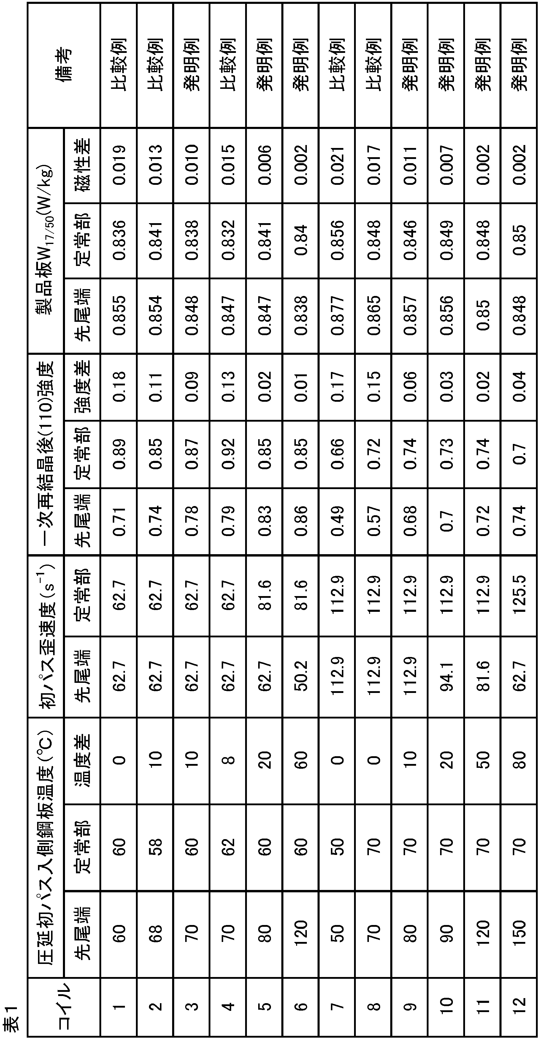
表2に示す成分を含有した鋼スラブを1200℃に加熱後、熱間圧延により板厚2.2mmの熱延コイルとした後、950℃、30秒の熱延板焼鈍を施した。次いで、タンデム圧延機(ロール径280mmφ4スタンド)を用いて、0.22mmまで圧下し冷延板とした。
一次再結晶焼鈍板にMgOを主剤とする焼鈍分離剤を塗布し、均熱温度1200℃、均熱時間5時間の二次再結晶焼鈍を施した。
得られた二次再結晶焼鈍板に、リン酸塩-クロム酸塩-コロイダルシリカを重量比3:1:2で含有する塗布液を塗布し、850℃、30秒の平坦化焼鈍を行なった後、定常部と先尾端のそれぞれから、30mm×280mmの試験片を総重量が500g以上となるように切り出し、エプスタイン試験により、鉄損W17/50(W/kg)を測定した。結果を表2に示す。

Claims (7)
- 質量%で、
C :0.01~0.10%、
Si:2.0~4.5%、
Mn:0.01~0.5%、
Al:0.0100%未満、
S :0.0070%以下、
Se:0.0070%以下、
N :0.0050%以下及び
O :0.0050%以下を含有し、
残部がFe及び不可避的不純物の成分組成を有する鋼スラブを、熱間圧延して熱延板とし、前記熱延板を焼鈍して熱延板焼鈍板とし、前記熱延板焼鈍板に1回又は中間焼鈍を挟んだ2回以上の冷間圧延を施して最終板厚の冷延板とし、前記冷延板に一次再結晶焼鈍及び二次再結晶焼鈍を施すことを含む、方向性電磁鋼板の製造方法であって、
少なくとも1回の冷間圧延は、総圧下率が80%以上であり、かつタンデム圧延機により行われ、
前記タンデム圧延機の少なくとも1つのスタンドで行われる圧延は、圧下率30%以上、かつ前記スタンドのワークロールへのかみ込み温度T0℃の条件で行われるが、
ただし、前記熱延板焼鈍板の先端及び尾端の一方又は両方の前記ワークロールへのかみ込み温度を、70℃以上、かつ前記T0℃よりも10℃以上高い温度とする、
方向性電磁鋼板の製造方法。 - 前記熱延板焼鈍板の先端及び尾端の一方又は両方の前記ワークロールへのかみ込み温度を、120℃以上、かつ前記T0℃よりも20℃以上高い温度とする、請求項1記載の方向性電磁鋼板の製造方法。
- 前記少なくとも1つのスタンドが、前記タンデム圧延機の最初のスタンドである、請求項1又は2の方向性電磁鋼板の製造方法。
- 前記タンデム圧延機の少なくとも1つのスタンドで行われる圧延が、歪み速度65s-1以上の条件で行われるが、ただし、前記熱延板焼鈍板の先端及び尾端の一方又は両方は歪み速度65s-1未満で圧延される、請求項1~3のいずれか一項記載の方向性電磁鋼板の製造方法。
- 鋼スラブが、さらに、質量%で、
Ni:0.005~1.50%、
Sn:0.01~0.50%、
Sb:0.005~0.50%、
Cu:0.01~0.50%、
Mo:0.01~0.50%、
P :0.0050~0.50%
Cr:0.01~1.50%、
Nb:0.0005~0.0200%、
B :0.0005~0.0200%及び
Bi:0.0005~0.0200%
からなる群より選ばれる1種又は2種以上を含有する、請求項1~4のいずれか一項に記載の方向性電磁鋼板の製造方法。 - 加熱装置及びタンデム圧延機を備えた設備列であって、
鋼板の長手方向の位置を検出する検出装置及び前記加熱装置の制御装置をさらに備え、
前記制御装置は、前記検出装置からの出力に基づいて、前記加熱装置を制御して、前記タンデム圧延機の少なくとも1つのスタンドのワークロールへのかみ込み温度を調整する、設備列。 - 前記加熱装置が、誘導加熱、通電加熱又は赤外加熱のいずれかの加熱方式を利用する、請求項6に記載の設備列。
Priority Applications (5)
| Application Number | Priority Date | Filing Date | Title |
|---|---|---|---|
| US18/003,343 US20230250503A1 (en) | 2020-06-30 | 2021-06-28 | Method of manufacturing grain-oriented electrical steel sheet and manufacturing line |
| KR1020227046306A KR102835138B1 (ko) | 2020-06-30 | 2021-06-28 | 방향성 전기 강판의 제조 방법 및 설비열 |
| JP2021560749A JP7276501B2 (ja) | 2020-06-30 | 2021-06-28 | 方向性電磁鋼板の製造方法及び設備列 |
| CN202180045783.3A CN115867680B (zh) | 2020-06-30 | 2021-06-28 | 取向性电磁钢板的制造方法和设备列 |
| EP21832682.5A EP4159336A4 (en) | 2020-06-30 | 2021-06-28 | Grain-oriented electromagnetic steel sheet production method and equipment line |
Applications Claiming Priority (2)
| Application Number | Priority Date | Filing Date | Title |
|---|---|---|---|
| JP2020113544 | 2020-06-30 | ||
| JP2020-113544 | 2020-06-30 |
Publications (1)
| Publication Number | Publication Date |
|---|---|
| WO2022004678A1 true WO2022004678A1 (ja) | 2022-01-06 |
Family
ID=79316291
Family Applications (1)
| Application Number | Title | Priority Date | Filing Date |
|---|---|---|---|
| PCT/JP2021/024424 Ceased WO2022004678A1 (ja) | 2020-06-30 | 2021-06-28 | 方向性電磁鋼板の製造方法及び設備列 |
Country Status (7)
| Country | Link |
|---|---|
| US (1) | US20230250503A1 (ja) |
| EP (1) | EP4159336A4 (ja) |
| JP (1) | JP7276501B2 (ja) |
| KR (1) | KR102835138B1 (ja) |
| CN (1) | CN115867680B (ja) |
| TW (1) | TWI779692B (ja) |
| WO (1) | WO2022004678A1 (ja) |
Families Citing this family (2)
| Publication number | Priority date | Publication date | Assignee | Title |
|---|---|---|---|---|
| WO2023277169A1 (ja) * | 2021-06-30 | 2023-01-05 | Jfeスチール株式会社 | 方向性電磁鋼板の製造方法及び方向性電磁鋼板製造用圧延設備 |
| JPWO2025047016A1 (ja) * | 2023-08-30 | 2025-03-06 |
Citations (11)
| Publication number | Priority date | Publication date | Assignee | Title |
|---|---|---|---|---|
| JPS4839338A (ja) | 1971-09-27 | 1973-06-09 | ||
| JPS5016610A (ja) | 1973-06-18 | 1975-02-21 | ||
| JPS5079442A (ja) | 1973-11-17 | 1975-06-27 | ||
| JPH05329510A (ja) * | 1992-06-02 | 1993-12-14 | Nippon Steel Corp | 鋼材の加熱圧延方法 |
| JPH08253816A (ja) | 1995-03-15 | 1996-10-01 | Nippon Steel Corp | 超高磁束密度一方向性電磁鋼板の製造方法 |
| JP2000129356A (ja) | 1998-10-28 | 2000-05-09 | Kawasaki Steel Corp | 方向性電磁鋼板の製造方法 |
| JP2002178024A (ja) * | 2000-12-12 | 2002-06-25 | Kawasaki Steel Corp | シートバー加熱方法 |
| JP2004058128A (ja) * | 2002-07-31 | 2004-02-26 | Jfe Steel Kk | 鋼管の圧延温度制御方法および装置 |
| JP2006187779A (ja) * | 2005-01-04 | 2006-07-20 | Kobe Steel Ltd | 鋳片の直送圧延方法 |
| JP2012184497A (ja) | 2011-02-17 | 2012-09-27 | Jfe Steel Corp | 方向性電磁鋼板の製造方法 |
| JP2016089198A (ja) * | 2014-10-31 | 2016-05-23 | Jfeスチール株式会社 | 磁気特性に優れる方向性電磁鋼板の製造方法 |
Family Cites Families (8)
| Publication number | Priority date | Publication date | Assignee | Title |
|---|---|---|---|---|
| US5666842A (en) * | 1993-07-22 | 1997-09-16 | Kawasaki Steel Corporation | Method of cold rolling grain-oriented silicon steel sheet having excellent and uniform magnetic characteristics along rolling direction of coil and a roll cooling controller for cold rolling mill using the cold rolling method |
| JP2951852B2 (ja) * | 1994-09-30 | 1999-09-20 | 川崎製鉄株式会社 | 磁気特性に優れる一方向性珪素鋼板の製造方法 |
| JP4612082B2 (ja) | 1998-08-07 | 2011-01-12 | 株式会社平和 | パチンコ機の賞球払出装置 |
| JP2001215925A (ja) | 2000-01-31 | 2001-08-10 | Matsushita Graphic Communication Systems Inc | 画像記録装置 |
| JP6098772B2 (ja) * | 2014-11-27 | 2017-03-22 | Jfeスチール株式会社 | 方向性電磁鋼板の製造方法 |
| CN107429307B (zh) * | 2015-04-02 | 2019-05-14 | 新日铁住金株式会社 | 单向性电磁钢板的制造方法 |
| CN108699621B (zh) * | 2016-03-09 | 2020-06-26 | 杰富意钢铁株式会社 | 取向性电磁钢板的制造方法 |
| CN112930412A (zh) * | 2018-10-31 | 2021-06-08 | 杰富意钢铁株式会社 | 无取向性电磁钢板及其制造方法以及电动机铁心及其制造方法 |
-
2021
- 2021-06-28 KR KR1020227046306A patent/KR102835138B1/ko active Active
- 2021-06-28 WO PCT/JP2021/024424 patent/WO2022004678A1/ja not_active Ceased
- 2021-06-28 EP EP21832682.5A patent/EP4159336A4/en active Pending
- 2021-06-28 JP JP2021560749A patent/JP7276501B2/ja active Active
- 2021-06-28 CN CN202180045783.3A patent/CN115867680B/zh active Active
- 2021-06-28 US US18/003,343 patent/US20230250503A1/en active Pending
- 2021-06-29 TW TW110123847A patent/TWI779692B/zh active
Patent Citations (11)
| Publication number | Priority date | Publication date | Assignee | Title |
|---|---|---|---|---|
| JPS4839338A (ja) | 1971-09-27 | 1973-06-09 | ||
| JPS5016610A (ja) | 1973-06-18 | 1975-02-21 | ||
| JPS5079442A (ja) | 1973-11-17 | 1975-06-27 | ||
| JPH05329510A (ja) * | 1992-06-02 | 1993-12-14 | Nippon Steel Corp | 鋼材の加熱圧延方法 |
| JPH08253816A (ja) | 1995-03-15 | 1996-10-01 | Nippon Steel Corp | 超高磁束密度一方向性電磁鋼板の製造方法 |
| JP2000129356A (ja) | 1998-10-28 | 2000-05-09 | Kawasaki Steel Corp | 方向性電磁鋼板の製造方法 |
| JP2002178024A (ja) * | 2000-12-12 | 2002-06-25 | Kawasaki Steel Corp | シートバー加熱方法 |
| JP2004058128A (ja) * | 2002-07-31 | 2004-02-26 | Jfe Steel Kk | 鋼管の圧延温度制御方法および装置 |
| JP2006187779A (ja) * | 2005-01-04 | 2006-07-20 | Kobe Steel Ltd | 鋳片の直送圧延方法 |
| JP2012184497A (ja) | 2011-02-17 | 2012-09-27 | Jfe Steel Corp | 方向性電磁鋼板の製造方法 |
| JP2016089198A (ja) * | 2014-10-31 | 2016-05-23 | Jfeスチール株式会社 | 磁気特性に優れる方向性電磁鋼板の製造方法 |
Non-Patent Citations (1)
| Title |
|---|
| See also references of EP4159336A4 |
Also Published As
| Publication number | Publication date |
|---|---|
| TW202202633A (zh) | 2022-01-16 |
| EP4159336A1 (en) | 2023-04-05 |
| KR20230019158A (ko) | 2023-02-07 |
| CN115867680B (zh) | 2025-09-16 |
| TWI779692B (zh) | 2022-10-01 |
| EP4159336A4 (en) | 2024-04-03 |
| JP7276501B2 (ja) | 2023-05-18 |
| US20230250503A1 (en) | 2023-08-10 |
| CN115867680A (zh) | 2023-03-28 |
| KR102835138B1 (ko) | 2025-07-16 |
| JPWO2022004678A1 (ja) | 2022-01-06 |
Similar Documents
| Publication | Publication Date | Title |
|---|---|---|
| JP7392849B2 (ja) | 方向性電磁鋼板の製造方法および電磁鋼板製造用圧延設備 | |
| US12344909B2 (en) | Method for producing grain-oriented electrical steel sheet and cold-rolling facility | |
| WO2011111862A1 (ja) | 方向性電磁鋼板の製造方法 | |
| JP7028215B2 (ja) | 方向性電磁鋼板の製造方法 | |
| JP7276501B2 (ja) | 方向性電磁鋼板の製造方法及び設備列 | |
| JP7616242B2 (ja) | 方向性電磁鋼板の製造方法及び方向性電磁鋼板製造用圧延設備 | |
| JP7276502B2 (ja) | 方向性電磁鋼板の製造方法及び設備列 | |
| US12480176B2 (en) | Method of manufacturing grain-oriented electrical steel sheet | |
| US20260081056A1 (en) | Method for producing grain-oriented electrical steel sheet, and induction heating device | |
| WO2024204818A1 (ja) | 方向性電磁鋼板の製造方法、方向性電磁鋼板の製造設備列、及び方向性電磁鋼板用熱延板 | |
| WO2023277169A1 (ja) | 方向性電磁鋼板の製造方法及び方向性電磁鋼板製造用圧延設備 | |
| JP2023116341A (ja) | 方向性電磁鋼板の製造方法 |
Legal Events
| Date | Code | Title | Description |
|---|---|---|---|
| ENP | Entry into the national phase |
Ref document number: 2021560749 Country of ref document: JP Kind code of ref document: A |
|
| 121 | Ep: the epo has been informed by wipo that ep was designated in this application |
Ref document number: 21832682 Country of ref document: EP Kind code of ref document: A1 |
|
| WWE | Wipo information: entry into national phase |
Ref document number: 202217075927 Country of ref document: IN |
|
| ENP | Entry into the national phase |
Ref document number: 20227046306 Country of ref document: KR Kind code of ref document: A |
|
| ENP | Entry into the national phase |
Ref document number: 2021832682 Country of ref document: EP Effective date: 20230102 |
|
| NENP | Non-entry into the national phase |
Ref country code: DE |
|
| WWG | Wipo information: grant in national office |
Ref document number: 202180045783.3 Country of ref document: CN |