WO2022004768A1 - Procédé de liaison et dispositif de liaison - Google Patents
Procédé de liaison et dispositif de liaison Download PDFInfo
- Publication number
- WO2022004768A1 WO2022004768A1 PCT/JP2021/024682 JP2021024682W WO2022004768A1 WO 2022004768 A1 WO2022004768 A1 WO 2022004768A1 JP 2021024682 W JP2021024682 W JP 2021024682W WO 2022004768 A1 WO2022004768 A1 WO 2022004768A1
- Authority
- WO
- WIPO (PCT)
- Prior art keywords
- joining
- horn
- cushioning
- horn portion
- members
- Prior art date
- Legal status (The legal status is an assumption and is not a legal conclusion. Google has not performed a legal analysis and makes no representation as to the accuracy of the status listed.)
- Ceased
Links
Images



Classifications
-
- B—PERFORMING OPERATIONS; TRANSPORTING
- B23—MACHINE TOOLS; METAL-WORKING NOT OTHERWISE PROVIDED FOR
- B23K—SOLDERING OR UNSOLDERING; WELDING; CLADDING OR PLATING BY SOLDERING OR WELDING; CUTTING BY APPLYING HEAT LOCALLY, e.g. FLAME CUTTING; WORKING BY LASER BEAM
- B23K20/00—Non-electric welding by applying impact or other pressure, with or without the application of heat, e.g. cladding or plating
- B23K20/10—Non-electric welding by applying impact or other pressure, with or without the application of heat, e.g. cladding or plating making use of vibrations, e.g. ultrasonic welding
-
- B—PERFORMING OPERATIONS; TRANSPORTING
- B23—MACHINE TOOLS; METAL-WORKING NOT OTHERWISE PROVIDED FOR
- B23K—SOLDERING OR UNSOLDERING; WELDING; CLADDING OR PLATING BY SOLDERING OR WELDING; CUTTING BY APPLYING HEAT LOCALLY, e.g. FLAME CUTTING; WORKING BY LASER BEAM
- B23K20/00—Non-electric welding by applying impact or other pressure, with or without the application of heat, e.g. cladding or plating
- B23K20/10—Non-electric welding by applying impact or other pressure, with or without the application of heat, e.g. cladding or plating making use of vibrations, e.g. ultrasonic welding
- B23K20/106—Features related to sonotrodes
-
- B—PERFORMING OPERATIONS; TRANSPORTING
- B23—MACHINE TOOLS; METAL-WORKING NOT OTHERWISE PROVIDED FOR
- B23K—SOLDERING OR UNSOLDERING; WELDING; CLADDING OR PLATING BY SOLDERING OR WELDING; CUTTING BY APPLYING HEAT LOCALLY, e.g. FLAME CUTTING; WORKING BY LASER BEAM
- B23K20/00—Non-electric welding by applying impact or other pressure, with or without the application of heat, e.g. cladding or plating
- B23K20/22—Non-electric welding by applying impact or other pressure, with or without the application of heat, e.g. cladding or plating taking account of the properties of the materials to be welded
- B23K20/227—Non-electric welding by applying impact or other pressure, with or without the application of heat, e.g. cladding or plating taking account of the properties of the materials to be welded with ferrous layer
- B23K20/2275—Non-electric welding by applying impact or other pressure, with or without the application of heat, e.g. cladding or plating taking account of the properties of the materials to be welded with ferrous layer the other layer being aluminium
-
- B—PERFORMING OPERATIONS; TRANSPORTING
- B23—MACHINE TOOLS; METAL-WORKING NOT OTHERWISE PROVIDED FOR
- B23K—SOLDERING OR UNSOLDERING; WELDING; CLADDING OR PLATING BY SOLDERING OR WELDING; CUTTING BY APPLYING HEAT LOCALLY, e.g. FLAME CUTTING; WORKING BY LASER BEAM
- B23K2101/00—Articles made by soldering, welding or cutting
- B23K2101/34—Coated articles ; Surface treated articles
- B23K2101/35—Surface treated articles
-
- B—PERFORMING OPERATIONS; TRANSPORTING
- B23—MACHINE TOOLS; METAL-WORKING NOT OTHERWISE PROVIDED FOR
- B23K—SOLDERING OR UNSOLDERING; WELDING; CLADDING OR PLATING BY SOLDERING OR WELDING; CUTTING BY APPLYING HEAT LOCALLY, e.g. FLAME CUTTING; WORKING BY LASER BEAM
- B23K2103/00—Materials to be soldered, welded or cut
- B23K2103/02—Iron or ferrous alloys
- B23K2103/04—Steel or steel alloys
-
- B—PERFORMING OPERATIONS; TRANSPORTING
- B23—MACHINE TOOLS; METAL-WORKING NOT OTHERWISE PROVIDED FOR
- B23K—SOLDERING OR UNSOLDERING; WELDING; CLADDING OR PLATING BY SOLDERING OR WELDING; CUTTING BY APPLYING HEAT LOCALLY, e.g. FLAME CUTTING; WORKING BY LASER BEAM
- B23K2103/00—Materials to be soldered, welded or cut
- B23K2103/18—Dissimilar materials
- B23K2103/20—Ferrous alloys and aluminium or alloys thereof
-
- B—PERFORMING OPERATIONS; TRANSPORTING
- B23—MACHINE TOOLS; METAL-WORKING NOT OTHERWISE PROVIDED FOR
- B23K—SOLDERING OR UNSOLDERING; WELDING; CLADDING OR PLATING BY SOLDERING OR WELDING; CUTTING BY APPLYING HEAT LOCALLY, e.g. FLAME CUTTING; WORKING BY LASER BEAM
- B23K2103/00—Materials to be soldered, welded or cut
- B23K2103/30—Organic materials
Definitions
- the present invention relates to a joining method and a joining device, and more particularly to a joining method for performing a joining process of a group of joining members.
- Patent Document 1 The applicant proposed to concentrate energy by utilizing sonic vibration and / or ultrasonic vibration by providing protrusions on at least a part of the joint surfaces of a plurality of metal members (see Patent Document 1).
- Patent Document proposes to support the horn at a plurality of places and apply sonic vibration and / or ultrasonic vibration to the horn from a plurality of directions to realize a joining process with a large amount of energy.
- Patent Documents 1, 2 and 3 are incorporated in the present application.
- an object of the present invention is to provide a joining method or the like suitable for improving the joining process by paying attention to the relationship between the horn portion and the joining member group.
- the first aspect of the present invention is a joining method for performing a joining process of a joining member group including a plurality of joining members, in which a horn portion provided in the joining device vibrates and / or superimposes with respect to the joining member group.
- a joining step of applying sonic vibration to perform a joining process of the joining member group in the joining step, the horn portion sonicates and vibrates the joining member group via a buffer member softer than the horn portion. / Or give ultrasonic vibration.
- the second aspect of the present invention is the joining method of the first aspect, in which the cushioning member is higher than the melting temperature in the joining step.
- the third aspect of the present invention is the joining method of the first or second aspect, and in the joining step, one of the joining members has a higher temperature than the cushioning member and the other joining member. Become.
- a fourth aspect of the present invention is the joining method according to any one of the first to third aspects, wherein at least one of the cushioning member and the joining member has a protrusion on a contact surface with another member. Be prepared.
- a fifth aspect of the present invention is the joining method according to any one of the first to fourth aspects, wherein at least one of the cushioning member and the joining member has a concave groove on a contact surface with another member. It is formed.
- the sixth aspect of the present invention is the joining method according to any one of the first to third aspects, and the cushioning member and the joining member are flat plates.
- the seventh aspect of the present invention is the joining method according to any one of the first to sixth aspects, wherein the plurality of joining members included in the joining member group includes two adjacent non-metal members and at least two adjacent non-metal members.
- a metal member is included between the non-metal member and the horn, and at least two adjacent non-metal members are joined in the joining step.
- An eighth aspect of the present invention is the joining method according to any one of the first to seventh aspects.
- the horn portion is supported at a plurality of support positions, and the horn portion is buffered.
- the contact portion in contact with the member is between the plurality of support positions.
- a ninth aspect of the present invention is a joining device that performs joining processing of a joining member group including a plurality of joining members, and includes a horn portion that applies sonic vibration and / or ultrasonic vibration to the joining member group.
- the horn portion applies sonic vibration and / or ultrasonic vibration to the joining member group via a cushioning member softer than the horn portion.
- the tenth aspect of the present invention is the joining device of the ninth aspect, and the cushioning member is higher than the melting temperature.
- the eleventh aspect of the present invention is the joining device according to the ninth or tenth aspect, and one of the joining members has a higher temperature than the cushioning member and the other joining member.
- the twelfth aspect of the present invention is the joining device according to any one of the ninth to eleventh aspects, wherein at least one of the cushioning member and the joining member has a protrusion on a contact surface with another member. Be prepared.
- the thirteenth aspect of the present invention is the joining device according to any one of the ninth to twelfth aspects, and at least one of the cushioning member and the joining member has a concave groove on a contact surface with another member. It is formed.
- the fourteenth aspect of the present invention is the joining device according to any one of the ninth to thirteenth aspects, and the cushioning member and the joining member are flat plates.
- the fifteenth aspect of the present invention is the joining device according to any one of the ninth to the fourteenth aspects, and the plurality of joining members included in the joining member group includes two adjacent non-metal members and at least two adjacent non-metal members.
- a metal member is included between the non-metal member and the horn, and at least two adjacent non-metal members are joined in the joining step.
- the sixteenth aspect of the present invention is the joining device according to any one of the ninth to fifteenth aspects, in which the horn portion is supported at a plurality of support positions in the joining processing portion, and the horn portion is the said.
- the contact portion in contact with the cushioning member is between the plurality of support positions.
- the present invention is a program for controlling a computer for controlling a joining device that performs joining processing using sonic vibration and / or ultrasonic vibration to realize each aspect of the present invention, and a program thereof. May be regarded as a computer-readable recording medium for recording.
- the invention of the present application may be regarded as preventing oxidation by performing the joining step in a nitrogen atmosphere.
- the cushioning member by using the cushioning member, it is possible to protect the horn portion and the joining member from damage and improve the joining process.
- FIG. 1 is for explaining the outline of the present invention.
- FIG. 2 is for explaining the outline of the present invention.
- FIG. 1 is a diagram for explaining the experimental results of the present invention.
- FIG. 2 is a diagram for explaining the experimental results of the present invention.
- FIG. 3 is a diagram for explaining the experimental results of the present invention. It is a figure for demonstrating an example of joining of ceramic superconducting materials.
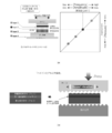
- FIG. 1 is a block diagram showing an example of (a) configuration of the joining device 1 according to the embodiment of the present invention, (b) a flow diagram showing an example of operation, and (c) for specifically explaining the operation. It is a figure.
- the joining device 1 includes a control unit 3, a joining processing unit 5, a moving unit 7, and a pressure adjusting unit 9.
- the joining processing unit 5 includes a horn unit 11, a first support unit 15, a second support unit 17, a first oscillator unit 19, a second oscillator unit 21, a first oscillation unit 23, and a second.
- the oscillation unit 25 and the connection signal wiring unit 27 are provided.
- the horn portion 11 includes a contact portion 13.
- the joining processing unit 5 performs joining processing of the first joining member 33 and the second joining member 35 (an example of the "joining member group" of the claims of the present application).
- the first joining member 33 is located above the second joining member 35 and is close to the joining processing portion 5.
- the second joint member 35 is provided with a projection 37 1 and 37 2 on the contact surface between the first joining member 33.
- EC Electrometic Concentration
- a cushioning member 31 exists between the first joining member 33 and the joining processing unit 5.
- the horn portion 11 is made of metal (for example, steel).
- the first joining member 33 is made of metal (for example, steel, high-tensile steel, etc.).
- the second joining member 35 may be a metal (for example, aluminum, steel, high-tensile steel, etc.) or a non-metal (ceramics, etc.).
- the cushioning member 31 is made of metal (aluminum or the like).
- the control unit 3 can control the operation of the joining device 1 by using the control signal.
- the moving unit 7 controls the vertical movement of the horn unit 11.
- the contact portion 13 comes into contact with the cushioning member 31 as the horn portion 11 descends.
- the pressure adjusting unit 9 adjusts the pressure by the contact unit 13.
- the joining processing unit 5 performs joining processing between the first joining member 33 and the second joining member 35 by using sonic vibration (vibration less than 20 kHz) and / or ultrasonic vibration (vibration of 20 kHz or more).
- the first oscillating unit 23 and the second oscillating unit 25 oscillate an electric signal corresponding to sound wave vibration and / or ultrasonic vibration using the connection signal wiring unit 27.
- the first oscillator unit 19 and the second oscillator unit 21 convert the electric signals of the first oscillation unit 23 and the second oscillation unit 25 into mechanical vibrations and transmit them to the horn unit 11, respectively.
- the horn portion 11 is supported by the first support portion 15 and the second support portion 17, and resonates.
- the joining processing unit 5 can realize the joining processing by utilizing the sonic vibration and / or the ultrasonic vibration.
- FIG. 1B is a flow chart showing an example of the operation of the joining device 1.
- the moving portion 7 lowers the horn portion 11 to bring the contact portion 13 into contact with the cushioning member 31 (step ST1).
- the pressure adjusting unit 9 starts pressurizing the cushioning member 31, the first joining member 33, and the second joining member 35 by the contact portion 13 (step ST2).
- the joining processing unit 5 oscillates the horn unit 11 (step ST3).
- the joining processing unit 5 determines whether or not to end the oscillation (step ST4). If the oscillation is not terminated, the process of step ST3 is continued.
- the joining processing unit 5 ends the oscillation of the horn unit 11, the pressure adjusting unit 9 stops the pressurization by the contact unit 13 (step ST5), and the moving unit 7 raises the horn. (Step ST6).
- FIG. 1C is a diagram illustrating an example of oscillation of the horn unit 11.
- the horn portion 11 has a plurality of nodal points (a portion where vibration is minimized) and a portion where vibration is maximized between the nodal points.
- the first support portion 15 and the second support portion 17 are provided at the nodal point.
- the contact portion 13 is provided at a portion where vibration is maximized.
- FIG. 1 (c) shows an example when the number of nodal points is an even number (4).
- the first oscillating unit 23 and the second oscillating unit 25 oscillate electric signals having opposite phases by using the connected signal wiring unit 27. Then, at each nodal point, expansion and contraction appear alternately. In this way, the joining processing unit 5 can perform joining processing of the first joining member 33 and the second joining member 35 by utilizing the sound wave vibration and / or the ultrasonic vibration.
- the joining process of the first joining member 33 and the second joining member 35 is performed via the cushioning member 31.
- the cushioning member 31 is, for example, one having a melting temperature lower than that of the metal of the horn portion 11 and the first joining member 33, and / or one that is softer than the metal of the horn portion 11 (for example, having a lower hardness).
- the cushioning member 31 is aluminum.
- aluminum has a unique characteristic in terms of material, has a wide range of applications, and is also effective in the semiconductor field.
- the horn portion 11 (steel) is used.
- the horn portion 11 (steel) has good sound energy transmission efficiency to the cushioning member 31 (aluminum).
- the sound energy between the horn portion 11 (steel) and the first joining member 33 (high-tensile steel) is utilized by utilizing the good transmission efficiency of the sound energy between the horn portion 11 (steel) and the cushioning member 31 (aluminum). Transmission efficiency will increase.
- the melting temperature of steel is 1300 ° C or higher, and the melting temperature of aluminum is about 660 ° C.
- the bonding processing unit 5 uses sound energy to excite the atoms of the first bonding member 33 (HITEN), which is a temperature higher than the melting temperature of the cushioning member 31 (aluminum) 660. Raise to above °C. This is not an external overheating, but an internal self-heating. This phenomenon can be confirmed by the fact that the high-tensile steel is burnt due to the high temperature of the high-tensile steel (see FIGS. 4 to 6). As a result, the first joining member 33 (high-tensile steel) and the second joining member 35 (aluminum) are joined.
- the horn portion 11 (steel) is strong against aluminum, does not burn, and is less likely to wear. Therefore, it is possible to reduce the cost. In this way, by making the melting temperature of the cushioning member 31 lower than the melting temperature of the horn portion 11 and / or making it soft, the horn is protected from damage (burning, wear, etc.) and is practically used. Become.
- the first joining member 33 is made of stainless steel
- the second joining member 35 is made of ceramics
- the cushioning member 31 is made of aluminum.
- EC protrusion joining is effective for joining steels to each other and joining steel and dissimilar metals, for example.
- Steel is hard and has a melting temperature of 1000 degrees or higher.
- sound energy is concentrated and processed by providing a protrusion on the contact surface with the other member in at least one of the cushioning member and the joining member (see Patent Document 1).
- it is effective to use EC projection joining in which a groove is formed on the contact surface with other members.
- the protrusion of the EC protrusion joint may be provided on the contact surface with the first joint member 33 in, for example, the cushioning member 31. Further, for example, in the first joining member 33, it may be provided on the contact surface with the cushioning member 31 and / or the contact surface with the second joining member 35. Further, for example, in the second joining member 35, it may be provided on the contact surface with the first joining member 33.
- the second joining member 35 forms a projection 37 1 and 37 2 by forming a recess in the contact surface to blow from the opposite side to the contact surface. To concentrate the sound energy by using the projections 37 1 and 37 2 can be self-heating to 660 ° C. or higher in the excited state of the atom.
- the present invention for example, it is possible to perform from diffusion bonding to dissolution bonding in which the region of sonic vibration (vibration less than 20 kHz, for example, 15 kHz) is used. Furthermore, as shown in FIG. 1, by using WPS of both support structures (the output of the double support structure / DSS junction device can be doubled. Double Power System), for example, 10,000 watts at a frequency of 15 kHz. It is possible to output a large output in a state where the pressure is small by using the sound wave vibration. With such a large output, it has become possible to join a wide range of materials from aluminum, which has a low melting temperature, to iron and ceramics, which have a high melting temperature.
- Double Power System for example, 10,000 watts at a frequency of 15 kHz.
- the cushioning member and / or the joining member may have a flat plate shape (a state in which protrusions or the like are not formed).
- the cushioning member 31 is soft and easy to join, the horn portion 11 and the first joining member 33 can be protected from damage. Further, the cushioning member 31 is directly hit by the horn portion 11, and the cushioning member 31 and the first joining member 33 are joined before the first joining member 33 and the second joining member 35, so that the horn portion 11 is used for the first step. 1
- the efficiency of transmitting sound energy to the joining member 33 is improved, and for example, steels can be joined to each other.
- the invention of the present application it is possible to join all materials including steel (for example, steels to each other, steels to different metals, steels to non-metals, steels to ceramics, etc.). Furthermore, it has become possible to secure the joint strength. Furthermore, it has become possible to melt and join each material. This will dramatically expand the scope and size of ultrasonic bonding applications and change the notion of sound energy potential. Furthermore, the cost of introducing equipment can be reduced, the life of the horn can be extended, and the cost of consumables can be reduced. In addition, the joining process is simplified, contributing to environmental issues and energy.
- the number of oscillator units may be one or three or more.
- FIG. 2 (a). From the top, there are a horn, a cushioning material, a first joining member, a second joining member, a receiving jig, and a base plate. The vibration direction of the horn is horizontal.
- the energy layer is between the cushioning material and the first joining member (layer 1), between the first joining member and the second joining member (joining surface, layer 2), and between the second joining member and the receiving jig (layer). 3) and between the receiving jig and the base plate (layer 4). It is necessary to control the energy layers of layers 1, 2, 3 and 4. In general, the lower the frequency and the smaller the amplitude, the higher the load. The higher the frequency and the larger the amplitude, the smaller the load. It is necessary to set the optimum joining conditions for layers 1 to 4 with respect to frequency, amplitude and load.
- high-tensile steel (first joining member) and aluminum (second joining member) aluminum can be adopted as the cushioning member to realize the joining process.
- High-tensile steel (first joining member) self-heats during vibration and becomes hotter than the upper and lower members, so that the joining process can be realized.
- first joining member high-tensile steel
- second joining member high-tensile steel
- the high-tensile steel (first joint member) is provided with a protrusion on the joint surface side with the high-tensile steel (second joint member).
- one surface of the joining member is hit with a columnar material to form a protrusion on the opposite surface (punching EC).
- the cushioning member (aluminum) is subjected to uneven groove processing on the joint surface side with the high-tensile steel (first joint member) to form a protrusion (concave and convex groove processing EC).
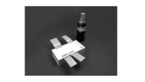
- FIG. 4 is a diagram showing an example of joining high-tensile steel (first joining member) and aluminum (second joining member) when aluminum is used as the cushioning member.
- the cushioning member is aluminum (A5052).
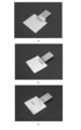
- FIG. 5A shows a state before joining.
- FIG. 5B shows the state after joining.
- FIG. 5 (c) is processed in a nitrogen atmosphere (N 2 environment), and as compared with FIG. 5 (b), a beautiful joining process can be realized with almost no oxidation.
- FIG. 6 shows the experimental results by the uneven groove processing EC.
- FIG. 6A shows a state in which the cushioning member has come off after joining.
- FIG. 6B shows the experimental results by the tensile experiment. The tensile strength was 12.500 kN (about 1.25 tons).
- a concave-convex groove is formed on the contact surface with the first joining member. That is, a concave groove is formed.
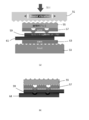
- FIG. 7 is a diagram for explaining an example of joining ceramic superconducting materials to each other.
- the joining member group is, from the top, a first metal plate 57, a first ceramics superconducting material 59, a second ceramics superconducting material 61, and a second metal plate 63.
- the first metal plate 57 and the second metal plate 63 are, for example, steel.
- the first metal plate 57 is provided with EC, and a protrusion is formed underneath.
- the melting temperature of the cushioning material aluminum 55 is lower than the melting temperature of the metal plate.
- the first ceramics superconducting material 59 and the second ceramics superconducting material 61 are in the form of a tape, and the surfaces in contact with each other are ceramics.
- FIG. 7B shows an example of a joined state.
- the first ceramics superconducting material 59 and the second ceramics superconducting material 61 are joined to each other by utilizing the momentary high temperature rise of the first metal plate 57 and / or the second metal plate 63.
- the joining layer can be controlled by the joining conditions of the joining device.
- 1 joining device 3 control section, 5 joining processing section, 7 moving section, 9 pressure adjusting section, 11 horn section, 13 contact section, 15 first support section, 17 second support section, 19 first oscillator section, 21 2nd oscillator part, 23 1st oscillation part, 25 2nd oscillation part, 27 connection signal wiring part, 31 cushioning member, 33 1st joining member, 35 2nd joining member, 51 horn, 53 anvil, 55 cushioning material aluminum , 57 1st metal plate, 59 1st ceramics superconducting material, 61 2nd ceramics superconducting material, 63 2nd metal plate
Landscapes
- Engineering & Computer Science (AREA)
- Mechanical Engineering (AREA)
- Pressure Welding/Diffusion-Bonding (AREA)
- Apparatuses For Generation Of Mechanical Vibrations (AREA)
Abstract
L'invention concerne un procédé de liaison et un procédé similaire permettant d'améliorer un processus de liaison tout en se concentrant sur la relation entre une unité de bras et un groupe d'éléments de liaison. Un dispositif de liaison 1 réalise un procédé de liaison d'un groupe d'éléments de liaison (premier élément de liaison 33 et second élément de liaison 35). Une unité de bras 11 d'une unité de traitement de liaison 5 applique une vibration sonique et/ou une vibration ultrasonique au groupe d'éléments de liaison par l'intermédiaire d'un élément d'amortissement 31. L'unité de bras 11 et le premier élément de liaison 33 sont en métal. L'élément d'amortissement 31 est plus souple que le métal de l'unité de bras 11.
Priority Applications (2)
| Application Number | Priority Date | Filing Date | Title |
|---|---|---|---|
| US18/001,903 US20230234161A1 (en) | 2020-06-30 | 2021-06-30 | Joining method and joining machine |
| DE112021003505.3T DE112021003505T5 (de) | 2020-06-30 | 2021-06-30 | Verbindungsverfahren und Verbindungsmaschine |
Applications Claiming Priority (2)
| Application Number | Priority Date | Filing Date | Title |
|---|---|---|---|
| JP2020-112393 | 2020-06-30 | ||
| JP2020112393A JP7032819B2 (ja) | 2020-06-30 | 2020-06-30 | 接合方法及び接合装置 |
Publications (1)
| Publication Number | Publication Date |
|---|---|
| WO2022004768A1 true WO2022004768A1 (fr) | 2022-01-06 |
Family
ID=79316546
Family Applications (1)
| Application Number | Title | Priority Date | Filing Date |
|---|---|---|---|
| PCT/JP2021/024682 Ceased WO2022004768A1 (fr) | 2020-06-30 | 2021-06-30 | Procédé de liaison et dispositif de liaison |
Country Status (4)
| Country | Link |
|---|---|
| US (1) | US20230234161A1 (fr) |
| JP (1) | JP7032819B2 (fr) |
| DE (1) | DE112021003505T5 (fr) |
| WO (1) | WO2022004768A1 (fr) |
Cited By (1)
| Publication number | Priority date | Publication date | Assignee | Title |
|---|---|---|---|---|
| US12407980B2 (en) | 2023-03-01 | 2025-09-02 | Qsc, Llc | Customizable waveguides and associated systems and methods |
Citations (3)
| Publication number | Priority date | Publication date | Assignee | Title |
|---|---|---|---|---|
| JPS5016307B1 (fr) * | 1967-07-06 | 1975-06-12 | ||
| JP2000176653A (ja) * | 1998-12-10 | 2000-06-27 | Arutekusu:Kk | 超音波振動接合装置 |
| JP2001038475A (ja) * | 1999-07-29 | 2001-02-13 | Denso Corp | 積層体の接合方法および電池 |
Family Cites Families (24)
| Publication number | Priority date | Publication date | Assignee | Title |
|---|---|---|---|---|
| US3914850A (en) * | 1973-11-05 | 1975-10-28 | Western Electric Co | Bonding of dissimilar workpieces to a substrate |
| JPS58100989A (ja) * | 1981-12-09 | 1983-06-15 | Toshiba Corp | 超音波溶接方法 |
| US4545519A (en) * | 1983-04-12 | 1985-10-08 | Fairchild Industries, Inc. | Method and apparatus for preventing tip sticking during welding operation |
| US4722824A (en) * | 1986-06-04 | 1988-02-02 | Fine Particle Technology Corp. | Method of joining green bodies prior to sintering |
| JPS642789A (en) * | 1987-06-22 | 1989-01-06 | Sky Alum Co Ltd | Manufacture of al welded can with coining pattern |
| US5011062A (en) * | 1990-05-09 | 1991-04-30 | Delco Electronics Corporation | Ultrasonic welding mask |
| JP3456293B2 (ja) * | 1995-03-17 | 2003-10-14 | 株式会社デンソー | 異種金属の超音波溶接方法 |
| JP3209133B2 (ja) * | 1997-02-28 | 2001-09-17 | 新神戸電機株式会社 | 多数枚積層した金属箔の超音波溶接方法 |
| EP1010492B1 (fr) * | 1998-12-10 | 2004-09-01 | Ultex Corporation | Procédé de soudage par vibration ultrasonique |
| US6464324B1 (en) * | 2000-01-31 | 2002-10-15 | Picojet, Inc. | Microfluid device and ultrasonic bonding process |
| US7784670B2 (en) * | 2004-01-22 | 2010-08-31 | Bondtech Inc. | Joining method and device produced by this method and joining unit |
| JP5377257B2 (ja) | 2009-12-02 | 2013-12-25 | 日立ビークルエナジー株式会社 | 二次電池および金属薄板の超音波溶接方法 |
| US8433433B2 (en) * | 2010-12-16 | 2013-04-30 | Lg Chem, Ltd. | System and method for determining whether an ultrasonic horn is aligned with an anvil |
| JP6156625B2 (ja) * | 2013-03-13 | 2017-07-05 | オムロン株式会社 | 金属部品どうしの接合構造及びその接合方法 |
| US10239150B2 (en) * | 2014-12-09 | 2019-03-26 | GM Global Technology Operations LLC | Ultrasonic welding of composites using C frame tooling |
| DE102015106265A1 (de) * | 2015-02-06 | 2016-08-11 | Auto-Kabel Management Gmbh | Ultraschallschweißvorrichtung sowie Verfahren zum Ultraschallschweißen |
| US10052713B2 (en) * | 2015-08-20 | 2018-08-21 | Ultex Corporation | Bonding method and bonded structure |
| CN108367504B (zh) * | 2015-12-18 | 2020-09-15 | 富士胶片株式会社 | 免疫层析试剂盒的制造方法 |
| US20170334016A1 (en) * | 2016-05-20 | 2017-11-23 | GM Global Technology Operations LLC | Method and apparatus to form a workpiece employing vibration welding |
| JP6635988B2 (ja) | 2017-08-01 | 2020-01-29 | 株式会社島精機製作所 | 編地の編成方法 |
| US20190151983A1 (en) * | 2017-11-20 | 2019-05-23 | GM Global Technology Operations LLC | Ultrasonic welding/brazing a steel workpiece over aluminum alloys |
| EP3778196A4 (fr) | 2018-04-13 | 2021-06-02 | Seidensha Electronics Co., Ltd. | Procédé de soudage aux ultrasons, structure soudée par un procédé de soudage aux ultrasons, et dispositif de soudage aux ultrasons |
| JP7205394B2 (ja) | 2018-07-06 | 2023-01-17 | 株式会社デンソー | クラッチ装置 |
| JP7335610B2 (ja) * | 2020-01-29 | 2023-08-30 | 株式会社アルテクス | めっき金属接合方法 |
-
2020
- 2020-06-30 JP JP2020112393A patent/JP7032819B2/ja active Active
-
2021
- 2021-06-30 WO PCT/JP2021/024682 patent/WO2022004768A1/fr not_active Ceased
- 2021-06-30 US US18/001,903 patent/US20230234161A1/en active Pending
- 2021-06-30 DE DE112021003505.3T patent/DE112021003505T5/de active Pending
Patent Citations (3)
| Publication number | Priority date | Publication date | Assignee | Title |
|---|---|---|---|---|
| JPS5016307B1 (fr) * | 1967-07-06 | 1975-06-12 | ||
| JP2000176653A (ja) * | 1998-12-10 | 2000-06-27 | Arutekusu:Kk | 超音波振動接合装置 |
| JP2001038475A (ja) * | 1999-07-29 | 2001-02-13 | Denso Corp | 積層体の接合方法および電池 |
Cited By (1)
| Publication number | Priority date | Publication date | Assignee | Title |
|---|---|---|---|---|
| US12407980B2 (en) | 2023-03-01 | 2025-09-02 | Qsc, Llc | Customizable waveguides and associated systems and methods |
Also Published As
| Publication number | Publication date |
|---|---|
| US20230234161A1 (en) | 2023-07-27 |
| JP7032819B2 (ja) | 2022-03-09 |
| JP2022011333A (ja) | 2022-01-17 |
| DE112021003505T5 (de) | 2023-04-20 |
Similar Documents
| Publication | Publication Date | Title |
|---|---|---|
| US10399274B2 (en) | Method for using transverse sonotrode in ultrasonic welding | |
| JP6553061B2 (ja) | 横並びに整列される変換器のための超音波ソノトロード | |
| US3184841A (en) | Method and apparatus employing vibratory energy for bonding metals | |
| JP2006506220A (ja) | 溶融されたスタック部材を持つ超音波ホーン組立体 | |
| CN108080781A (zh) | 用于超声波焊接工艺的喇叭 | |
| JP7032819B2 (ja) | 接合方法及び接合装置 | |
| JPH0232077B2 (fr) | ||
| US12318860B2 (en) | Plated metal bonding method and plated metal bonding apparatus | |
| Kumar et al. | Acoustic horn design for joining metallic wire with flat metallic sheet by ultrasonic vibrations. | |
| JP2002096180A (ja) | 超音波溶接機 | |
| JP6957054B1 (ja) | リベット接合方法及び接合処理装置 | |
| JP6861017B2 (ja) | 超音波接合方法および接合体 | |
| JP7264477B2 (ja) | 機械振動加工装置及び機械振動加工方法 | |
| JP7285005B2 (ja) | 機械振動加工装置及び機械振動加工方法 | |
| JPH115178A (ja) | 凹凸を有する金属材料の超音波接合 | |
| JP5395035B2 (ja) | 金属材の接合方法 | |
| JP5879582B2 (ja) | 超音波振動接合装置、及び超音波振動溶着装置 | |
| JP2005288457A (ja) | 異種金属材の超音波接合方法および超音波接合構造体 | |
| JP2003220482A (ja) | レーザ溶接方法及びレーザ溶接装置 | |
| Tsujino et al. | Welding characteristics of ultrasonic wire bonding using high-frequency vibration systems | |
| JP2023016355A (ja) | 接合方法 | |
| JP2022021709A (ja) | 接合方法及び接合装置 | |
| JP2024071281A (ja) | 超音波振動装置 | |
| WO2023149199A1 (fr) | Procédé de soudage par friction linéaire | |
| JP2006068812A (ja) | 超音波接合物の製造方法 |
Legal Events
| Date | Code | Title | Description |
|---|---|---|---|
| 121 | Ep: the epo has been informed by wipo that ep was designated in this application |
Ref document number: 21832685 Country of ref document: EP Kind code of ref document: A1 |
|
| 122 | Ep: pct application non-entry in european phase |
Ref document number: 21832685 Country of ref document: EP Kind code of ref document: A1 |