WO2022004792A1 - Unité d'entraînement, dispositif d'entraînement d'élément optique, module de caméra et dispositif équipé d'une caméra - Google Patents
Unité d'entraînement, dispositif d'entraînement d'élément optique, module de caméra et dispositif équipé d'une caméra Download PDFInfo
- Publication number
- WO2022004792A1 WO2022004792A1 PCT/JP2021/024767 JP2021024767W WO2022004792A1 WO 2022004792 A1 WO2022004792 A1 WO 2022004792A1 JP 2021024767 W JP2021024767 W JP 2021024767W WO 2022004792 A1 WO2022004792 A1 WO 2022004792A1
- Authority
- WO
- WIPO (PCT)
- Prior art keywords
- ois
- drive unit
- unit
- stage
- active
- Prior art date
- Legal status (The legal status is an assumption and is not a legal conclusion. Google has not performed a legal analysis and makes no representation as to the accuracy of the status listed.)
- Ceased
Links
Images


Classifications
-
- H—ELECTRICITY
- H02—GENERATION; CONVERSION OR DISTRIBUTION OF ELECTRIC POWER
- H02N—ELECTRIC MACHINES NOT OTHERWISE PROVIDED FOR
- H02N2/00—Electric machines in general using piezoelectric effect, electrostriction or magnetostriction
- H02N2/10—Electric machines in general using piezoelectric effect, electrostriction or magnetostriction producing rotary motion, e.g. rotary motors
- H02N2/12—Constructional details
Definitions
- the present invention relates to a drive unit, an optical element drive device, a camera module, and a camera mounting device.
- AF function Autofocus function
- OIS function Optical Image Stabilization
- a lens drive device having an AF function and an OIS function has an autofocus drive unit (hereinafter referred to as "AF drive unit”) for moving the lens unit in the optical axis direction and a plane in which the lens unit is orthogonal to the optical axis direction. It is provided with a runout correction drive unit (hereinafter referred to as “OIS drive unit”) for swinging the lens.
- AF drive unit autofocus drive unit
- OIS drive unit runout correction drive unit
- an ultrasonic motor type drive unit is applied to the AF drive unit and the OIS drive unit.
- the active element composed of the resonance portion and the passive element that moves relative to the active element come into contact with each other in an urged state, and both slide during driving. Therefore, there is a risk that the drive performance will be impaired over time due to wear.
- a frictional force that allows the passive element to move between the active element and the passive element is required, it is important to balance these because the contact portion tends to wear as the frictional force increases.
- An object of the present invention is to provide a highly reliable drive unit, optical element drive device, camera module, and camera-mounted device capable of suppressing deterioration of drive performance over time due to wear.
- the drive unit according to the present invention is Piezoelectric element that generates vibration by applying voltage,
- An active element (resonator) that has an arm portion that resonates with the vibration of the piezoelectric element and deforms, and converts the vibration of the piezoelectric element into linear motion.
- a drive unit comprising a passive element that is arranged in contact with the arm portion in an urged state and moves relative to the active element.
- the passive element has a coating layer on the contact surface with the active element. The hardness and shear strength of the coating layer are higher than those of the active element.
- the optical element driving device is Fixed part and A movable part that is arranged away from the fixed part and holds the optical element, A support portion that supports the movable portion with respect to the fixed portion, It is composed of the above-mentioned drive unit, and includes a drive unit for moving the movable portion with respect to the fixed portion.
- the camera module according to the present invention is With the above optical element drive device,
- the lens unit which is the optical element, and
- An imaging unit that captures a subject image imaged by the lens unit, and an imaging unit.
- a camera module With a camera module.
- the camera-mounted device is A camera-mounted device that is an information device or a transportation device. With the above camera module, It includes an image processing unit that processes the image information obtained by the camera module.
- a highly reliable drive unit an optical element drive device, a camera module, and a camera-mounted device capable of suppressing deterioration of drive performance over time due to wear are provided.
- FIG. 1A and 1B are views showing a smartphone equipped with a camera module according to an embodiment of the present invention.
- FIG. 2 is an external perspective view of the camera module.
- 3A and 3B are external perspective views of the optical element driving device according to the embodiment.
- FIG. 4 is an exploded perspective view of the optical element driving device.
- FIG. 5 is an exploded perspective view of the optical element driving device.
- FIG. 6 is a plan view showing the wiring structure of the base.
- 7A and 7B are perspective views of the OIS drive unit.
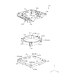
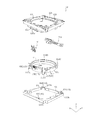
- FIG. 8 is an exploded perspective view of the OIS movable portion.
- FIG. 9 is an exploded perspective view of the OIS movable portion.
- FIG. 10 is an exploded perspective view of the OIS movable portion.
- 11A and 11B are perspective views of the AF drive unit.
- 12A and 12B are diagrams showing an automobile as a camera-mounted device for mounting an in-vehicle camera module.
- FIGS. 1A and 1B are diagrams showing a smartphone M (an example of a camera-mounted device) equipped with a camera module A according to an embodiment of the present invention.
- 1A is a front view of the smartphone M
- FIG. 1B is a rear view of the smartphone M.
- the smartphone M has a dual camera including two rear cameras OC1 and OC2.
- the camera module A is applied to the rear cameras OC1 and OC2.
- the camera module A has an AF function and an OIS function, automatically adjusts the focus when shooting a subject, and optically corrects the shake (vibration) that occurs during shooting to shoot an image without blurring. be able to.
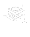
- FIG. 2 is an external perspective view of the camera module A.
- 3A and 3B are external perspective views of the optical element driving device 1 according to the embodiment.
- FIG. 3B shows a state in which FIG. 3A is rotated by 180 ° around the Z axis.
- an orthogonal coordinate system (X, Y, Z) will be used in the embodiments. Also in the figure described later, it is shown by a common Cartesian coordinate system (X, Y, Z).
- the X direction is the vertical direction (or the horizontal direction)
- the Y direction is the horizontal direction (or the vertical direction)
- the Z direction is the front-back direction. It will be installed. That is, the Z direction is the optical axis direction, the upper side (+ Z side) in the figure is the optical axis direction light receiving side, and the lower side ( ⁇ Z side) is the optical axis direction imaging side.
- the X direction and the Y direction orthogonal to the Z axis are referred to as "optical axis orthogonal direction”
- the XY plane is referred to as "optical axis orthogonal plane”.
- the camera module A includes an optical element driving device 1 that realizes an AF function and an OIS function, a lens unit 2 in which a lens is housed in a cylindrical lens barrel, and a lens.
- An image pickup unit 3 or the like for capturing an image of a subject imaged by the unit 2 is provided. That is, the optical drive device 1 is a so-called lens drive device that drives the lens unit 2 as an optical element.
- the imaging unit 3 is arranged on the optical axis direction imaging side of the optical element driving device 1.
- the image pickup unit 3 has, for example, an image sensor board 301, an image pickup element 302 mounted on the image sensor board 301, and a control unit 303.
- the image pickup device 302 is composed of, for example, a CCD (charge-coupled device) type image sensor, a CMOS (complementary metal oxide semiconductor) type image sensor, or the like, and captures an image of a subject imaged by the lens unit 2.
- the control unit 303 is composed of, for example, a control IC, and controls the drive of the optical element drive device 1.
- the optical element driving device 1 is mounted on the image sensor substrate 301 and is mechanically and electrically connected.
- the control unit 303 may be provided on the image sensor board 301, or may be provided on a camera-mounted device (in the embodiment, a smartphone M) on which the camera module A is mounted.
- the outside of the optical element drive device 1 is covered with a cover 24.
- the cover 24 is a covered square cylinder having a rectangular shape in a plan view when viewed from the optical axis direction. In the embodiment, the cover 24 has a square shape in a plan view.
- the cover 24 has a substantially circular opening 241 on the upper surface.
- the lens portion 2 faces the outside from the opening 241 of the cover 24, and is configured to project toward the light receiving side from the opening surface of the cover 24, for example, as it moves in the optical axis direction.
- the cover 24 is fixed to the base 21 (see FIG. 4) of the OIS fixing portion 20 of the optical element driving device 1, for example, by adhesion.
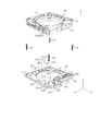
- FIG. 4 and 5 are exploded perspective views of the optical element driving device 1.
- FIG. 5 shows a state in which FIG. 4 is rotated by 180 ° around the Z axis.
- FIG. 4 shows a state in which the OIS drive unit 30 and the sensor board 22 are attached, and
- FIG. 5 shows a state in which the OIS drive unit 30 and the sensor board 22 are removed.
- the optical element driving device 1 includes an OIS movable portion 10 (second movable portion), an OIS fixing portion 20 (second fixed portion), and an OIS driving unit 30 (OIS driving unit 30). It includes an XY direction drive unit) and an OIS support unit 40 (second support unit).
- the OIS drive unit 30 has a first OIS drive unit 30X (X direction drive unit) and a second OIS drive unit 30Y (Y direction drive unit).
- the OIS movable portion 10 is a portion that swings in the plane orthogonal to the optical axis during runout correction.
- the OIS movable portion 10 includes an AF unit, a second stage 13, and X-direction reference balls 42A to 42C (see FIG. 8 and the like).
- the AF unit has an AF movable portion 11 (first movable portion), a first stage 12 (first fixed portion), an AF drive portion 14 (Z-direction drive portion), and an AF support portion 15 (first support portion) ( 8 to 10).
- the OIS fixing portion 20 is a portion to which the OIS movable portion 10 is connected via the OIS support portion 40.
- the OIS fixing portion 20 includes a base 21.
- the OIS movable portion 10 is arranged apart from the OIS fixing portion 20 in the optical axis direction, and is connected to the OIS fixing portion 20 via the OIS support portion 40. Further, the OIS movable portion 10 and the OIS fixing portion 20 are urged in a direction approaching each other by the OIS urging member 50.
- the OIS urging members 50 are arranged at the four corners in the plan view of the optical element driving device 1.
- the entire OIS movable portion 10 including the AF unit moves as a movable body.
- the AF unit moves as a movable body. That is, with respect to the movement in the X direction, the second stage 13 constitutes the OIS fixing portion 20 together with the base 21, and the X direction reference balls 42A to 42C function as the OIS support portion 40.
- the base 21 is formed of, for example, a polyarylate (PAR), a PAR alloy (for example, PAR / PC) in which a plurality of resin materials including PAR are mixed, or a molding material made of a liquid crystal polymer.
- the base 21 is a rectangular member in a plan view and has a circular opening 211 in the center.
- the base 21 has a first base portion 212 and a second base portion 213 forming the main surface of the base 21.
- the second base portion 213 is a portion of the OIS movable portion 10 protruding toward the optical axis direction imaging side, that is, the protruding portions 112A to 112D of the AF movable portion 11 and the AF motor fixing portion 125 of the first stage 12 (FIG. 8, FIG. (See FIG. 9).
- the second base portion 213 is formed to be one size larger in plan view than the protruding portions 112A to 112D and the AF motor fixing portion 125 so that interference does not occur during runout correction.
- the sensor substrate 22 is arranged so that a part (the portion corresponding to the protruding portions 112B and 112C) is exposed.
- the second base portion 213 is formed so as to be recessed with respect to the first base portion 212, whereby the moving stroke of the AF movable portion 11 is secured and the height of the optical element driving device 1 is reduced.
- the sensor substrate 22 is located in a region where the AF drive unit 14 and the OIS drive unit 30 are not arranged, that is, a region corresponding to one side (fourth side) of the rectangular shape of the base 21. It is provided. As a result, the feeding lines and signal lines for the magnetic sensors 25X, 25Y, and 25Z can be integrated, and the wiring structure in the base 21 can be simplified (see FIG. 6).
- the base 21 has an OIS motor fixing portion 215 in which the second OIS drive portion 30Y is arranged.
- the OIS motor fixing portion 215 is provided, for example, at a corner portion of the base 21, is formed so as to project from the first base portion 212 toward the light receiving side in the optical axis direction, and has a shape capable of holding the second OIS drive portion 30Y. Have.
- Terminal fittings 23A to 23C are arranged on the base 21 by, for example, insert molding.
- the terminal fitting 23A includes a power supply line to the AF drive unit 14 and the first OIS drive unit 30X.
- the terminal fitting 23A is exposed from, for example, the openings 216 formed at the four corners of the base 21, and is electrically connected to the OIS urging member 50.
- the power supply to the AF drive unit 14 and the first OIS drive unit 30X is performed via the OIS urging member 50.
- the terminal fitting 23B includes a feeding line (for example, 4 lines) and a signal line (for example, 6 lines) to the magnetic sensors 25X, 25Y, and 25Z.
- the terminal fitting 23B is electrically connected to a wiring (not shown) formed on the sensor substrate 22.
- the terminal fitting 23C includes a power supply line to the second OIS drive unit 30Y.
- the base 21 has Y-direction reference ball holding portions 217A to 217C in which Y-direction reference balls 41A to 41C constituting the OIS support portion 40 are arranged.
- the Y-direction reference ball holding portions 217A to 217C are formed by being recessed in a rectangular shape extending in the Y direction.
- the Y-direction reference ball holding portions 217A to 217C are formed in a substantially V-shaped (tapered shape) in cross section so that the groove width becomes narrower toward the bottom surface side.
- the Y-direction reference ball holding portions 217A and 217B are provided on the side (third side) where the second OIS driving unit 30Y of the base 21 is arranged, and the Y-direction reference ball holding portion 217C is provided.
- the OIS movable portion 10 (second stage 13) is supported at three points by the Y-direction reference balls 41A to 41C, which are provided on the side (fourth side) on which the sensor board 22 is arranged. There is.
- the sensor board 22 has wiring (not shown) including a feeding line and a signal line for the magnetic sensors 25X, 25Y, and 25Z.
- Magnetic sensors 25X, 25Y, and 25Z are mounted on the sensor board 22.
- the magnetic sensors 25X, 25Y, and 25Z are composed of, for example, a Hall element or a TMR (Tunnel Magneto Resistance) sensor, and are electrically connected to the terminal fitting 23B via wiring (not shown) formed on the sensor substrate 22. Will be done.
- an opening 221 is provided in a portion corresponding to the Y direction reference ball holding portion 217C.
- magnets 16X and 16Y are arranged at positions facing the magnetic sensors 25X and 25Y (see FIG. 10).
- the position detection unit including the magnetic sensors 25X and 25Y and the magnets 16X and 16Y detects the positions of the OIS movable portion 10 in the X and Y directions.
- a magnet 16Z is arranged at a position facing the magnetic sensor 25Z (see FIG. 10). The position of the AF movable portion 11 in the Z direction is detected by the position detection unit including the magnetic sensor 25Z and the magnet 16Z.
- an optical sensor such as a photoreflector is used to determine the X-direction and Y-direction positions of the OIS movable portion 10 and the Z-direction position of the AF movable portion 11. It may be detected.
- the OIS urging member 50 is composed of, for example, a tension coil spring, and connects the OIS movable portion 10 and the OIS fixing portion 20.
- one end of the OIS urging member 50 is connected to the terminal fitting 23A of the base 21, and the other end is connected to the wirings 17A and 17B of the first stage 12.
- the OIS urging member 50 receives a tensile load when the OIS movable portion 10 and the OIS fixing portion 20 are connected, and acts so that the OIS movable portion 10 and the OIS fixing portion 20 approach each other.
- the OIS movable portion 10 is oscillatedly held in the XY plane in a state of being urged in the optical axis direction (a state of being pressed against the base 21) by the OIS urging member 50.
- the OIS urging member 50 functions as a feeding line to the AF drive unit 14 and the first OIS drive unit 30X.
- the OIS support portion 40 supports the OIS movable portion 10 with respect to the OIS fixing portion 20 in a state of being separated in the optical axis direction.
- the OIS support portion 40 includes three Y-direction reference balls 41A to 41C interposed between the OIS movable portion 10 (second stage 13) and the base 21. Further, the OIS support portion 40 includes three X-direction reference balls 42A to 42C interposed between the first stage 12 and the second stage 13 in the OIS movable portion 10 (see FIG. 8 and the like).
- the OIS movable portion 10 is accurately shaken in the XY plane by restricting the rollable directions of the Y-direction reference balls 41A to 41C and the X-direction reference balls 42A to 42C (six in total). You can move it.
- the number of Y-direction reference balls and X-direction reference balls constituting the OIS support portion 40 can be appropriately changed.
- the OIS drive unit 30 is an actuator that moves the OIS movable unit 10 in the X direction and the Y direction.
- the OIS drive unit 30 includes a first OIS drive unit 30X (first XY direction drive unit) that moves the OIS movable unit 10 (AF unit only) in the X direction, and the entire OIS movable unit 10. It is composed of a second OIS drive unit 30Y (second XY direction drive unit) that moves in the Y direction.
- the first OIS drive unit 30X and the second OIS drive unit 30Y are composed of an ultrasonic motor.
- the first OIS drive unit 30X is fixed to the OIS motor fixing unit 124 along the X direction of the first stage 12 (see FIG. 9).
- the second OIS drive unit 30Y is fixed to the OIS motor fixing unit 215 of the base 21 so as to extend along the Y direction. That is, the first OIS drive unit 30X and the second OIS drive unit 30Y are arranged along the sides orthogonal to each other.
- FIGS. 7A and 7B The configuration of the OIS drive unit 30 is shown in FIGS. 7A and 7B.
- FIG. 7A shows a state in which each member of the OIS drive unit 30 is assembled
- FIG. 7B shows a state in which each member of the OIS drive unit 30 is disassembled.
- 7A and 7B show the second OIS drive unit 30Y, but the main configuration of the first OIS drive unit 30X, specifically, the configuration except for the shape of the OIS electrode 33 is the same.
- OIS drive unit 30 is treated as a diagram.
- the OIS drive unit 30 includes an OIS resonance unit 31, an OIS piezoelectric element 32, an OIS electrode 33, and an OIS power transmission unit 34.
- the driving force of the OIS drive unit 30 is transmitted to the second stage 13 via the OIS power transmission unit 34.
- the first OIS drive unit 30X is connected to the second stage 13 via the first OIS power transmission unit 34X
- the second OIS drive unit 30Y is connected to the second stage 13 via the second OIS power transmission unit 34Y. Is connected to the second stage 13.
- the OIS piezoelectric element 32 is, for example, a plate-shaped element made of a ceramic material, and generates vibration by applying a high frequency voltage. Two OIS piezoelectric elements 32 are arranged so as to sandwich the body portion 311 of the OIS resonance portion 31.
- the OIS electrode 33 sandwiches the OIS resonance portion 31 and the OIS piezoelectric element 32, and applies a voltage to the OIS piezoelectric element 32.
- the OIS electrode 33 of the first OIS drive unit 30X is electrically connected to the wiring 17A of the first stage 12, and the OIS electrode 33 of the second OIS drive unit 30Y is electrically connected to the terminal fitting 23C of the base 21. Be connected.
- the OIS resonance portion 31 is formed of a conductive material and resonates with the vibration of the OIS piezoelectric element 32 to convert the vibration motion into a linear motion.
- the OIS resonance portion 31 is formed by, for example, laser processing, etching processing, press processing, or the like of a metal plate.
- the OIS resonance portion 31 has a substantially rectangular body portion 311 sandwiched between the OIS piezoelectric elements 32, and two arm portions 312 extending in the X direction or the Y direction from the upper and lower portions of the body portion 311.
- the energizing unit 314 of the first OIS drive unit 30X is electrically connected to the wiring 17A of the first stage 12, and the energizing unit 314 of the second OIS drive unit 30Y is electrically connected to the terminal fitting 23C of the base 21. Be connected.
- the OIS piezoelectric element 32 is attached to the body portion 311 of the OIS resonance portion 31 from the thickness direction and is sandwiched by the OIS electrode 33, so that they are electrically connected to each other. For example, when one of the feeding paths is connected to the OIS electrode 33 and the other is connected to the energized portion 314 of the OIS resonance portion 31, a voltage is applied to the OIS piezoelectric element 32 and vibration is generated.
- the OIS resonance unit 31 has at least two resonance frequencies, and is deformed with different behaviors with respect to each resonance frequency.
- the overall shape of the OIS resonant portion 31 is set so that it deforms with different behaviors with respect to the two resonant frequencies.
- the different behaviors are the behavior of moving the OIS power transmission unit 34 forward in the X direction or the Y direction and the behavior of moving it backward.
- the OIS power transmission unit 34 is a chucking guide extending in one direction, one end of which is connected to the arm portion 312 of the OIS resonance portion 31, and the other end of which is connected to the second stage 13.
- the OIS power transmission unit 34 has an OIS motor contact portion 341, a stage fixing portion 343, and a connecting portion 342.
- the OIS motor contact portion 341 comes into contact with the free end portion of the arm portion 312 of the OIS resonance portion 31.
- the stage fixing portion 343 is arranged at the end of the OIS power transmission portion 34 and is fixed to the OIS chucking guide fixing portion 135 (see FIG. 8 and the like) of the second stage 13.
- the connecting portion 342 is a portion that connects the OIS motor contact portion 341 and the stage fixing portion 343, and is branched into two from the stage fixing portion 343 and is formed substantially parallel to each other.
- the width between the OIS motor contact portions 341 is set wider than the width between the free ends of the arm portions 312 of the OIS resonance portion 31.
- a separation portion 344 larger than the width of the connection end portion is interposed between the two connecting portions 342, thereby between the OIS motor contact portions 341.
- the width can be expanded.
- the separation portion 344 is integrally formed with, for example, the stage fixing portion 343.
- stage fixing portion 343 in the stage fixing portion 343, one side of the mounting portion of the connecting portion 342 is open, but the stage fixing portion 343 is the base of the connecting portion 342 (the stage fixing portion 343 side). It may have a structure that sandwiches the end portion of the). In this case, it is possible to prevent the connecting portion 342 from shifting and falling off over time, and the reliability is improved.
- the outer shape of the optical element drive device 1 is increased only by increasing the contact portion in the X direction or the Y direction.
- the moving stroke of the OIS movable portion 10 can be lengthened without any problem.
- the first OIS drive unit 30X is fixed to the OIS movable unit 10 (first stage 12), is connected to the second stage 13 via the OIS power transmission unit 34X, and is Y by the second OIS drive unit 30Y. At the time of runout correction in the direction, it moves together with the OIS movable portion 10.
- the second OIS drive unit 30Y is fixed to the OIS fixing unit 20 (base 21), connected to the second stage 13 via the OIS power transmission unit 34Y, and X by the first OIS drive unit 30X. Not affected by directional runout correction. That is, the movement of the OIS movable portion 10 by one OIS drive unit 30 is not hindered by the structure of the other OIS drive unit 30. Therefore, it is possible to prevent the OIS movable portion 10 from rotating around the Z axis, and the OIS movable portion 10 can be swung accurately in the XY plane.
- FIG. 9 shows a state in which FIG. 8 is rotated by 180 ° around the Z axis.
- FIG. 10 is a downward perspective view showing a state in which FIG. 8 is rotated by 180 ° around the Z axis.
- the AF drive unit 14 and the first OIS drive unit 30X are in a state of being removed from the first stage 12.
- the side on which the AF drive unit 14 is arranged is the “first side”
- the side on which the first OIS drive unit 30X is arranged is the “second side”.
- the side on which the second OIS drive unit 30Y is arranged is referred to as a "side”
- the remaining side is referred to as a "fourth side".
- the OIS movable unit 10 includes an AF movable unit 11, a first stage 12, a second stage 13, an AF drive unit 14, an AF support unit 15, and the like.
- the entire OIS movable portion 10 including the first stage 12 and the second stage 13 is a movable body, whereas the second stage 13 is the OIS fixed portion 20 for the movement in the X direction.
- the first stage 12 functions as an AF fixing portion that supports the AF movable portion 11.
- the AF movable portion 11 is a lens holder that holds the lens portion 2 (see FIG. 2), and moves in the optical axis direction at the time of focusing.
- the AF movable portion 11 is arranged radially inward with respect to the first stage 12 (AF fixing portion), and is supported in a state of being urged to the first stage 12 via the AF support portion 15.
- the AF movable portion 11 is formed of, for example, polyarylate (PAR), a PAR alloy in which a plurality of resin materials including PAR are mixed, a liquid crystal polymer, or the like.
- the AF movable portion 11 has a cylindrical lens accommodating portion 111.
- the lens portion 2 is fixed to the inner peripheral surface of the lens accommodating portion 111 by, for example, adhesion.
- the AF movable portion 11 has protruding portions 112A to 112D protruding outward in the radial direction and extending in the optical axis direction on the outer peripheral surface of the lens accommodating portion 111.
- the protrusions 112A to 112D are preferably arranged symmetrically with respect to the optical axis. In the present embodiment, protrusions 112A to 112D are provided around the optical axis at intervals of approximately 90 °.
- the protruding portions 112A to 112D project toward the optical axis direction imaging side from the lower surface of the lens accommodating portion 111, and abut against the second base portion 213 of the base 21 to cause the AF movable portion 11 to form an optical axis direction imaging side ( Restrict movement to the lower side).
- the protrusions 112A to 112D come into contact with the second base portion 213 of the base 21 in the reference state in which the AF drive portion 14 is not driven.
- the protrusions 112A and 112B on the AF drive unit 14 side hold the AF support unit 15 together with the first stage 12.
- One protruding portion 112A accommodates a first Z-direction reference ball 15A constituting the AF support portion 15.
- the other protruding portion 112B accommodates a second Z-direction reference ball 15B constituting the AF support portion 15.
- the protruding portions 112A and 112B accommodate the first preload balls 15C and the second preload balls 15D, which constitute the AF support portion 15, respectively.
- a magnet accommodating portion 114 accommodating the magnet 16Z for Z position detection is provided on the outer peripheral surface of the lens accommodating portion 111.
- the magnet 16Z is arranged in the magnet accommodating portion 114.
- a magnetic sensor 25Z for Z position detection is arranged at a position facing the magnet 16Z in the optical axis direction (see FIG. 4).
- the AF power transmission portion 144 is arranged between the protrusions 112A and 112B.
- the AF power transmission unit 144 is a chucking guide having a predetermined length in the Z direction, and has a side wall facing the X direction and projecting in the Y direction (-side).
- the arm portion 141b of the resonance portion 141 of the AF drive portion 14 abuts so as to expand the side wall of the AF power transmission portion 144, and the power of the AF drive portion 14 is transmitted to the AF movable portion 11.
- the side wall of the AF power transmission portion 144 functions as a leaf spring, so that the driving force generated by the deformation of the resonance portion 141 is efficiently transmitted.
- the structure of the AF power transmission unit 144 can be arbitrarily changed.
- the side wall may be folded back in the Z direction to form a leaf spring so as to be located inside the side wall in the X direction so that the urging force is exerted in the direction of pushing back the arm portion 141b of the AF drive portion 14.
- the driving force generated by the deformation of the resonance unit 141 is more efficiently transmitted to the AF power transmission unit 144.
- the AF power transmission unit 144 is composed of a separate member from the AF movable unit 11.
- the AF power transmission unit 144 has, for example, a U-shape in a plan view, and the bottom surface portion is fixed to the outer peripheral surface of the lens accommodating portion 111 in a state where the side surface portions face each other in the X direction.
- the AF power transmission unit 144 is made of, for example, a metal material.
- the first stage 12 supports the AF movable portion 11 via the AF support portion 15.
- the second stage 13 is arranged on the optical axis direction imaging side of the first stage 12 via the X-direction reference balls 42A to 42C.
- the first stage 12 moves in the X direction and the Y direction at the time of runout correction, and the second stage 13 moves only in the Y direction at the time of runout correction.
- the first stage 12 is a member having a substantially rectangular shape in a plan view seen from the optical axis direction, and is formed of, for example, a liquid crystal polymer.
- the first stage 12 has a substantially circular opening 121 in a portion corresponding to the AF movable portion 11.
- the opening 121 is formed with notches 122 corresponding to the protrusions 112A to 112D of the AF movable portion 11 and the magnet accommodating portion 114.
- the portion corresponding to the first OIS drive unit 30X (the outer surface of the side wall along the second side) can be arranged so that the first OIS drive unit 30X can be arranged without protruding outward in the radial direction.
- the portion corresponding to the second OIS drive unit 30Y (the outer surface of the side wall along the third side) is also formed to be recessed inward in the radial direction.
- the first stage 12 has X-direction reference ball holding portions 123A to 123C on the lower surface for holding the X-direction reference balls 42A to 42C.
- the X-direction reference ball holding portions 123A to 123C are formed by being recessed in a rectangular shape extending in the X direction.
- the X-direction reference ball holding portions 123A to 123C face the X-direction reference ball holding portions 133A to 133C of the second stage 13 in the Z direction.
- the X-direction reference ball holding portions 123A and 123B are formed in a substantially V-shaped (tapered shape) so that the groove width becomes narrower toward the bottom surface side, and the X-direction reference ball holding portions 123C are substantially U. It is formed in a character shape.
- an AF motor fixing portion 125 in which the AF drive portion 14 is arranged is formed on one side wall along the X direction (the side wall along the first side).
- the AF motor fixing portion 125 has an upper fixing plate (reference numeral omitted) and a lower fixing plate 125a, and the AF driving portion 14 is sandwiched between them.
- the AF resonance unit 141 is inserted into an insertion hole (reference numeral omitted) provided in the upper fixing plate and the lower fixing plate 125a, and is fixed by adhesion.
- the upper fixing plate is composed of a part of the wiring 17B, and the AF resonance portion 141 is electrically connected to the wiring 17B.
- magnets 16X and 16Y for XY position detection are arranged on one side wall along the Y direction (side wall along the fourth side).
- the magnet 16X is magnetized in the X direction
- the magnet 16Y is magnetized in the Y direction
- magnetic sensors 25X and 25Y for XY position detection are arranged at positions facing the magnets 16X and 16Y in the optical axis direction (see FIG. 4).
- wirings 17A and 17B are embedded in the first stage 12 by, for example, insert molding.
- the wirings 17A and 17B are arranged along the first side and the second side, for example.
- the wirings 17A and 17B are exposed from the four corners of the first stage 12, and one end of the OIS urging member 50 is connected to these portions. Power is supplied to the first OIS drive unit 30X via the wiring 17A, and power is supplied to the AF drive unit 14 via the wiring 17B.
- the second stage 13 is a member having a substantially rectangular shape in a plan view seen from the optical axis direction, and is formed of, for example, a liquid crystal polymer.
- the inner peripheral surface 131 of the second stage 13 is formed corresponding to the outer shape of the AF movable portion 11.
- the portions corresponding to the first OIS drive unit 30X and the second OIS drive unit 30Y are the same as those in the first stage 12. In addition, it is formed by denting inward in the radial direction.
- the second stage 13 has Y-direction reference ball holding portions 134A to 134C on the lower surface, which accommodate the Y-direction reference balls 41A to 41C.
- the Y-direction reference ball holding portions 134A to 134C are formed by being recessed in a rectangular shape extending in the Y direction.
- the Y-direction reference ball holding portions 134A to 134C face the Y-direction reference ball holding portions 217A to 217C of the base 21 in the Z direction.
- the Y-direction reference ball holding portions 134A and 134B are formed in a substantially V-shaped (tapered shape) so that the groove width becomes narrower toward the bottom surface side, and the Y-direction reference ball holding portion 134C is substantially U. It is formed in a character shape.
- the second stage 13 has X-direction reference ball holding portions 133A to 133C on the upper surface, which accommodate the X-direction reference balls 42A to 42C.
- the X-direction reference ball holding portions 133A to 133C are formed by being recessed in a rectangular shape extending in the X direction.
- the X-direction reference ball holding portions 133A to 133C face the X-direction reference ball holding portions 123A to 123C of the first stage 12 in the Z direction.
- the X-direction reference ball holding portions 133A to 133C are formed in a substantially V-shaped (tapered shape) in cross section so that the groove width becomes narrower toward the bottom surface side.
- the X-direction reference ball holding portions 133A and 133B are provided on the side (second side) where the first OIS driving unit 30X of the second stage 13 is arranged, and the X-direction reference ball holding portion is provided.
- the 133C is provided on the side (first side) where the AF drive unit 14 is arranged, and the first stage 12 is supported at three points by the X-direction reference balls 42A to 42C.
- the Y-direction reference balls 41A to 41C constituting the OIS support portion 40 are sandwiched by the Y-direction reference ball holding portions 217A to 217C of the base 21 and the Y-direction reference ball holding portions 134A to 134C of the second stage 13 by multipoint contact. Will be done. Therefore, the Y-direction reference balls 41A to 41C stably roll in the Y-direction.
- the X-direction reference balls 42A to 42C are sandwiched by the X-direction reference ball holding portions 133A to 133C of the second stage 13 and the X-direction reference ball holding portions 123A to 123C of the first stage 12 in a multi-point contact. Therefore, the X-direction reference balls 42A to 42C stably roll in the X-direction.
- the AF support portion 15 is a portion that supports the AF movable portion 11 with respect to the first stage 12 (AF fixing portion).
- the AF support portion 15 is composed of a first Z-direction reference ball 15A, a second Z-direction reference ball 15B, a first preload ball 15C, and a second preload ball 15D.
- the first Z-direction reference ball 15A, the second Z-direction reference ball 15B, the first preload ball 15C, and the second preload ball 15D are each a plurality of balls arranged side by side in the Z direction. It is composed of (here, 3 pieces).
- the intermediate ball is provided to secure the separation distance between the upper and lower balls, and may have a smaller diameter than the upper and lower balls.
- the AF drive unit 14 is an actuator that moves the AF movable unit 11 in the Z direction. Like the OIS drive unit 30, the AF drive unit 14 is composed of an ultrasonic motor. The AF drive unit 14 is fixed to the AF motor fixing unit 125 of the first stage 12 so that the arm unit 141b extends in the Z direction.
- FIGS. 11A and 11B The configuration of the AF drive unit 14 is shown in FIGS. 11A and 11B.
- FIG. 11A shows a state in which each member of the AF drive unit 14 is assembled
- FIG. 11B shows a state in which each member of the AF drive unit 14 is disassembled.
- the configuration of the AF drive unit 14 is almost the same as that of the OIS drive unit 30.
- the AF drive unit 14 includes an AF resonance unit 141, an AF piezoelectric element 142, an AF electrode 143, and an AF power transmission unit 144.
- the driving force of the AF driving unit 14 is transmitted to the AF movable unit 11 via the AF power transmission unit 144.
- the AF piezoelectric element 142 is, for example, a plate-shaped element made of a ceramic material, and generates vibration by applying a high frequency voltage.
- Two AF piezoelectric elements 142 are arranged so as to sandwich the body portion 141a of the AF resonance portion 141.
- the AF electrode 143 sandwiches the AF resonance portion 141 and the AF piezoelectric element 142, and applies a voltage to the AF piezoelectric element 142.
- the AF resonance portion 141 is formed of a conductive material and resonates with the vibration of the AF piezoelectric element 142 to convert the vibration motion into a linear motion.
- the AF resonance portion 141 is formed by, for example, laser processing, etching processing, press processing, or the like of a metal plate.
- the AF resonance portion 141 is a substantially rectangular body portion 141a sandwiched between the AF piezoelectric elements 142, two arm portions 141b extending in the Z direction from the body portion 141a, and a central portion of the body portion 141a.
- the current-carrying portion 141c extending in the Z direction from the center and electrically connected to the power feeding path (wiring 17B (upper fixing plate 125a) of the first stage 12) and the side opposite to the current-carrying portion 141c from the central portion of the body portion 141a.
- the two arm portions 141b have a symmetrical shape and are symmetrically deformed in resonance with the vibration of the AF piezoelectric element 142.
- the AF drive portion 14 has a stage fixing portion 141d extending to the AF drive portion 14.
- the two arm portions 141b extend in the Z direction and are arranged so as to sandwich the AF power transmission portion 144 at the free end portion.
- the AF piezoelectric element 142 is attached to the body portion 141a of the AF resonance portion 141 from the thickness direction and is sandwiched by the AF electrode 143 so that they are electrically connected to each other.
- a voltage is applied to the AF piezoelectric element 142 and vibration is generated.
- the AF resonance unit 141 has at least two resonance frequencies, and is deformed with different behaviors with respect to each resonance frequency.
- the AF resonance portion 141 is set to have an overall shape so as to be deformed with different behaviors with respect to the two resonance frequencies.
- the AF piezoelectric element 142 vibrates and the AF resonance unit 141 is deformed according to the frequency.
- the AF power transmission unit 144 is slid in the Z direction by the driving force of the AF drive unit 14. Along with this, the AF movable portion 11 moves in the Z direction, and focusing is performed. Since the AF support portion 15 is composed of balls, the AF movable portion 11 can smoothly move in the Z direction. Further, since the AF drive unit 14 and the AF power transmission unit 144 are only in contact with each other in an urged state, simply increasing the contact portion in the Z direction impairs the reduction in height of the optical element drive device 1. Without this, the moving stroke of the AF movable portion 11 can be easily lengthened.
- the OIS piezoelectric element 32 vibrates and the OIS resonance unit 31 is deformed according to the frequency.
- the driving force of the OIS driving unit 30 causes the OIS power transmitting unit 34 to slide in the X direction or the Y direction.
- the OIS movable portion 10 moves in the X direction or the Y direction, and runout correction is performed. Since the OIS support portion 40 is composed of balls, the OIS movable portion 10 can smoothly move in the X direction or the Y direction.
- the first stage 12 to the second stage 13 in which the first OIS drive unit 30X is arranged are arranged. Power is transmitted to.
- the ball 41 sandwiched between the second stage 13 and the base 21 cannot roll in the X direction, the position of the second stage 13 in the X direction with respect to the base 21 is maintained.
- the ball 42 sandwiched between the first stage 12 and the second stage 13 can roll in the X direction, the first stage 12 moves in the X direction with respect to the second stage 13. That is, the second stage 13 constitutes the OIS fixing portion 20, and the first stage 12 constitutes the OIS movable portion 10.
- the second OIS drive unit 30Y when the second OIS drive unit 30Y is driven and the OIS power transmission unit 34 moves in the Y direction, power is transmitted from the base 21 in which the second OIS drive unit 30Y is arranged to the second stage 13. To. At this time, since the ball 42 sandwiched between the first stage 12 and the second stage 13 cannot roll in the Y direction, the position of the first stage 12 in the Y direction with respect to the second stage is maintained. On the other hand, since the ball 41 sandwiched between the second stage 13 and the base 21 can roll in the Y direction, the second stage 13 moves in the Y direction with respect to the base 21. The first stage 12 also follows the second stage 13 and moves in the Y direction. That is, the base 21 constitutes the OIS fixing portion 20, and the AF unit including the first stage 12 and the second stage 13 constitutes the OIS movable portion 10.
- the OIS movable portion 10 swings in the XY plane, and runout correction is performed.
- the energizing voltage to the OIS drive unit 30 is set based on the detection signal indicating the angular vibration from the vibration detection unit (for example, a gyro sensor, not shown) so that the angular vibration of the camera module A is offset. Be controlled.
- the vibration detection unit for example, a gyro sensor, not shown
- the AF resonance unit 141 and the AF power transmission unit 144 are in contact with each other and slide with each other during driving.
- the OIS resonance unit 31 and the OIS power transmission unit 34 are in contact with each other and slide with each other during drive. That is, the AF drive unit 14 and the OIS drive unit 30 are ultrasonic motor type drive units that move the passive element relative to the active element.
- the active element is composed of an AF resonance unit 141 having an arm unit 141b that resonates with the vibration of the AF piezoelectric element 142 and deforms, and linearly moves the vibration motion of the AF piezoelectric element 142. Convert to.
- the passive element is composed of an AF power transmission unit 144 and is arranged so as to come into contact with the arm unit 141b in an urged state.
- the active element is composed of an OIS resonance unit 31 having an arm unit 31b that resonates with the vibration of the OIS piezoelectric element and deforms, and converts the vibration motion of the OIS piezoelectric element 32 into a linear motion.
- the passive element is composed of the OIS power transmission unit 34 and is arranged so as to come into contact with the arm unit 31b in a urged state.
- the passive element is moved to the combination of sliding members that slide with each other, that is, the combination of the AF resonance unit 141 and the AF power transmission unit 144, and the combination of the OIS resonance unit 31 and the OIS power transmission unit 34. It is required to have excellent wear resistance for a long period of time while exhibiting a frictional force to the extent possible. However, it is not easy to balance these because the frictional force and the wear resistance have contradictory characteristics, such that the wear resistance decreases when the frictional force is increased. As a result of diligent studies on the combination of sliding members, the present inventors have come up with a combination that can satisfy the requirements for the AF drive unit 14 and the OIS drive unit 30, and have completed the present invention. In the present embodiment, by applying the drive unit according to the present invention to the AF drive unit 14 and the OIS drive unit 30, the drive performance of the AF drive unit 14 and the OIS drive unit 30 is improved.
- the AF power transmission unit 144 which is a passive element, has a coating layer on the contact surface with the AF resonance unit 141, which is an active element, and the coating layer has a hardness and a shear strength higher than those of the AF resonance unit 141. big.
- the OIS power transmission unit 34 which is a passive element, has a coating layer on the contact surface with the OIS resonance unit 31, which is an active element, and the coating layer has a hardness and a shear strength higher than those of the OIS resonance unit 34. big.
- the active element side AF resonance portion 141, OIS resonance portion 31
- the wear resistance can be easily improved by controlling the surface state of the contact surface on the active element side.
- the stability of operation can be improved. That is, if a streak-like wear mark is formed on the contact surface due to local wear on the passive element side, unexpected operation may occur when the active side element is removed from the wear mark. It is possible to prevent such a problem from occurring.
- the contact surfaces of the AF resonance portion 141 and the OIS resonance portion 31, which are active elements, may be provided with a coating layer such as hard plating or coating, or may be surface-treated other than the coating layer. good.
- the coating layer may be formed directly on the active side base material which is the main material of the active element, or another member such as a plate having the coating layer may be attached to the active side base material. good.
- the active-side base material which is the main material of the active element, may be any metal having predetermined conductivity, shear strength, hardness, specific gravity, Young's modulus, etc., and for example, stainless steel is suitable.
- the Vickers hardness of the stainless steel rope is 180 to 400 HV.
- the AF power transmission unit 144 and the OIS power transmission unit 34 which are passive elements, are composed of a passive side base material which is a main material and a coating layer. By providing a coating layer having higher hardness and shear strength than the active element on the passive element side, wear of the passive element can be suppressed.
- the passive side base material preferably has a rigidity equal to or higher than that of the active side base material, and for example, stainless steel is suitable.
- the AF power transmission unit 144 and the OIS power transmission unit 34 can be imparted with self-restoring property to function as leaf springs, and it becomes easy to develop a desired frictional force between the active element and the passive element.
- the stainless steel rope forming the active side base material and the stainless steel rope forming the passive side base material may be of the same steel type or different steel types. For example, an appropriate steel grade is selected in consideration of the transmission of force from the active element to the passive element.
- the coating layer of the passive element for example, fine ceramics such as diamond-like carbon (DLC) and zirconia (ZnO 2) are suitable.
- DLC diamond-like carbon
- ZnO 2 zirconia
- the Vickers hardness of DLC is 1100 to 7000 HV
- the Vickers hardness of zirconia is 1200 to 1400 HV, both of which are harder than stainless steel. If the contact surfaces of the active element and the passive element are made of metals, agglutination may occur. Therefore, the coating layer is preferably formed of a material other than the metal.
- DLC when DLC is applied to the coating layer, the amount of wear of the active element and passive element when the urging load (friction force) is increased is smaller than that when zirconia is applied, and there is almost no change. It has been confirmed experimentally. Further, DLC is known to have self-lubricating property, and although it has a higher hardness than ceramics such as zirconia, it can be expected to have an effect of suppressing wear generated on the active side. From this, DLC is more suitable for the coating layer from the viewpoint that it can easily cope with the required urging load.
- the coating layer on the passive element side is made of a material harder than the active element, wear mainly occurs in the active element.
- the actual amount of wear is determined by a combination of multiple factors such as the hardness of the sliding member, compatibility with the mating material, and the environment in which it is used. When it is about 2.5 times or more of, it is considered that almost no wear of the coating layer occurs regardless of other factors. Therefore, by focusing on the wear resistance of the active element, the wear resistance of the drive unit can be improved.
- the active-side substrate of the AF resonance portion 141 and the OIS resonance portion 31 is flattened at least on the contact surface with the mating material (coating layer on the passive side). As a result, the surface texture is improved as compared with the state after processing, and the wear resistance of the active side base material is improved.
- Electropolishing is a method in which a polishing object is made a positive electrode and a DC current is passed through an electrolytic solution to melt and smooth the metal surface.
- mechanical polishing using a machine tool such as a grinder is performed to some extent. It is done after smoothing.
- Barrel polishing is a method in which an object to be polished, an abrasive, or the like is placed in a barrel tank and subjected to rotation or vibration for polishing.
- Plasma treatment is a method of chemically modifying the surface of an object by irradiating it with plasma, and has an advantage that it can be applied to a sheet-shaped object.
- the peak density Spd of the peak on the contact surface with the passive element is 200,000 to 1,500,000.
- the true contact area with the passive element is appropriately controlled, and cohesive wear including fretting wear and abstract wear can be suppressed, so that wear resistance is improved.
- the AF drive unit 14 (drive unit) according to the embodiment has an AF piezoelectric element 142 that generates vibration by applying a voltage, and an arm unit 141b that resonates with the vibration of the AF piezoelectric element 142 and deforms.
- the AF resonance portion 141 active element that converts the vibrational motion of the AF piezoelectric element 142 into a linear motion is arranged so as to be in contact with the arm portion 141b in an urged state, and is relatively relative to the AF resonance portion 141. It has a moving AF power transmission unit 144 (passive element).
- the OIS drive unit 30 (drive unit) has an OIS piezoelectric element 32 that generates vibration by applying a voltage and an arm portion 31b that resonates with the vibration of the OIS piezoelectric element 32 and deforms, and the vibration motion of the OIS piezoelectric element 32.
- the OIS resonance unit 31 active element that converts the (Passive element) and.
- the AF power transmission unit 144 and the OIS power transmission unit 34 which are passive elements, have a coating layer on the contact surface with the AF resonance unit 141 and the OIS resonance unit 31, which are active elements. The hardness and shear strength of the coating layer are larger than those of the active element.
- the coating layer of the passive element is preferably about 2.5 times or more the hardness of the active side base material which is the main material of the active element.
- the active side base material is formed of stainless steel and the coating layer of the passive element is formed of diamond-like carbon (DLC).
- the passive side base material is preferably made of stainless steel as in the active side base material.
- the active side base material has a flattening treatment on the contact surface with the passive element. As the flattening treatment, barrel polishing or electrolytic polishing is suitable. Further, the active side base material preferably has a peak density Spd of 200,000 to 1.5 million on the contact surface with the passive element.
- the AF drive unit 141 and the OIS drive unit 30 (drive unit) it is possible to suppress deterioration of drive performance over time due to wear and improve the reliability of the product to which the drive unit is applied. can.
- a smartphone M which is a mobile terminal with a camera
- the present invention uses the camera module and the image information obtained by the camera module. It can be applied to a camera-mounted device having an image processing unit for processing.
- Camera-mounted devices include information equipment and transportation equipment.
- the information device includes, for example, a mobile phone with a camera, a notebook computer, a tablet terminal, a portable game machine, a web camera, and an in-vehicle device with a camera (for example, a back monitor device and a drive recorder device).
- the transportation equipment includes, for example, an automobile.
- FIGS. 12A and 12B are diagrams showing an automobile V as a camera-mounted device for mounting an in-vehicle camera module VC (Vehicle Camera).
- 12A is a front view of the automobile V
- FIG. 12B is a rear perspective view of the automobile V.
- the automobile V is equipped with the camera module A described in the embodiment as the in-vehicle camera module VC.
- the vehicle-mounted camera module VC may be attached to the windshield toward the front or attached to the rear gate toward the rear, for example.
- This in-vehicle camera module VC is used for a back monitor, a drive recorder, a collision avoidance control, an automatic driving control, and the like.
- the optical element driving device 1 for driving the lens unit 2 as an optical element has been described, but the optical element to be driven may be an optical element other than the lens such as a mirror or a prism.
- Optical element drive device 10 OIS movable part (movable part) 12 First stage (fixed part) 13 Second stage 14 AF drive unit (drive unit) 141 AF resonance part (active element) 142 AF Piezoelectric element (active element) 143 AF electrode 144 AF power transmission unit (passive element) 15 AF support part 20 OIS fixing part (fixing part) 21 Base 30 OIS drive unit (drive unit) 31 OIS resonance part (active element) 32 OIS Piezoelectric element (active element) 33 OIS electrode 34 OIS power transmission unit (passive element) 40 OIS support 50 OIS urging member A Camera module M Smartphone (camera-mounted device)
Landscapes
- Lens Barrels (AREA)
- Adjustment Of Camera Lenses (AREA)
Abstract
La présente invention concerne une unité d'entraînement qui comprend : un élément piézoélectrique qui génère une oscillation par l'application d'une tension ; un élément actif qui a une section de bras qui se déforme par résonance avec l'oscillation de l'élément piézoélectrique, et qui convertit l'oscillation de l'élément piézoélectrique en un mouvement linéaire ; et un élément passif qui est disposé de façon à être en contact avec la section de bras dans un état sollicité, et qui se déplace par rapport à l'élément actif. L'élément passif comporte une couche de revêtement sur la surface en contact avec l'élément actif, et la dureté et la résistance au cisaillement de la couche de revêtement sont supérieures à celle de l'élément actif.
Applications Claiming Priority (2)
| Application Number | Priority Date | Filing Date | Title |
|---|---|---|---|
| US202063045859P | 2020-06-30 | 2020-06-30 | |
| US63/045,859 | 2020-06-30 |
Publications (1)
| Publication Number | Publication Date |
|---|---|
| WO2022004792A1 true WO2022004792A1 (fr) | 2022-01-06 |
Family
ID=79316326
Family Applications (1)
| Application Number | Title | Priority Date | Filing Date |
|---|---|---|---|
| PCT/JP2021/024767 Ceased WO2022004792A1 (fr) | 2020-06-30 | 2021-06-30 | Unité d'entraînement, dispositif d'entraînement d'élément optique, module de caméra et dispositif équipé d'une caméra |
Country Status (1)
| Country | Link |
|---|---|
| WO (1) | WO2022004792A1 (fr) |
Citations (6)
| Publication number | Priority date | Publication date | Assignee | Title |
|---|---|---|---|---|
| JP2000245179A (ja) * | 1998-12-21 | 2000-09-08 | Seiko Epson Corp | 圧電アクチュエータ、携帯機器および時計 |
| JP2001258276A (ja) * | 2000-03-10 | 2001-09-21 | Nikon Corp | 振動アクチュエータ |
| JP2011091957A (ja) * | 2009-10-23 | 2011-05-06 | Sharp Corp | 駆動装置、及びこれを備えた電子機器 |
| JP2015107001A (ja) * | 2013-11-29 | 2015-06-08 | 株式会社ニコン | 振動アクチュエータ、振動アクチュエータの制御装置、レンズ鏡筒及び電子機器 |
| JP2016201906A (ja) * | 2015-04-10 | 2016-12-01 | キヤノン株式会社 | 振動波モータ |
| JP2018050467A (ja) * | 2017-11-29 | 2018-03-29 | 株式会社ニコン | 振動アクチュエータ、レンズ鏡筒及び電子機器 |
-
2021
- 2021-06-30 WO PCT/JP2021/024767 patent/WO2022004792A1/fr not_active Ceased
Patent Citations (6)
| Publication number | Priority date | Publication date | Assignee | Title |
|---|---|---|---|---|
| JP2000245179A (ja) * | 1998-12-21 | 2000-09-08 | Seiko Epson Corp | 圧電アクチュエータ、携帯機器および時計 |
| JP2001258276A (ja) * | 2000-03-10 | 2001-09-21 | Nikon Corp | 振動アクチュエータ |
| JP2011091957A (ja) * | 2009-10-23 | 2011-05-06 | Sharp Corp | 駆動装置、及びこれを備えた電子機器 |
| JP2015107001A (ja) * | 2013-11-29 | 2015-06-08 | 株式会社ニコン | 振動アクチュエータ、振動アクチュエータの制御装置、レンズ鏡筒及び電子機器 |
| JP2016201906A (ja) * | 2015-04-10 | 2016-12-01 | キヤノン株式会社 | 振動波モータ |
| JP2018050467A (ja) * | 2017-11-29 | 2018-03-29 | 株式会社ニコン | 振動アクチュエータ、レンズ鏡筒及び電子機器 |
Similar Documents
| Publication | Publication Date | Title |
|---|---|---|
| JP7104365B2 (ja) | 光学素子駆動装置、カメラモジュール、及びカメラ搭載装置 | |
| JP2021170119A (ja) | レンズの振れ補正装置、カメラモジュール、及びカメラ搭載装置 | |
| JP7057516B2 (ja) | レンズ駆動装置、カメラモジュール、及びカメラ搭載装置 | |
| JP7075030B1 (ja) | 光学素子駆動装置、カメラモジュール、及びカメラ搭載装置 | |
| US20230408840A1 (en) | Optical-element driving device, camera module and camera-mounted device | |
| US20230408890A1 (en) | Optical element driving device, camera module, and camera-equipped device | |
| JP7075029B2 (ja) | レンズ駆動装置、カメラモジュール、及びカメラ搭載装置 | |
| WO2022004792A1 (fr) | Unité d'entraînement, dispositif d'entraînement d'élément optique, module de caméra et dispositif équipé d'une caméra | |
| JP7295447B2 (ja) | 駆動ユニット、光学素子駆動装置、カメラモジュール、及びカメラ搭載装置 | |
| JP7093050B2 (ja) | レンズ駆動装置、カメラモジュール、及びカメラ搭載装置 | |
| JP7372563B2 (ja) | レンズ駆動装置、カメラモジュール、及びカメラ搭載装置 | |
| JP7269521B2 (ja) | レンズ駆動装置、カメラモジュール、及びカメラ搭載装置 |
Legal Events
| Date | Code | Title | Description |
|---|---|---|---|
| 121 | Ep: the epo has been informed by wipo that ep was designated in this application |
Ref document number: 21832693 Country of ref document: EP Kind code of ref document: A1 |
|
| NENP | Non-entry into the national phase |
Ref country code: DE |
|
| 122 | Ep: pct application non-entry in european phase |
Ref document number: 21832693 Country of ref document: EP Kind code of ref document: A1 |
|
| NENP | Non-entry into the national phase |
Ref country code: JP |