WO2022004834A1 - Noyau de rotor - Google Patents
Noyau de rotor Download PDFInfo
- Publication number
- WO2022004834A1 WO2022004834A1 PCT/JP2021/024889 JP2021024889W WO2022004834A1 WO 2022004834 A1 WO2022004834 A1 WO 2022004834A1 JP 2021024889 W JP2021024889 W JP 2021024889W WO 2022004834 A1 WO2022004834 A1 WO 2022004834A1
- Authority
- WO
- WIPO (PCT)
- Prior art keywords
- region
- key
- shaft
- shaft hole
- contact
- Prior art date
- Legal status (The legal status is an assumption and is not a legal conclusion. Google has not performed a legal analysis and makes no representation as to the accuracy of the status listed.)
- Ceased
Links
Images


Classifications
-
- H—ELECTRICITY
- H02—GENERATION; CONVERSION OR DISTRIBUTION OF ELECTRIC POWER
- H02K—DYNAMO-ELECTRIC MACHINES
- H02K1/00—Details of the magnetic circuit
- H02K1/06—Details of the magnetic circuit characterised by the shape, form or construction
- H02K1/22—Rotating parts of the magnetic circuit
- H02K1/28—Means for mounting or fastening rotating magnetic parts on to, or to, the rotor structures
-
- H—ELECTRICITY
- H02—GENERATION; CONVERSION OR DISTRIBUTION OF ELECTRIC POWER
- H02K—DYNAMO-ELECTRIC MACHINES
- H02K1/00—Details of the magnetic circuit
- H02K1/06—Details of the magnetic circuit characterised by the shape, form or construction
- H02K1/22—Rotating parts of the magnetic circuit
- H02K1/27—Rotor cores with permanent magnets
- H02K1/2706—Inner rotors
- H02K1/272—Inner rotors the magnetisation axis of the magnets being perpendicular to the rotor axis
- H02K1/274—Inner rotors the magnetisation axis of the magnets being perpendicular to the rotor axis the rotor consisting of two or more circumferentially positioned magnets
- H02K1/2753—Inner rotors the magnetisation axis of the magnets being perpendicular to the rotor axis the rotor consisting of two or more circumferentially positioned magnets the rotor consisting of magnets or groups of magnets arranged with alternating polarity
- H02K1/276—Magnets embedded in the magnetic core, e.g. interior permanent magnets [IPM]
-
- H—ELECTRICITY
- H02—GENERATION; CONVERSION OR DISTRIBUTION OF ELECTRIC POWER
- H02K—DYNAMO-ELECTRIC MACHINES
- H02K1/00—Details of the magnetic circuit
- H02K1/06—Details of the magnetic circuit characterised by the shape, form or construction
- H02K1/22—Rotating parts of the magnetic circuit
- H02K1/32—Rotating parts of the magnetic circuit with channels or ducts for flow of cooling medium
-
- H—ELECTRICITY
- H02—GENERATION; CONVERSION OR DISTRIBUTION OF ELECTRIC POWER
- H02K—DYNAMO-ELECTRIC MACHINES
- H02K7/00—Arrangements for handling mechanical energy structurally associated with dynamo-electric machines, e.g. structural association with mechanical driving motors or auxiliary dynamo-electric machines
- H02K7/003—Couplings; Details of shafts
Definitions
- the present invention relates to a rotor core configured by laminating electromagnetic steel sheets.
- Patent Document 1 discloses a rotor core in which a key corresponding to a keyway of a shaft is formed in a shaft hole into which a shaft is inserted.
- the inner diameter of the shaft hole is larger than that of other parts in the peripheral portion of the key due to the formation of the key.
- the inner wall of the shaft hole does not come into contact with the shaft when the shaft is inserted into the shaft hole.
- one part of the inner wall of the shaft hole does not come into contact with the shaft, and the other part comes into contact with the shaft. Therefore, of the inner wall of the shaft hole, only the portion in contact with the shaft is pressed by the shaft. As a result, the portion of the inner wall that is pressed by the shaft expands radially outward of the shaft hole.
- the inner wall is stretched in the circumferential direction.
- the inner wall near the center of the region may approach the shaft and the shaft hole may be distorted.
- the inner diameter of the shaft hole in a portion adjacent to the key may be particularly large due to manufacturing reasons or the like.
- the inner wall around the boundary between the contact portion and the non-contact portion between the shaft and the inner wall is convex toward the center of the shaft hole.
- a rotor core composed of laminated electromagnetic steel sheets.
- the rotor core has a shape complementary to the shaft hole into which the shaft is inserted and the keyway formed in the shaft so as to extend in the axial direction of the shaft, and protrudes from the inner wall of the shaft hole to form the shaft. It has a ridge key, which extends along the central axis of the hole. The key is formed so that a gap is formed between the key and the key groove with the shaft inserted in the shaft hole.
- the radial distance which is the distance from the center of the shaft hole to the inner wall of the shaft hole, differs depending on the position in the circumferential direction of the shaft hole.
- the shaft hole is a key region in which the key is arranged, and is provided at a position adjacent to the key in the circumferential direction and sandwiching the key, and the radius distance is larger than the radius of the shaft.
- a total of three or more key regions and a diameter-expanded region having a radius distance larger than the radius of the shaft are provided.
- the key region and the enlarged diameter region are arranged side by side in the circumferential direction.
- the shaft hole is a region of the inner wall of the shaft hole sandwiched between the key region or the enlarged diameter region, and the shaft and the inner wall come into contact with each other when the shaft is inserted into the shaft hole. It has a contact area.
- the contact areas are arranged side by side at equal intervals in the circumferential direction.
- the schematic diagram which shows the state which the shaft hole of a rotor core is deformed.
- the schematic diagram which shows the state which the shaft hole in the rotor core of the comparative example was deformed.
- the rotor core 10 of the first embodiment will be described with reference to FIGS. 1 to 4.
- the rotor core 10 is arranged inside the cylindrical stator core to form an electric motor.
- FIG. 1 shows a cylindrical rotor core 10 and a shaft 90 that is a rotation axis of the rotor core 10.
- the rotor core 10 is configured by laminating a plurality of electromagnetic steel sheets processed into an annular shape.
- the rotor core 10 is manufactured by rotary lamination.
- a shaft hole 11 is formed by a hole opened in the center of each electrical steel sheet.
- FIG. 1 shows the central axis C1 of the shaft hole 11. A plurality of electrical steel sheets are laminated in the axial direction of the shaft hole 11.
- the shaft 90 is inserted into the shaft hole 11 of the rotor core 10.
- the shaft 90 has a cylindrical shape.
- the total length of the shaft 90 is larger than the length along the central axis C1 of the shaft hole 11.
- the shaft 90 is fixed to the rotor core 10 with both ends exposed from the shaft hole 11.
- the shaft 90 is formed with a key groove extending in the axial direction of the shaft 90.
- Two key grooves are formed on the shaft 90.
- One key groove is provided at a position on the opposite side of the other key groove, 180 degrees away from the circumferential direction of the shaft 90.
- the two key grooves are the first key groove 91 and the second key groove 92.
- FIG. 1 shows only the second keyway 92.
- FIG. 2 shows the rotor core 10 seen from one of both open ends of the shaft hole 11.
- the first oil passage 12A to the eighth oil passage 12H are formed radially outside the shaft hole 11.
- the first oil passage 12A to the eighth oil passage 12H are formed as holes penetrating the rotor core 10 in the axial direction of the central axis C1.
- the first oil passage 12A to the eighth oil passage 12H are arranged side by side at equal intervals in the circumferential direction of the shaft hole 11.
- the first oil passage 12A to the eighth oil passage 12H are passages through which oil used for cooling the rotor core 10 flows.
- the rotor core 10 includes a first connection path 14A that connects the first oil passage 12A and the shaft hole 11.
- the first connection path 14A is formed as a passage extending in a direction orthogonal to the central axis C1, that is, in the radial direction of the rotor core 10.
- the first connecting path 14A penetrates from the inner wall of the first oil passage 12A to the inner wall of the shaft hole 11 inside the rotor core 10.
- the rotor core 10 includes a second connecting path 14B to an eighth connecting path 14H connecting each oil passage of the second oil passage 12B to the eighth oil passage 12H with the shaft hole 11.
- the second connecting path 14B to the eighth connecting path 14H are formed as a passage extending in a direction orthogonal to the central axis C1 like the first connecting path 14A. As shown in FIG. 2, the first connection path 14A to the eighth connection path 14H are arranged radially with respect to the central axis C1. Oil can flow in and out between the first oil passage 12A to the eighth oil passage 12H and the shaft hole 11 via the first connecting passage 14A to the eighth connecting passage 14H.
- FIG. 2 schematically shows the first connection path 14A to the eighth connection path 14H.
- the first connecting path 14A to the eighth connecting path 14H do not have to be linear.
- the rotor core 10 is formed with a first magnet insertion hole 13A and a second magnet insertion hole 13B radially outside the first oil passage 12A to the eighth oil passage 12H.
- the first magnet insertion hole 13A and the second magnet insertion hole 13B are formed as holes penetrating the rotor core 10 along the central axis C1. Magnets are inserted into the first magnet insertion hole 13A and the second magnet insertion hole 13B.
- the shape of the shaft hole 11 will be described with reference to FIG.
- the planar shape of the shaft hole 11 in the cross section of the rotor core 10 orthogonal to the central axis C1 of the shaft hole 11 is equal at all positions from one open end to the other open end of the shaft hole 11.
- the rotor core 10 is shown by a solid line
- the shaft 90 is shown by a broken line.
- the shaft hole 11 has a first key 31 having a shape complementary to the first key groove 91 of the shaft 90 and a shape complementary to the second key groove 92.
- a second key 41 is provided.
- the first key 31 and the second key 41 project from the inner wall 20 of the shaft hole 11 toward the central axis C1.
- the first key 31 and the second key 41 are ridges extending along the central axis C1.
- the first key 31 is arranged at a position facing the second key 41.
- the shaft 90 is press-fitted into the shaft hole 11 of the rotor core 10. As will be described in detail later, the distance from the center of the shaft hole 11 to the inner wall 20 of the shaft hole 11 differs depending on the position in the circumferential direction of the shaft hole 11. Therefore, when the shaft 90 is press-fitted into the shaft hole 11, a portion where the shaft 90 contacts the inner wall 20 of the shaft hole 11 and a portion where a gap is formed between the shaft 90 and the inner wall 20 of the shaft hole 11. , There is.
- the first key 31 is inserted into the first key groove 91.
- the second key 41 is inserted into the second key groove 92.
- the first key 31 and the first key groove 91 are formed into a shape in which a gap is formed between the first key 31 and the first key groove 91 with the shaft 90 inserted in the shaft hole 11.
- the second key 41 and the second key groove 92 are formed into a shape in which a gap is formed between the second key 41 and the second key groove 92 with the shaft 90 inserted in the shaft hole 11. ..
- the range in which the first key 31 is located is defined as the first key area 30.
- the range where the second key 41 is located is defined as the second key area 40.
- FIG. 3 shows a virtual straight line extending in the radial direction of the shaft hole 11 through the central axis C1 as a alternate long and short dash line. Each alternate long and short dash line indicates the boundary between the regions.
- the first key area 30 is arranged at a position facing the second key area 40. On the plane shown in FIG. 3, the length of the inner wall 20 in the first key region 30 is equal to the length of the inner wall 20 in the second key region 40.
- the length of the line segment connecting one end and the other end of each region on the inner wall 20 is referred to as the width of the region.
- the width of the region corresponds to the length of the chord when the shaft hole 11 is considered as a circle.
- the width of the first key area 30 is the same as the width of the second key area 40.
- the portions on both sides adjacent to the first key region 30 in the circumferential direction of the shaft hole 11 are contact regions where the shaft 90 and the inner wall 20 come into contact with each other when the shaft 90 is inserted into the shaft hole 11.
- the portions on both sides adjacent to the second key region 40 in the circumferential direction are also contact regions where the shaft 90 and the inner wall 20 come into contact with each other when the shaft 90 is inserted into the shaft hole 11. That is, the shaft hole 11 includes four contact regions.
- the contact area adjacent to the first key area 30 in the clockwise direction is defined as the first contact area 21A.
- the first contact region 21A, the second contact region 21B, the third contact region 21C, and the fourth contact region 21D are clockwise with respect to the first contact region 21A. They are lined up in order.
- the first key region 30 is arranged at a position sandwiched between the fourth contact region 21D and the first contact region 21A.
- the second key region 40 is arranged at a position sandwiched between the second contact region 21B and the third contact region 21C.
- the length of the inner wall 20 in the first contact region 21A is equal to the length of each inner wall 20 in the second contact region 21B to the fourth contact region 21D. Further, the width of the first contact region 21A is the same as the width of each of the second contact region 21B to the fourth contact region 21D.
- the first contact region 21A to the fourth contact region 21D are arranged side by side at equal intervals in the circumferential direction.
- the distance from the center to the inner wall 20 in the shaft hole 11 is defined as the radial distance.
- the radial distance is constant in each of the contact regions of the first contact region 21A to the fourth contact region 21D.
- the radial distance in the first contact region 21A is equal to the respective radial distances in the second contact region 21B to the fourth contact region 21D.
- the portion continuous with the fourth contact region 21D has a radius distance that increases as the distance from the boundary between the first key region 30 and the fourth contact region 21D approaches the first key 31.
- a 1R shape 33A is formed.
- the first R shape 33A is convex toward the central axis C1.
- a first recess 32A having a radius distance larger than the radius distance in the first R shape 33A is provided between the first R shape 33A and the first key 31.
- the first recess 32A has a tapered shape toward the direction away from the central axis C1.
- a second recess 32B and a second R shape 33B are provided on the side opposite to the first R shape 33A with the first key 31 interposed therebetween. That is, the first key 31 is sandwiched between the first recess 32A and the second recess 32B. The first recess 32A and the second recess 32B are adjacent to the first key 31. Further, the second R shape 33B is formed on the inner wall 20 of the first key region 30 in a portion continuous with the first contact region 21A.
- the shape of the inner wall 20 in the second key area 40 has a symmetrical relationship with the shape of the inner wall 20 in the first key area 30.
- the radial distance increases as the distance from the boundary between the second key region 40 and the second contact region 21B approaches the second key 41 in the portion continuous with the second contact region 21B.
- the 3R shape 43A is formed.
- the third R shape 43A is convex toward the central axis C1.
- a third recess 42A having a radius distance larger than the radius distance in the third R shape 43A is provided between the third R shape 43A and the second key 41.
- the third recess 42A has a tapered shape toward the direction away from the central axis C1.
- a fourth recess 42B and a fourth R shape 43B are provided on the side opposite to the third R shape 43A with the second key 41 interposed therebetween. That is, the second key 41 is sandwiched between the third recess 42A and the fourth recess 42B.
- the third recess 42A and the fourth recess 42B are adjacent to the first key 31.
- the 4R shape 43B is formed on the inner wall 20 of the second key region 40 in a portion continuous with the third contact region 21C.
- the radius distance is larger than the radius of the shaft 90.
- the radius of the portion sandwiched between the third contact region 21C and the fourth contact region 21D is also larger than the radius of the shaft 90.
- the shaft hole 11 has a key region and an enlarged diameter region as a region where the radius distance is larger than the radius of the shaft 90.
- the shaft holes 11 are provided with four key regions and four diameter-expanded regions in total.
- two key regions and two enlarged diameter regions are arranged side by side in the circumferential direction.
- FIG. 3 shows a first diameter expansion region 50 in a portion sandwiched between the first contact region 21A and the second contact region 21B.
- the first contact region 21A and the second contact region 21B are adjacent to the first diameter expansion region 50.
- FIG. 3 shows a second diameter expansion region 60 in a portion sandwiched between the third contact region 21C and the fourth contact region 21D.
- the third contact region 21C and the fourth contact region 21D are adjacent to the second diameter expansion region 60.
- the first diameter-expanded region 50 is arranged at a position facing the second diameter-expanded region 60.
- the length of the inner wall 20 in the first enlarged diameter region 50 is equal to the length of the inner wall 20 in the second enlarged diameter region 60.
- the width of the first enlarged diameter region 50 is the same as the width of the second expanded diameter region 60.
- FIG. 3 schematically shows a portion where the radius distance is larger than the radius of the shaft 90. That is, the distance between the shaft 90 and the inner wall 20 in the key region and the enlarged diameter region does not indicate the actual dimensional relationship.
- the first contact region 21A is a region sandwiched between the first key region 30 and the first diameter expansion region 50.
- the second contact region 21B is a region sandwiched between the first diameter expansion region 50 and the second key region 40.
- the third contact region 21C is a region sandwiched between the second key region 40 and the second diameter expansion region 60.
- the fourth contact region 21D is a region sandwiched between the second diameter expansion region 60 and the first key region 30.
- the size of the radial distance in the first contact area 21A to the fourth contact area 21D is "1"
- the size of the radial distance in the first enlarged diameter area 50 is larger than "1”.
- the size of the radial distance in the second enlarged diameter region 60 is also larger than "1".
- the portion of the first enlarged diameter region 50 adjacent to the first contact region 21A is referred to as the first adjacent region 23A.
- the portion of the first enlarged diameter region 50 adjacent to the second contact region 21B is referred to as the second adjacent region 23B.
- the portion sandwiched between the first adjacent region 23A and the second adjacent region 23B is referred to as the first central region 22A.
- the length of the inner wall 20 in the first adjacent region 23A is equal to the length of the inner wall 20 in the second adjacent region 23B.
- the radial distance gradually increases toward the first central region 22A.
- the radial distance is constant.
- the shape of the inner wall 20 in the second diameter-expanded region 60 has a symmetrical relationship with the shape of the inner wall 20 in the first diameter-expanded region 50.
- the portion of the second enlarged diameter region 60 adjacent to the third contact region 21C is referred to as the third adjacent region 23C.
- the portion of the second enlarged diameter region 60 adjacent to the fourth contact region 21D is referred to as the fourth adjacent region 23D.
- the portion sandwiched between the third adjacent region 23C and the fourth adjacent region 23D is referred to as the second central region 22B.
- the length of the inner wall 20 in the third adjacent region 23C is equal to the length of the inner wall 20 in the fourth adjacent region 23D.
- the radial distance gradually increases toward the second central region 22B.
- the radial distance is constant.
- the first central region 22A of the first enlarged diameter region 50 is arranged at a position facing the second central region 22B of the second expanded diameter region 60.
- the second key 41 projects at a position 90 degrees clockwise from the intermediate position of the inner wall 20 in the first central region 22A.
- the first key 31 projects at a position 90 degrees clockwise from the intermediate position of the inner wall 20 in the second central region 22B.
- the first enlarged diameter region 50 is arranged at an intermediate position between the first key region 30 and the second key region 40.
- a second enlarged diameter region 60 is arranged at an intermediate position between the first key region 30 and the second key region 40 in the clockwise circumferential direction with respect to the second key region 40 as a base point.
- the portion of the first adjacent region 23A of the first enlarged diameter region 50 that is continuous with the first contact region 21A is also convex toward the central axis C1 like the first R shape 33A of the first key region 30.
- the portion of the adjacent regions of the first enlarged diameter region 50 and the second expanded diameter region 60 that are continuous with the contact region is convex toward the central axis C1 as in the first adjacent region 23A.
- the first R shape 33A has a radius distance that increases as the distance from the contact region increases because the first R shape 33A has a larger curvature than the portion of the adjacent regions in the enlarged diameter regions 50 and 60 that is continuous with the contact region.
- the second R shape 33B, the third R shape 43A, and the fourth R shape 43B have a larger curvature than the portion continuous with the contact region in the enlarged diameter region. Therefore, the radial distance of the point moved by a predetermined distance in the circumferential direction from the boundary with the contact area in the key area is larger than that of the enlarged diameter area.
- the first connecting path 14A to the eighth connecting path 14H are open to the portion of the shaft hole 11 whose radius distance is larger than the radius of the shaft 90.
- the open ends of the first connection path 14A to the fourth connection path 14D are the first key region 30, the first adjacent region 23A in the first expansion region 50, and the first expansion region 50, respectively. It is connected to the second adjacent area 23B and the second key area 40 in the above.
- the open ends of the fifth connecting path 14E to the eighth connecting path 14H are the second key region 40, the third adjacent region 23C in the second enlarged diameter region 60, and the fourth adjacent region 23D in the second expanded diameter region 60, respectively. It is connected to the first key area 30.
- FIG. 4 schematically shows the outline of the inner wall 20 in the shaft hole 11 of the rotor core 10.
- the contour of the inner wall 20 before the shaft 90 is inserted is shown by a broken line as the inner wall contour W1'.
- a force is generated by the shaft 90 to press the inner wall 20 outward in the radial direction at a portion where the inner wall 20 of the shaft hole 11 and the shaft 90 come into contact with each other. Therefore, when the shaft 90 is inserted into the shaft hole 11, the inner wall 20 is deformed by the force pressed from the shaft 90.
- the contour of the inner wall 20 after the shaft 90 is inserted is shown by a solid line as the deformed contour W1.
- the shaft hole 11 is provided with four contact regions 21A to 21D.
- the force with which the shaft 90 presses on the inner wall 20 is generated in each contact area.
- the force with which the shaft 90 presses the inner wall 20 is defined as a first pressing force F1, a second pressing force F2, a third pressing force F3, and a fourth pressing force F4, and is indicated by a white arrow pointing outward in the radial direction. Shows.
- the deformed contour W1 exceeds the inner wall contour W1'and protrudes outward in the radial direction, as shown by the first expansion portion Ep1.
- the deformed contour W1 exceeds the inner wall contour W1'and protrudes outward in the radial direction.
- the portions deformed by the second pressing force F2 to the fourth pressing force F4 are shown as the second expansion portion Ep2, the third expansion portion Ep3, and the fourth expansion portion Ep4, respectively.
- the inner wall 20 is deformed as shown as the first expansion portion Ep1 to the fourth expansion portion Ep4, the inner wall 20 is stretched in the circumferential direction.
- the first pressing force F1 to the fourth pressing force F4 are generated at equal intervals in the circumferential direction as shown in FIG. Since the contact areas 21A to 21D are arranged at equal intervals, a regular quadrangle is formed by connecting the points on which the first pressing force F1 to the fourth pressing force F4 act on the inner wall contour W1'in order.
- the inner wall contour W1' is higher than the inner wall contour W1'. The parts spread outward in the radial direction appear at equal intervals.
- the inner wall 20 does not contact the shaft 90 when the shaft 90 is inserted into the shaft hole 11.
- the inner wall 20 of the contact region adjacent to the key regions 30 and 40 and the enlarged diameter regions 50 and 60 is stretched in the circumferential direction like the first expansion portion Ep1 to the fourth expansion portion Ep4.
- the vicinity of the center of the inner wall 20 in the key regions 30 and 40 and the enlarged diameter regions 50 and 60 approaches the shaft 90. That is, the deformed contour W1 in the key regions 30 and 40 and the enlarged diameter regions 50 and 60 fits radially inside the inner wall contour W1'.
- the deformed contour W1 is contained radially inward from the inner wall contour W1'as the first narrowed portion Ct1, the second narrowed portion Ct2, the third narrowed portion Ct3, and the fourth narrowed portion Ct4. ing.
- the gap between the inner wall 20 and the shaft 90 becomes smaller than that of the shaft hole 11 before deformation, or the inner wall 20 comes into contact with the shaft 90.
- the first expansion portion Ep1 to the fourth expansion portion Ep4 appear at equal intervals in the circumferential direction, so that the first narrowing portion Ct1 to the fourth narrowing appear between the respective expansion portions.
- the positions of the portions Ct4 are also equidistant in the circumferential direction.
- FIG. 5 the inner wall contour W11'in the rotor core of the comparative example is shown by a broken line, and the deformed contour W11 is shown by a solid line.
- the rotor core of the comparative example shown in FIG. 5 is provided with six contact regions. Therefore, the force that the shaft presses against the inner wall of the shaft hole is generated at six points.
- the second pressing force F12 to the sixth pressing force F16 are arranged in order clockwise from the first pressing force F11.
- the contact areas are not arranged at equal intervals. Therefore, the shaft does not evenly press the inner wall of the shaft hole, and a part of the inner wall of the shaft hole is pressed unevenly.
- the first pressing force F11 and the third pressing force F13 act at a position close to the second pressing force F12.
- the fourth pressing force F14 and the sixth pressing force F16 act at positions close to the fifth pressing force F15.
- the second pressing force F12 and the fifth pressing force F15 act on the facing portions on the inner wall of the shaft hole.
- FIG. 5 shows a portion where the post-deformation contour W11 exceeds the inner wall contour W11 ′ and protrudes radially outward in the direction of the second pressing force F12 as the first expansion portion Ep11.
- the portion where the contour W11 after deformation in the direction of the fifth pressing force F15 extends beyond the inner wall contour W11'to the outside in the radial direction is shown as the second expansion portion Ep12.
- FIG. 5 shows the portions where the deformed contour W11 is deformed radially inward from the inner wall contour W11'as the first narrowed portion Ct11 and the second narrowed portion Ct12.
- the amount of deformation of the inner wall is large in the portion corresponding to the semi-minor axis in the elliptical deformed contour W11.
- the deformed shaft hole is easily distorted.
- the key region is arranged at a position where the amount of deformation of the inner wall of the shaft hole is large, the portion continuous with the contact region in the key region is strongly pressed against the shaft 90.
- the central regions 22A and 22B are arranged between the first key region 30 and the second key region 40, and the first central region 22A and the second central region 22B face each other. Have been placed. That is, at the intermediate position between the first key region 30 and the second key region 40, the shaft 90 and the inner wall 20 do not come into contact with each other. Therefore, the shaft hole 11 does not deform into an elliptical shape.
- the key regions 30 and 40 are not arranged in a place where the amount of deformation of the inner wall of the shaft hole 11 is large.
- the first contact regions 21A to the fourth contact regions 21D are arranged at equal intervals in the circumferential direction. Therefore, the entire shaft hole 11 is likely to be deformed evenly, and it is possible to prevent a specific portion of the shaft hole 11 from being significantly distorted.
- a portion of the shaft hole is provided as in the comparative example shown in FIG. 5 while providing a portion where the shaft 90 does not contact the inner wall 20 of the shaft hole 11 when the shaft 90 is inserted into the shaft hole 11. It is possible to suppress an increase in the amount of deformation.
- the first key region 30, the second key region 40, the first diameter expansion region 50, and the second diameter expansion region 60 are arranged side by side at equal intervals. That is, the regions having a gap between the shaft 90 and the inner wall 20 are lined up without bias.
- the entire distortion of the shaft hole 11 is caused. It tends to be uniform, and the portion where the inner wall 20 of the deformed shaft hole 11 and the shaft 90 come into contact with each other is less likely to be biased.
- the shaft hole 11 is directed toward the center of the shaft hole 11 such as a portion continuous with the contact region in the key regions 30 and 40 and a portion continuous with the contact region in the enlarged diameter regions 50 and 60.
- the portions where the inner wall 20 is deformed toward the center of the shaft hole 11 are likely to appear at equal intervals.
- the way in which the shaft 90 is pressed against the plurality of convex shafts 90 tends to be uniform. That is, even if the inner wall 20 of the shaft hole 11 is deformed so as to approach the shaft 90, it is possible to prevent any one of the plurality of convex shapes from being strongly pressed against the shaft 90, and the load is concentrated on a part of the contact portion. Can be suppressed.
- the first connection path 14A to the eighth connection path 14H are connected to the enlarged diameter region or the key region sandwiched between the contact regions arranged side by side at equal intervals.
- the contact regions can be arranged at equal intervals while opening the connection paths 14A to 14H in the portion of the shaft hole 11 whose radius distance is larger than the radius of the shaft 90.
- the first embodiment can be changed and implemented as follows.
- the shaft hole 111 of the rotor core 110 shown in FIG. 6 has two key regions, four contact regions, and two enlarged diameter regions as in the first embodiment.
- the width of each region is different from that of the rotor core 10 of the first embodiment.
- the rotor core 110 includes a first key area 130.
- the first key 131 inserted into the first key groove 91 of the shaft 90 is arranged.
- the first key region 130 is formed with a first R shape 133A, a first recess 132A, a second recess 132B, and a second R shape 133B.
- the rotor core 110 includes a second key region 140.
- the second key region 140 is inserted into the second key groove 92 of the shaft 90.
- a third R shape 143A, a third recess 142A, a fourth recess 142B, and a fourth R shape 143B are formed in the second key region 140.
- first key region 130 In the inner wall 120 of the shaft hole 111 of the rotor core 110, clockwise from the first key region 130, the first key region 130, the first contact region 121A, the first diameter expansion region 150, the second contact region 121B, and the second key region. 140 are arranged side by side in order.
- the second key area 140, the third contact area 121C, the second diameter expansion area 160, the fourth contact area 121D, and the first key area 130 are arranged in order from the second key area 140 in the clockwise direction.
- the first contact region 121A to the fourth contact region 121D are arranged side by side at equal intervals in the circumferential direction.
- the width of the first contact region 121A is equal to the width of the first diameter expansion region 150. If the contact areas are arranged side by side at equal intervals, the same effect as (1-1) to (1-3) of the first embodiment can be obtained even if the width of each area is changed. Can be done. In this way, the width of each region can be adjusted.
- the curvature in the portion continuous with the contact region in the enlarged diameter region is small. The smaller the curvature at the portion continuous with the contact region, the less likely it is that the load will be concentrated due to the contact between the portion continuous with the contact region and the shaft 90 in the process of distorting the shaft hole.
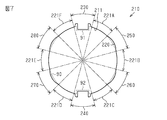
- the rotor core 210 of the second embodiment will be described with reference to FIG. 7.
- the rotor core 210 of the second embodiment is different from the rotor core 10 of the first embodiment in that the rotor core 210 of the second embodiment has six contact regions in which the shaft 90 and the inner wall 220 come into contact with each other when the shaft 90 is inserted into the shaft hole 211.
- a first key region 230 is provided in the shaft hole 211 of the rotor core 210.
- a key to be inserted into the first key groove 91 of the shaft 90 is arranged.
- the shaft hole 211 is provided with a second key region 240.
- a key to be inserted into the second key groove 92 of the shaft 90 is arranged.
- the portions on both sides adjacent to the first key region 230 in the circumferential direction of the shaft hole 211 are contact regions.
- the portions on both sides adjacent to the second key region 240 in the circumferential direction are also contact regions. Further, in the rotor core 210, the intermediate position sandwiched between the first key region 230 and the second key region 240 is the contact region.
- the contact area adjacent to the first key area 230 in the clockwise direction is defined as the first contact area 221A.
- the six contact areas are arranged in the clockwise direction with respect to the first contact area 221A in the order of the first contact area 221A, the second contact area 221B, the third contact area 221C, the fourth contact area 221D, and the fifth contact.
- the first contact area 221A to the sixth contact area 221F are arranged side by side at equal intervals.
- the first key area 230 is arranged at a position sandwiched between the sixth contact area 221F and the first contact area 221A.
- the second key region 240 is arranged at a position sandwiched between the third contact region 221C and the fourth contact region 221D.
- the rotor core 210 has six key areas and six diameter-expanded areas in total. That is, the rotor core 210 has four diameter-expanded regions.
- the diameter-expanded region sandwiched between the first contact region 221A and the second contact region 221B is referred to as the first diameter-expanded region 250.
- the diameter-expanded region sandwiched between the second contact region 221B and the third contact region 221C is referred to as the second diameter-expanded region 260.
- the diameter-expanded region sandwiched between the fourth contact region 221D and the fifth contact region 221E is referred to as the third diameter-expanded region 270.
- the expanded diameter region sandwiched between the fifth contact region 221E and the sixth contact region 221F is referred to as the fourth enlarged diameter region 280.
- the second contact region 221B is sandwiched between the first diameter expansion region 250 and the second diameter expansion region 260.
- the fifth contact region 221E is sandwiched between the third diameter expansion region 270 and the fourth diameter expansion region 280.
- the length of the inner wall 220 in the first contact area 221A is equal to the length of each inner wall 220 in the second contact area 221B to the sixth contact area 221F.
- the width of the first contact region 221A is the same as the width of each of the second contact regions 221B to the sixth contact region 221F.
- the length of the inner wall 220 in the first enlarged diameter region 250 is equal to the length of each inner wall 220 in the second expanded diameter region 260 to the fourth expanded diameter region 280.
- the width of the first enlarged diameter region 250 is the same as the width of each of the second expanded diameter region 260 to the fourth expanded diameter region 280. Further, the width of the first enlarged diameter region 250 is the same as the width of the first key region 230 and the width of the second key region 240.
- the shaft hole 211 of the rotor core 210 is provided with six contact regions, but unlike the case of the comparative example shown in FIG. 5, the six contact regions are arranged at equal intervals. As a result, when the shaft 90 is inserted into the shaft hole 211, the distortion of the shaft hole 211 tends to be uniform. A regular hexagon is formed by connecting the points where the pressing force acts on the six contact areas arranged at equal intervals.
- contact regions having the same width can be arranged at equal intervals, such as the rotor core 210, the same effects as (1-1) to (1-3) of the first embodiment can be obtained.
- connection path connecting the oil passage and the shaft hole is arranged as in the rotor core 10 of the first embodiment, it is preferable to connect the connection path to a region where the radius distance is larger than the radius of the shaft 90. As a result, the same effect as that of (1-4) of the first embodiment can be obtained.
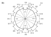
- the number of contact areas in the shaft hole of the rotor core can be changed. For example, as shown in FIG. 8, eight contact areas may be arranged side by side at equal intervals.
- the rotor core 310 shown in FIG. 8 includes a first key region 330. In the first key region 330, a key inserted into the first key groove 91 of the shaft 90 is arranged.
- the rotor core 310 includes a second key region 340. In the second key region 340, a key inserted into the second key groove 92 of the shaft 90 is arranged.
- the rotor core 310 includes eight key regions and eight diameter expansion regions in total. That is, six diameter-expanded regions are arranged in the shaft hole 311 of the rotor core 310.
- the inner wall 320 of the shaft hole 311 of the rotor core 310 clockwise from the first key region 330, the first key region 330, the first contact region 321A, the first enlarged diameter region 350, the second contact region 321B, and the second expanded diameter.
- the area 360, the third contact area 321C, the third enlarged diameter area 370, the fourth contact area 321D, and the second key area 340 are arranged side by side in this order.
- the first contact regions 321A to the eighth contact regions 321H are arranged side by side at equal intervals.
- the length of the inner wall 320 in the first contact region 321A is equal to the length of each inner wall 320 in the second contact region 321B to the eighth contact region 321H.
- the width of the first contact region 321A is the same as the width of each of the second contact regions 321B to the eighth contact region 321H.
- the distortion of the shaft hole 311 tends to be uniform when the shaft 90 is inserted into the shaft hole 311 as in each of the above embodiments.
- a regular octagon is formed by connecting the points where the pressing force acts on the eight contact areas arranged at equal intervals.
- the amount of deformation tends to be small.
- the smaller the width of the enlarged diameter region in which the contact regions are adjacent to both sides in the circumferential direction the smaller the amount of deformation when the inner wall in the enlarged diameter region is deformed radially inward is likely to be small.
- the distance between the contact areas can be narrowed.
- the R shape may be adjacent to the key. That is, the key area may be composed of a key and two R shapes sandwiching the key.
- the shape of the shaft hole is the same at all positions from one opening end of the shaft hole to the other opening end, but such a configuration is not essential.
- the radial distances in the region excluding the key region may be equal.
- the radius distance in the region excluding the key region may be larger than the radius of the shaft 90, or may be a size in contact with the shaft 90 inserted into the shaft hole.
- the shaft 90 is fixed to the rotor core by press-fitting the shaft 90 into the shaft hole.
- the method of fixing the shaft 90 is not limited to press fitting.
- the shaft 90 can be fixed to the rotor core by shrink fitting.
- the shaft 90 can be fixed to the rotor core by diffusion joining. Even if the shaft 90 is not fixed by press fitting, when the shaft 90 is inserted into the shaft hole and the shaft 90 is fixed, a pressing force may be generated when the shaft 90 comes into contact with the inner wall of the shaft hole, and the shaft hole may be deformed. be.
- the shaft hole is deformed even when the shaft 90 is fixed to the rotor core by a method other than press fitting. Can be even.
- the shaft hole may have one key or three or more keys. ..
- the two keys formed in the shaft hole are arranged at opposite positions.
- the keys provided in the shaft holes do not necessarily have to face each other.
- the shaft hole is provided with three or more contact regions, the widths of the contact regions are all the same, and the contact regions are arranged side by side at equal intervals, the entire shaft hole is provided as in each of the above embodiments. Is likely to be deformed evenly. For example, if the key area and the enlarged diameter area are three in total, the contact area sandwiched between the key area or the enlarged diameter area is three.
Landscapes
- Engineering & Computer Science (AREA)
- Power Engineering (AREA)
- Iron Core Of Rotating Electric Machines (AREA)
Abstract
Priority Applications (4)
| Application Number | Priority Date | Filing Date | Title |
|---|---|---|---|
| US18/003,581 US12316167B2 (en) | 2020-07-02 | 2021-07-01 | Rotor core |
| EP21832300.4A EP4178083A4 (fr) | 2020-07-02 | 2021-07-01 | Noyau de rotor |
| CN202180045447.9A CN115803990A (zh) | 2020-07-02 | 2021-07-01 | 转子铁芯 |
| JP2022534107A JP7477610B2 (ja) | 2020-07-02 | 2021-07-01 | ロータコア |
Applications Claiming Priority (2)
| Application Number | Priority Date | Filing Date | Title |
|---|---|---|---|
| JP2020114885 | 2020-07-02 | ||
| JP2020-114885 | 2020-07-02 |
Publications (1)
| Publication Number | Publication Date |
|---|---|
| WO2022004834A1 true WO2022004834A1 (fr) | 2022-01-06 |
Family
ID=79316360
Family Applications (1)
| Application Number | Title | Priority Date | Filing Date |
|---|---|---|---|
| PCT/JP2021/024889 Ceased WO2022004834A1 (fr) | 2020-07-02 | 2021-07-01 | Noyau de rotor |
Country Status (5)
| Country | Link |
|---|---|
| US (1) | US12316167B2 (fr) |
| EP (1) | EP4178083A4 (fr) |
| JP (1) | JP7477610B2 (fr) |
| CN (1) | CN115803990A (fr) |
| WO (1) | WO2022004834A1 (fr) |
Cited By (1)
| Publication number | Priority date | Publication date | Assignee | Title |
|---|---|---|---|---|
| JP2024058697A (ja) * | 2022-10-17 | 2024-04-30 | トヨタ自動車株式会社 | ロータコア |
Citations (4)
| Publication number | Priority date | Publication date | Assignee | Title |
|---|---|---|---|---|
| JP2010119270A (ja) * | 2008-11-14 | 2010-05-27 | Toyota Motor Corp | ロータおよび回転電機 |
| JP2013099222A (ja) | 2011-11-07 | 2013-05-20 | Toyota Motor Corp | ロータおよび回転電機 |
| JP2013143793A (ja) * | 2012-01-07 | 2013-07-22 | Mitsui High Tec Inc | 回転子鉄心及びその製造方法 |
| JP5469759B1 (ja) * | 2013-03-04 | 2014-04-16 | 株式会社三井ハイテック | 回転子鉄心及びその製造方法 |
Family Cites Families (7)
| Publication number | Priority date | Publication date | Assignee | Title |
|---|---|---|---|---|
| JP2008312321A (ja) * | 2007-06-13 | 2008-12-25 | Toyota Motor Corp | 回転子および回転電機 |
| US9065318B2 (en) * | 2013-03-14 | 2015-06-23 | Mitsui High-Tec, Inc. | Rotor core and method of manufacturing the same |
| JP5991545B2 (ja) * | 2013-11-15 | 2016-09-14 | 株式会社デンソー | 回転電機のロータ及びそのロータを備えた回転電機 |
| JP2015220846A (ja) * | 2014-05-16 | 2015-12-07 | トヨタ自動車株式会社 | 回転電機の回転子 |
| US10491062B2 (en) * | 2016-03-09 | 2019-11-26 | Ford Global Technologies, Llc | Electric machine rotor |
| JPWO2019123952A1 (ja) * | 2017-12-18 | 2020-12-03 | 日本電産株式会社 | ロータおよびモータ |
| CN110661349A (zh) * | 2018-06-29 | 2020-01-07 | 长城汽车股份有限公司 | 硅钢片和永磁电机 |
-
2021
- 2021-07-01 EP EP21832300.4A patent/EP4178083A4/fr active Pending
- 2021-07-01 CN CN202180045447.9A patent/CN115803990A/zh active Pending
- 2021-07-01 JP JP2022534107A patent/JP7477610B2/ja active Active
- 2021-07-01 WO PCT/JP2021/024889 patent/WO2022004834A1/fr not_active Ceased
- 2021-07-01 US US18/003,581 patent/US12316167B2/en active Active
Patent Citations (4)
| Publication number | Priority date | Publication date | Assignee | Title |
|---|---|---|---|---|
| JP2010119270A (ja) * | 2008-11-14 | 2010-05-27 | Toyota Motor Corp | ロータおよび回転電機 |
| JP2013099222A (ja) | 2011-11-07 | 2013-05-20 | Toyota Motor Corp | ロータおよび回転電機 |
| JP2013143793A (ja) * | 2012-01-07 | 2013-07-22 | Mitsui High Tec Inc | 回転子鉄心及びその製造方法 |
| JP5469759B1 (ja) * | 2013-03-04 | 2014-04-16 | 株式会社三井ハイテック | 回転子鉄心及びその製造方法 |
Non-Patent Citations (1)
| Title |
|---|
| See also references of EP4178083A4 |
Cited By (2)
| Publication number | Priority date | Publication date | Assignee | Title |
|---|---|---|---|---|
| JP2024058697A (ja) * | 2022-10-17 | 2024-04-30 | トヨタ自動車株式会社 | ロータコア |
| JP7740195B2 (ja) | 2022-10-17 | 2025-09-17 | トヨタ自動車株式会社 | ロータコア |
Also Published As
| Publication number | Publication date |
|---|---|
| JPWO2022004834A1 (fr) | 2022-01-06 |
| JP7477610B2 (ja) | 2024-05-01 |
| EP4178083A4 (fr) | 2023-12-27 |
| US20230318378A1 (en) | 2023-10-05 |
| EP4178083A1 (fr) | 2023-05-10 |
| US12316167B2 (en) | 2025-05-27 |
| CN115803990A (zh) | 2023-03-14 |
Similar Documents
| Publication | Publication Date | Title |
|---|---|---|
| CN103219812B (zh) | 具有分割式铁芯的电动机的转子及其制造方法 | |
| JP5990475B2 (ja) | 回転電機のロータ | |
| US11233433B2 (en) | Rotor and motor | |
| JP5299516B2 (ja) | モータのロータの製造方法 | |
| KR20090041300A (ko) | 회전 전기기계의 회전자, 및 그 제조 방법 | |
| CN103891106B (zh) | 旋转电机用转子及电动动力转向装置用电动机 | |
| CN104956569A (zh) | 旋转电机的转子及其制造方法 | |
| WO2022004834A1 (fr) | Noyau de rotor | |
| JP2018153047A (ja) | 回転電機のロータ | |
| JP2024102866A (ja) | ロータ | |
| US10826341B2 (en) | Rotor of motor apparatus | |
| JP5924706B2 (ja) | 回転電機の回転子構造 | |
| CN217720856U (zh) | 转子铁芯和电机 | |
| TWI715194B (zh) | 旋轉電機及其製造方法 | |
| JP7030140B2 (ja) | 回転電機、固定子 | |
| JP2018023232A (ja) | 回転電機および回転電機の製造方法 | |
| TWI495228B (zh) | 磁鐵埋設型轉子 | |
| CN109980814B (zh) | 内置式永磁电机转子和永磁电机 | |
| US11831205B2 (en) | Rotating electric machine and rotor therefor | |
| WO2026044513A1 (fr) | Noyau de rotor et rotor de moteur | |
| JP2014147227A (ja) | 回転電機の回転子およびその製造方法 | |
| JP2016220412A (ja) | 界磁用コアおよび界磁の製造方法 | |
| JP7752916B2 (ja) | モーターコアとシャフトとの嵌合構造 | |
| CN222052724U (zh) | 一种磁极组件、轴向磁通电机转子及轴向磁通电机 | |
| CN118889733B (zh) | 一种异步起动永磁同步电机转子隔磁桥、电机转子及电机 |
Legal Events
| Date | Code | Title | Description |
|---|---|---|---|
| 121 | Ep: the epo has been informed by wipo that ep was designated in this application |
Ref document number: 21832300 Country of ref document: EP Kind code of ref document: A1 |
|
| ENP | Entry into the national phase |
Ref document number: 2022534107 Country of ref document: JP Kind code of ref document: A |
|
| WWE | Wipo information: entry into national phase |
Ref document number: 2021832300 Country of ref document: EP |
|
| ENP | Entry into the national phase |
Ref document number: 2021832300 Country of ref document: EP Effective date: 20230202 |
|
| NENP | Non-entry into the national phase |
Ref country code: DE |
|
| WWG | Wipo information: grant in national office |
Ref document number: 18003581 Country of ref document: US |