WO2022009901A1 - 手術器械、医療器具セット、及び移植方法 - Google Patents
手術器械、医療器具セット、及び移植方法 Download PDFInfo
- Publication number
- WO2022009901A1 WO2022009901A1 PCT/JP2021/025519 JP2021025519W WO2022009901A1 WO 2022009901 A1 WO2022009901 A1 WO 2022009901A1 JP 2021025519 W JP2021025519 W JP 2021025519W WO 2022009901 A1 WO2022009901 A1 WO 2022009901A1
- Authority
- WO
- WIPO (PCT)
- Prior art keywords
- wire
- sleeve
- coracoid process
- spiral
- portal
- Prior art date
- Legal status (The legal status is an assumption and is not a legal conclusion. Google has not performed a legal analysis and makes no representation as to the accuracy of the status listed.)
- Ceased
Links
Images


Classifications
-
- A—HUMAN NECESSITIES
- A61—MEDICAL OR VETERINARY SCIENCE; HYGIENE
- A61B—DIAGNOSIS; SURGERY; IDENTIFICATION
- A61B17/00—Surgical instruments, devices or methods
- A61B17/56—Surgical instruments or methods for treatment of bones or joints; Devices specially adapted therefor
- A61B17/58—Surgical instruments or methods for treatment of bones or joints; Devices specially adapted therefor for osteosynthesis, e.g. bone plates, screws or setting implements
- A61B17/88—Osteosynthesis instruments; Methods or means for implanting or extracting internal or external fixation devices
-
- A—HUMAN NECESSITIES
- A61—MEDICAL OR VETERINARY SCIENCE; HYGIENE
- A61B—DIAGNOSIS; SURGERY; IDENTIFICATION
- A61B17/00—Surgical instruments, devices or methods
- A61B17/16—Instruments for performing osteoclasis; Drills or chisels for bones; Trepans
- A61B17/1662—Instruments for performing osteoclasis; Drills or chisels for bones; Trepans for particular parts of the body
- A61B17/1684—Instruments for performing osteoclasis; Drills or chisels for bones; Trepans for particular parts of the body for the shoulder
-
- A—HUMAN NECESSITIES
- A61—MEDICAL OR VETERINARY SCIENCE; HYGIENE
- A61B—DIAGNOSIS; SURGERY; IDENTIFICATION
- A61B17/00—Surgical instruments, devices or methods
- A61B17/16—Instruments for performing osteoclasis; Drills or chisels for bones; Trepans
- A61B17/17—Guides or aligning means for drills, mills, pins or wires
- A61B17/1739—Guides or aligning means for drills, mills, pins or wires specially adapted for particular parts of the body
- A61B17/1778—Guides or aligning means for drills, mills, pins or wires specially adapted for particular parts of the body for the shoulder
-
- A—HUMAN NECESSITIES
- A61—MEDICAL OR VETERINARY SCIENCE; HYGIENE
- A61B—DIAGNOSIS; SURGERY; IDENTIFICATION
- A61B17/00—Surgical instruments, devices or methods
- A61B17/56—Surgical instruments or methods for treatment of bones or joints; Devices specially adapted therefor
- A61B17/58—Surgical instruments or methods for treatment of bones or joints; Devices specially adapted therefor for osteosynthesis, e.g. bone plates, screws or setting implements
- A61B17/88—Osteosynthesis instruments; Methods or means for implanting or extracting internal or external fixation devices
- A61B17/8866—Osteosynthesis instruments; Methods or means for implanting or extracting internal or external fixation devices for gripping or pushing bones, e.g. approximators
-
- A—HUMAN NECESSITIES
- A61—MEDICAL OR VETERINARY SCIENCE; HYGIENE
- A61B—DIAGNOSIS; SURGERY; IDENTIFICATION
- A61B17/00—Surgical instruments, devices or methods
- A61B17/16—Instruments for performing osteoclasis; Drills or chisels for bones; Trepans
- A61B17/1604—Chisels; Rongeurs; Punches; Stamps
-
- A—HUMAN NECESSITIES
- A61—MEDICAL OR VETERINARY SCIENCE; HYGIENE
- A61B—DIAGNOSIS; SURGERY; IDENTIFICATION
- A61B17/00—Surgical instruments, devices or methods
- A61B17/16—Instruments for performing osteoclasis; Drills or chisels for bones; Trepans
- A61B17/1659—Surgical rasps, files, planes, or scrapers
-
- A—HUMAN NECESSITIES
- A61—MEDICAL OR VETERINARY SCIENCE; HYGIENE
- A61B—DIAGNOSIS; SURGERY; IDENTIFICATION
- A61B17/00—Surgical instruments, devices or methods
- A61B17/56—Surgical instruments or methods for treatment of bones or joints; Devices specially adapted therefor
- A61B17/58—Surgical instruments or methods for treatment of bones or joints; Devices specially adapted therefor for osteosynthesis, e.g. bone plates, screws or setting implements
- A61B17/68—Internal fixation devices, including fasteners and spinal fixators, even if a part thereof projects from the skin
- A61B17/84—Fasteners therefor or fasteners being internal fixation devices
- A61B17/86—Pins or screws or threaded wires; nuts therefor
- A61B17/864—Pins or screws or threaded wires; nuts therefor hollow, e.g. with socket or cannulated
-
- A—HUMAN NECESSITIES
- A61—MEDICAL OR VETERINARY SCIENCE; HYGIENE
- A61B—DIAGNOSIS; SURGERY; IDENTIFICATION
- A61B17/00—Surgical instruments, devices or methods
- A61B17/56—Surgical instruments or methods for treatment of bones or joints; Devices specially adapted therefor
- A61B17/58—Surgical instruments or methods for treatment of bones or joints; Devices specially adapted therefor for osteosynthesis, e.g. bone plates, screws or setting implements
- A61B17/88—Osteosynthesis instruments; Methods or means for implanting or extracting internal or external fixation devices
- A61B17/8897—Guide wires or guide pins
-
- A—HUMAN NECESSITIES
- A61—MEDICAL OR VETERINARY SCIENCE; HYGIENE
- A61B—DIAGNOSIS; SURGERY; IDENTIFICATION
- A61B17/00—Surgical instruments, devices or methods
- A61B17/56—Surgical instruments or methods for treatment of bones or joints; Devices specially adapted therefor
- A61B2017/564—Methods for bone or joint treatment
Definitions
- the present invention relates to a surgical instrument used for transplanting a coracoid process to the scapula neck, a medical instrument set equipped with the surgical instrument, and a method of transplanting the coracoid process to the scapula neck.
- a coracoid process an operation of transplanting the coracoid process of the scapula to the neck of the scapula (hereinafter referred to as a coracoid process) has been performed. If the coracoid process is performed under direct vision, there is a risk of muscle invasion and postoperative joint contracture, and if these symptoms occur in athletes, it will be difficult to return to competition. It was.
- arthroscopic coracoid process transfer is useful, and as this arthroscopic coracoid process, the transfer technique disclosed in Non-Patent Document 1 is known. There is. In this transition technique, the following steps A to G are carried out.
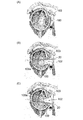
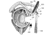
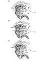
- Step A As shown in FIG. 32, the incision 102 is formed in the subscapularis 100 by moving the switching stick 101 penetrating the subscapularis 100 in the vertical direction (FIG. 32 (FIG. 32).
- A) shows a state before the switching stick 101 penetrates the subscapularis muscle 100
- FIG. 32B shows a state in which the switching stick 101 penetrating the subscapularis muscle 100 is tilted upward.
- FIG. 32 (C) shows a state in which the switching stick 101 penetrating the subscapularis muscle 100 is tilted downward).
- Step B As shown in FIGS.
- the guide wire 105 is inserted into the body from the first portal 104 formed on the skin at a position directly above the coracoid process 103, and the guide wire 105 is inserted into the body. Is pierced into the coracoid process 103, and then the hollow spiral 106 is moved toward the coracoid process 103 along the guide wire 105 while the guide wire 105 is passed through the cavity of the hollow spiral 106, and is hollow in the coracoid process 103. The spiral 106 is screwed in, and then the guide wire 105 is pulled out of the body from the first portal 104 (FIG.
- Step C As shown in FIG. 34, the coracoid process 103 is cut from the scapula 108 by the bone flea 107 inserted from the first portal 104 (at this time, the coracoid process 103 with the joint tendon 109 still attached). In this state, the coracoid process 103 is cut).
- Step D As shown in FIGS.
- Step E As shown in FIGS. 36 (A) and 36 (B), the coracoid process 103 is removed from the forceps 110, and the coracoid process 103 is suspended in the body fluid, and the skin in front of the incision 102 is formed.
- a plastic cylinder 112 is inserted into the body from the second portal 111 formed at the position, and the head of the spiral 106 is inserted into the opening 113 at the tip of the cylinder 112.
- Step F As shown in FIG. 37 (A), by advancing the tubular body 112, the coracoid process 103 is inserted into the incision 102 and brought into the vicinity of the scapula neck 108a.
- Step G As shown in FIG. 37 (A), a long spiral 113 that has passed through the cavity 112a of the tubular body 112 is passed through the cavity of the spiral 106 and screwed into the coracoid process 103, and then the second step.
- the tubular body 112 is pulled out of the body from the portal 111 (FIG. 37 (B) shows a state after the tubular body 112 is pulled out of the body).
- step E the coracoid process 103 floating in the body fluid with the tubular body 112 in step E (FIG. 36) (the coracoid process 103 floats in the body fluid). It was very difficult to insert the head of the spiral 106 into the opening 113 of the tubular body 112). Therefore, in the conventional coracoid process, it takes a long time to bring the coracoid process 103 close to the scapular neck 108a. In addition, because the above step E is extremely difficult, the work under the arthroscope may be abandoned and the work may be changed to the work under the arthroscope.
- the neurovascular system 200 in the vicinity of the shoulder joint is moved back and forth by the subscapularis muscle 100 and the joint tendon 109. It is sandwiched in the direction (the above-mentioned neurovascular system 200 includes a myocutaneous nerve 200a, an axillary nerve 200b, a subscapularis artery 200c, and the like). And if this pinch is tight, complications may occur due to damage to the neurovascular system 200. For example, if the musculocutaneous nerve 200a is damaged due to the tight pinching, a complication that the elbow does not bend may occur. Further, when the axillary nerve 200b is paralyzed due to the tight pinching, a complication that the shoulder cannot be raised may occur.
- the present invention has been made in view of the above matters, and an object of the present invention is a surgical instrument capable of easily realizing a coracoid process close to the scapular neck, and a medical device provided with the surgical instrument. It is to provide a set of equipment. Another object of the present invention is to provide a method for transplanting a coracoid process, which allows the coracoid process to be brought close to the scapular neck without damaging the neurovascular system.
- the present invention includes the subjects described in the following sections.
- Item 1 A surgical instrument used to transplant the coracoid process into the neck of the scapula. With a handle that extends in the first direction, With an inclined portion extending in the second direction from the tip of the handle, The second direction in which the inclined portion extends is inclined at an angle of 95 ° or more and 115 ° or less with respect to the first direction in which the handle extends. A surgical instrument in which a notch through which a spiral is passed is formed on the outer edge of the inclined portion.
- Item 2 The surgical instrument according to Item 1, wherein a through hole through which a spiral is passed is formed in the inclined portion.
- Item 3 The surgical instrument according to Item 2, wherein an outwardly projecting protrusion is formed at a lateral position of the through hole in the inclined portion.
- the handle has a grip portion, which is a handle, connected to the base end side of the handle body.
- the inclined portion extends from the tip of the handle body in the second direction.
- Item 6. The surgical instrument according to any one of Items 1 to 3, wherein the length of the range of the handle body between the grip portion and the inclined portion is 8 cm or more and 12 cm or less.
- the surgical instrument according to Item 4 and Including cutting tools used to cut the coracoid process The cutting tool is a series of a thick portion used as a handle and a thin portion having a thickness thinner than the thick portion, and the tip of the thin portion farthest from the thick portion is formed. It is said to be the thinnest cutting edge, A medical device set in which the length of the thin portion is 6 cm or more and 8 cm or less.
- Item 6 The surgical instrument according to any one of Items 1 to 4 and With the first wire, With the second wire, With the third wire, A medical device set that includes a first sleeve
- the first wire, the second wire, the third wire, and the first sleeve can each be passed through the notch of the surgical instrument.
- the first wire is a hollow cylinder, and the third wire can be inserted into the cavity of the first wire, and a groove extending spirally on the outer peripheral surface of the tip end portion of the first wire. Is formed,
- the tip of the second wire has a rounded shape.
- the tip of the third wire is tapered with corners.
- the first sleeve is a hollow tubular body, and a medical device set capable of inserting the first wire, the second wire, and the third wire into the cavity of the first sleeve. ..
- Item 7 The surgical instrument according to any one of Items 1 to 4 and Polishing tools and With the second sleeve, With the third sleeve, With the fourth sleeve With the 4th wire
- a medical device set that includes a fifth wire The second sleeve, the third sleeve, the fourth sleeve, and the polishing tool are hollow cylinders, respectively. Inserting the third sleeve into the cavity of the second sleeve, inserting the fourth sleeve into the cavity of the third sleeve, and inserting the fourth wire or the fifth wire into the cavity of the fourth sleeve. And it is possible to insert the polishing tool into the cavity of the second sleeve.
- the fourth wire can be inserted into the cavity of the polishing tool and the cavity of the fourth sleeve, and the tip of the fourth wire has a rounded shape.
- the fifth wire can be inserted through the cavity of the polishing tool, the cavity of the fourth sleeve, and the notch of the surgical instrument, and the tip of the fifth wire is tapered with a corner.
- the polishing tool With the base end of the polishing tool connected to the power tool, the polishing tool can be rotated around the central axis by operating the power tool, and the tip surface of the polishing tool is placed on the shoulder.
- a medical device set capable of polishing the surface of the scapula neck with the tip surface of the polishing tool by rotating the polishing tool in contact with the surface of the scapula neck.
- Item 8 The medical device set according to Item 7, wherein the tip of the third sleeve and the tip of the fourth sleeve each exhibit a tapered shape.
- Item 9 A method of transplanting the coracoid process into the scapular neck using the surgical instrument according to any one of Items 1 to 4.
- a spiral inserted into the body from the first portal is passed through a notch in the inclined portion and screwed into the coracoid process, whereby the inclined portion is fastened to the coracoid process by the one spiral.
- the screw of the one spiral into the coracoid process is released, and the one spiral is taken out of the body from the second portal formed on the skin at the position in front of the incision, and from the one spiral.
- the sixth step in which a long two spiral is inserted into the body from the second portal, passed through the notch, and screwed into the coracoid process and the scapula neck.
- a method comprising a seventh step of removing the surgical instrument from the two spirals by moving the surgical instrument and taking the surgical instrument out of the body from the first portal.
- one guide wire inserted into the body from the first portal is passed through the notch of the inclined portion and pierced into the coracoid process, and then the one is inserted into the one spiral cavity. With the guide wire passed, the one spiral is moved toward the notch along the one guide wire, and the one helix is passed through the notch and screwed into the coracoid process. After that, the one guide wire is pulled out of the body from the first portal.
- the second guide wire is inserted into the body from the second portal, the second guide wire is passed through the cavity of the first spiral, and the scapula neck is pierced, and then the second guide wire is pierced.
- the one spiral is unscrewed into the coracoid process, and the one spiral is moved along the two guide wires to be taken out of the body from the second portal, and then the one.
- the second guide wire passed through the cavity of the second spiral, which is longer than the second spiral, the second spiral is moved toward the notch along the second guide wire.
- Item 9 The item 9 in which the spiral is screwed into the coracoid process and the scapula neck through the notch, and then the second guide wire is pulled out of the body from the second portal.
- the surgical instrument is the surgical instrument according to Item 2 or 3. Further having an eighth step carried out after the seventh step, In the third step, the three spirals inserted into the body from the first portal are passed through the through hole and screwed into the coracoid process, whereby the inclined portion is made into the coracoid process by the three spirals. It is done to conclude, In the sixth step, the screwing of the three spirals into the coracoid process is released, and the three spirals are taken out of the body from the second portal. In the eighth step, four spirals longer than the three spirals are inserted into the body from the second portal, and the four spirals are screwed into the coracoid process. Item 9. The method according to Item 9 or 10, wherein the screw is passed through the hole of the protrusion and screwed into the coracoid process and the scapular neck.
- the three guide wires inserted into the body from the first portal are passed through the through hole and pierced into the coracoid process, and then the three guide wires are inserted into the three spiral cavities.
- the three spirals are moved toward the through hole along the three guide wires, and the three spirals are passed through the through hole and screwed into the coracoid process, and then , The three guide wires are pulled out of the body from the first portal.
- the four guide wires are inserted into the body from the second portal, the four guide wires are passed through the cavity of the three spirals, and the scapula neck is pierced, and then the scapula neck is pierced.
- the three spirals are unscrewed into the coracoid process, and the three spirals are moved along the four guide wires to be taken out of the body from the second portal and the four guides.
- the wire is pulled out of the body from the second portal.
- the five guide wires are inserted into the body from the second portal, and the five guide wires are inserted into the hole of the coracoid process into which the three spirals are screwed and the four.
- the guide wire was passed through the hole in the neck of the scapula where the guide wire was pierced, and then the guide wire of the five was passed through the cavity of the four spirals, which was longer than the three spirals.
- the inclined portion is inclined at an angle of 95 ° or more and 115 ° or less with respect to the handle body, so that the position directly above the coracoid process suitable for forming a portal.
- the slope can be brought into contact with the coracoid process attached to the scapula under the condition that the handle passes through. Then, if the inclined portion is brought into contact with the coracoid process in this way, the work of screwing the spiral into the coracoid process through the notch can be performed while the coracoid process is attached to the scapula and is stable. .. Therefore, it is possible to easily connect the inclined portion to the coracoid process using a spiral.
- the coracoid process can be brought closer to the scapula neck by a simple operation of moving the surgical instrument downward. can.
- the coracoid process can be easily brought close to the scapular neck.
- the joint tendon and the coracoid process move downward as the surgical instrument is moved downward in the fifth step to bring the coracoid process closer to the scapular neck.
- Pression of the tendon or coracoid process can move the neurovascular system in the vicinity of the scapula downward. This makes it possible to weaken the anterior-posterior (horizontal) neurovascular system pinch between the subscapularis muscle and the joint tendon, so that the coracoid process is closer to the scapular neck without damaging the neurovascular system. Can be made to. This avoids complications due to damage to the neurovascular system.
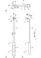
- FIG. 1 It is a perspective view (photograph) of the surgical instrument which concerns on embodiment of this invention.
- A is a plan view showing a state in which the surgical instrument is viewed from a direction perpendicular to the handle, and
- B is a plan view showing a state in which the surgical instrument is viewed from a direction perpendicular to the inclined portion.
- C is a side view of the surgical instrument. It is a schematic diagram which shows the procedure of the method of transplanting the coracoid process which concerns on embodiment of this invention. It is a schematic diagram which shows the procedure of the method of transplanting the coracoid process which concerns on embodiment of this invention.
- (A) is a plan view of the cutting tool
- (B) is a side view of the cutting tool.
- (A) is a side view of the first wire
- (B) is a side view of the second wire
- (C) is a side view of the third wire.
- It is a side view of the first sleeve.
- It is a schematic side view which shows the tip part of the 1st wire.
- It is a schematic side view which shows the tip part of the 2nd wire.
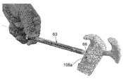
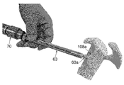
- FIG. 1 is a perspective view (photograph) showing a surgical instrument 1 according to an embodiment of the present invention.
- FIG. 2A is a plan view showing a state in which the surgical instrument 1 is viewed from a direction perpendicular to the handle 2 described later.
- FIG. 2B is a plan view showing a state in which the surgical instrument 1 is viewed from a direction perpendicular to the inclined portion 3 described later.
- FIG. 2C is a side view of the surgical instrument 1.
- 3 to 10 are schematic views showing a procedure of a method of transplanting a coracoid process 103 performed under arthroscopy using a surgical instrument 1.
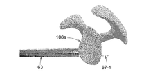
- the surgical instrument 1 (FIGS. 1 and 2) according to the present embodiment is used for transplanting the coracoid process 103 to the scapular neck 108a (specifically, the surgical instrument 1 has the coracoid process 103 on the shoulder. Used to spirally secure the coracoid process 103 to the scapular neck 108a in close proximity to the scapular neck 108a).
- the surgical instrument 1 includes a handle 2 extending in the first direction and an inclined portion 3 extending in the second direction from the tip of the handle 2.
- the second direction in which the inclined portion 3 extends is inclined at an angle ⁇ of 95 ° or more and 115 ° or less with respect to the first direction in which the handle 2 extends (see FIG. 2C for the angle ⁇ ).
- the handle 2 has a grip portion 5 as a handle connected to the base end side of the handle body 4.
- the grip portion 5 is a tubular body having an opening 6 (FIG. 2 (B)) at the tip (one end), and is formed of a stainless alloy, a titanium alloy, or an aluminum alloy.
- the length L1 (FIG. 1) of the grip portion 5 is set to, for example, 5 cm or more.
- the width H1 (FIG. 2A) of the grip portion 5 is, for example, 1 cm or more and 2 cm or less.
- the handle body 4 is a bar made of a stainless alloy, a titanium alloy, or an aluminum alloy.
- the cross section of the handle body 4 has a rectangular shape, and the dimensions (width, height) of the cross section of the grip portion 5 are larger than the dimensions (width, height) of the cross section of the handle body 4.
- the base end side of the handle body 4 grips the handle body 4 with the base end side of the handle body 4 inserted into the grip portion 5 from the opening 6 of the grip portion 5. It is performed by being fixed to the portion 5.
- the inclined portion 3 extends from the tip of the handle main body 4, and the length L2 (FIG.
- the width H2 (FIG. 2A) of the handle body 4 is, for example, 0.4 cm or more and 0.8 cm or less.
- the shape of the cross section of the handle body 4 may be a shape other than a rectangle (for example, the cross section of the handle body 4 may be circular or elliptical).
- the grip portion 5 may be connected to the base end side of the handle body 4 by a known method other than the above. Further, the grip portion 5 may be integrally molded with the handle body 4 so as to be connected to the base end side of the handle body 4. Also in this case, the dimensions (width, height) of the cross section of the grip portion 5 are larger than the dimensions (width, height) of the cross section of the handle body 4.
- the inclined portion 3 is a plate-shaped body extending in the second direction from the tip of the handle body 4.
- the inclined portion 3 is formed of a stainless alloy, a titanium alloy, or an aluminum alloy, and is integrally molded with the handle body 4.
- the length L3 (FIG. 1) of the inclined portion 3 is, for example, 1.5 cm or more and 2.5 cm or less, and the width H3 of the inclined portion 3 (FIG. 2 (B)) is, for example, 1.2 cm or more and 1.5 cm or less.
- the width H3 of the inclined portion 3 means the maximum width of the inclined portion 3).
- a notch 10 through which a spiral is passed is formed on the outer edge of the inclined portion 3 on the tip end side.
- the notch 10 opens outward, and is a spiral 21 screwed into the coracoid process 103 (FIGS. 5 to 8) and a spiral 26 screwed into the coracoid process 103 and the scapula neck 108a (FIG. 5 to 8). 8 to 10) are passed through the notch 10.
- the bifurcated portions 11 and 11 are formed on the tip end side of the inclined portion 3, and the notch 10 is formed by the space between the bifurcated portions 11 and 11, and the notch is formed.
- the cross section of 10 has a semicircular shape.
- a through hole 12 through which a spiral is passed is formed on the base end side (handle 2 side) of the inclined portion 3.
- the cross section of the through hole 12 has a circular shape, and the spiral 23 (FIGS. 5 to 8) screwed into the coracoid process 103 is passed through the through hole 12.
- a protruding portion 13 projecting outward is formed at a position on the side of the through hole 12 in the inclined portion 3 (the above-mentioned "lateral position of the through hole 12" is inclined with respect to the through hole 12. It means a position outside the width direction of the portion 3, and the above-mentioned "width direction of the inclined portion 3" means a direction orthogonal to the longitudinal direction of the inclined portion 3).
- the protrusion 13 is provided as a mark for grasping the position of the through hole 12 when the surgical instrument 1 is used.
- the shape of the notch 10 can be any shape having an opening through which the spirals 21 and 26 can be taken in and out.
- the shape of the through hole 12 may be any shape through which the spiral 23 can be passed.
- the above-mentioned spirals 21, 23, 26 have a small-diameter spiral portion extending from a large-diameter head, and the shape of the notch 10 is such that the spiral portions of the spirals 21 and 26 are taken in and out from the opening.
- the head of the spiral 21 and 26 abuts on the surface of the inclined portion 3 around the notch 10 in a state where the spiral portion of the spiral 21 and 26 is passed through the notch 10.
- the shape of the through hole 12 is such that the head of the spiral 23 can be brought into contact with the surface of the inclined portion 3 around the through hole 12 in a state where the spiral portion of the spiral 23 is passed through the through hole 12. It can be a shape.
- a notch 10 may be formed on the outer edge of the base end side (handle 2 side) of the inclined portion 3.
- a through hole 12 may be formed on the tip end side of the inclined portion 3.
- a plurality of notches 10 may be formed in the inclined portion 3, and a plurality of through holes 12 may be formed in the inclined portion 3.
- the through hole 12 and the protruding portion 13 are not always necessary and may not be formed on the inclined portion 3.
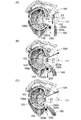
- the first step of forming an incision 102 in the subscapularis muscle 100 is carried out (FIG. 3).
- the incision 102 is formed in the subscapularis 100 by moving the switching stick 20 penetrating the subscapularis 100 in the vertical direction.
- FIG. 3 (A) shows a state before the switching stick 20 penetrates the subscapularis muscle 100
- FIG. 3 (B) shows a state in which the switching stick 20 is tilted upward
- FIG. 3 (C) shows the state. Indicates a state in which the switching stick 20 is tilted downward
- the incision 102 may be formed by a known method other than the above.
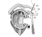
- the second step of inserting the surgical instrument 1 into the body from the first portal 104 formed on the skin at a position directly above the coracoid process 103 and bringing the inclined portion 3 into contact with the coracoid process 103. Is carried out. Specifically, when the user grips the grip portion 5 (FIGS. 1 and 2) and operates the surgical instrument 1, the handle body 4 and the tilted portion 3 are inserted into the body from the first portal 104 and tilted. The portion 3 is brought into contact with the coracoid process 103.
- the first portal 104 is formed at a position directly above the coracoid process 103 from the viewpoint of shortening the distance between the first portal 104 and the coracoid process 103 to reduce the burden on the patient.
- the through hole 12 is positioned.
- the through hole 12 is arranged at a desired position of the toriguchi protrusion 103 by using the protrusion 13 as a mark.
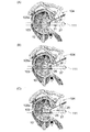
- a spiral 21 having a hollow structure is inserted into the body from the first portal 104, and the spiral 21 is passed through the notch 10 of the inclined portion 3 and screwed into the coracoid process 103, whereby the inclined portion 3 is formed by the spiral 21.
- the third step of fastening the screw to the coracoid process 103 is carried out (FIG. 5).
- the guide wire 22 inserted into the body from the first portal 104 is passed through the notch 10 and pierced into the coracoid process 103.
- the spiral 21 is moved toward the notch 10 along the guide wire 22, and the spiral 21 is passed through the notch 10 to pass the coracoid process 103.
- the guide wire 22 is then pulled out of the body from the first portal 104 (FIG. 5 (B) shows the state after the guide wire 22 is pulled out of the body).
- the spiral portion of the spiral 21 is passed through the notch 10 of the inclined portion 3 and screwed into the coracoid process 103, and is between the head of the spiral 21 and the coracoid process 103. By sandwiching the inclined portion 3, the inclined portion 3 is fastened to the coracoid process 103 by the spiral 21.
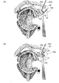
- the spiral 23 having a hollow structure from the first portal 104 (FIG. 5 (B). )) Is inserted into the body, the spiral 23 is passed through the through hole 12 of the inclined portion 3 and screwed into the coracoid process 103, so that the inclined portion 3 is fastened to the coracoid process 103 by the spiral 23. It is done.
- the guide wire 24 inserted into the body from the first portal 104 is passed through the through hole 12 and pierced into the coracoid process 103.
- the spiral 23 is moved toward the through hole 12 along the guide wire 24, and the spiral 23 is passed through the through hole 12 to pass the coracoid process 103.
- the guide wire 24 is then pulled out of the body from the first portal 104 (FIG. 5B shows a state immediately before the spiral 23 is passed through the through hole 12).
- the spiral portion of the spiral 23 is passed through the through hole 12 of the inclined portion 3 and screwed into the coracoid process 103, whereby the space between the head of the spiral 23 and the coracoid process 103 is performed.
- the inclined portion 3 is sandwiched between the two, and the inclined portion 3 is fastened to the coracoid process 103 by the spiral 23.
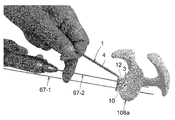
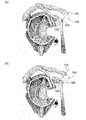
- the coracoid process 103 is attached to the coracoid process 103 with the joint tendon 109 by the bone flea 25 inserted from the first portal 104, and the coracoid process 103 is attached to the scapula 108.
- a fourth step of cutting from is carried out. At this time, the bone chisel 25 is inserted along the handle body 4 and the bone chisel 25 is inserted into the shoulder joint.
- the bone chisel 25 (the base end portion of the bone chisel 25) with a hammer while the bone chisel 25 is aligned with the handle body 4, the bone chisel 25 is slid along the handle body 4. , The coracoid process 103 is cut by the bone chisel 25.
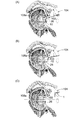
- FIGS. 7 (A), 7 (B), and 7 (C) by moving the surgical instrument 1 downward, the coracoid process 103 with the joint tendon 109 is moved downward. Then, the fifth step of inserting the coracoid process 103 into the incision 102 of the subscapularis muscle 100 and bringing it close to the scapular neck 108a is performed. At this time, the neurovascular system 200 in the vicinity of the shoulder joint also moves downward by pressing the joint tendon 109 or the coracoid process 103 that moves downward.
- the neurovascular system 200 includes a myocutaneous nerve 200a, an axillary nerve 200b, and a subclavian artery 200c, and FIG. 7 shows the myocutaneous nerve 200a, the axillary nerve 200b, and the subclavian artery by pressing the joint tendon 109. It shows a state in which the artery 200c moves downward.
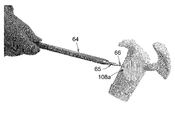
- a sixth step is performed in which a spiral 26 having a hollow structure is inserted into the body from the second portal 111, passed through the notch 10, and screwed into the coracoid process 103 and the scapula neck 108a (FIG. 8). ..
- the guide wire 27 inserted into the body from the second portal 111 is passed through the cavity of the spiral 21 and pierced into the scapula neck 108a.
- FIG. 8 shows the state when the spiral 21 is heading toward the second portal 111 along the guide wire 27, and FIGS. 8B and 8C show the spiral 21 taken out of the body. Shows the later state).
- the spiral 26 is moved toward the notch 10 along the guide wire 27, and the spiral 26 is passed through the notch 10 to pass the coracoid process.
- FIGS. 8A and 8B when the spiral 23 is screwed into the coracoid process 103, the spiral 23 is screwed into the coracoid process 103 in the sixth step. Is also released, and the spiral 23 is taken out of the body from the second portal 111.
- the guide wire 28 inserted into the body from the second portal 111 is passed through the cavity of the spiral 23 and pierced into the scapula neck 108a. Is done. After that, as shown in FIG.
- the spiral 23 is unscrewed into the coracoid process 103, and the spiral 23 is moved along the guide wire 28 to be moved from the second portal 111 to the outside of the body.
- the guide wire 28 is pulled out of the body from the second portal 111.
- the seventh step of removing the surgical instrument 1 from the spiral 26 and taking the surgical instrument 1 out of the body from the first portal 104 is performed.
- the surgical instrument 1 can be easily removed from the spiral 26 by having an opening in the notch 10 through which the spiral 26 is passed (that is, the spiral 26 has the notch 10 (bifurcated portions 11, 11).
- the surgical instrument 1 can be removed from the spiral 26 by performing a simple operation of moving the surgical instrument 1 so as to come out of the space).
- the coracoid process 103 is transplanted to the scapula neck 108a (the coracoid process 103 is fixed to the scapula neck 108a by the spiral 26).
- the guide wire 30 is inserted into the body from the second portal 111, and the hole of the coracoid process 103 into which the spiral 23 is screwed and the guide wire are inserted.
- the guide wire 30 (FIG. 10) is passed through the hole in the scapula neck 108a where 28 (FIG. 8) was pierced.
- the spiral 29 is moved along the guide wire 30 with the guide wire 30 passed through the cavity of the spiral 29, and the spiral 29 is formed into the above-mentioned coracoid process 103.
- the spirals 21 and 23 are screwed into the coracoid process 103
- the sixth step (FIG. 8) the screwing of the spirals 21 and 23 into the coracoid process 103 is released.
- the spirals 21 and 23 are taken out of the body, the spiral 26 is screwed into the coracoid process 103 and the scapula neck 108a in the sixth step (FIG. 8), and the spiral 29 is screwed into the coracoid process in the seventh step (FIG. 9). Screwing into the protrusion 103 and the scapula neck 108a can be achieved by using a known driver.
- the driver has, for example, a cavity through which a guide wire can be inserted, and by inserting the tip of the driver into the cavity of the spirals 21, 23, 26, 29, the tip of the driver has a spiral 21, 23, 26, It is possible to connect 29.
- the cavity of the driver is opened at the tip of the driver, and when the spirals 21, 23, 26, 29 are connected to the tip of the driver, the opening at the tip of the driver is the spiral 21, 23, 26.
- the spiral portion of the spiral is screwed into the coracoid process 103, or the spiral portion of the spiral is screwed into the coracoid process 103 and the scapula neck 108a. After that, by retracting the driver along the guide wire, the spiral is removed from the tip of the driver and the driver is taken out of the body.
- the driver when unscrewing the spirals 21 and 23 into the coracoid process 103 and taking out the spirals 21 and 23 outside the body, the driver is moved along the guide wire with the guide wire passed through the cavity of the driver. By inserting it into the body and inserting the tip of the driver into the cavity of the spiral, the spiral is connected to the tip of the driver. Then, by rotating the driver, the screwing of the spiral into the coracoid process 103 is released, and then, by retracting the driver and the spiral along the guide wire, the driver and the spiral are taken out of the body. ..
- the inclined portion 3 is inclined at an angle ⁇ (FIG. 2 (C)) of 95 ° or more and 115 ° or less with respect to the handle main body 4, which is shown in FIG.
- ⁇ FOG. 2 (C)
- the inclined portion 3 can be brought into contact with the coracoid process 103 under the condition that the handle 2 passes through the first portal 104 formed at a position directly above the coracoid process 103.
- the coracoid process 103 is stable because the coracoid process 103 is attached to the scapula 108 as shown in FIG.
- the spiral 21 can be passed through the notch 10 and screwed into the coracoid process 103. Therefore, the inclined portion 3 can be easily connected to the coracoid process 103 by using the spiral 21. Then, with the inclined portion 3 connected to the coracoid process 103 in this way, if the coracoid process 103 is cut from the scapula 108 as shown in FIG. 6, the surgical instrument 1 is moved downward as shown in FIG. The coracoid process 103 can be brought close to the scapular neck 108a by a simple operation. For the above reasons, according to the surgical instrument 1 of the present embodiment, the coracoid process 103 can be easily brought close to the scapula neck 108a.
- the joint tendon 109 and the coracoid process 103 are also moved downward.
- the neurovascular system 200 in the vicinity of the shoulder joint can be moved downward.
- the pinching of the neurovascular system 200 in the anterior-posterior direction (horizontal direction) by the subscapularis muscle 100 and the joint tendon 109 can be weakened, so that the neurovascular system 200 can be prevented from being damaged.
- the protruding portion 13 is formed at a position on the side of the through hole 12, the protruding portion 13 can be used as a mark for positioning the through hole 12. This makes it possible to easily arrange the through hole 12 at a desired position of the coracobrachial projection 103 in the second step (FIG. 4).
- a medical device set including the surgical instrument 1 shown in FIGS. 1 and 2 and the cutting tool 40 shown in FIG. 11 can be used.
- the cutting tool 40 can be used as a bone chisel 25 for cutting the coracoid process 103 in the fourth step shown in FIG.
- the cutting tool 40 (FIG. 11) is a series of a thick portion 41 used as a handle and a thin portion 42 having a thickness thinner than that of the thick portion 41.
- the tip 42a of the thin portion 42 farthest from the thick portion 41 is the thinnest cutting edge, and the length L4 of the thin portion 42 is 6 cm or more and 8 cm or less. If the cutting tool 40 is used as a bone chisel 25 (FIG. 6) for cutting the coracoid process 103, the length L4 (FIG.
- the handle body 4 can be suitably used as a guide for determining the cutting position of the coracoid process 103.
- the thin-walled portion 42 is formed so as to gradually widen and gradually become thinner as it is separated from the grip portion 5. Further, as shown in FIG. 11B, it is preferable that a warp is formed on the tip end side of the thin wall portion 42.
- the present invention does not require the use of the cutting tool 40, and a device other than the cutting tool 40 may be used as a bone chisel for cutting the coracoid process 103.
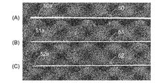
- the surgical instrument 1 shown in FIGS. 1 and 2 the first wire 50, the second wire 51, and the third wire 52 shown in FIG. 12 and FIG. 13
- a medical device set including the first sleeve 53 shown in the above can be used.
- the first wire 50, the second wire 51, the third wire 52, and the first sleeve 53 can be passed through the notch 10 and the through hole 12 of the surgical instrument 1, respectively.
- the first sleeve 53 shown in FIG. 13 is a hollow cylinder and is made of a stainless alloy, a titanium alloy, or an aluminum alloy.
- the outer diameter of the first sleeve 53 is, for example, 8 mm or less, and the inner diameter of the first sleeve 53 is, for example, 2 mm or less.
- the first sleeve 53 is used to guide the movement of the wires 50 and 51, and the wires 50, 51 and 52 can be inserted into the cavities of the first sleeve 53, respectively. ..
- the first wire 50 shown in FIG. 12A is a hollow tubular body and is formed of a stainless alloy, a titanium alloy, or an aluminum alloy.
- the outer diameter of the first wire 50 is, for example, 4 mm or less, and the inner diameter of the first wire 50 is, for example, 2 mm or less.
- a spirally extending groove 50a is formed on the outer peripheral surface of the tip of the first wire 50.
- the first wire 50 is used as, for example, the guide wires 22 and 24 shown in FIG. 5 and the guide wires 27 and 28 shown in FIG. 8 and is used as the first wire 50 (FIG. 12 (A)).
- the third wire 52 (FIG. 12 (C)) can be inserted through the cavity.
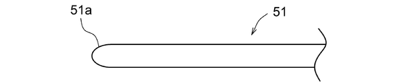
- the second wire 51 shown in FIG. 12B is formed of a stainless alloy, a titanium alloy, or an aluminum alloy, and the outer diameter of the second wire 51 is, for example, 2 mm or less. As shown in FIG. 14, the tip portion 51a of the second wire 51 has a rounded shape.
- the above-mentioned second wire 51 is used to guide the movement of the first sleeve 53.
- the second wire 51 can also be used as the guide wire 30 shown in FIG.
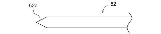
- the third wire 52 shown in FIG. 12C is made of a stainless alloy, a titanium alloy, or an aluminum alloy, and the outer diameter of the third wire 52 is, for example, 2 mm or less. As shown in FIG. 15, the tip portion 52a of the third wire 52 has a tapered shape with a corner.
- the third wire 52 is used to form a hole in the coracoid process 103 and the scapula neck 108a, and is formed in the coracoid process 103 and the scapula neck 108a by the third wire 52.
- the hole formed by the third wire 52 can be expanded in diameter to form a hole suitable for screwing the spiral.
- Work 1 Insert the second wire 51 (FIG. 12 (B)) from the first portal 104 (FIG. 5) into the body toward the coracoid process 103, and cut the tip of the second wire 51 into the notch of the inclined portion 3. Positioned at 10.
- Work 2 The first sleeve 53 is moved along the second wire 51 while the second wire 51 (FIG. 12 (B)) is passed through the cavity of the first sleeve 53 (FIG. 13). The sleeve 53 is inserted into the body and guided to the coracoid process 103, the tip of the first sleeve 53 is positioned at the notch 10, and then the second wire 51 is pulled out of the body from the first portal 104 (FIG. 5).
- the first wire 50 protruding from the tip of the first sleeve 53 is passed through the notch 10 and pierced into the coracoid process 103, thereby leading to the coracoid process 103.
- the hole of 103 is enlarged by the first wire 50 to form a hole suitable for screwing the spiral 21 into the coracoid process 103.
- Work 5 After the first sleeve 53 is pulled out of the body from the first portal 104 (FIG. 5), the spiral 21 is first placed in a state where the first wire 50 (corresponding to the guide wire 22) is passed through the cavity of the spiral 21.
- the following operations 6 to 10 are sequentially performed in order to realize a state in which the spiral 23 is passed through the through hole 12 of the inclined portion 3 and screwed into the coracoid process 103.
- Work 6 Insert the second wire 51 (FIG. 12 (B)) from the first portal 104 (FIG. 5) into the body toward the coracoid process 103, and insert the tip of the second wire 51 into the through hole of the inclined portion 3. Positioned at 12.
- Work 7 The first sleeve 53 is moved along the second wire 51 while the second wire 51 (FIG. 12 (B)) is passed through the cavity of the first sleeve 53 (FIG. 13). The sleeve 53 is inserted into the body and guided to the coracoid process 103, the tip of the first sleeve 53 is positioned in the through hole 12, and then the second wire 51 is pulled out of the body from the first portal 104 (FIG. 5).
- the first wire 50 protruding from the tip of the first sleeve 53 is passed through the through hole 12 and pierced into the coracoid process 103, thereby leading to the coracoid process 103.
- the hole of 103 is enlarged by the first wire 50 to form a hole suitable for screwing the spiral 23 into the coracoid process 103.
- Work 10 After pulling out the first sleeve 53 from the first portal 104 (FIG. 5), the first wire 50 (corresponding to the guide wire 24) is passed through the cavity of the spiral 23, and the spiral 23 is first placed.
- the spiral 23 is passed through the through hole 12 and screwed into the hole of the coracoid process 103 formed in the operation 9, and then the wires 50 and 52. Is pulled out of the body from the first portal 104.
- Work 11 The second wire 51 (FIG. 12 (B)) is inserted into the body from the second portal 111 (FIG. 8) toward the coracoid process 103, and the tip of the second wire 51 is spiraled 21 (FIG. 8 (FIG. 8). A) Position it in the cavity of).
- Work 12 The first sleeve 53 is moved along the second wire 51 while the second wire 51 (FIG. 12 (B)) is passed through the cavity of the first sleeve 53 (FIG. 13).
- the sleeve 53 is inserted into the body and guided to the coracoid process 103, the tip of the first sleeve 53 is positioned in the cavity of the spiral 21, and then the second wire 51 is pulled out of the body from the second portal 111 (FIG. 8). (Pull out the second wire 51 from the cavity of the first sleeve 53).
- Work 13 By passing the third wire 52 (FIG. 12 (C)) through the cavity of the first sleeve 53, the third wire 52 is inserted into the body and guided to the coracoid process 103, and from the tip of the first sleeve 53.
- the protruding third wire 52 is passed through the cavity of the spiral 21 (FIG.
- the first wire 50 (guide) is passed through the cavity of the first sleeve 53 while passing the first wire 50 (FIG. 12 (A)) through the cavity of the first wire 50 while passing the third wire 52. (Corresponding to the wire 27) is inserted into the body and guided to the coracoid process 103, and the first wire 50 protruding from the tip of the first sleeve 53 is passed through the cavity of the spiral 21 and pierced into the scapula neck 108a.
- the following operations 17 to 21 are sequentially performed in order to release the screwing of the spiral 23 into the coracoid process 103 and take out the spiral 23 from the body.
- Work 17 The second wire 51 (FIG. 12 (B)) is inserted into the body from the second portal 111 (FIG. 8) toward the coracoid process 103, and the tip of the second wire 51 is spiraled 23 (FIG. 8 (FIG. 8). A) Position it in the cavity of).
- Work 18 The first sleeve 53 is inserted into the body by moving the first sleeve 53 along the second wire 51 while passing the second wire 51 through the cavity of the first sleeve 53 (FIG. 13). The tip of the first sleeve 53 is positioned in the cavity of the spiral 23, and then the second wire 51 is pulled out of the body from the second portal 111 (FIG. 8) (the cavity of the first sleeve 53).
- the following operations 22 to 24 are sequentially performed in order to realize a state in which the spiral 29 is screwed into the coracoid process 103 and the scapula neck 108a.
- the second wire 51 (FIG. 12 (B)) is inserted into the body from the second portal 111 (FIG. 10) toward the coracoid process 103, and the spiral 23 (FIGS. 5 to 8) is screwed into the body.
- the second wire 51 is inserted into the hole of the coracoid process 103 and the hole of the scapula neck 108a formed in the work 20 (the hole of the scapula neck 108a in which the guide wire 28 shown in FIG. 8 is pierced). Pass through.
- Work 23 With the second wire 51 (corresponding to the guide wire 30) passed through the cavity of the spiral 29, the spiral 29 is moved along the second wire 51 toward the coracoid process 103, and the spiral 23 (FIG.
- the medical device set including surgical instrument 1 (FIGS. 1, 2), wires 50, 51, 52 (FIG. 12), and first sleeve 53 (FIG. 13), at work 3,8,13,19.
- the third wire 52 (FIG. 12 (C)) is passed through the cavity of the first sleeve 53 (FIG. 13), and in operations 4, 9, 14, 20 the first wire 50 (FIG. 12 (A)) is first.
- the wires 52 and 50 can be smoothly guided to the coracoid process 103 without damaging the inside of the body by the wires 52 and 50.
- the first sleeve 53 is smoothly guided to the coracoid process 103 by passing the second wire 51 (FIG. 12 (B)) through the cavity of the first sleeve 53 (FIG. 13). be able to.
- the tip portion 51a of the second wire 51 since the tip portion 51a of the second wire 51 has a rounded shape, the second wire 51 does not damage the inside of the body in the operations 1, 6, 11, 17, and 22. , The second wire 51 can be moved toward the coracoid process 103.
- the surface of the scapula neck 108a is polished before the fifth step (FIG. 7) of bringing the coracoid process closer to the scapula neck 108a to obtain the scapula.
- a flattening step may be performed to flatten the surface of the cervical portion 108a.
- the coracoid process 103 is attached to the scapula neck 108a so that the surface of the scapula neck 108a flattened in the flattening step and the surface of the coracoid process 103 are in contact with each other. Proximity is done.
- the surgical instrument 1 shown in FIGS. 1 and 2 and the polishing shown in FIGS. 16 and 17 are performed.
- a medical device set including a fourth wire 66 and a fifth wire 67 may be used.
- the second sleeve 63, the third sleeve 64, the fourth sleeve 65, and the polishing tool 60 are hollow cylinders, respectively, and the third sleeve 64 can be inserted into the cavity of the second sleeve 63, or the third sleeve can be inserted. Inserting the fourth sleeve 65 into the cavity of 64, inserting the fourth wire 66 or the fifth wire 67 into the cavity of the fourth sleeve 65, and inserting the polishing tool 60 into the cavity of the second sleeve 63. Alternatively, the fourth wire 66 or the fifth wire 67 can be inserted into the cavity of the polishing tool 60. Further, the fifth wire 67 (FIG. 19 (B)) can be passed through the notch 10 and the through hole 12 (FIGS. 1 and 2) of the surgical instrument 1.
- the second sleeve 63 includes a second sleeve main body 63a having a constant inner diameter and outer diameter, and an annular flange 63b protruding from the outer surface of the base end of the second sleeve main body 63a in an annular shape.
- the third sleeve tip portion 64a and the third sleeve main body portion 64b are continuous in this order from the tip end side to the base end side (from the right side to the left side in FIG. 18). be.
- the length L6 of the third sleeve main body 64b is set to be equal to or greater than the length L5 of the second sleeve main body 63a
- the outer diameter of the third sleeve main body 64b is set to be equal to or smaller than the inner diameter of the second sleeve main body 63a.
- the outer diameter and inner diameter of the third sleeve tip portion 64a gradually decrease as it approaches the tip thereof.
- the fourth sleeve 65 has a fourth sleeve tip 65a, a fourth sleeve main body 65b, and a fourth sleeve base 65c from the tip side to the base end side (from the right side to the left side in FIG. 18). It is continuous in this order.
- the length L8 of the fourth sleeve main body 65b is set to be equal to or greater than the length L7 of the third sleeve 64, and the outer diameter of the fourth sleeve main body 65b is set to be equal to or less than the diameter of the tip opening of the third sleeve tip 64a. ..
- the outer diameter and inner diameter of the fourth sleeve tip portion 65a gradually decrease as it approaches the tip thereof.
- the outer diameter and inner diameter of the fourth sleeve base end portion 65c gradually decrease as it approaches the base end.
- the fourth sleeve 65 can also be used as the first sleeve 53 shown in FIG. 13 (in the illustrated example, the fourth sleeve 65 (FIGS. 16 and 18) and the first sleeve 53 (FIG. 13) are used. , It is supposed to have the same structure).
- the polishing tool tip 60a and the polishing tool main body 60b are continuous in this order from the tip side to the base end side (from the right side to the left side in FIG. 17).
- the length L9 of the polishing tool main body 60b is set to be equal to or longer than the length L5 of the second sleeve main body 63a.
- the outer diameter of the tip portion 60a of the polishing tool gradually increases as it approaches the tip thereof, and the outer diameter of the tip of the tip portion 60a of the polishing tool is set to be equal to or less than the inner diameter of the second sleeve main body portion 63a.
- the polishing tool 60 With the base end portion of the polishing tool 60 (base end portion of the polishing tool main body 60b) connected to the electric tool 70, the polishing tool 60 can be rotated around the central axis by operating the electric tool 70. It is possible. Further, by rotating the polishing tool 60 in a state where the tip surface of the polishing tool 60 (the tip surface of the tip portion 60a of the polishing tool) is in contact with the surface of the scapula neck 108a, the tip surface of the polishing tool 60 causes the scapula. It is possible to polish the surface of the neck 108a.
- the fourth wire 66 shown in FIG. 19A is a wire that can be inserted into the cavity of the polishing tool 60 and the cavity of the fourth sleeve 65.
- the fourth wire 66 is formed of a stainless alloy, a titanium alloy, or an aluminum alloy.
- the outer diameter of the fourth wire 66 is, for example, 2 mm or less, and the tip portion 66a of the fourth wire 66 is rounded. Shaped.
- the fourth wire 66 is used to guide the movement of the fourth sleeve 65.
- the fourth wire 66 can also be used as the second wire 51 shown in FIGS. 12 (B) and 14 (in the illustrated example, the fourth wire 66 (FIG. 19 (A)) and the second wire 51 (FIG. 19 (A)). It is assumed that 12 (B) and FIG. 14) have the same structure).
- the fifth wire 67 shown in FIG. 19B is a wire that can be inserted into the cavity of the polishing tool 60, the cavity of the fourth sleeve 65, and the notch 10 and the through hole 12 of the surgical instrument 1.
- the fifth wire 67 is formed of a stainless alloy, a titanium alloy, or an aluminum alloy, and the outer diameter of the fifth wire 67 is, for example, 2 mm or less.
- the tip portion 67a of the fifth wire 67 is tapered with a corner.
- the fifth wire 67 is used to pierce the coracoid process 103 and the scapula neck 108a.
- the fifth wire 67 can also be used as the third wire 52 shown in FIGS. 12 (C) and 15 (the fifth wire 67 (FIG. 19 (B)) and the third wire 52 (FIG. 12 (C)). , Fig. 15) has the same structure).
- the coracoid process 103 is brought close to the scapula neck 108a.
- the flattening step uses two fifth wires 67 (FIG. 19 (B)).
- the first fifth wire 67 is referred to as "fifth wire 67-1" and the second wire is described as “fifth wire 67-1”.
- the fifth wire 67 of the above is referred to as "fifth wire 67-2”.
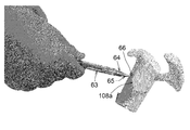
- Work 25 The fourth wire 66 (FIG. 19 (A)) is inserted into the body from the second portal 111 (FIG. 7) toward the scapula neck 108a, and the tip of the fourth wire 66 is inserted into the scapula neck 108a. (See FIG. 20).
- Work 26 As shown in FIG. 21, the fourth sleeve 65 is moved into the body by moving the fourth sleeve 65 along the fourth wire 66 while passing the fourth wire 66 through the cavity of the fourth sleeve 65. It is inserted into the scapula neck 108a, and then the fourth wire 66 is pulled out from the cavity of the fourth sleeve 65.
- Work 27 By passing the fifth wire 67-1 (FIG.
- the second sleeve 63 is moved along the third sleeve 64 while the third sleeve 64 is passed through the cavity of the second sleeve 63 (FIG. 18).
- the second sleeve 63 is inserted into the body and guided to the scapular neck 108a.
- Work 29 The third sleeve 64 and the fourth sleeve 65 are pulled out of the body from the second portal 111 (FIG. 7) so that only the fifth wire 67-1 has passed through the cavity of the second sleeve 63 (FIG. 7). 22 indicates a state after the work 29 has been performed).
- Work 30 With the base end side of the polishing tool main body 60b (FIGS.
- Work 31 By rotating the polishing tool 60 by driving the electric tool 70, the surface of the scapula neck 108a is polished by the tip surface of the polishing tool tip 60a, and the surface of the scapula neck 108a is flattened. After that, the polishing tool 60 and the second sleeve 63 are pulled out of the body from the second portal 111 (FIG. 7).
- Work 32 The surgical instrument 1 is inserted into the body by moving the surgical instrument 1 along the fifth wire 67-1 while passing the fifth wire 67-1 through the notch 10 of the surgical instrument 1.
- Task 33 Insert the fourth wire 66 (FIG. 19 (A)) from the second portal 111 (FIG. 7) into the body toward the scapula neck 108a, and insert the tip 66a of the fourth wire 66 into the surgical instrument. It is passed through the through hole 12 of 1 and brought into contact with the surface of the scapula neck 108a.
- Work 34 The fourth sleeve 65 is inserted into the body by moving the fourth sleeve 65 along the fourth wire 66 while passing the fourth wire 66 through the cavity of the fourth sleeve 65 (FIG. 18). The fourth wire 66 is pulled out from the cavity of the fourth sleeve 65.
- Work 35 By passing the fifth wire 67-2 (FIG. 24, 19 (b)) through the cavity of the fourth sleeve 65, the fifth wire 67-2 is inserted into the body and guided to the scapula neck 108a.
- FIG. 24 shows a state in which the fifth wire 67-2 is passed through the through hole 12 and pierced into the scapula neck 108a.
- the fourth sleeve 65 is not shown. Yes).
- Work 36 After pulling out the fourth sleeve 65 and the fifth wire 67-2 from the second portal 111 (FIG. 7), the surgical instrument 1 is removed from the fifth wire 67-1 by moving the surgical instrument 1.
- the fourth sleeve 65 is moved along the fourth wire 66 to move the fourth sleeve 65.
- Work 39 The third sleeve 64 is inserted into the body by moving the third sleeve 64 along the fourth sleeve 65 while passing the fourth sleeve 65 through the cavity of the third sleeve 64 (FIG. 18).
- Guided to the scapula neck 108a see FIG. 27
- the second sleeve 63 is passed along the third sleeve 64 with the third sleeve 64 passed through the cavity of the second sleeve 63 (FIG. 18).
- the polishing tool 60 By passing the fourth wire 66 through the cavity of 60, the polishing tool 60 is inserted into the body and guided to the scapula neck 108a, and the tip of the polishing tool 60a is projected from the tip of the second sleeve 63. The tip surface of the tip portion 60a of the polishing tool is brought into contact with the surface of the scapula neck portion 108a (see FIG. 30).
- Work 42 By rotating the polishing tool 60 by driving the electric tool 70, the surface of the scapula neck 108a is polished by the tip surface of the polishing tool tip 60a, and the surface of the scapula neck 108a is flattened. Is done.
- the third sleeve 64 can be inserted into the body using the four sleeves 65 as a guide and the fourth sleeve 65 can be inserted into the body using the fourth wire 66 as a guide, the work of securing a space for passing the polishing tool 60 into the body can be smoothly advanced. be able to.
- the tip portion 65a of the fourth sleeve 65 and the tip portion 64a of the third sleeve 64 each exhibit a tapered shape (the fourth sleeve tip portion 65a and the third sleeve tip portion 64a are attached to these tips.
- the outer diameter gradually decreases as it approaches), so that the fourth sleeve 65 and the third sleeve 64 can be smoothly inserted into the body. From this point as well, the work of securing a space for passing the polishing tool 60 can be smoothly proceeded.
- the tip portion 66a of the fourth wire 66 (FIG. 19 (A)) has a rounded shape, the fourth wire 66 can be attached to the scapula in the work 25, 33, 37 without damaging the inside of the body. It can be moved towards the neck 108a.
- the guide wire 27 inserted into the body from the second portal 111 is inserted into the cavity of the spiral 21 and the shoulder formed by the operation 27.
- the guide wire 27 is pierced into the scapula neck 108a, and the guide wire 28 inserted into the body from the second portal 111 is formed by the cavity of the spiral 23 and the work 35. It is considered that the guide wire 28 is pierced into the scapula neck 108a by passing through the hole of the scapula neck 108a.
- the guide wire 30 inserted into the body from the second portal 111 is inserted into the hole of the coracoid process 103 into which the spiral 23 (FIGS. 5 to 8) is screwed, and the work 35. It is passed through the hole in the formed scapular neck 108a.
- Example of modification of work 31 By rotating the polishing tool 60 by driving the electric tool 70, the surface of the scapula neck 108a is polished by the tip surface of the polishing tool tip 60a, and the surface of the scapula neck 108a is formed. Flattening is performed, after which the polishing tool 60, the second sleeve 63, and the fifth wire 67-1 are pulled out of the body from the second portal 111 (FIG. 7).
- the guide wire 27 inserted into the body from the second portal 111 is inserted into the cavity of the spiral 21 and the hole of the scapula neck 108a formed by the work 27.
- the surface of the coracoid process 103 is surely in contact with the surface of the scapula neck 108a flattened in the flattening step.
- the coracoid process 103 can be fixed to the scapula neck 108a by the spiral 26 (FIGS. 8 to 10).
- the guide wire 22 (FIG. 5 (A)), the guide wire 24 (FIG. 5 (B)), the guide wire 27 (FIG. 8)), the guide wire 28 (FIG. 8), and the guide wire 30 (FIG. 8). It is not an essential condition to use 10 (A) and 10 (B).
- the spiral 21 is inserted into the body from the first portal 104, the spiral 21 is passed through the notch 10, and screwed into the coracoid process 103, or in the third step (FIG. 5).
- the spiral 23 is inserted into the body from the first portal 104, the spiral 23 is passed through the through hole 12 and screwed into the coracoid process 103, and in the sixth step (FIG. 8), the spiral 23 is screwed into the coracoid process 103.
- the unfilled spiral 21 is taken out of the body from the second portal 111, or the spiral 26 is inserted into the body from the second portal 111 in the sixth step (FIG. 8), and the spiral 26 is passed through the notch 10.
- the spiral 29 is inserted into the body from the second portal, and the spiral 29 is passed through the hole of the coracoid process 103 into which the spiral 23 is screwed to pass the coracoid process 103.
- screwing into the shoulder blade neck 108a may be performed by using a known means other than the guide wire.
- the spirals 21, 23, 26, 29 may not have a hollow structure (spirals 21, 23, 29). 26 and 29 may not have a cavity).
Landscapes
- Health & Medical Sciences (AREA)
- Life Sciences & Earth Sciences (AREA)
- Surgery (AREA)
- Orthopedic Medicine & Surgery (AREA)
- Medical Informatics (AREA)
- Engineering & Computer Science (AREA)
- Biomedical Technology (AREA)
- Heart & Thoracic Surgery (AREA)
- Nuclear Medicine, Radiotherapy & Molecular Imaging (AREA)
- Molecular Biology (AREA)
- Animal Behavior & Ethology (AREA)
- General Health & Medical Sciences (AREA)
- Public Health (AREA)
- Veterinary Medicine (AREA)
- Dentistry (AREA)
- Oral & Maxillofacial Surgery (AREA)
- Surgical Instruments (AREA)
Abstract
烏口突起を肩甲骨頸部に近接させることを容易に実現可能な手術器械を提供する。 本発明の手術器械1は、第一方向に延びる柄2と、柄2の先端から第二方向に延びる傾斜部3とを備える。傾斜部3が延びる第二方向は、柄2が延びる第一方向に対して95°以上115°以下の角度αで傾斜しており、傾斜部3の外縁には、螺旋が通される切り欠け10が形成されている。
Description
本発明は、烏口突起を肩甲骨頸部に移植するために使用される手術器械、当該手術器械を備える医療器具セット、及び烏口突起を肩甲骨頸部に移植する方法に関する。
従来、反復性肩関節脱臼に対する手術として、肩甲骨の烏口突起を肩甲骨頸部に移植する手術(以下、烏口突起移行術)が行なわれている。当該烏口突起移行術が直視下で行われる場合には、筋肉への侵襲と術後の関節拘縮が生じる虞があり、これらの症状がスポーツ選手に生じた場合、競技への復帰が困難となっていた。上記の問題を克服するためには、関節鏡視下の烏口突起移行術が有用であり、この関節鏡視下の烏口突起移行術として、非特許文献1に開示される移行術が知られている。この移行術では、以下の工程A~工程Gが実施される。
工程A:図32に示すように、肩甲下筋100を貫かせたスイッチングスティック101を上下方向に動かすことで、肩甲下筋100に切開口102を形成することが行なわれる(図32(A)は、スイッチングスティック101が肩甲下筋100を貫く以前の状態を示し、図32(B)は、肩甲下筋100を貫かせたスイッチングスティック101を上向きに傾動させた状態を示し、図32(C)は、肩甲下筋100を貫かせたスイッチングスティック101を下向きに傾動させた状態を示す)。
工程B:図33(A)及び図33(B)に示すように、烏口突起103の直上の位置で皮膚に形成された第一ポータル104からガイドワイヤー105を体内に挿入して、ガイドワイヤー105を烏口突起103に突き刺し、この後、中空螺旋106の空洞にガイドワイヤー105を通した状態で、ガイドワイヤー105に沿って中空螺旋106を烏口突起103に向けて移動させて、烏口突起103に中空螺旋106を捩じ込み、この後、ガイドワイヤー105を第一ポータル104から体外に引き出すことが行なわれる(図33(A)は1本目の中空螺旋106を烏口突起103に捩じ込む作業を示し、図33(B)は2本目の中空螺旋106を烏口突起103に捩じ込む作業を示す)。
工程C:図34に示すように、第一ポータル104から挿入した骨ノミ107によって、肩甲骨108から烏口突起103を切断する(この際には、烏口突起103に共同腱109が付いたままの状態で、烏口突起103が切断される)。
工程D:図35(A)及び図35(B)に示すように、第一ポータル104から体内に挿入した鉗子110で烏口突起103を把持して、鉗子110を下側に移動させることで、切開口102の手前に烏口突起103を移動させる。
工程E:図36(A)及び図36(B)に示すように、鉗子110から烏口突起103を外して、烏口突起103を体液中に浮遊させた状態で、切開口102の前方における皮膚の位置に形成された第二ポータル111からプラスチック製の筒体112を体内に挿入して、筒体112の先端の開口113に螺旋106の頭部を入れる。
工程F:図37(A)に示すように、筒体112を前進させることで、烏口突起103を、切開口102に入れて、肩甲骨頸部108aに近傍させる。
工程G:図37(A)に示すように、筒体112の空洞112aを通過させた長尺の螺旋113を、螺旋106の空洞に通して、烏口突起103に捩じ込んだ後、第二ポータル111から筒体112を体外に引き出す(図37(B)は、筒体112を体外に引き出した後の状態を示す)。
Laffosse L, Lejeune E, Bourchard A, et al., The arthroscopic Latarjet procedure for the treatment of anterior shoulder instability. Arthroscopy: The Journal of Arthroscopy and Related Surgery, Vol 23, No11 (November), 2007: pp1242.e1-1242.e5.
ところで上記従来の烏口突起移行術は、工程E(図36)で、体液中に浮遊する烏口突起103を、筒体112で捉える作業が非常に困難であった(体液中に烏口突起103が浮遊する状態で、筒体112の開口113に螺旋106の頭部を入れる作業が非常に困難であった)。このため従来の烏口突起移行術は、烏口突起103を肩甲骨頸部108aに近接させるために長い時間を要していた。また上記工程Eが非常に困難であることで、関節鏡視下での作業が断念されて、直視鏡下での作業に変更される事態も生じていた。
さらに上記従来の烏口突起移行術では、工程G(図37)で筒体112を前進させた結果、肩関節の近傍にある神経血管系200が、肩甲下筋100と共同腱109とによって前後方向に挟み込まれる(上記の神経血管系200には、筋皮神経200a、腋窩神経200b、鎖骨下動脈200cなどが含まれる)。そしてこの挟み込みがきつい場合には、神経血管系200が損傷することによる合併症が生じ得る。例えば上記挟み込みがきついことで筋皮神経200aが損傷した場合には、肘が曲がらなくなる合併症が生じ得る。また上記挟み込みがきついことで腋窩神経200bが麻痺した場合には、肩が上がらなくなる合併症が生じ得る。
本発明は、上記事項に鑑みてなされたものであって、本発明の目的は、烏口突起を肩甲骨頸部に近接させることを容易に実現可能な手術器械、及び当該手術器械を備えた医療機器セットを提供することである。また本発明の他の目的は、神経血管系を損傷させることなく、烏口突起を肩甲骨頸部に近接させることが可能な烏口突起の移植方法を提供することである。
上記目的を達成するため、本発明は、次の項に記載の主題を包含する。
項1.烏口突起を肩甲骨頸部に移植するために使用される手術器械であって、
第一方向に延びる柄と、
前記柄の先端から第二方向に延びる傾斜部とを備え、
前記傾斜部が延びる第二方向は、前記柄が延びる前記第一方向に対して95°以上115°以下の角度で傾斜しており、
前記傾斜部の外縁には、螺旋を通す切り欠けが形成される手術器械。
第一方向に延びる柄と、
前記柄の先端から第二方向に延びる傾斜部とを備え、
前記傾斜部が延びる第二方向は、前記柄が延びる前記第一方向に対して95°以上115°以下の角度で傾斜しており、
前記傾斜部の外縁には、螺旋を通す切り欠けが形成される手術器械。
項2.前記傾斜部には、螺旋を通す貫通孔が形成される項1に記載の手術器械。
項3.前記傾斜部における前記貫通孔の側方の位置には、外方に突出する突出部が形成されている項2に記載の手術器械。
項4.前記柄は、柄本体の基端側に、持ち手とされる把持部が接続されたものであり、
前記傾斜部は、前記柄本体の先端から前記第二方向に延びており、
前記把持部と前記傾斜部との間における前記柄本体の範囲の長さは、8cm以上12cm以下とされる項1乃至3のいずれかに記載の手術器械。
前記傾斜部は、前記柄本体の先端から前記第二方向に延びており、
前記把持部と前記傾斜部との間における前記柄本体の範囲の長さは、8cm以上12cm以下とされる項1乃至3のいずれかに記載の手術器械。
項5.項4に記載の手術器械と、
前記烏口突起を切断するために使用される切断具とを含み、
前記切断具は、持ち手として使用される厚肉部と、当該厚肉部よりも厚さの薄い薄肉部とが連なったものであり、前記厚肉部から最も遠い前記薄肉部の先端が、最も薄い刃先とされており、
前記薄肉部の長さは、6cm以上8cm以下とされる医療器具セット。
前記烏口突起を切断するために使用される切断具とを含み、
前記切断具は、持ち手として使用される厚肉部と、当該厚肉部よりも厚さの薄い薄肉部とが連なったものであり、前記厚肉部から最も遠い前記薄肉部の先端が、最も薄い刃先とされており、
前記薄肉部の長さは、6cm以上8cm以下とされる医療器具セット。
項6.項1乃至4のいずれかに記載の手術器械と、
第一ワイヤーと、
第二ワイヤーと、
第三ワイヤーと、
第一スリーブとを含む医療器具セットであって、
前記第一ワイヤー、前記第二ワイヤー、前記第三ワイヤー、及び前記第一スリーブを、それぞれ前記手術器械の前記切り欠けに通すことが可能であり、
前記第一ワイヤーは、中空の筒体であり、前記第一ワイヤーの空洞に前記第三ワイヤーを挿通することが可能であり、前記第一ワイヤーの先端部の外周面には螺旋状に延びる溝が形成され、
前記第二ワイヤーの先端部は、丸みを帯びた形状とされ、
前記第三ワイヤーの先端部は、角のある先細り状とされ、
前記第一スリーブは、中空の筒体であり、当該記第一スリーブの空洞に、前記第一ワイヤー、前記第二ワイヤー、及び前記第三ワイヤーを、それぞれ挿通することが可能である医療器具セット。
項7.項1乃至4のいずれかに記載の手術器械と、
研磨具と、
第二スリーブと、
第三スリーブと、
第四スリーブと、
第四ワイヤーと、
第五ワイヤーとを含む医療器具セットであって、
前記第二スリーブ、前記第三スリーブ、前記第四スリーブ、及び前記研磨具は、それぞれ中空の筒体であり、
前記第二スリーブの空洞に前記第三スリーブを挿通すること、前記第三スリーブの空洞に前記第四スリーブを挿通すること、前記第四スリーブの空洞に前記第四ワイヤー又は前記第五ワイヤーを挿通すること、及び前記第二スリーブの空洞に前記研磨具を挿通することが可能であり、
前記第四ワイヤーは、前記研磨具の空洞及び前記第四スリーブの空洞に挿通することが可能であり、前記第四ワイヤーの先端部は、丸みを帯びた形状とされ、
前記第五ワイヤーは、前記研磨具の空洞、前記第四スリーブの空洞、及び前記手術器械の前記切り欠けに挿通することが可能であり、前記第五ワイヤーの先端部は、角のある先細り状とされ、
前記研磨具の基端部が電動具に接続された状態で、当該電動具を作動させることで前記研磨具を中心軸回りに回転させることが可能であり、前記研磨具の先端面を前記肩甲骨頸部の表面に接触させた状態で、前記研磨具を回転させることで、前記研磨具の先端面によって前記肩甲骨頸部の表面を研磨することが可能である医療機器セット。
項8.前記第三スリーブの先端部と、前記第四スリーブの先端部とは、それぞれ先細りの形状を呈する項7に記載の医療器具セット。
項9.項1乃至4のいずれかに記載の手術器械を用いて前記烏口突起を前記肩甲骨頸部に移植する方法であって、
前記肩甲骨頸部の近傍において、肩甲下筋に切開口を形成する第一工程と、
前記肩甲骨頸部の直上の位置で皮膚に形成された第一ポータルから前記手術器械を体内に挿入して、前記傾斜部を前記烏口突起に当接させる第二工程と、
前記第一ポータルから体内に挿入した一の螺旋を、前記傾斜部の切り欠けに通して、前記烏口突起に捩じ込むことで、前記一の螺旋によって前記傾斜部を前記烏口突起に締結する第第三工程と、
前記第一ポータルから挿入した骨ノミによって、前記烏口突起に共同腱が付いたままの状態で、前記烏口突起を肩甲骨から切断する第四工程と、
前記手術器械を下側に移動させることで、前記烏口突起を下側に移動させて、当該烏口突起を、前記切開口に入れて、前記肩甲骨頸部に近接させる第五工程と、
前記烏口突起への前記一の螺旋の捩じ込みを解除して、前記切開口の前方の位置で皮膚に形成された第二ポータルから前記一の螺旋を体外に取り出すとともに、前記一の螺旋よりも長尺の二の螺旋を、前記第二ポータルから体内に挿入して、前記切り欠けに通して、前記烏口突起及び前記肩甲骨頸部に捩じ込む第六工程と、
前記手術器械を動かすことで、前記二の螺旋から前記手術器械を外して、前記第一ポータルから前記手術器械を体外に取り出す第七工程とを有する方法。
項10.前記第三工程では、前記第一ポータルから体内に挿入した一のガイドワイヤーを、前記傾斜部の切り欠けに通して、前記烏口突起に突き刺し、この後、前記一の螺旋の空洞に前記一のガイドワイヤーを通した状態で、前記一の螺旋を前記一のガイドワイヤーに沿って前記切り欠けに向けて移動させて、前記一の螺旋を前記切り欠けに通して前記烏口突起に捩じ込み、この後、前記一のガイドワイヤーを前記第一ポータルから体外に引き出すことが行なわれ、
前記第六工程では、前記第二ポータルから二のガイドワイヤーを体内に挿入して、当該二のガイドワイヤーを、前記一の螺旋の空洞に通して、前記肩甲骨頸部に突き刺し、この後、前記烏口突起への前記一の螺旋を捩じ込みを解除するとともに、当該一の螺旋を、前記二のガイドワイヤーに沿って移動させて、前記第二ポータルから体外に取り出し、この後、前記一の螺旋よりも長尺の二の螺旋の空洞に前記二のガイドワイヤーを通した状態で、前記二のガイドワイヤーに沿って前記二の螺旋を前記切り欠けに向けて移動させて、当該二の螺旋を、前記切り欠けに通して、前記烏口突起及び前記肩甲骨頸部に捩じ込み、この後、前記二のガイドワイヤーを前記第二ポータルから体外に引き出すことが行なわれる項9に記載の方法。
前記第六工程では、前記第二ポータルから二のガイドワイヤーを体内に挿入して、当該二のガイドワイヤーを、前記一の螺旋の空洞に通して、前記肩甲骨頸部に突き刺し、この後、前記烏口突起への前記一の螺旋を捩じ込みを解除するとともに、当該一の螺旋を、前記二のガイドワイヤーに沿って移動させて、前記第二ポータルから体外に取り出し、この後、前記一の螺旋よりも長尺の二の螺旋の空洞に前記二のガイドワイヤーを通した状態で、前記二のガイドワイヤーに沿って前記二の螺旋を前記切り欠けに向けて移動させて、当該二の螺旋を、前記切り欠けに通して、前記烏口突起及び前記肩甲骨頸部に捩じ込み、この後、前記二のガイドワイヤーを前記第二ポータルから体外に引き出すことが行なわれる項9に記載の方法。
項11.前記手術器械は、項2又は3に記載された手術器械であり、
前記第七工程の後に実施される第八工程をさらに有し、
前記第三工程では、前記第一ポータルから体内に挿入した三の螺旋を、前記貫通孔に通して、前記烏口突起に捩じ込むことで、前記三の螺旋によって前記傾斜部を前記烏口突起に締結することが行なわれ、
前記第六工程では、前記烏口突起への前記三の螺旋の捩じ込みを解除して、前記第二ポータルから前記三の螺旋を体外に取り出すことが行なわれ、
前記第八工程では、前記三の螺旋よりも長尺の四の螺旋を、前記第二ポータルから体内に挿入するとともに、当該四の螺旋を、前記三の螺旋が捩じ込まれていた前記烏口突起の孔に通して、前記烏口突起及び前記肩甲骨頸部に捩じ込むことが行なわれる項9又は10に記載の方法。
項12.前記第三工程では、前記第一ポータルから体内に挿入した三のガイドワイヤーを、前記貫通孔に通して、前記烏口突起に突き刺し、この後、前記三の螺旋の空洞に前記三のガイドワイヤーを通した状態で、前記三の螺旋を前記三のガイドワイヤーに沿って前記貫通孔に向けて移動させて、当該三の螺旋を、前記貫通孔に通して前記烏口突起に捩じ込み、この後、前記三のガイドワイヤーを前記第一ポータルから体外に引き出すことが行なわれ、
前記第六工程では、前記第二ポータルから四のガイドワイヤーを体内に挿入して、前記四のガイドワイヤーを、前記三の螺旋の空洞に通して、前記肩甲骨頸部に突き刺し、この後、前記烏口突起への前記三の螺旋を捩じ込みを解除するとともに、前記三の螺旋を、前記四のガイドワイヤーに沿って移動させて、前記第二ポータルから体外に出すとともに、前記四のガイドワイヤーを前記第二ポータルから体外に引き出すことが行なわれ、
前記第八工程では、前記第二ポータルから五のガイドワイヤーを体内に挿入して、当該五のガイドワイヤーを、前記三の螺旋が捩じ込まれていた前記烏口突起の孔と、前記四のガイドワイヤーが突き刺されていた前記肩甲骨頸部の孔とに通し、この後、前記三の螺旋よりも長尺の四の螺旋の空洞に前記五のガイドワイヤーを通した状態で、前記五のガイドワイヤーに沿って前記四の螺旋を移動させて、当該四の螺旋を、前記烏口突起の孔と前記肩甲骨頸部の孔とに通すことで、前記烏口突起及び前記肩甲骨頸部に捩じ込み、この後、前記五のガイドワイヤーを前記第二ポータルから体外に引き出すことが行なわれる項11に記載の方法。
本発明の手術器械及び医療セットによれば、傾斜部が柄本体に対して95°以上115°以下の角度で傾斜していることで、ポータルを形成することに適した烏口突起の直上の位置を柄が通過する条件下で、肩甲骨に付いている烏口突起に傾斜部を当接させることができる。そしてこのように傾斜部を烏口突起に当接させれば、烏口突起が肩甲骨に付いて安定している状態で、螺旋を切り欠けに通して烏口突起に捩じ込む作業を行なうことができる。このため、螺旋を用いて傾斜部を烏口突起に接続することを容易に行える。そしてこのように傾斜部が烏口突起に接続された状態で、烏口突起を肩甲骨から切断すれば、手術器械を下側に動かす簡易な作業によって、烏口突起を肩甲骨頸部に近接させることができる。以上の理由から、本発明の手術器械及び医療セットによれば、容易に烏口突起を肩甲骨頸部に近接させることができる。
本発明の移植方法によれば、第五工程で手術器械を下側に移動させて烏口突起を肩甲骨頸部に近接させることに伴い、共同腱及び烏口突起が下側に移動するので、共同腱或いは烏口突起の押圧によって、肩関節の近傍にある神経血管系を下側に移動させることができる。これにより、肩甲下筋と共同腱とによる前後方向(水平方向)の神経血管系の挟み込みを弱くすることができるので、神経血管系を損傷させることなく、烏口突起を肩甲骨頸部に近接させることができる。これにより神経血管系の損傷による合併症が生じることを回避できる。
以下、本発明の実施形態について図面を参照しながら説明する。
図1は、本発明の実施形態に係る手術器械1を示す斜視図(写真)である。図2(A)は、後述する柄2に対して垂直な方向から手術器械1を視た状態を示す平面図である。図2(B)は、後述する傾斜部3に対して垂直な方向から手術器械1を視た状態を示す平面図である。図2(C)は、手術器械1の側面図である。図3~図10は、手術器械1を用いて関節鏡視下で行なわれる烏口突起103の移植方法の手順を示す概略図である。
本実施形態に係る手術器械1(図1,図2)は、烏口突起103を肩甲骨頸部108aに移植するために使用される(具体的には、手術器械1は、烏口突起103を肩甲骨頸部108aに近接させて、螺旋で烏口突起103を肩甲骨頸部108aに固定するために使用される)。
図1及び図2に示すように、手術器械1は、第一方向に延びる柄2と、柄2の先端から第二方向に延びる傾斜部3とを備える。傾斜部3が延びる第二方向は、柄2が延びる第一方向に対して、95°以上115°以下の角度αで傾斜する(角度αについては図2(C)参照)。
柄2は、柄本体4の基端側に、持ち手とされる把持部5が接続されたものである。
把持部5は、先端(一端)に開口6(図2(B))を有する筒体であり、ステンレス合金、チタン合金、或いはアルミニウム合金から形成される。把持部5の長さL1(図1)は、例えば5cm以上とされる。把持部5の幅H1(図2(A))は、例えば1cm以上2cm以下とされる。手術器械1の使用時には、ユーザは、把持部5を把持して、手術器械1を操作する。
柄本体4は、ステンレス合金、チタン合金、或いはアルミニウム合金から形成された棒材である。柄本体4の横断面は、矩形を呈しており、把持部5の横断面の寸法(幅、高さ)は、柄本体4の横断面の寸法(幅、高さ)よりも大きくされる。柄本体4の基端側への把持部5の接続は、把持部5の開口6から柄本体4の基端側が把持部5の内部に挿入された状態で、柄本体4の基端側が把持部5に固定されることで行なわれる。傾斜部3は柄本体4の先端から延びており、把持部5と傾斜部3との間における柄本体4の範囲の長さL2(図1)は、8cm以上12cm以下とされる。柄本体4の幅H2(図2(A))は、例えば0.4cm以上0.8cm以下とされる。
なお柄本体4の横断面の形状は、矩形以外の形状とされてもよい(例えば、柄本体4の横断面は、円形或いは楕円形とされてもよい)。また上記以外の公知の方法によって、把持部5が柄本体4の基端側に接続されてもよい。また把持部5は、柄本体4の基端側に接続されるように、柄本体4と一体に成形されたものとされてもよい。この場合も、把持部5の横断面の寸法(幅、高さ)は、柄本体4の横断面の寸法(幅、高さ)よりも大きいものとされる。
傾斜部3は、柄本体4の先端から第二方向に延びる板状体である。傾斜部3は、ステンレス合金、チタン合金、或いはアルミニウム合金から形成されるものであり、柄本体4と一体に成形される。傾斜部3の長さL3(図1)は、例えば1.5cm以上2.5cm以下とされ、傾斜部3の幅H3(図2(B))は、例えば1.2cm以上1.5cm以下とされる(傾斜部3の幅H3は傾斜部3の最大幅を意味する)。
傾斜部3の先端側の外縁には、螺旋を通す切り欠け10が形成される。切り欠け10は外方に開口するものであり、烏口突起103に捩じ込まれる螺旋21(図5~図8)や、烏口突起103及び肩甲骨頸部108aに捩じ込まれる螺旋26(図8~図10)が、切り欠け10に通される。図1及び図2に示す例では、傾斜部3の先端側に二股部11,11が形成されており、二股部11,11の間の空間によって、切り欠け10が構成されており、切り欠け10の横断面は半円形を呈している。
傾斜部3の基端側(柄2側)には、螺旋を通す貫通孔12が形成される。貫通孔12の横断面は円形を呈しており、烏口突起103に捩じ込まれる螺旋23(図5~図8)が貫通孔12に通される。傾斜部3における貫通孔12の側方の位置には、外方に突出する突出部13が形成される(上記の「貫通孔12の側方の位置」とは、貫通孔12に対して傾斜部3の幅方向の外側の位置を意味し、上記の「傾斜部3の幅方向」は、傾斜部3の長手方向に対して直交する方向を意味する)。突出部13は、手術器械1の使用時に貫通孔12の位置を把握するための目印として設けられる。
なお切り欠け10の形状は、螺旋21,26を出し入れ可能な開口を有した任意の形状とされ得る。また貫通孔12の形状も、螺旋23を通すことの可能な任意の形状とされ得る。具体的には、上記の螺旋21,23,26は、大径の頭部から小径の螺旋部が延びたものであり、切り欠け10の形状は、開口から螺旋21,26の螺旋部を出し入れすることが可能であり、且つ、螺旋21,26の螺旋部を切り欠け10に通した状態で、切り欠け10の周囲にある傾斜部3の表面に、螺旋21,26の頭部を当接させることの可能な形状とされ得る。また貫通孔12の形状は、螺旋23の螺旋部を貫通孔12に通した状態で、貫通孔12の周囲にある傾斜部3の表面に、螺旋23の頭部を当接させることの可能な形状とされ得る。
また切り欠け10の位置や、貫通孔12の位置は、図1,図2に示す位置に限定されない。例えば、傾斜部3の基端側(柄2側)の外縁に切り欠け10が形成されてもよい。また傾斜部3の先端側に貫通孔12が形成されてもよい。また複数の切り欠け10が傾斜部3に形成されてもよく、複数の貫通孔12が傾斜部3に形成されてもよい。
また貫通孔12及び突出部13は、必ずしも必要ではなく、傾斜部3に形成されなくてもよい。
以下、上記の手術器械1を用いて関節鏡視下で行なわれる「烏口突起103を肩甲骨頸部108aに移植する方法(烏口突起103を肩甲骨頸部108aに近接させて、螺旋で烏口突起103を肩甲骨頸部108aに固定する方法)」を、図3~図10を参照しながら説明する。
まず肩甲骨頸部108aの近傍において、肩甲下筋100に切開口102を形成する第一工程が実施される(図3)。この第一工程では、例えば図3に示すように、肩甲下筋100を貫かせたスイッチングスティック20を上下方向に動かすことで、肩甲下筋100に切開口102を形成することが行なわれる(図3(A)は、スイッチングスティック20が肩甲下筋100を貫く以前の状態を示し、図3(B)は、スイッチングスティック20を上向きに傾動させた状態を示し、図3(C)は、スイッチングスティック20を下向きに傾動させた状態を示す)。なお第一工程では、上記以外の公知の方法で、切開口102が形成されてもよい。
ついで図4に示すように、烏口突起103の直上の位置で皮膚に形成された第一ポータル104から手術器械1を体内に挿入して、傾斜部3を烏口突起103に当接させる第二工程が実施される。具体的には、ユーザが把持部5(図1,図2)を把持して手術器械1を操作することで、柄本体4及び傾斜部3を第一ポータル104から体内に挿入して、傾斜部3を烏口突起103に当接させることが行なわれる。第一ポータル104と烏口突起103との間の距離を短くして、患者への負担を軽減する観点から、第一ポータル104は、烏口突起103の直上の位置に形成される。
また図1及び図2に示した例のように、傾斜部3に貫通孔12及び突出部13が形成されている場合には、第二工程(図4)では、貫通孔12を位置決めするための目印として突出部13を使用して、鳥口突起103の所望の位置に貫通孔12を配置することが行なわれる。
ついで第一ポータル104から中空構造の螺旋21を体内に挿入して、当該螺旋21を、傾斜部3の切り欠け10に通して、烏口突起103に捩じ込むことで、螺旋21によって傾斜部3を烏口突起103に締結する第三工程が実施される(図5)。この際には、図5(A)に示すように、第一ポータル104から体内に挿入したガイドワイヤー22を、切り欠け10に通して、烏口突起103に突き刺すことが行なわれる。そしてこの後、螺旋21の空洞にガイドワイヤー22を通した状態で、螺旋21をガイドワイヤー22に沿って切り欠け10に向けて移動させて、当該螺旋21を切り欠け10に通して烏口突起103に捩じ込み、この後、ガイドワイヤー22を第一ポータル104から体外に引き出すことが行なわれる(図5(B)は、ガイドワイヤー22が体外に引き出された後の状態を示す)。また第三工程では、螺旋21の螺旋部が、傾斜部3の切り欠け10に通されて、烏口突起103に捩じ込まれた状態で、螺旋21の頭部と烏口突起103との間に傾斜部3が挟み込まれることで、螺旋21によって傾斜部3が烏口突起103に締結される。
また図1及び図2に示した例のように、傾斜部3に貫通孔12が形成されている場合には、第三工程において、第一ポータル104から中空構造の螺旋23(図5(B))を体内に挿入して、当該螺旋23を、傾斜部3の貫通孔12に通して、烏口突起103に捩じ込むことで、螺旋23によって傾斜部3を烏口突起103に締結する作業も行なわれる。この作業では、図5(B)に示すように、第一ポータル104から体内に挿入したガイドワイヤー24を、貫通孔12に通して、烏口突起103に突き刺すことが行なわれる。そしてこの後、螺旋23の空洞にガイドワイヤー24を通した状態で、螺旋23をガイドワイヤー24に沿って貫通孔12に向けて移動させて、螺旋23を、貫通孔12に通して烏口突起103に捩じ込み、この後、ガイドワイヤー24を第一ポータル104から体外に引き出すことが行なわれる(図5(B)は、螺旋23を貫通孔12に通す直前の状態を示す)。また上記の作業では、螺旋23の螺旋部を、傾斜部3の貫通孔12に通して、烏口突起103に捩じ込むことが行なわれることで、螺旋23の頭部と烏口突起103との間に傾斜部3が挟み込まれることで、螺旋23によって傾斜部3が烏口突起103に締結される。
上記の第三工程の後では、図6に示すように、第一ポータル104から挿入した骨ノミ25によって、烏口突起103に共同腱109が付いたままの状態で、烏口突起103を肩甲骨108から切断する第四工程が実施される。この際には、骨ノミ25を柄本体4に沿わせて、骨ノミ25を肩関節内に挿入することが行なわれる。その後、骨ノミ25を柄本体4に沿わせた状態で骨ノミ25の頭部(骨ノミ25の基端部)をハンマーで叩くことで、柄本体4に沿って骨ノミ25をスライドさせて、当該骨ノミ25によって烏口突起103を切断することが行なわれる。
ついで図7(A),図7(B),図7(C)に示すように、手術器械1を下側に移動させることで、共同腱109が付いている烏口突起103を下側に移動させて、当該烏口突起103を、肩甲下筋100の切開口102に入れて、肩甲骨頸部108aに近接させる第五工程が実施される。この際には、下側に移動する共同腱109或いは烏口突起103の押圧によって、肩関節の近傍にある神経血管系200も下側に移動する。神経血管系200には、筋皮神経200a、腋窩神経200b、及び鎖骨下動脈200cが含まれており、図7は、共同腱109の押圧によって、筋皮神経200a、腋窩神経200b、及び鎖骨下動脈200cが下側に移動する状態を示している。
ついで烏口突起103への螺旋21の捩じ込みを解除して、切開口102の前方の位置で皮膚に形成された第二ポータル111から螺旋21を体外に取り出すとともに、螺旋21よりも長尺であり中空構造を有する螺旋26を、第二ポータル111から体内に挿入して、切り欠け10に通し、烏口突起103及び肩甲骨頸部108aに捩じ込む第六工程が実施される(図8)。この際には、第二ポータル111から体内に挿入したガイドワイヤー27を、螺旋21の空洞に通して、肩甲骨頸部108aに突き刺すことが行なわれる。そしてこの後、烏口突起103への螺旋21を捩じ込みを解除するとともに、螺旋21を、ガイドワイヤー27に沿って移動させて、第二ポータル111から体外に取り出すことが行なわれる(図8(A)は、螺旋21が、ガイドワイヤー27に沿って、第二ポータル111に向かっているときの状態を示し、図8(B),図8(C)は、螺旋21が体外に取り出された後の状態を示す)。そしてこの後、螺旋26の空洞にガイドワイヤー27を通した状態で、ガイドワイヤー27に沿って螺旋26を切り欠け10に向けて移動させて、当該螺旋26を、切り欠け10に通して、烏口突起103及び肩甲骨頸部108aに捩じ込むことが行なわれ、この後、ガイドワイヤー27を第二ポータル111から体外に引き出すことが行なわれる(図8(B),図8(C)は、螺旋26が、切り欠け10に通されて、烏口突起103及び肩甲骨頸部108aに捩じ込まれた状態を示す)。
また図8(A)及び図8(B)に示すように、螺旋23が烏口突起103に捩じ込まれている場合には、第六工程で、烏口突起103への螺旋23を捩じ込みを解除して、第二ポータル111から螺旋23を体外に取り出すことも行なわれる。この作業では、図8(A)及び図8(B)に示すように、第二ポータル111から体内に挿入したガイドワイヤー28を、螺旋23の空洞に通して、肩甲骨頸部108aに突き刺すことが行なわれる。そしてこの後、図8(C)に示すように、烏口突起103への螺旋23を捩じ込みを解除するとともに、螺旋23を、ガイドワイヤー28に沿って移動させて、第二ポータル111から体外に出すとともに、ガイドワイヤー28を第二ポータル111から体外に引き出すことが行なわれる。
ついで図9に示すように、手術器械1を動かすことで、螺旋26から手術器械1を外して、第一ポータル104から手術器械1を体外に取り出す第七工程が実施される。この際には、螺旋26が通されている切り欠け10に開口があることで、手術器械1を螺旋26から容易に外すことができる(すなわち、螺旋26が切り欠け10(二股部11,11の間)から出るように、手術器械1を動かす簡易な作業を行なうことで、手術器械1を螺旋26から外すことができる)。
以上の作業によって、烏口突起103が肩甲骨頸部108aに移植された状態(螺旋26によって烏口突起103が肩甲骨頸部108aに固定された状態)になる。
なお第六工程(図8)で、烏口突起103に捩じ込まれていた螺旋23を体外に取り出すことが行なわれた場合には、第七工程(図9)の後に、図10に示すように、螺旋23よりも長尺であり中空構造を有する螺旋29を、第二ポータル111から体内に挿入して、当該螺旋29を、螺旋23(図5~図8)が捩じ込まれていた烏口突起103の孔に通して、烏口突起103及び肩甲骨頸部108aに捩じ込む第八工程が実施される。この際には、図10(A)に示すように、第二ポータル111からガイドワイヤー30を体内に挿入して、上記の螺旋23が捩じ込まれていた烏口突起103の孔と、ガイドワイヤー28(図8)が突き刺されていた肩甲骨頸部108aの孔とに、ガイドワイヤー30(図10)を通すことが行なわれる。そしてこの後、図10(B)に示すように、螺旋29の空洞にガイドワイヤー30を通した状態で、ガイドワイヤー30に沿って螺旋29を移動させて、螺旋29を、上記の烏口突起103の孔及び肩甲骨頸部108aの孔に通すことで、烏口突起103及び肩甲骨頸部108aに捩じ込むことが行なわれる。そしてこの後、ガイドワイヤー30を第二ポータル111から体外に引き出すことが行なわれる(図10(C)は、螺旋29が烏口突起103及び肩甲骨頸部108aに捩じ込まれて、ガイドワイヤー30が体外に引き出された後の状態を示す)。上記の第八工程(図10)が実施される場合には、螺旋26に加えて螺旋29によっても、烏口突起103が肩甲骨頸部108aに固定されることになる。
また第三工程(図5)で螺旋21,23を烏口突起103に捩じ込むことや、第六工程(図8)で烏口突起103への螺旋21,23の捩じ込みを解除して、螺旋21,23を体外に取り出すことや、第六工程(図8)で螺旋26を烏口突起103及び肩甲骨頸部108aに捩じ込むことや、第七工程(図9)で螺旋29を烏口突起103及び肩甲骨頸部108aに捩じ込むことは、公知のドライバーを使用することで実現され得る。当該ドライバーは、例えば、ガイドワイヤーを挿通可能な空洞を有するものであり、ドライバーの先端を螺旋21,23,26,29の空洞に挿入することで、ドライバーの先端に螺旋21,23,26,29を接続することが可能とされる。上記ドライバーの空洞は、ドライバーの先端で開口するものであり、螺旋21,23,26,29がドライバーの先端に接続された状態では、上記ドライバーの先端にある開口が、螺旋21,23,26,29の空洞内に位置することで、ドライバーの空洞と螺旋21,23,26,29の空洞とが連通した状態とされる。
螺旋21,23を烏口突起103に捩じ込む際や、螺旋26,29を烏口突起103及び肩甲骨頸部108aに捩じ込む際には、まず、ドライバーの先端を螺旋の空洞に挿入することで、ドライバーの先端に螺旋を接続することが行なわれる。そして螺旋の空洞及びドライバーの空洞にガイドワイヤーを通した状態で、ガイドワイヤーに沿って螺旋及びドライバーを体内に挿入して、螺旋の螺旋部が烏口突起103に突き当てられた状態とされる。そしてドライバーを回転させることで、螺旋の螺旋部を烏口突起103に捩じ込むこと、或いは螺旋の螺旋部を烏口突起103及び肩甲骨頚部108aに捩じ込むことが行なわれる。この後、ガイドワイヤーに沿ってドライバーを後退させることで、螺旋をドライバーの先端から外して、ドライバーを体外に取り出すことが行なわれる。
また烏口突起103への螺旋21,23の捩じ込みを解除して、螺旋21,23を体外に取り出す際には、ドライバーの空洞にガイドワイヤーを通した状態で、ガイドワイヤーに沿ってドライバーを体内に挿入して、ドライバーの先端を螺旋の空洞に挿入することで、ドライバーの先端に螺旋を接続することが行なわれる。そしてドライバーを回転させることで、烏口突起103への螺旋の捩じ込みを解除し、この後、ガイドワイヤーに沿ってドライバー及び螺旋を後退させることで、ドライバー及び螺旋を体外に取り出すことが行なわれる。
本実施形態に係る手術器械1によれば、傾斜部3が柄本体4に対して95°以上115°以下の角度α(図2(C))で傾斜していることで、図4に示すように、烏口突起103の直上の位置に形成した第一ポータル104を柄2が通過する条件下で、傾斜部3を烏口突起103に当接させることができる。そして図4に示すように傾斜部3を烏口突起103に当接させれば、図5に示すように、烏口突起103が肩甲骨108に付いていることで烏口突起103が安定している状態で(すなわち烏口突起103を肩甲骨108から切断する前の状態で)、螺旋21を、切り欠け10に通して、烏口突起103に捩じ込む作業を行なうことができる。このため、螺旋21を用いて傾斜部3を烏口突起103に接続することを容易に行える。そしてこのように傾斜部3が烏口突起103に接続された状態で、図6に示すように烏口突起103を肩甲骨108から切断すれば、図7に示すように手術器械1を下側に動かす簡易な作業によって、烏口突起103を肩甲骨頸部108aに近接させることができる。以上の理由から、本実施形態の手術器械1によれば、容易に烏口突起103を肩甲骨頸部108aに近接させることができる。
また本実施形態に係る移植方法によれば、図7に示す第五工程で、手術器械1を下側に移動させることで、共同腱109及び烏口突起103も下側に移動するので、当該共同腱109或いは烏口突起103の押圧によって、肩関節の近傍にある神経血管系200を下側に移動させることができる。これにより、肩甲下筋100と共同腱109とによる前後方向(水平方向)の神経血管系200の挟み込みを弱くすることができるので、神経血管系200が損傷することを防止できる。したがって神経血管系200の損傷による合併症が生じることを回避できる(例えば筋皮神経200aの損傷を防止できるので、肘が曲がらなくなる合併症が生じることを回避でき、また腋窩神経200bの損傷を防止できるので、肩が上がらなくなる合併症が生じることを回避できる)。
また本実施形態の手術器械1によれば、貫通孔12の側方の位置に突出部13が形成されるため、貫通孔12の位置決め用の目印として、突出部13を使用できる。これにより第二工程(図4)で、鳥口突起103の所望の位置に貫通孔12を配置することを容易に行える。
また上述した烏口突起103の移植方法を実施するために、図1,図2に示した手術器械1と、図11に示す切断具40とを含む医療器具セットが使用され得る。
切断具40は、図6に示す第四工程で、烏口突起103を切断する骨ノミ25として使用可能なものである。切断具40(図11)は、持ち手として使用される厚肉部41と、厚肉部41よりも厚さの薄い薄肉部42とが連なったものである。厚肉部41から最も遠い薄肉部42の先端42aが、最も薄い刃先とされており、薄肉部42の長さL4は、6cm以上8cm以下とされる。上記の切断具40が烏口突起103を切断する骨ノミ25(図6)として使用されれば、薄肉部42の長さL4(図11)が、柄本体4の長さL2(8cm以上12cm以下:図1)以下であることで、骨ノミ25(切断具40)を柄本体4に沿わせた状態で骨ノミ25(切断具40)の頭部をハンマーで叩くことを容易に行える。これにより、柄本体4の延長線上に沿って烏口突起103を切断することを容易に行なえる。したがって烏口突起103の切断位置を定めるガイドとして柄本体4を好適に使用できる。なお図11に示すように、薄肉部42は、把持部5から離間するにつれて、徐々に幅広となり、且つ徐々に薄くなるように形成されることが好ましい。また図11(B)に示すように、薄肉部42の先端側には、反りが形成されることが好ましい。
なお本発明は、切断具40を使用することを必須の条件とするものではなく、切断具40以外の器具が、烏口突起103を切断する骨ノミとして使用されてもよい。
また上述した烏口突起103の移植方法を実施するために、図1及び図2に示した手術器械1と、図12に示す第一ワイヤー50・第二ワイヤー51・第三ワイヤー52と、図13に示す第一スリーブ53とを含む医療器具セットが使用され得る。
第一ワイヤー50、第二ワイヤー51、第三ワイヤー52、及び第一スリーブ53は、それぞれ、手術器械1の切り欠け10及び貫通孔12に通すことが可能なものである。
図13に示す第一スリーブ53は、中空の筒体であり、ステンレス合金、チタン合金、或いはアルミニウム合金から形成される。第一スリーブ53の外径は例えば8mm以下とされ、第一スリーブ53の内径は例えば2mm以下とされる。
上記の第一スリーブ53は、ワイヤー50,51の移動をガイドするために使用されるものであり、ワイヤー50,51,52を、それぞれ第一スリーブ53の空洞に挿通することが可能とされる。
図12(A)に示す第一ワイヤー50は、中空の筒体であり、ステンレス合金、チタン合金、或いはアルミニウム合金から形成される。第一ワイヤー50の外径は例えば4mm以下とされ、第一ワイヤー50の内径は例えば2mm以下とされる。第一ワイヤー50の先端部の外周面には、螺旋状に延びる溝50aが形成される。
上記の第一ワイヤー50は、例えば、図5に示したガイドワイヤー22,24、及び図8に示したガイドワイヤー27,28として使用されるものであり、第一ワイヤー50(図12(A))の空洞に第三ワイヤー52(図12(C))を挿通することが可能とされる。
図12(B)に示す第二ワイヤー51は、ステンレス合金、チタン合金、或いはアルミニウム合金から形成されるものであり、第二ワイヤー51の外径は例えば2mm以下とされる。図14に示すように、第二ワイヤー51の先端部51aは、丸みを帯びた形状とされる。
上記の第二ワイヤー51は、第一スリーブ53の移動をガイドするために使用されるものである。また第二ワイヤー51は、図10に示すガイドワイヤー30としても使用され得る。
図12(C)に示す第三ワイヤー52は、、ステンレス合金、チタン合金、或いはアルミニウム合金から形成されるものであるものであり、第三ワイヤー52の外径は例えば2mm以下とされる。図15に示すように、第三ワイヤー52の先端部52aは、角のある先細り状とされる。
上記の第三ワイヤー52は、烏口突起103や肩甲骨頸部108aに孔を形成するために使用されるものであり、当該第三ワイヤー52によって烏口突起103や肩甲骨頸部108aに形成された孔に第一ワイヤー50(図12(A))を押し込むことで、上記第三ワイヤー52によって形成された孔を拡径させて、螺旋を捩じ込むことに適した孔を形成できる。
手術器械1、第一ワイヤー50,第二ワイヤー51,第三ワイヤー52、及び第一スリーブ53を含む医療器具セットが使用される場合、図5に示す第三工程では、螺旋21を、傾斜部3の切り欠け10に通して、烏口突起103に捩じ込んだ状態を実現するために、以下の作業1~5が順次行なわれる。
作業1:第一ポータル104(図5)から第二ワイヤー51(図12(B))を烏口突起103に向けて体内に挿入して、第二ワイヤー51の先端部を傾斜部3の切り欠け10に位置づける。
作業2:第一スリーブ53(図13)の空洞に第二ワイヤー51(図12(B))を通した状態で、第二ワイヤー51に沿って第一スリーブ53を移動させることで、第一スリーブ53を体内に挿入して烏口突起103へ導くとともに、第一スリーブ53の先端部を切り欠け10に位置づけて、この後、第一ポータル104(図5)から第二ワイヤー51を体外に引き出す(第一スリーブ53の空洞から第二ワイヤー51を引き抜く)。
作業3:第一スリーブ53の空洞に第三ワイヤー52(図12(C))を通すことで、第三ワイヤー52を体内に挿入して烏口突起103へ導くとともに、第一スリーブ53の先端から突出させた第三ワイヤー52を、切り欠け10に通して、烏口突起103に突き刺すことで、烏口突起103に孔を形成する。
作業4:第一スリーブ53の空洞に第一ワイヤー50(図12(A))を通すことを、第一ワイヤー50の空洞に第三ワイヤー52を通しながら行なうことで、第一ワイヤー50を体内に挿入して烏口突起103へ導くとともに、第一スリーブ53の先端から突出させた第一ワイヤー50を、切り欠け10に通して、烏口突起103に突き刺すことで、作業3で形成された烏口突起103の孔を第一ワイヤー50によって拡径して、螺旋21を捩じ込むことに適した孔を、烏口突起103に形成することが行なわれる。
作業5: 第一スリーブ53を第一ポータル104(図5)から体外に引き抜いた後、螺旋21の空洞に第一ワイヤー50(ガイドワイヤー22に相当)を通した状態で、螺旋21を第一ワイヤー50に沿って切り欠け10に向けて移動させて、当該螺旋21を、切り欠け10に通して、作業4で形成された烏口突起103の孔に捩じ込み、この後、ワイヤー50,52を第一ポータル104から体外に引き出すことが行なわれる。
また図5に示す第三工程では、螺旋23を傾斜部3の貫通孔12に通して、烏口突起103に捩じ込んだ状態を実現するために、以下の作業6~10が順次行なわれる。
作業6:第一ポータル104(図5)から第二ワイヤー51(図12(B))を烏口突起103に向けて体内に挿入して、第二ワイヤー51の先端部を傾斜部3の貫通孔12に位置づける。
作業7:第一スリーブ53(図13)の空洞に第二ワイヤー51(図12(B))を通した状態で、第二ワイヤー51に沿って第一スリーブ53を移動させることで、第一スリーブ53を体内に挿入して烏口突起103へ導くとともに、第一スリーブ53の先端部を貫通孔12に位置づけて、この後、第一ポータル104(図5)から第二ワイヤー51を体外に引き出す(第一スリーブ53の空洞から第二ワイヤー51を引き抜く)。
作業8:第一スリーブ53の空洞に第三ワイヤー52(図12(C))を通すことで、第三ワイヤー52を体内に挿入して烏口突起103へ導くとともに、第一スリーブ53の先端から突出させた第三ワイヤー52を、貫通孔12に通して、烏口突起103に突き刺すことで、烏口突起103に孔を形成する。
作業9:第一スリーブ53の空洞に第一ワイヤー50(図12(A))を通すことを、第一ワイヤー50の空洞に第三ワイヤー52を通しながら行なうことで、第一ワイヤー50を体内に挿入して烏口突起103へ導くとともに、第一スリーブ53の先端から突出させた第一ワイヤー50を、貫通孔12に通して、烏口突起103に突き刺すことで、作業8で形成された烏口突起103の孔を第一ワイヤー50によって拡径して、螺旋23を捩じ込むことに適した孔を烏口突起103に形成することが行なわれる。
作業10: 第一スリーブ53を第一ポータル104(図5)から体外に引き出した後、螺旋23の空洞に第一ワイヤー50(ガイドワイヤー24に相当)を通した状態で、螺旋23を第一ワイヤー50に沿って貫通孔12に向けて移動させるとともに、当該螺旋23を、貫通孔12に通して、作業9で形成された烏口突起103の孔に捩じ込み、この後、ワイヤー50,52を第一ポータル104から体外に引き出すことが行なわれる。
また図8に示す第六工程では、螺旋26が、切り欠け10に通されて、烏口突起103及び肩甲骨頸部108aに捩じ込まれた状態を実現するために、以下の作業11~作業15が順次行なわれる。
作業11:第二ポータル111(図8)から第二ワイヤー51(図12(B))を烏口突起103に向けて体内に挿入して、第二ワイヤー51の先端部を螺旋21(図8(A))の空洞に位置づける。
作業12:第一スリーブ53(図13)の空洞に第二ワイヤー51(図12(B))を通した状態で、第二ワイヤー51に沿って第一スリーブ53を移動させることで、第一スリーブ53を体内に挿入して烏口突起103へ導くとともに、第一スリーブ53の先端部を螺旋21の空洞に位置づけ、この後、第二ポータル111(図8)から第二ワイヤー51を体外に引き出す(第一スリーブ53の空洞から第二ワイヤー51を引き抜く)。
作業13:第一スリーブ53の空洞に第三ワイヤー52(図12(C))を通すことで、第三ワイヤー52を体内に挿入して烏口突起103へ導くとともに、第一スリーブ53の先端から突出させた第三ワイヤー52を、螺旋21(図8(A))の空洞に通して、肩甲骨頸部108aに突き刺すことで、肩甲骨頸部108aに孔を形成する。
作業14:第一スリーブ53の空洞に第一ワイヤー50(図12(A))を通すことを、第一ワイヤー50の空洞に第三ワイヤー52を通しながら行なうことで、第一ワイヤー50(ガイドワイヤー27に相当)を体内に挿入して烏口突起103へ導くとともに、第一スリーブ53の先端から突出させた第一ワイヤー50を、螺旋21の空洞に通して、肩甲骨頸部108aに突き刺すことで、作業13で形成された肩甲骨頸部108aの孔を第一ワイヤー50によって拡径して、螺旋26を捩じ込むことに適した孔を肩甲骨頸部108aに形成することが行なわれる。
作業15: 第一スリーブ53を第二ポータル111から体外に引き抜いた後、烏口突起103への螺旋21を捩じ込みを解除するとともに、螺旋21を、第一ワイヤー50(ガイドワイヤー27に相当)に沿って移動させて、第二ポータル111から体外に取り出すことが行なわれる。
作業16:螺旋26(図8(B),図8(C))の空洞に第一ワイヤー50(ガイドワイヤー27に相当)を通した状態で、螺旋26を第一ワイヤー50に沿って切り欠け10に向けて移動させて、螺旋26を切り欠け10に通すとともに、螺旋21が捩じ込まれていた烏口突起103の孔や、作業14で形成された肩甲骨頸部108aの孔に、螺旋26を捩じ込むことが行なわれ、この後、ワイヤー50,52を第二ポータル111から体外に引き出すことが行なわれる。
また図8に示す第六工程では、烏口突起103への螺旋23を捩じ込みを解除して、螺旋23を体外に取り出すために、以下の作業17~作業21が順次行なわれる。
作業17:第二ポータル111(図8)から第二ワイヤー51(図12(B))を烏口突起103に向けて体内に挿入して、第二ワイヤー51の先端部を螺旋23(図8(A))の空洞に位置づける。
作業18:第一スリーブ53(図13)の空洞に第二ワイヤー51を通した状態で、第二ワイヤー51に沿って第一スリーブ53を移動させることで、第一スリーブ53を体内に挿入して烏口突起103へ導くとともに、第一スリーブ53の先端部を螺旋23の空洞に位置づけ、この後、第二ポータル111(図8)から第二ワイヤー51を体外に引き出す(第一スリーブ53の空洞から第二ワイヤー51を引き抜く)。
作業19:第一スリーブ53の空洞に第三ワイヤー52(図12(C))を通すことで、第三ワイヤー52を体内に挿入して烏口突起103へ導くとともに、第一スリーブ53の先端から突出させた第三ワイヤー52を、螺旋23の空洞に通して、肩甲骨頸部108aに突き刺すことで、肩甲骨頸部108aに孔を形成する。
作業20:第一スリーブ53の空洞に第一ワイヤー50(図12(A))を通すことを、第一ワイヤー50の空洞に第三ワイヤー52を通しながら行なうことで、第一ワイヤー50(ガイドワイヤー28に相当)を体内に挿入して烏口突起103へと導くとともに、第一スリーブ53の先端から突出させた第一ワイヤー50を、螺旋23の空洞に通して、肩甲骨頸部108aに突き刺すことで、作業19で形成された肩甲骨頸部108aの孔を第一ワイヤー50によって拡径して、螺旋29(図10)を捩じ込むことに適した孔を肩甲骨頸部108aに形成することが行なわれる。
作業21: 第一スリーブ53を第二ポータル111から体外に引き抜いた後、烏口突起103への螺旋23を捩じ込みを解除するとともに、螺旋23を、第一ワイヤー50(ガイドワイヤー28に相当)に沿って移動させて、第二ポータル111から体外に取り出すことが行なわれ、この後、ワイヤー50,52を第二ポータル111から体外に引き出すことが行なわれる。
また図10に示す第八工程では、螺旋29が、烏口突起103及び肩甲骨頸部108aに捩じ込まれた状態を実現するために、以下の作業22~作業24が順次行なわれる。
作業22:第二ポータル111(図10)から第二ワイヤー51(図12(B))を烏口突起103に向けて体内に挿入するとともに、螺旋23(図5~図8)が捩じ込まれていた烏口突起103の孔や、作業20で形成された肩甲骨頸部108aの孔(図8に示すガイドワイヤー28が突き刺されていた肩甲骨頸部108aの孔)に、第二ワイヤー51を通す。
作業23:螺旋29の空洞に第二ワイヤー51(ガイドワイヤー30に相当)を通した状態で、螺旋29を第二ワイヤー51に沿って烏口突起103に向けて移動させて、螺旋23(図5~図8)が捩じ込まれていた烏口突起103の孔や、作業20で形成された肩甲骨頸部108aの孔(図8に示すガイドワイヤー28が突き刺されていた肩甲骨頸部108aの孔)に、螺旋29を捩じ込む。
作業24:第二ワイヤー51を第二ポータル111から体外に引き出す。
作業23:螺旋29の空洞に第二ワイヤー51(ガイドワイヤー30に相当)を通した状態で、螺旋29を第二ワイヤー51に沿って烏口突起103に向けて移動させて、螺旋23(図5~図8)が捩じ込まれていた烏口突起103の孔や、作業20で形成された肩甲骨頸部108aの孔(図8に示すガイドワイヤー28が突き刺されていた肩甲骨頸部108aの孔)に、螺旋29を捩じ込む。
作業24:第二ワイヤー51を第二ポータル111から体外に引き出す。
手術器械1(図1,図2)、ワイヤー50,51,52(図12)、及び第一スリーブ53(図13)を含む医療器具セットによれば、作業3,8,13,19で、第三ワイヤー52(図12(C))が第一スリーブ53(図13)の空洞に通され、作業4,9,14,20で、第一ワイヤー50(図12(A))が第一スリーブ53の空洞に通されることで、ワイヤー52,50によって体内を傷付けることなく、ワイヤー52,50を円滑に烏口突起103に導くことができる。
また作業2,7,12,18で、第一スリーブ53(図13)の空洞に第二ワイヤー51(図12(B))を通すことで、第一スリーブ53を円滑に烏口突起103に導くことができる。
また図14に示すように第二ワイヤー51の先端部51aが丸みを帯びた形状を呈していることで、作業1,6,11,17,22で、第二ワイヤー51によって体内を傷付けることなく、第二ワイヤー51を烏口突起103に向けて移動させることができる。
なお貫通孔12が手術器械1に形成されない場合には、作業6~10、作業17~21、及び作業22~24は省略される。
また本発明の烏口突起103の移行方法では、烏口突起103を肩甲骨頸部108aに近接させる第五工程(図7)の以前において、肩甲骨頸部108aの表面を研磨することで、肩甲骨頸部108aの表面を平坦にする平坦化工程が実施されてもよい。この場合、第五工程(図7)では、平坦化工程で平坦にされた肩甲骨頸部108aの表面と烏口突起103の表面とが接するように、烏口突起103を、肩甲骨頸部108aに近接させることが行なわれる。
そして上記の平坦化工程が実施される場合には、本発明の烏口突起103の移行方法を実施するために、図1及び図2に示した手術器械1と、図16及び図17に示す研磨具60と、図16,図17,図18に示す第二スリーブ63と、図16,図18に示す第三スリーブ64と、図16,図18に示す第四スリーブ65と、図19に示す第四ワイヤー66及び第五ワイヤー67とを含む医療器具セットが使用され得る。
第二スリーブ63、第三スリーブ64、第四スリーブ65、及び研磨具60は、それぞれ、中空の筒体であり、第二スリーブ63の空洞に第三スリーブ64を挿通することや、第三スリーブ64の空洞に第四スリーブ65を挿通することや、第四スリーブ65の空洞に第四ワイヤー66又は第五ワイヤー67を挿通することや、第二スリーブ63の空洞に研磨具60を挿通することや、研磨具60の空洞に第四ワイヤー66又は第五ワイヤー67を挿通することが可能である。また、手術器械1の切り欠け10及び貫通孔12(図1,図2)に、第五ワイヤー67(図19(B))を通すことが可能である。
第二スリーブ63は、内径及び外径が一定である第二スリーブ本体部63aと、当該第二スリーブ本体部63aの基端の外面から環状に突出する環状フランジ63bとを備える。
第三スリーブ64は、先端側から基端側に向けて(図18の右側から左側に向けて)、第三スリーブ先端部64aと第三スリーブ本体部64bとが、この順序で連続したものである。第三スリーブ本体部64bの長さL6は、第二スリーブ本体部63aの長さL5以上とされ、第三スリーブ本体部64bの外径は第二スリーブ本体部63aの内径以下とされる。第三スリーブ先端部64aは、その先端に近づくにつれて外径及び内径が徐々に縮小する。
第四スリーブ65は、先端側から基端側に向けて(図18の右側から左側に向けて)、第四スリーブ先端部65aと第四スリーブ本体部65bと第四スリーブ基端部65cとがこの順序で連続したものである。第四スリーブ本体部65bの長さL8は、第三スリーブ64の長さL7以上とされ、第四スリーブ本体部65bの外径は、第三スリーブ先端部64aの先端開口の径以下とされる。第四スリーブ先端部65aは、その先端に近づくにつれて外径及び内径が徐々に縮小する。第四スリーブ基端部65cは、その基端に近づくにつれて外径及び内径が徐々に縮小する。なお第四スリーブ65は、図13に示した第一スリーブ53としても使用され得る(図示例では、、第四スリーブ65(図16,図18)と、第一スリーブ53(図13)とが、同一の構造を有するものとされている)。
研磨具60は、先端側から基端側に向けて(図17の右側から左側に向けて)、研磨具先端部60aと研磨具本体部60bとがこの順序で連続したものである。研磨具本体部60bの長さL9は、第二スリーブ本体部63aの長さL5以上とされる。研磨具先端部60aは、その先端に近づくにつれて外径が徐々に拡大するものであり、研磨具先端部60aの先端の外径は、第二スリーブ本体部63aの内径以下とされる。
研磨具60の基端部(研磨具本体部60bの基端部)が電動具70に接続された状態で、当該電動具70を作動させることで研磨具60を中心軸回りに回転させることが可能である。また研磨具60の先端面(研磨具先端部60aの先端面)を肩甲骨頸部108aの表面に接触させた状態で、研磨具60を回転させることで、研磨具60の先端面によって肩甲骨頸部108aの表面を研磨することが可能である。
図19(A)に示す第四ワイヤー66は、研磨具60の空洞及び第四スリーブ65の空洞に挿通することが可能なワイヤーである。第四ワイヤー66は、ステンレス合金、チタン合金、或いはアルミニウム合金から形成されるものであり、第四ワイヤー66の外径は例えば2mm以下とされ、第四ワイヤー66の先端部66aは、丸みを帯びた形状とされる。第四ワイヤー66は、第四スリーブ65の移動をガイドするために使用される。
なお第四ワイヤー66は、図12(B)及び図14に示す第二ワイヤー51としても使用され得る(図示例では、第四ワイヤー66(図19(A))と、第二ワイヤー51(図12(B),図14)とが同一の構造を有するものとされている)。
図19(B)に示す第五ワイヤー67は、研磨具60の空洞、第四スリーブ65の空洞、及び手術器械1の切り欠け10及び貫通孔12に挿通することが可能なワイヤーである。第五ワイヤー67は、ステンレス合金、チタン合金、或いはアルミニウム合金から形成されるものであり、第五ワイヤー67の外径は例えば2mm以下とされる。第五ワイヤー67の先端部67aは、角のある先細り状とされる。第五ワイヤー67は、烏口突起103や肩甲骨頸部108aに突き刺すために使用される。
なお第五ワイヤー67は、図12(C)及び図15に示す第三ワイヤー52としても使用され得る(第五ワイヤー67(図19(B))と、第三ワイヤー52(図12(C),図15)とが同一の構造を有するものとされている)。
手術器械1、研磨具60、スリーブ63,64,65、及びワイヤー66,67を含む医療器具セットが使用される場合、平坦化工程で肩甲骨頸部108aの表面を平坦にするために、以下の作業25~43が順次行なわれた後に、第五工程(図7)で、烏口突起103を肩甲骨頸部108aに近接させることが行なわれる。平坦化工程は、2本の第五ワイヤー67(図19(B))を使用するものであり、以下では、1本目の第五ワイヤー67を「第五ワイヤー67-1」と記し、2本目の第五ワイヤー67を「第五ワイヤー67-2」と記す。
作業25:第二ポータル111(図7)から第四ワイヤー66(図19(A))を肩甲骨頸部108aに向けて体内に挿入して、第四ワイヤー66の先端を肩甲骨頸部108aの表面に当接させる(図20参照)。
作業26:図21に示すように、第四スリーブ65の空洞に第四ワイヤー66を通した状態で、第四ワイヤー66に沿って第四スリーブ65を移動させることで、第四スリーブ65を体内に挿入して肩甲骨頸部108aへ導き、この後、第四スリーブ65の空洞から第四ワイヤー66を引き抜く。
作業27:第四スリーブ65の空洞に第五ワイヤー67-1(図19(B))を通すことで、第五ワイヤー67を体内に挿入して肩甲骨頸部108aへ導くとともに、第四スリーブ65の先端から突出させた第五ワイヤー67-1を、肩甲骨頸部108aに突き刺して肩甲骨頸部108aに孔を形成する。
作業28:第三スリーブ64(図18)の空洞に第四スリーブ65を通した状態で、第四スリーブ65に沿って第三スリーブ64を移動させることで、第三スリーブ64を体内に挿入して肩甲骨頸部108aに導き、この後、第二スリーブ63(図18)の空洞に第三スリーブ64を通した状態で、第三スリーブ64に沿って第二スリーブ63を移動させることで、第二スリーブ63を体内に挿入して肩甲骨頸部108aに導くことが行なわれる。
作業29:第三スリーブ64及び第四スリーブ65を第二ポータル111(図7)から体外に引き抜いて、第二スリーブ63の空洞に第五ワイヤー67-1のみが通過した状態とされる(図22は、作業29が行なわれた後の状態を示す)。
作業30:研磨具本体部60b(図16,図17)の基端側を電動具70(図23)に接続した状態で、研磨具60を第二スリーブ63の空洞に通すことを、研磨具60の空洞に第五ワイヤー67-1を通しながら、行なうことで、研磨具60を体内に挿入して烏口突起103へと導くとともに、第二スリーブ63の先端から研磨具先端部60aを突出させて、研磨具先端部60aの先端面を肩甲骨頸部108aの表面に当接させる(図23参照)。
作業31: 電動具70の駆動により研磨具60を回転させることで、研磨具先端部60aの先端面によって肩甲骨頸部108aの表面を研磨して、肩甲骨頸部108aの表面を平坦にし、この後、研磨具60及び第二スリーブ63を第二ポータル111(図7)から体外に引き出すことが行なわれる。
作業32:手術器械1の切り欠け10に第五ワイヤー67-1を通した状態で、第五ワイヤー67-1に沿って手術器械1を移動させることで、手術器械1を体内に挿入して(より具体的には手術器械1の柄本体4及び傾斜部3を体内に挿入して)、手術器械1の傾斜部3を烏口突起103の表面に当接させることが行なわれる(図24は、手術器械1の傾斜部3を烏口突起103の表面に当接させた後の状態を示す)。
作業33:第二ポータル111(図7)から第四ワイヤー66(図19(A))を肩甲骨頸部108aに向けて体内に挿入して、第四ワイヤー66の先端部66aを、手術器械1の貫通孔12に通して、肩甲骨頸部108aの表面に当接させる。
作業34:第四スリーブ65(図18)の空洞に第四ワイヤー66を通した状態で、第四スリーブ65を第四ワイヤー66に沿って移動させることで、第四スリーブ65を体内に挿入して肩甲骨頸部108aへ導き、この後、第四スリーブ65の空洞から第四ワイヤー66を引き抜く。
作業35:第五ワイヤー67-2(図24,図19(b))を第四スリーブ65の空洞に通すことで、第五ワイヤー67-2を体内に挿入して肩甲骨頸部108aへ導くとともに、第四スリーブ65の先端から突出させた第五ワイヤー67-2を、手術器械1の貫通孔12に通して、肩甲骨頸部108aに突き刺すことで、肩甲骨頸部108aに孔を形成する(図24は、第五ワイヤー67-2が、貫通孔12に通されて、肩甲骨頸部108aに突き刺された状態を示す。なお図24では、第四スリーブ65の図示を省略している)。
作業36:第二ポータル111(図7)から第四スリーブ65及び第五ワイヤー67-2を体外に引き抜いた後、手術器械1を動かすことで、第五ワイヤー67-1から手術器械1を外して、第二ポータル111から手術器械1を体外に取り出し、この後、第二ポータル111(図7)から第五ワイヤー67-1を体外に引き抜くことが行われる(図25参照)。
作業37:第二ポータル111(図7)から第四ワイヤー66(図19(A))を肩甲骨頸部108aに向けて体内に挿入して、第四ワイヤー66の先端部を、作業35で形成された肩甲骨頸部108aの孔に挿入する(図26参照)。
作業38:第四スリーブ65(図18)の空洞に第四ワイヤー66(図26)を通した状態で、第四スリーブ65を第四ワイヤー66に沿って移動させることで、第四スリーブ65を、体内に挿入して肩甲骨頸部108aに導く(図26参照)。
作業39:第三スリーブ64(図18)の空洞に第四スリーブ65を通した状態で、第三スリーブ64を第四スリーブ65に沿って移動させることで、第三スリーブ64を体内に挿入して肩甲骨頸部108aに導き(図27参照)、この後、第二スリーブ63(図18)の空洞に第三スリーブ64を通した状態で、第二スリーブ63を第三スリーブ64に沿って移動させることで、第二スリーブ63を体内に挿入して肩甲骨頸部108aに導くことが行なわれる(図28参照)。
作業40:第二ポータル111(図7)から第三スリーブ64及び第四スリーブ65を体外に引き抜いて、第二スリーブ63の空洞に第四ワイヤー66のみが通過した状態とされる(図29参照)。
作業41:研磨具本体部60b(図16,図17)の基端側を電動具70(図30)に接続した状態で、研磨具60を第二スリーブ63の空洞に通すことを、研磨具60の空洞に第四ワイヤー66を通しながら行なうことで、研磨具60を体内に挿入して肩甲骨頸部108aに導くとともに、第二スリーブ63の先端から研磨具先端部60aを突出させて、研磨具先端部60aの先端面を肩甲骨頸部108aの表面に当接させる(図30参照)。
作業42: 電動具70の駆動により研磨具60を回転させることで、研磨具先端部60aの先端面によって肩甲骨頸部108aの表面を研磨して、肩甲骨頸部108aの表面を平坦にすることが行なわれる。
作業43:第二ポータル111(図7)から、研磨具60、第二スリーブ63、及び第四ワイヤー66を体外に引き出す(図31は、研磨具60が第二スリーブ63から引きだされた状態を示す)。
手術器械1(図1,図2)、研磨具60(図16,図17)、スリーブ63,64,65(図16,図17,図18)、及びワイヤー66,67(図19)を含む医療器具セットによれば、第二スリーブ63を体内に挿入することで、研磨具60を通す空間を体内に確保できるところ、第三スリーブ64をガイドとして第二スリーブ63を体内に挿入でき、第四スリーブ65をガイドとして第三スリーブ64を体内に挿入でき、第四ワイヤー66をガイドとして第四スリーブ65を体内に挿入できるので、研磨具60を通す空間を体内に確保する作業を円滑に進めることができる。
また第四スリーブ65の先端部65aと、第三スリーブ64の先端部64aとが、それぞれ先細りの形状を呈することで(第四スリーブ先端部65a及び第三スリーブ先端部64aが、これらの先端に近づくにつれて外径が徐々に縮小していることで)、第四スリーブ65と第三スリーブ64とを円滑に体内に挿入できる。この点からも、研磨具60を通すための空間を確保する作業を円滑に進めることができる。
また第四ワイヤー66(図19(A))の先端部66aが丸みを帯びた形状を呈していることで、作業25,33,37で、体内を傷付けずに、第四ワイヤー66を肩甲骨頸部108aに向けて移動させることができる。
また上記の作業27~42が行なわれる場合には、図8に示す第六工程で、第二ポータル111から体内に挿入したガイドワイヤー27を、螺旋21の空洞と、作業27で形成された肩甲骨頸部108aの孔とに通すことで、ガイドワイヤー27が肩甲骨頸部108aに突き刺され、第二ポータル111から体内に挿入したガイドワイヤー28を、螺旋23の空洞と、作業35で形成された肩甲骨頸部108aの孔とに通すことで、ガイドワイヤー28が、肩甲骨頸部108aに突き刺されたものとされる。そして図10に示す第八工程で、第二ポータル111から体内に挿入したガイドワイヤー30を、螺旋23(図5~図8)が捩じ込まれていた烏口突起103の孔と、作業35で形成された肩甲骨頸部108aの孔とに通すことが行なわれる。
以上のようにすれば、確実に、平坦化工程で平坦にした肩甲骨頸部108aの表面に烏口突起103の表面を当接させた状態で、螺旋26(図8~図10)及び螺旋29(図10)によって烏口突起103を肩甲骨頸部108aに固定できる。
なお貫通孔12が傾斜部3に形成されない場合には、作業32~43は省略されて、作業31が以下に示すように変更される。
作業31の変更例: 電動具70の駆動により研磨具60を回転させることで、研磨具先端部60aの先端面によって肩甲骨頸部108aの表面を研磨して、肩甲骨頸部108aの表面を平坦にすることが行なわれ、この後、研磨具60、第二スリーブ63、及び第五ワイヤー67-1を第二ポータル111(図7)から体外に引き出すことが行なわれる。
上記の場合には、図8に示す第六工程で、第二ポータル111から体内に挿入したガイドワイヤー27を、螺旋21の空洞と、作業27で形成された肩甲骨頸部108aの孔とに通すことで、ガイドワイヤー27を肩甲骨頸部108aに突き刺すようにすれば、確実に、平坦化工程で平坦にされた肩甲骨頸部108aの表面に烏口突起103の表面が当接した状態で、螺旋26(図8~図10)によって烏口突起103を肩甲骨頸部108a固定できる。
また本発明は、ガイドワイヤー22(図5(A))、ガイドワイヤー24(図5(B))、ガイドワイヤー27(図8))、ガイドワイヤー28(図8)、及びガイドワイヤー30(図10(A),図10(B))を使用することを必須の条件とするものではない。第三工程(図5)で、第一ポータル104から螺旋21を体内に挿入して、螺旋21を切り欠け10に通して烏口突起103に捩じ込むことや、第三工程(図5)で、第一ポータル104から螺旋23を体内に挿入して、螺旋23を貫通孔12に通して烏口突起103に捩じ込むことや、第六工程(図8)で、烏口突起103への捩じ込みを解除した螺旋21を、第二ポータル111から体外に取り出すことや、第六工程(図8)で、第二ポータル111から螺旋26を体内に挿入して、螺旋26を切り欠け10に通して烏口突起103及び肩甲骨頸部108aに捩じ込むことや、第六工程(図8)で、烏口突起103への捩じ込みを解除した螺旋23を、第二ポータル111から体外に取り出すことや、第八工程(図10)で、第二ポータルから螺旋29を体内に挿入して、当該螺旋29を、螺旋23が捩じ込まれていた烏口突起103の孔に通して、烏口突起103及び肩甲骨頸部108aに捩じ込むことは、ガイドワイヤー以外の公知の手段を用いて行なわれてもよい。またガイドワイヤー以外の公知の手段が、螺旋の空洞を利用しないものである場合には、螺旋21,23,26,29は、中空の構造を有していなくてもよい(螺旋21,23,26,29は、空洞を有しないものであってもよい)。
1 手術器械、
2 柄、
3 傾斜部、
4 柄本体、
5 把持部、
12 貫通孔、
13 突出部、
21 螺旋(特許請求の範囲に記載される一の螺旋に対応)、
22 ガイドワイヤー(特許請求の範囲に記載される一のガイドワイヤーに対応)、
23 螺旋(特許請求の範囲に記載される三の螺旋に対応)、
24 ガイドワイヤー(特許請求の範囲に記載される三のガイドワイヤーに対応)、
25 骨ノミ、
26 螺旋(特許請求の範囲に記載される二の螺旋に対応)、
27 ガイドワイヤー(特許請求の範囲に記載される二のガイドワイヤーに対応)、
28 ガイドワイヤー(特許請求の範囲に記載される四のガイドワイヤーに対応)、
29 螺旋(特許請求の範囲に記載される四の螺旋に対応)、
30 ガイドワイヤー(特許請求の範囲に記載される五のガイドワイヤーに対応)、
40 切断具、
41 厚肉部、
42 薄肉部、
42a 薄肉部の先端、
50 第一ワイヤー、
50a 第一ワイヤーの溝、
51 第二ワイヤー、
51a 第二ワイヤーの先端部、
52 第三ワイヤー、
52a 第三ワイヤーの先端部、
53 第一スリーブ、
60 研磨具、
63 第二スリーブ、
64 第三スリーブ、
64a 第三スリーブの先端部、
65 第四スリーブ、
65a 第四スリーブの先端部、
66 第四ワイヤー、
66a 第四ワイヤーの先端部、
67 第五ワイヤー、
67a 第五ワイヤーの先端部、
100 肩甲下筋、
102 切開口、
103 烏口突起、
104 第一ポータル、
108 肩甲骨、
108a 肩甲骨頸部、
109 共同腱、
111 第二ポータル、
L2 把持部と傾斜部との間における柄本体の範囲の長さ、
L4 薄肉部の長さ
Claims (12)
- 烏口突起を肩甲骨頸部に移植するために使用される手術器械であって、
第一方向に延びる柄と、
前記柄の先端から第二方向に延びる傾斜部とを備え、
前記傾斜部が延びる第二方向は、前記柄が延びる前記第一方向に対して95°以上115°以下の角度で傾斜しており、
前記傾斜部の外縁には、螺旋を通す切り欠けが形成される手術器械。 - 前記傾斜部には、螺旋を通す貫通孔が形成される請求項1に記載の手術器械。
- 前記傾斜部における前記貫通孔の側方の位置には、外方に突出する突出部が形成されている請求項2に記載の手術器械。
- 前記柄は、柄本体の基端側に、持ち手とされる把持部が接続されたものであり、
前記傾斜部は、前記柄本体の先端から前記第二方向に延びており、
前記把持部と前記傾斜部との間における前記柄本体の範囲の長さは、8cm以上12cm以下とされる請求項1乃至3のいずれかに記載の手術器械。 - 請求項4に記載の手術器械と、
前記烏口突起を切断するために使用される切断具とを含み、
前記切断具は、持ち手として使用される厚肉部と、当該厚肉部よりも厚さの薄い薄肉部とが連なったものであり、前記厚肉部から最も遠い前記薄肉部の先端が、最も薄い刃先とされており、
前記薄肉部の長さは、6cm以上8cm以下とされる医療器具セット。 - 請求項1乃至4のいずれかに記載の手術器械と、
第一ワイヤーと、
第二ワイヤーと、
第三ワイヤーと、
第一スリーブとを含む医療器具セットであって、
前記第一ワイヤー、前記第二ワイヤー、前記第三ワイヤー、及び前記第一スリーブを、それぞれ前記手術器械の前記切り欠けに通すことが可能であり、
前記第一ワイヤーは、中空の筒体であり、前記第一ワイヤーの空洞に前記第三ワイヤーを挿通することが可能であり、前記第一ワイヤーの先端部の外周面には螺旋状に延びる溝が形成され、
前記第二ワイヤーの先端部は、丸みを帯びた形状とされ、
前記第三ワイヤーの先端部は、角のある先細り状とされ、
前記第一スリーブは、中空の筒体であり、当該記第一スリーブの空洞に、前記第一ワイヤー、前記第二ワイヤー、及び前記第三ワイヤーを、それぞれ挿通することが可能である医療器具セット。 - 請求項1乃至4のいずれかに記載の手術器械と、
研磨具と、
第二スリーブと、
第三スリーブと、
第四スリーブと、
第四ワイヤーと、
第五ワイヤーとを含む医療器具セットであって、
前記第二スリーブ、前記第三スリーブ、前記第四スリーブ、及び前記研磨具は、それぞれ中空の筒体であり、
前記第二スリーブの空洞に前記第三スリーブを挿通すること、前記第三スリーブの空洞に前記第四スリーブを挿通すること、前記第四スリーブの空洞に前記第四ワイヤー又は前記第五ワイヤーを挿通すること、及び前記第二スリーブの空洞に前記研磨具を挿通することが可能であり、
前記第四ワイヤーは、前記研磨具の空洞及び前記第四スリーブの空洞に挿通することが可能であり、前記第四ワイヤーの先端部は、丸みを帯びた形状とされ、
前記第五ワイヤーは、前記研磨具の空洞、前記第四スリーブの空洞、及び前記手術器械の前記切り欠けに挿通することが可能であり、前記第五ワイヤーの先端部は、角のある先細り状とされ、
前記研磨具の基端部が電動具に接続された状態で、当該電動具を作動させることで前記研磨具を中心軸回りに回転させることが可能であり、前記研磨具の先端面を前記肩甲骨頸部の表面に接触させた状態で、前記研磨具を回転させることで、前記研磨具の先端面によって前記肩甲骨頸部の表面を研磨することが可能である医療機器セット。 - 前記第三スリーブの先端部と、前記第四スリーブの先端部とは、それぞれ先細りの形状を呈する請求項7に記載の医療器具セット。
- 請求項1乃至4のいずれかに記載の手術器械を用いて前記烏口突起を前記肩甲骨頸部に移植する方法であって、
前記肩甲骨頸部の近傍において、肩甲下筋に切開口を形成する第一工程と、
前記肩甲骨頸部の直上の位置で皮膚に形成された第一ポータルから前記手術器械を体内に挿入して、前記傾斜部を前記烏口突起に当接させる第二工程と、
前記第一ポータルから体内に挿入した一の螺旋を、前記傾斜部の切り欠けに通して、前記烏口突起に捩じ込むことで、前記一の螺旋によって前記傾斜部を前記烏口突起に締結する第第三工程と、
前記第一ポータルから挿入した骨ノミによって、前記烏口突起に共同腱が付いたままの状態で、前記烏口突起を肩甲骨から切断する第四工程と、
前記手術器械を下側に移動させることで、前記烏口突起を下側に移動させて、当該烏口突起を、前記切開口に入れて、前記肩甲骨頸部に近接させる第五工程と、前記烏口突起への前記一の螺旋の捩じ込みを解除して、前記切開口の前方の位置で皮膚に形成された第二ポータルから前記一の螺旋を体外に取り出すとともに、前記一の螺旋よりも長尺の二の螺旋を、前記第二ポータルから体内に挿入して、前記切り欠けに通して、前記烏口突起及び前記肩甲骨頸部に捩じ込む第六工程と、
前記手術器械を動かすことで、前記二の螺旋から前記手術器械を外して、前記第一ポータルから前記手術器械を体外に取り出す第七工程とを有する移植方法。 - 前記第三工程では、前記第一ポータルから体内に挿入した一のガイドワイヤーを、前記傾斜部の切り欠けに通して、前記烏口突起に突き刺し、この後、前記一の螺旋の空洞に前記一のガイドワイヤーを通した状態で、前記一の螺旋を前記一のガイドワイヤーに沿って前記切り欠けに向けて移動させて、前記一の螺旋を前記切り欠けに通して前記烏口突起に捩じ込み、この後、前記一のガイドワイヤーを前記第一ポータルから体外に引き出すことが行なわれ、
前記第六工程では、前記第二ポータルから二のガイドワイヤーを体内に挿入して、当該二のガイドワイヤーを、前記一の螺旋の空洞に通して、前記肩甲骨頸部に突き刺し、この後、前記烏口突起への前記一の螺旋を捩じ込みを解除するとともに、当該一の螺旋を、前記二のガイドワイヤーに沿って移動させて、前記第二ポータルから体外に取り出し、この後、前記一の螺旋よりも長尺の二の螺旋の空洞に前記二のガイドワイヤーを通した状態で、前記二のガイドワイヤーに沿って前記二の螺旋を前記切り欠けに向けて移動させて、当該二の螺旋を、前記切り欠けに通して、前記烏口突起及び前記肩甲骨頸部に捩じ込み、この後、前記二のガイドワイヤーを前記第二ポータルから体外に引き出すことが行なわれる請求項9に記載の移植方法。 - 前記手術器械は、請求項2又は3に記載された手術器械であり、
前記第七工程の後に実施される第八工程をさらに有し、
前記第三工程では、前記第一ポータルから体内に挿入した三の螺旋を、前記貫通孔に通して、前記烏口突起に捩じ込むことで、前記三の螺旋によって前記傾斜部を前記烏口突起に締結することが行なわれ、
前記第六工程では、前記烏口突起への前記三の螺旋の捩じ込みを解除して、前記第二ポータルから前記三の螺旋を体外に取り出すことが行なわれ、
前記第八工程では、前記三の螺旋よりも長尺の四の螺旋を、前記第二ポータルから体内に挿入するとともに、当該四の螺旋を、前記三の螺旋が捩じ込まれていた前記烏口突起の孔に通して、前記烏口突起及び前記肩甲骨頸部に捩じ込むことが行なわれる請求項9又は10に記載の移植方法。 - 前記第三工程では、前記第一ポータルから体内に挿入した三のガイドワイヤーを、前記貫通孔に通して、前記烏口突起に突き刺し、この後、前記三の螺旋の空洞に前記三のガイドワイヤーを通した状態で、前記三の螺旋を前記三のガイドワイヤーに沿って前記貫通孔に向けて移動させて、当該三の螺旋を、前記貫通孔に通して前記烏口突起に捩じ込み、この後、前記三のガイドワイヤーを前記第一ポータルから体外に引き出すことが行なわれ、
前記第六工程では、前記第二ポータルから四のガイドワイヤーを体内に挿入して、前記四のガイドワイヤーを、前記三の螺旋の空洞に通して、前記肩甲骨頸部に突き刺し、この後、前記烏口突起への前記三の螺旋を捩じ込みを解除するとともに、前記三の螺旋を、前記四のガイドワイヤーに沿って移動させて、前記第二ポータルから体外に出すとともに、前記四のガイドワイヤーを前記第二ポータルから体外に引き出すことが行なわれ、
前記第八工程では、前記第二ポータルから五のガイドワイヤーを体内に挿入して、当該五のガイドワイヤーを、前記三の螺旋が捩じ込まれていた前記烏口突起の孔と、前記四のガイドワイヤーが突き刺されていた前記肩甲骨頸部の孔とに通し、この後、前記三の螺旋よりも長尺の四の螺旋の空洞に前記五のガイドワイヤーを通した状態で、前記五のガイドワイヤーに沿って前記四の螺旋を移動させて、当該四の螺旋を、前記烏口突起の孔と前記肩甲骨頸部の孔とに通すことで、前記烏口突起及び前記肩甲骨頸部に捩じ込み、この後、前記五のガイドワイヤーを前記第二ポータルから体外に引き出すことが行なわれる請求項11に記載の移植方法。
Priority Applications (4)
| Application Number | Priority Date | Filing Date | Title |
|---|---|---|---|
| US18/014,889 US20230301697A1 (en) | 2020-07-08 | 2021-07-06 | Surgical instrument, medical tool set, and movement method |
| EP21837211.8A EP4179984A4 (en) | 2020-07-08 | 2021-07-06 | SURGICAL INSTRUMENT, MEDICAL TOOL SET AND MOVEMENT PROCEDURE |
| CN202180047058.XA CN115768366B (zh) | 2020-07-08 | 2021-07-06 | 手术器械、医疗器具组件以及移植方法 |
| JP2022535360A JP7695717B2 (ja) | 2020-07-08 | 2021-07-06 | 手術器械、医療器具セット、及び移植方法 |
Applications Claiming Priority (2)
| Application Number | Priority Date | Filing Date | Title |
|---|---|---|---|
| JP2020-117520 | 2020-07-08 | ||
| JP2020117520 | 2020-07-08 |
Publications (1)
| Publication Number | Publication Date |
|---|---|
| WO2022009901A1 true WO2022009901A1 (ja) | 2022-01-13 |
Family
ID=79553202
Family Applications (1)
| Application Number | Title | Priority Date | Filing Date |
|---|---|---|---|
| PCT/JP2021/025519 Ceased WO2022009901A1 (ja) | 2020-07-08 | 2021-07-06 | 手術器械、医療器具セット、及び移植方法 |
Country Status (5)
| Country | Link |
|---|---|
| US (1) | US20230301697A1 (ja) |
| EP (1) | EP4179984A4 (ja) |
| JP (1) | JP7695717B2 (ja) |
| CN (1) | CN115768366B (ja) |
| WO (1) | WO2022009901A1 (ja) |
Citations (6)
| Publication number | Priority date | Publication date | Assignee | Title |
|---|---|---|---|---|
| JP2009545364A (ja) * | 2006-07-31 | 2009-12-24 | ティー.エー.ジー. メディカル プロダクツ ア リミテッド パートナーシップ | 関節鏡下骨移植法及びそれに有用な医療器具 |
| JP2013525012A (ja) * | 2010-04-30 | 2013-06-20 | スミス アンド ネフュー インコーポレーテッド | 不規則な形状の本体に穴をあけるためのガイド |
| US20150157462A1 (en) * | 2012-06-27 | 2015-06-11 | Steven Ek | Devices, apparatuses, kits, and methods for repair of articular surface and/or articular rim |
| JP2016513566A (ja) * | 2013-03-15 | 2016-05-16 | スミス アンド ネフュー インコーポレーテッドSmith & Nephew,Inc. | 外科手術用固定具 |
| JP2017119111A (ja) * | 2015-12-29 | 2017-07-06 | シンセス・ゲーエムベーハーSynthes GmbH | 外科処置のための骨準備の方法及びシステム |
| WO2019099451A2 (en) * | 2017-11-14 | 2019-05-23 | Conmed Corporation | Securing a bone graft to the glenoid bone and implementations thereof |
Family Cites Families (19)
| Publication number | Priority date | Publication date | Assignee | Title |
|---|---|---|---|---|
| US5342369A (en) * | 1992-09-11 | 1994-08-30 | The Board Of Regents Of The University Of Washington | System for repair of bankart lesions |
| US5820107A (en) * | 1996-03-26 | 1998-10-13 | Hall; Kessie M. | Multi-use lever |
| US5855358A (en) * | 1997-09-29 | 1999-01-05 | Witter; Lowell F. | Framework removal tool |
| US20040073229A1 (en) * | 2002-10-11 | 2004-04-15 | Lin-Min Yang | Thoracic spine posterior transpedicular screw finder |
| US7473267B2 (en) * | 2003-04-25 | 2009-01-06 | Warsaw Orthopedic, Inc. | System and method for minimally invasive posterior fixation |
| US7959564B2 (en) * | 2006-07-08 | 2011-06-14 | Stephen Ritland | Pedicle seeker and retractor, and methods of use |
| US7735806B2 (en) * | 2007-06-21 | 2010-06-15 | Scosche Industries, Inc. | Panel removal tool and method |
| EP2135562B1 (en) * | 2008-06-20 | 2015-09-09 | Arthrex, Inc. | Wedged profile plate |
| EP2135566B1 (en) * | 2008-06-20 | 2011-03-09 | Arthrex, Inc. | Latarjet instrumentation |
| US8303589B2 (en) * | 2008-06-24 | 2012-11-06 | Extremity Medical Llc | Fixation system, an intramedullary fixation assembly and method of use |
| USD631319S1 (en) * | 2009-10-15 | 2011-01-25 | Wade Davis | Stake puller |
| US8900246B2 (en) * | 2011-04-06 | 2014-12-02 | DePuy Synthes Products, LLC | Proximal trial instrument for use during an orthopaedic surgical procedure to implant a revision hip prosthesis |
| EP2779927B1 (en) * | 2011-11-18 | 2018-10-03 | Synthes GmbH | Femoral neck fracture implant |
| FR2996114B1 (fr) * | 2012-10-02 | 2015-02-13 | Sem Sa | Guide de percage pour butee anterieure d'epaule |
| DE102014200187A1 (de) * | 2014-01-09 | 2015-07-09 | Intercus Gmbh | Instrument zur Plattenosteosynthese |
| CN104306059B (zh) * | 2014-11-21 | 2016-09-14 | 陆晓生 | 一种肩胛骨喙突区记忆合金解剖锁定内固定的器械 |
| WO2016145152A1 (en) * | 2015-03-10 | 2016-09-15 | Smith & Nephew, Inc. | Open latarjet for correction of anterior-inferior glenoid bone loss |
| CN204765882U (zh) * | 2015-09-13 | 2015-11-18 | 管廷进 | 喙突钢丝环绕器 |
| CN205386162U (zh) * | 2015-12-23 | 2016-07-20 | 常州华森医疗器械有限公司 | 喙锁韧带微创重建定位器 |
-
2021
- 2021-07-06 US US18/014,889 patent/US20230301697A1/en active Pending
- 2021-07-06 WO PCT/JP2021/025519 patent/WO2022009901A1/ja not_active Ceased
- 2021-07-06 CN CN202180047058.XA patent/CN115768366B/zh active Active
- 2021-07-06 EP EP21837211.8A patent/EP4179984A4/en active Pending
- 2021-07-06 JP JP2022535360A patent/JP7695717B2/ja active Active
Patent Citations (6)
| Publication number | Priority date | Publication date | Assignee | Title |
|---|---|---|---|---|
| JP2009545364A (ja) * | 2006-07-31 | 2009-12-24 | ティー.エー.ジー. メディカル プロダクツ ア リミテッド パートナーシップ | 関節鏡下骨移植法及びそれに有用な医療器具 |
| JP2013525012A (ja) * | 2010-04-30 | 2013-06-20 | スミス アンド ネフュー インコーポレーテッド | 不規則な形状の本体に穴をあけるためのガイド |
| US20150157462A1 (en) * | 2012-06-27 | 2015-06-11 | Steven Ek | Devices, apparatuses, kits, and methods for repair of articular surface and/or articular rim |
| JP2016513566A (ja) * | 2013-03-15 | 2016-05-16 | スミス アンド ネフュー インコーポレーテッドSmith & Nephew,Inc. | 外科手術用固定具 |
| JP2017119111A (ja) * | 2015-12-29 | 2017-07-06 | シンセス・ゲーエムベーハーSynthes GmbH | 外科処置のための骨準備の方法及びシステム |
| WO2019099451A2 (en) * | 2017-11-14 | 2019-05-23 | Conmed Corporation | Securing a bone graft to the glenoid bone and implementations thereof |
Non-Patent Citations (2)
| Title |
|---|
| LAFFOSSE LLEJEUNE EBOURCHARD A ET AL.: "The arthroscopic Latarjet procedure for the treatment of anterior shoulder instability. Arthroscopy: The Journal of Arthroscopy", RELATED SURGERY, vol. 23, no. 11, November 2007 (2007-11-01), pages 1242 - 12425 |
| See also references of EP4179984A4 |
Also Published As
| Publication number | Publication date |
|---|---|
| JPWO2022009901A1 (ja) | 2022-01-13 |
| EP4179984A4 (en) | 2024-07-10 |
| CN115768366A (zh) | 2023-03-07 |
| US20230301697A1 (en) | 2023-09-28 |
| JP7695717B2 (ja) | 2025-06-19 |
| CN115768366B (zh) | 2025-11-28 |
| EP4179984A1 (en) | 2023-05-17 |
Similar Documents
| Publication | Publication Date | Title |
|---|---|---|
| US11559296B2 (en) | Medical apparatus and method for attaching a suture to a bone | |
| AU761693B2 (en) | A surgical forceps | |
| US8551123B2 (en) | Device for the intraosteal seizing of sutures | |
| EP2900149B1 (en) | Transosseous attachment instruments | |
| US20100318139A1 (en) | Method and apparatus for arthroscopic rotator cuff repair using transosseous tunnels | |
| US20090082788A1 (en) | Suture management method and apparatus | |
| US20110106124A1 (en) | Method and apparatus for arthroscopic rotator cuff repair using transosseous tunnels | |
| US20050090841A1 (en) | Suturing instrument with needle dock | |
| US20060293691A1 (en) | Apparatus and methods for performing cerclage | |
| EP3021764B1 (en) | Suture passer | |
| CN101160100A (zh) | 钳子及使用所述钳子的系统 | |
| CN102946814A (zh) | 用于钻削不规则形状主体的钻头引导器 | |
| JP5306900B2 (ja) | 靱帯再建術用骨片付き移植腱固定具 | |
| WO2016103366A1 (ja) | 切開用手術器械 | |
| EP2861159B1 (en) | Endoscopic surgical apparatus | |
| WO2022009901A1 (ja) | 手術器械、医療器具セット、及び移植方法 | |
| CN109009334B (zh) | 一种骨科手术剥离导向装置 | |
| US20090157098A1 (en) | Surgical wire closure devices | |
| CN114699159A (zh) | 关节镜辅助治疗前后交叉韧带撕脱骨折的临时固定系统 | |
| JP6522562B2 (ja) | 外科用治具及び外科用骨固定ユニット | |
| CN217186307U (zh) | 钻孔导向器及手术钻孔装置 | |
| CN209332199U (zh) | 一种膝关节镜手术剥离导向装置 | |
| WO2022077004A1 (en) | Arthroscopic surgical tool for manipulating bony tissue | |
| CN110811717A (zh) | 一种便于一步法置入的铆钉组件及铆钉一步法置入方法 | |
| JP2006175216A (ja) | 縫合支援器具 |
Legal Events
| Date | Code | Title | Description |
|---|---|---|---|
| 121 | Ep: the epo has been informed by wipo that ep was designated in this application |
Ref document number: 21837211 Country of ref document: EP Kind code of ref document: A1 |
|
| ENP | Entry into the national phase |
Ref document number: 2022535360 Country of ref document: JP Kind code of ref document: A |
|
| NENP | Non-entry into the national phase |
Ref country code: DE |
|
| ENP | Entry into the national phase |
Ref document number: 2021837211 Country of ref document: EP Effective date: 20230208 |