WO2022011620A1 - Module d'échange de chaleur et armoire - Google Patents
Module d'échange de chaleur et armoire Download PDFInfo
- Publication number
- WO2022011620A1 WO2022011620A1 PCT/CN2020/102216 CN2020102216W WO2022011620A1 WO 2022011620 A1 WO2022011620 A1 WO 2022011620A1 CN 2020102216 W CN2020102216 W CN 2020102216W WO 2022011620 A1 WO2022011620 A1 WO 2022011620A1
- Authority
- WO
- WIPO (PCT)
- Prior art keywords
- air
- space
- air inlet
- outlet
- circulation system
- Prior art date
- Legal status (The legal status is an assumption and is not a legal conclusion. Google has not performed a legal analysis and makes no representation as to the accuracy of the status listed.)
- Ceased
Links
Images




Classifications
-
- H—ELECTRICITY
- H05—ELECTRIC TECHNIQUES NOT OTHERWISE PROVIDED FOR
- H05K—PRINTED CIRCUITS; CASINGS OR CONSTRUCTIONAL DETAILS OF ELECTRIC APPARATUS; MANUFACTURE OF ASSEMBLAGES OF ELECTRICAL COMPONENTS
- H05K7/00—Constructional details common to different types of electric apparatus
- H05K7/20—Modifications to facilitate cooling, ventilating, or heating
- H05K7/20536—Modifications to facilitate cooling, ventilating, or heating for racks or cabinets of standardised dimensions, e.g. electronic racks for aircraft or telecommunication equipment
- H05K7/206—Air circulating in closed loop within cabinets wherein heat is removed through air-to-air heat-exchanger
-
- F—MECHANICAL ENGINEERING; LIGHTING; HEATING; WEAPONS; BLASTING
- F24—HEATING; RANGES; VENTILATING
- F24F—AIR-CONDITIONING; AIR-HUMIDIFICATION; VENTILATION; USE OF AIR CURRENTS FOR SCREENING
- F24F7/00—Ventilation
- F24F7/04—Ventilation with ducting systems, e.g. by double walls; with natural circulation
- F24F7/06—Ventilation with ducting systems, e.g. by double walls; with natural circulation with forced air circulation, e.g. by fan positioning of a ventilator in or against a conduit
- F24F7/08—Ventilation with ducting systems, e.g. by double walls; with natural circulation with forced air circulation, e.g. by fan positioning of a ventilator in or against a conduit with separate ducts for supplied and exhausted air with provisions for reversal of the input and output systems
-
- F—MECHANICAL ENGINEERING; LIGHTING; HEATING; WEAPONS; BLASTING
- F24—HEATING; RANGES; VENTILATING
- F24F—AIR-CONDITIONING; AIR-HUMIDIFICATION; VENTILATION; USE OF AIR CURRENTS FOR SCREENING
- F24F12/00—Use of energy recovery systems in air conditioning, ventilation or screening
- F24F12/001—Use of energy recovery systems in air conditioning, ventilation or screening with heat-exchange between supplied and exhausted air
- F24F12/006—Use of energy recovery systems in air conditioning, ventilation or screening with heat-exchange between supplied and exhausted air using an air-to-air heat exchanger
-
- F—MECHANICAL ENGINEERING; LIGHTING; HEATING; WEAPONS; BLASTING
- F24—HEATING; RANGES; VENTILATING
- F24F—AIR-CONDITIONING; AIR-HUMIDIFICATION; VENTILATION; USE OF AIR CURRENTS FOR SCREENING
- F24F13/00—Details common to, or for air-conditioning, air-humidification, ventilation or use of air currents for screening
- F24F13/08—Air-flow control members, e.g. louvres, grilles, flaps or guide plates
- F24F13/10—Air-flow control members, e.g. louvres, grilles, flaps or guide plates movable, e.g. dampers
-
- F—MECHANICAL ENGINEERING; LIGHTING; HEATING; WEAPONS; BLASTING
- F24—HEATING; RANGES; VENTILATING
- F24F—AIR-CONDITIONING; AIR-HUMIDIFICATION; VENTILATION; USE OF AIR CURRENTS FOR SCREENING
- F24F13/00—Details common to, or for air-conditioning, air-humidification, ventilation or use of air currents for screening
- F24F13/20—Casings or covers
-
- F—MECHANICAL ENGINEERING; LIGHTING; HEATING; WEAPONS; BLASTING
- F24—HEATING; RANGES; VENTILATING
- F24F—AIR-CONDITIONING; AIR-HUMIDIFICATION; VENTILATION; USE OF AIR CURRENTS FOR SCREENING
- F24F7/00—Ventilation
- F24F7/04—Ventilation with ducting systems, e.g. by double walls; with natural circulation
- F24F7/06—Ventilation with ducting systems, e.g. by double walls; with natural circulation with forced air circulation, e.g. by fan positioning of a ventilator in or against a conduit
-
- H—ELECTRICITY
- H05—ELECTRIC TECHNIQUES NOT OTHERWISE PROVIDED FOR
- H05K—PRINTED CIRCUITS; CASINGS OR CONSTRUCTIONAL DETAILS OF ELECTRIC APPARATUS; MANUFACTURE OF ASSEMBLAGES OF ELECTRICAL COMPONENTS
- H05K7/00—Constructional details common to different types of electric apparatus
- H05K7/18—Construction of rack or frame
- H05K7/186—Construction of rack or frame for supporting telecommunication equipment
-
- H—ELECTRICITY
- H05—ELECTRIC TECHNIQUES NOT OTHERWISE PROVIDED FOR
- H05K—PRINTED CIRCUITS; CASINGS OR CONSTRUCTIONAL DETAILS OF ELECTRIC APPARATUS; MANUFACTURE OF ASSEMBLAGES OF ELECTRICAL COMPONENTS
- H05K7/00—Constructional details common to different types of electric apparatus
- H05K7/20—Modifications to facilitate cooling, ventilating, or heating
- H05K7/20009—Modifications to facilitate cooling, ventilating, or heating using a gaseous coolant in electronic enclosures
- H05K7/20136—Forced ventilation, e.g. by fans
- H05K7/20172—Fan mounting or fan specifications
-
- H—ELECTRICITY
- H05—ELECTRIC TECHNIQUES NOT OTHERWISE PROVIDED FOR
- H05K—PRINTED CIRCUITS; CASINGS OR CONSTRUCTIONAL DETAILS OF ELECTRIC APPARATUS; MANUFACTURE OF ASSEMBLAGES OF ELECTRICAL COMPONENTS
- H05K7/00—Constructional details common to different types of electric apparatus
- H05K7/20—Modifications to facilitate cooling, ventilating, or heating
- H05K7/20536—Modifications to facilitate cooling, ventilating, or heating for racks or cabinets of standardised dimensions, e.g. electronic racks for aircraft or telecommunication equipment
- H05K7/20618—Air circulating in different modes under control of air guidance flaps
Definitions
- the present application relates to the technical field of heat exchange, and in particular, to a heat exchange module and a cabinet.
- Equipment such as communication equipment such as base stations
- a cabinet for example, an outdoor cabinet
- a heat exchange module as a heat dissipation device to reduce the temperature in the compartment where the above equipment is located.
- the heat exchange module configured in the cabinet can usually only cool one compartment, and different compartments need to be equipped with different heat exchange modules, which has poor flexibility and high cost.
- the present application provides a heat exchange module and a cabinet, which are used to cool different compartments of the cabinet and reduce the number of heat exchange modules equipped.
- a heat exchange module is provided, the heat exchange module is applied in a cabinet, the cabinet includes a cabinet body, the cabinet body has a first space and a second space, and the temperature of the first space is higher than the temperature in the second space , the heat exchange module has a first air circulation system and a second air circulation system, and heat exchange can be performed between the first air circulation system and the second air circulation system; the air inlet and outlet of the first air circulation system are used for The first space is in communication; the air outlet of the second air circulation system is in communication with the external space, and the air inlet of the second air circulation system is selectively used for communication with the external space and/or the second space.
- the air inlet of the second air circulation system is connected to the second space, and the air in the second space is used to cool the air in the first air circulation system, and the air in the second air circulation system is continuously cooled.
- the hotter air in the space is discharged to the outer space, and the second space is continuously replenished with lower temperature air from the outer space through the air inlet, and the cooling of the first space and the second space is achieved at the same time; when the second space is equipped with a separate
- the air inlet of the second air circulation system is communicated with the external space, and the air in the external space with a lower temperature than the second space is used to circulate the first air.
- the air in the system is cooled, and the cooling efficiency is higher; and when the air inlet of the second air circulation system is connected to the external space and the second space at the same time, the cooling efficiency of the first space and the second space can be taken into account.
- the second air circulation system may have various forms.
- the second air circulation system may include an air supply assembly, a first air intake structure, a second air intake structure, and an air outlet structure.
- the air supply assembly It includes at least one air supply component; wherein, the air outlet of each air supply component is communicated with the external space through the air outlet structure; the air inlet of each air supply component can optionally communicate with the external space through the first air intake structure, or,
- the second air inlet structure communicates with the second space.
- each air supply component can optionally communicate with the external space or the second space in various forms.
- the The air inlet may communicate with the air outlet of the first air inlet structure; when each air supply component is in the second state, the air inlet of the air supply component may communicate with the air outlet of the second air inlet structure.
- the air outlet of the first air inlet structure may be disposed opposite to the air outlet of the second air inlet structure, and each air supply component may be located between the air outlet of the first air inlet structure and the second air inlet structure. between the air outlets of the structure; when the air supply component is in the first state, the air inlet of the air supply component is opposite to the air outlet of the first air intake structure; when the air supply component is in the second state, the air inlet of the air supply component is in the second state.
- the air outlet is arranged opposite to the air outlet of the second air inlet structure. Only by turning over the air supply component, the selection of the connection between the air inlet of the air supply component and the second space or the connection with the external space can be realized.
- connection between the air inlet of the air outlet structure and the air outlet of the air supply component can be various, for example, it can be connected by a hose; and in another specific implementation, the air inlet of each air supply component
- the direction is perpendicular to the air outlet direction; the air inlet of the air outlet structure is arranged opposite to the gap between the air outlet of the first air inlet structure and the air outlet of the second air inlet structure; when each air supply component is in the first state and in the In the second state, the air outlet of the air supply component is arranged opposite to the air inlet of the air outlet structure.
- the structure of the second air circulation system can be simplified compared to the connection via a hose.
- the air outlet of the first air inlet structure and the air outlet of the second air inlet structure can be arranged side by side and have the same orientation; each air supply component can be along the air outlet of the first air inlet structure and The arrangement direction of the air outlets of the second air inlet structure slides. By sliding the air supply component in a linear direction, the switch between the air inlet of the air supply component being communicated with the air outlet of the first air intake structure and the communication with the air outlet of the second air intake structure can be completed.
- each air supply component is a centrifugal fan.
- the second air circulation system can also have the following form: In a specific implementation In the scheme, both the air outlet of the first air inlet structure and the air outlet of the second air inlet structure can be communicated with the air inlet of each air supply component;
- the first switch of the air inlet structure is provided with a second switch for controlling the on-off of the second air inlet structure.
- each air supply component can take air from the outside space, or take air from the second space, or take air from the second space and the outside space at the same time.
- the second air circulation system may further include a third air inlet structure, the air inlet of the third air inlet structure is used to communicate with the second space, and the air outlet of the third air inlet structure is connected to the second space. An air outlet of the air inlet structure is communicated.
- the air supply component can take in air from the external space and the second space at the same time, and each air supply component takes into account the heat dissipation of the first space and the second space .
- the air volume of the third air intake structure can be made smaller than the air volume of the first air intake structure.
- the present application also provides a cabinet, which includes a cabinet body and the heat exchange module according to any one of the above technical solutions; wherein, the cabinet body may have a first space and a second space; Both the air inlet and the air outlet of the circulation system communicate with the first space; the air inlet of the second air circulation system can optionally communicate with the external space and/or the second space.
- the air inlet of the second air circulation system is connected to the second space, and the air in the second space is used to cool the air in the first air circulation system, and the air in the second air circulation system is continuously cooled.
- the hotter air in the space is discharged to the outer space, and the second space is continuously replenished with lower temperature air from the outer space through the air inlet, and the cooling of the first space and the second space is achieved at the same time; when the second space is equipped with a separate
- the air inlet of the second air circulation system is communicated with the external space, and the air in the external space with a lower temperature than the second space is used to circulate the first air.
- the air in the system is cooled, and the cooling efficiency is higher; and when the air inlet of the second air circulation system is connected to the external space and the second space at the same time, the cooling efficiency of the first space and the second space can be taken into account.
- FIG. 1 exemplarily shows a perspective view of a cabinet provided by an embodiment of the present application
- FIG. 2 shows a cross-sectional view of the cabinet in the direction A-A in FIG. 1;
- FIG. 3 shows an enlarged view of the cross-sectional view of the heat exchange module 20 in FIG. 2;
- FIG. 4 shows a cross-sectional view of the cabinet in the direction B-B in FIG. 1;
- FIG. 5 shows an enlarged view of the cross-sectional view of the heat exchange module 20 in FIG. 3;
- Fig. 6 shows the sectional view of the direction C-C in Fig. 1;
- FIG. 7 shows a modification of the heat exchange module 20 shown in FIG. 6;
- FIG. 8 shows a schematic partial structure diagram of another second air circulation system in a cabinet provided by an embodiment of the present application.
- Fig. 9 shows the sectional view of the D-D direction in Fig. 8.
- FIG. 10 shows a schematic partial structure diagram of another second air circulation system in a cabinet provided by an embodiment of the present application.
- the cabinet may be an indoor cabinet or an outdoor cabinet. No matter what kind of cabinet it is, it has a first space and a second space, and when the cabinet is put into use, the heating power of the equipment in the first space is greater than the heating power of the equipment in the second space, resulting in the first space.
- the air temperature in the space is higher than the air temperature in the second space.
- both the first space and the second space may refer to independent warehouses.
- communication equipment such as base stations with relatively large heat is installed in the first space
- the second space is installed in the second space. Install devices that generate less heat, such as batteries.
- FIG. 1 exemplarily shows a perspective view of a cabinet provided by an embodiment of the present application
- FIG. 2 shows a cross-sectional view of the cabinet in the direction A-A in FIG. 1
- a cabinet 01 includes a cabinet body 10 and a heat exchange module 20 .
- the cabinet 10 includes a surrounding wall 11 , a cabinet door 16 , a top wall 15 , a bottom wall 14 and a first partition wall 12 .
- the enclosing wall 11 is formed by three side walls which are connected in sequence and are perpendicular to each other.
- the top wall 15 is arranged at the opening on the top side of the enclosing wall 11, the bottom wall 14 is arranged at the opening at the bottom side of the enclosing wall 11, and the cabinet door 16 is connected with the enclosing wall 11.
- One side wall edge of the wall 11 is hinged by a hinge, the surrounding wall 11, the top wall 15, the bottom wall 14 and the cabinet door 16 enclose a closed space, the first partition wall 12 is arranged on the inner side of the middle of the surrounding wall 11, and is substantially parallel
- the above-mentioned closed space is divided into a first space S1 and a second space S2.
- the first space S1 can be used to install equipment with large heat such as a base station, and the second space S2 can be used to install batteries, etc. A device that generates less heat.
- the bottom wall 14 of the warehouse where the second space S2 is located is provided with a base 13 that supports the bottom wall 14 and lifts the bottom wall 14 to the ground, and the bottom wall 14 has an air inlet h1, and the bottom wall 14 is lifted above the ground.
- the bottom surface can prevent the air inlet h1 from being blocked by the ground, which is conducive to air intake, and can also prevent rainwater from entering with the wind.
- the air inlet h1 of the cabinet 10 is only an example, and the air inlet h1 of the cabinet 10 may also be arranged at the bottom of any one or several side walls of the surrounding wall 11, thereby The air entering the air inlet can also flow through most of the space in the second space S2 to the upper part of the second space S2 and enter the heat exchange module 20 .
- FIG. 3 shows an enlarged view of the cross-sectional view of the heat exchange module 20 in FIG. 2.
- the upper part of the cabinet door 16 is provided with an installation hollow structure 16h (FIG. 2), and the shell 21 is inserted into the hollow structure 16h, wherein the connecting walls (21c, 21d, 21e and 21f) are respectively connected with the four hollow structures 16h.
- the sides are attached and fixed in a one-to-one correspondence, wherein the first side wall 21 a faces the external space, and the second side wall 21 b faces one side wall of the surrounding wall 11 , so that the casing 21 is embedded in the cabinet door 16 .
- the housing 21 is also provided with a first partition wall 26, and the edges of the first partition wall 26 are respectively connected with the middle of the connecting walls (21c, 21d, 21e and 21f) to divide the space in the housing 21 into two independent spaces. subspace.
- the condenser 22 and the air supply part 23a are arranged in the subspace between the first partition wall 26 and the first side wall 21a; wherein, the upper part of the first side wall 21a has a first window W1, the first window W1 is covered by a protective net to prevent the blowing member 23a from hurting people or the entry of foreign impurities.
- the condenser 22 is arranged on the inside of the protective net of the first window W1, and is opposite to the first window W1, and is opposite to the first window W1.
- the first side wall 21a is connected; the first side wall 21a also has a second window W2, the second window W2 is located on the lower side of the first window W1 and is covered by a protective net, and the air supply member 23a is located on the inner side of the second window W2 and Opposite to the second window W1, and can be fixed (such as by bolts) on the first partition wall 26; the air supply component 23a can be a centrifugal fan, or other with an airflow driving function, and the wind inlet direction is perpendicular to the wind outlet direction. 1 to 3, the air supply component 23a exemplarily uses a centrifugal fan.
- the second window W2 can be regarded as an air duct T1 capable of supplying air to the air supply member 23a.
- the second window W2 is a through hole opened in the first side wall 21a, and the inner wall of the through hole is to enclose the air duct T1
- the length of the air duct T1 is the wall thickness of the first side wall 21a, but this is only a special case of the air duct T1
- the air duct T1 can also have other forms, such as forming the air duct T1 through an elongated pipe , and the related deformations will be described later.
- the air outlet of the air supply part 23a faces the connecting wall 21d, and an air duct T3 may be formed between the air outlet of the air supply part 23a and the first window W1, or in other words, the air inlet of the air duct T3 is opposite to the air outlet of the air supply part 23a Setting, the first window W1 is used as the air outlet of the air duct T3.
- a vent d1 is provided at a position of the first partition wall 26 opposite to the second window W2, and the air inlet of the air supply member 23a is provided opposite to the vent d1.
- the subspace between the second side wall 21b and the first partition wall 26 is provided with the evaporator 24 and the airflow driving part 25a
- the form of the airflow driving part 25a can refer to the form of the air supply part 23a
- it can be a centrifugal fan
- the upper part of the second side wall 21b is provided with a ventilation port d2
- the air flow driving part 25a is fixed on the second side wall 21b
- the air inlet of the air flow driving part 25a is arranged opposite to the ventilation port d2, which is opposite to the air flow driving part 25a.
- the vent d2 also forms the air duct T5, that is, the air inlet of the airflow driving part 25a is arranged opposite to the air outlet of the air duct T5; the lower part of the second side wall 21b is also provided with a vent d3. d3 is located on the lower side of the vent d2, the evaporator 24 is fixed with the second side wall 21b, and is arranged opposite to the vent d3; the second side wall 21b is also provided with a vent d4, and the vent d4 is located between the vent d3 and the connecting wall. 21f, a second partition wall 27 is also connected between the first partition wall 26 and the second side wall 21b.
- the position extends to the position between the vent d4 and the evaporator 24 to isolate the subspace between the first partition wall 26 and the second side wall 21b into the air duct T2 and the air duct T4; the air inlet of the air duct T2 passes through the vent d4 is communicated with the second space S2, the air outlet of the air duct T2 is arranged opposite to the air outlet of the air duct T1, and is communicated with the air inlet of the air supply part 23a through the ventilation opening d1; the air duct T4 connects the air outlet of the airflow driving part 25a. It communicates with the vent d3.
- the condenser 22 and the evaporator 24 are connected by pipelines to perform liquid circulation heat exchange.
- the air in the first space S1 heated by the heat emitted by the communication equipment such as the base station is driven by the air flow driving part 25a to form an air flow, and the air flow enters the air inlet of the air flow driving part 25a through the air duct T5, It is blown out from the air outlet to the air duct T4 through the air flow driving component 25a, and contacts the evaporator 24 for heat exchange, transfers the heat to the evaporator 24, the air flow is cooled, and the air flow returns to the first space S1 through the air port d4, The temperature in the first space S1 is lowered.
- the air in the second space S2 reaches the air inlet of the blowing member 23a through the vent d4, the air duct T2 and the vent d1, and is driven by the blowing member 23a.
- the air outlet is output into the air duct T3, and then passes through the condenser 22. Since the temperature of the air in the second space S2 is lower than that in the first space S1, the temperature of the liquid in the condenser 22 will be higher than that of the air flowing out of the second space S2. Therefore, the air flowing out of the second space S2 cools the condenser 22 and carries the heat in the condenser 22 and outputs it to the external space through the first window W1.
- the heat in the first space S1 is absorbed by the evaporator 24 and transferred to the condenser 22, and the heat in the condenser 22 is carried to the external space by the air from the second space S2.
- the air supply member 23a can be turned over by 180°, the air outlet of the air supply member 23a is still connected with the air inlet of the air duct T3, and the air supply member 23a The air inlet is arranged opposite to the air outlet of the air duct T1.
- the air duct T1, the air duct T2, the air supply component 23a and the air duct T3 exemplarily constitute a part of the second air circulation system.
- FIG. 4 shows a cross-sectional view of the cabinet in the direction B-B in FIG. 1
- FIG. 5 shows an enlarged view of the cross-sectional view of the heat exchange module 20 in FIG. 3 . 4 and 5, the difference between FIG. 5 and FIG.
- the airflow driving component 25a is replaced with the airflow driving component 25b, and the structure and installation method of the airflow driving component 25b are the same as the airflow driving component 25a;
- the part 23a is replaced by the air supply part 23b, the second window W2 is replaced by the third window W3 (or similar to the air duct T1, denoted as air duct T1'), the air supply part 23b and the air supply part 23a
- the difference is only in the installation
- the air outlet of the air supply part 23b communicates with the external space through the air duct T3, while the air inlet of the air supply part 23b takes air from the external space through the air duct T1', which is the same as the inlet of the air supply part 23a.
- the air blowing member 23b may be turned 180° to take in the air from the second space S2.
- the air blowing member 23b can directly cool the air in the first space S1 by directly taking in the air from the external space than by taking in the air from the second space S2.
- the air duct T1 and the air duct T1 ′ are two independent structures, which are only exemplary, and the air duct T1 and the air duct T1 ′ can also be replaced by one air duct and simultaneously the air component 23 a and the air duct T1 ′.
- the air supply part 23b supplies air, or alternatively, it can be replaced with a structure having one air inlet and multiple air outlets, or a structure with multiple air inlets and one air outlet, as long as it can be the air inlet and the air supply part of the air supply part 23a
- the air inlet of 23b only needs to supply air, and the above structure can be referred to as the first air inlet structure; similarly, the air supply component 23a and the air supply component 23b share the same air duct T3 for air output, which is only an example, and can be A partition plate is used to separate the air duct T4 into two sub-air ducts which are connected to the air outlet of the air supply part 23a and the air outlet of the air supply part 23b, respectively, or, an air duct T4 with one air duct connected to both the air supply part 23a and the air supply part 23b is adopted.
- the air outlet of 23b is connected to the air inlet, and the structure with multiple air outlets, or, the structure with multiple air inlets and one air outlet, the various alternative forms of the above air duct T4 and air duct T4 can be called air supply.
- the air outlet structure of the assembly and the form of the air outlet structure are not limited to the above-mentioned forms, as long as the air can be taken from the air outlet of the air supply part 23a and the air outlet of the air supply part 23b, and the structure can be exhausted to the external space; similar;
- the air supply part 23a and the air supply part 23b share the same air duct T2, but this is only an example.
- a partition plate can be used to separate the air duct T2 from the air supply part 23a and the air supply part 23b.
- the two sub-air ducts communicated with the component 23b or, alternatively, adopt an air inlet with one air inlet communicated with the second space S2 and two air outlets communicated with the air inlet of the air supply component 23a and the air inlet of the air supply component 23b respectively.
- the structure, or the structure of multiple air inlets and one air outlet, the various alternative forms of the above air duct T2 and air duct T2 can be called the second air inlet structure, and the form of the second air inlet structure is not limited to the above. As long as the air can be taken in from the second space S2 and the air can be supplied to the air inlet of the air blowing member 23a and the air inlet of the air blowing member 23b.
- the airflow driving component 25a and the airflow driving component 25b form an airflow driving component
- the air duct T5 exemplarily form a first air circulation system
- the first circulation system can convert the air in the first space S1
- the air is sucked out into the heat exchange module 20, and the air sucked out from the first space S1 is cooled by the evaporator 24 and other components that can cool the air, and then the cooled air is sent back to the first space S1, the first space S1
- the air inside completes a cycle.
- the air supply component 23a and the air supply component 23b constitute an air supply assembly, and the air supply component includes two air supply components (23a and 23b) for example only, and may also include one or more than three air supply components,
- the air supply component 23a and the air supply component 23b For the installation method of each air supply component, reference may be made to the air supply component 23a and the air supply component 23b.
- the second air circulation system can choose to take in the air from the second space S2 and/or take in the air from the external space. For example, when the second space S2 is installed with a heat sink alone (refer to FIG.
- FIG. 6 shows a cross-sectional view of the CC direction in FIG.
- the air supply part 23a and the air supply part 23b can take air from the external space and the other from the second space S2, thereby taking into account the heat dissipation of the first space S1 and the heat dissipation of the second space S2;
- the air supply assembly includes more than three air supply components, the size of the air supply components for taking air from the external space and from the second space S2 can also be determined according to the heat dissipation requirements of the first space S1 and the second space S2.
- the first air circulation system and the second air circulation system conduct heat exchange through the interconnected evaporator 24 and the condenser 22 , which is only an example, and the partition wall type can also be used for heat exchange. Heat exchangers and other means to achieve heat exchange.
- FIG. 7 shows a modification of the heat exchange module 20 shown in FIG. 6. Please refer to FIG. 7.
- the difference between FIG. 7 and FIG. 6 is that an auxiliary air intake structure 28 is added, and the auxiliary air intake structure 28 is installed on the first On the side wall 21a, the air duct T1", as a part of the first air inlet structure, runs through the auxiliary air inlet structure 28 and the first side wall 21a in turn, and is used to connect the air inlet of the air supply component 23b with the external space;
- An air duct T6 is added.
- the air duct T6 passes through the gap between the air supply component 23b and the connecting wall 21f and the auxiliary air inlet structure 28 in turn from the vent d4, and communicates with the air outlet of the air duct T1".
- T6 shares an air inlet (vent d4) with the air duct T2, and can also have a separate air inlet that communicates with the second space S2.
- vent d4 air inlet
- the air supply part 23b is connected to the air duct T1
- the air supply part 23b At the same time, the air is fed from the second space S2 through the air duct T6, taking into account the cooling efficiency of the first space S1 and the heat dissipation of the second space S2.
- the air volume of the air duct T6 is less than The air volume of any one of the air duct T1" and the air duct T1', the "air volume” here refers to the volume of air passing through a cross-section per unit time.
- the minimum cross-sectional area of the air duct T6 can be made smaller than the air duct T1.
- the above-mentioned form of connecting the air outlet of the air duct T6 with the air duct T1" by adding the auxiliary air inlet structure 28 is only an example, as long as the third air inlet can be used.
- the structure only needs to connect the second space S2 with the air outlet of the first air intake structure, and the air volume of the third air intake structure can be smaller than that of the first air intake structure.
- the air supply components (23a, 23b) are all turned over to take air in the external space or the second space S2, but this is only Exemplarily, as long as the air supply component in the second air circulation system is in the first state, the air inlet of the air supply component can communicate with the air outlet of the first air intake structure, and can When the air supply component is in the second state, the air inlet of the air supply component communicates with the air outlet of the second air intake structure, and the second air intake structure can be used to draw air from the second space.
- the air outlet of the third air inlet structure can also be communicated with the air outlet of the first air inlet structure, and when the first air inlet structure is used to take air from the external space, the third air inlet structure can be used at the same time. Take air from the second space S2.
- the second air circulation system may also be in the following form.
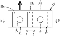
- FIG. 8 shows a schematic partial structure diagram of another second air circulation system in a cabinet provided by an embodiment of the present application
- FIG. 9 shows a cross-sectional view in the direction DD in FIG. 8
- the system includes a limiting shell 29, an air supply component 23c, a first air inlet structure, a second air intake structure and an air outlet structure.
- the limiting shell 29 has a first limiting wall 29a and a second limiting wall 29b arranged oppositely.
- the selection of the air supply part 23c can refer to the same structure of the air supply part 23a mentioned above, such as selecting a centrifugal fan, the air supply part 23c is arranged between the first limit wall 29a and the second limit wall 29b, It can be switched between the first position K1 and the second position K2 along the PQ direction, and the air inlet of the air supply member 23c faces the first limiting wall 29a.
- the first limiting wall 29a has vents d5 and d6 distributed side by side along the PQ direction, wherein the vent d5 communicates with the external space through the first air intake structure, and the vent d6 communicates with the cabinet through the second intake structure.
- the air inlet of the air supply member 23c and the ventilation port d5 are oppositely arranged and communicated.
- the air inlet of the air supply component 23c is arranged opposite to and communicated with the ventilation opening d6, so that the air inlet of the second air circulation system can be selectively It communicates with the external space or the second space of the cabinet.
- the top of the limiting shell 29 has an air outlet, and the air outlet on the top of the limiting shell communicates with the external space through the air outlet structure, and the air outlet structure exchanges heat with the first air circulation system through the heat exchange structure.
- the air inlet of the second air circulation system is switched in the external space or the second space, and replaced by Slide the air supply component in the linear direction to switch the air inlet of the second air circulation system in the external space or the second space.
- FIG. 10 shows a schematic partial structure diagram of another second air circulation system in a cabinet provided by an embodiment of the present application.
- the second air circulation system includes an air supply component 23d, an air collecting hood R1, and a first air inlet.
- the structure G1, the second air inlet structure G2 and the air outlet structure G3, the air supply component 23d can be a centrifugal fan or an axial flow fan, and the air outlets of the first air inlet structure G1 and the second air inlet structure G2 are exemplary It is connected with the air inlet of the air collecting hood R1, the air outlet mask of the air collecting hood R1 is on the air inlet of the air supply part 23d, and the air outlet of the air supply part 23d is communicated with the external space through the air outlet structure G3, and the air outlet The structure R1 exchanges heat with the first air circulation system.
- the first air inlet structure G1, the second air inlet structure G2 and the air outlet structure G3 are in the form of pipes, and the first air inlet structure G1 and the second air inlet structure G2 are respectively provided with a valve F1 and a valve F2, In order to control the on-off of the first air intake structure G1 and the second air intake structure G2 respectively.
- the air outlet of the air supply part 23d is communicated with the external space through the first air inlet structure G1; when the valve F1 is closed and the valve F2 is opened, the air outlet of the air supply part 23d passes through the second air inlet structure G1 communicates with the second space of the cabinet; or, valve F1 and valve F1 are opened at the same time, and the air outlet of the air supply component 23d communicates with the external space and the second space at the same time.
- the first air inlet structure, the second air inlet structure and the air outlet structure can also be in the form of the structure with the same name mentioned above, and the first air circulation system also has the function of controlling the first air inlet structure.
- a first switch (such as the aforementioned valve F1, or a wind deflector that can be inserted into the first air intake structure) for on-off of the wind structure, and a second switch (such as the aforementioned valve F2, or , which can be inserted into the wind deflector in the second wind inlet structure).
- a first switch such as the aforementioned valve F1, or a wind deflector that can be inserted into the first air intake structure
- a second switch (such as the aforementioned valve F2, or , which can be inserted into the wind deflector in the second wind inlet structure).
- the second air circulation system has a first air intake structure and a second air intake structure, and the first air intake structure and the second air intake structure respectively supply air to the air supply assembly to control the first air intake structure.
- the air inlet of the two-air circulation system draws air from the external space or the second space, or simultaneously draws air from the external space and the second space. But this is only an example, as long as the air outlet of the second air circulation system can be communicated with the external space, and the air inlet of the second air circulation system can optionally be communicated with the external space and/or the second space.
- each air supply component in the air supply assembly is still communicated with the external space through the air outlet structure, and the air inlet of each air supply component in at least some of the air supply components is communicated with one end of the hose, and the other end of the hose is connected to the air inlet.
- the air inlet can be selectively exposed to the external space or inserted into the second space according to requirements.
- the air supply component may not only be disposed outside the air duct, but also may be disposed inside one or several air ducts, and may also drive the airflow to flow in the corresponding directions in the foregoing embodiments.
- an embodiment of the present application further provides a heat exchange module, which is applied to the cabinet provided by any of the foregoing embodiments.
- the heat exchange module has a first air circulation system and a second air circulation system for exchanging heat with the first air circulation system; wherein, the air inlet and the air outlet of the first air circulation system are both used for connecting with the first air circulation system of the cabinet.
- the space is communicated; the air outlet of the second air circulation system is communicated with the external space, and the air inlet of the second air circulation system can optionally be used to communicate with the external space or the second space of the cabinet, or, simultaneously with the first space and The second space is connected.
- the first air circulation system includes an air duct T5, an air supply part 25a and an air duct T4, and the air supply part T5 drives the air in the first space S1 to enter the air duct T4 through the air duct T5, and passes through the air duct T4.
- the evaporator 24 returns to the first space S1 after cooling down.
- the second air circulation system includes an air duct T1, an air duct T2, an air supply part 23a and an air duct T3. By turning over the air supply part 23a, the air supply part 23a can be selected to enter the air from the external space or from the second space.
- the air discharged from the air supply part 23a reaches the air duct T3, and the air in the air duct T3 cools the condenser 22, and the condenser 22 and the evaporator 24 are connected by liquid pipes for heat exchange, so as to realize the first air circulation system and the second air circulation system.
- the heat exchange of the two-air circulation system This is only an example, for other possible implementations of the heat exchange module, reference may be made to the specific form of the heat exchange module 20 in the cabinet provided in any of the foregoing embodiments.
Landscapes
- Engineering & Computer Science (AREA)
- Microelectronics & Electronic Packaging (AREA)
- Chemical & Material Sciences (AREA)
- Combustion & Propulsion (AREA)
- Mechanical Engineering (AREA)
- General Engineering & Computer Science (AREA)
- Physics & Mathematics (AREA)
- Thermal Sciences (AREA)
- Aviation & Aerospace Engineering (AREA)
- Cooling Or The Like Of Electrical Apparatus (AREA)
Abstract
La présente invention concerne un module d'échange de chaleur et une armoire. Le module d'échange de chaleur est utilisé dans l'armoire. L'armoire comprend un corps d'armoire. Le corps d'armoire est pourvu d'un premier espace et d'un second espace. La température dans le premier espace est supérieure à la température dans le second espace. Le module d'échange de chaleur est pourvu d'un premier système de circulation d'air et d'un second système de circulation d'air. Un échange de chaleur est réalisé entre le premier système de circulation d'air et le second système de circulation d'air. Une entrée et une sortie du premier système de circulation d'air sont utilisées pour communiquer avec le premier espace, et une sortie du second système de circulation d'air est en communication avec un espace externe, et une entrée du second système de circulation d'air est utilisée de façon sélective pour communiquer avec l'espace externe et/ou le second espace. En fonction des exigences de dissipation de chaleur du premier espace et du second espace, l'extraction d'air par l'entrée du second système de circulation d'air depuis l'espace externe et/ou le second espace est sélectionnée. Au moyen du module d'échange de chaleur, la dissipation de la chaleur du premier espace et/ou du second espace est obtenue, et la flexibilité est élevée.
Priority Applications (4)
| Application Number | Priority Date | Filing Date | Title |
|---|---|---|---|
| EP20945299.4A EP4181641A4 (fr) | 2020-07-15 | 2020-07-15 | Module d'échange de chaleur et armoire |
| PCT/CN2020/102216 WO2022011620A1 (fr) | 2020-07-15 | 2020-07-15 | Module d'échange de chaleur et armoire |
| CN202080005747.XA CN114424682B (zh) | 2020-07-15 | 2020-07-15 | 一种换热模块及机柜 |
| US18/152,276 US12516833B2 (en) | 2020-07-15 | 2023-01-10 | Heat exchange module and cabinet |
Applications Claiming Priority (1)
| Application Number | Priority Date | Filing Date | Title |
|---|---|---|---|
| PCT/CN2020/102216 WO2022011620A1 (fr) | 2020-07-15 | 2020-07-15 | Module d'échange de chaleur et armoire |
Related Child Applications (1)
| Application Number | Title | Priority Date | Filing Date |
|---|---|---|---|
| US18/152,276 Continuation US12516833B2 (en) | 2020-07-15 | 2023-01-10 | Heat exchange module and cabinet |
Publications (1)
| Publication Number | Publication Date |
|---|---|
| WO2022011620A1 true WO2022011620A1 (fr) | 2022-01-20 |
Family
ID=79555924
Family Applications (1)
| Application Number | Title | Priority Date | Filing Date |
|---|---|---|---|
| PCT/CN2020/102216 Ceased WO2022011620A1 (fr) | 2020-07-15 | 2020-07-15 | Module d'échange de chaleur et armoire |
Country Status (4)
| Country | Link |
|---|---|
| US (1) | US12516833B2 (fr) |
| EP (1) | EP4181641A4 (fr) |
| CN (1) | CN114424682B (fr) |
| WO (1) | WO2022011620A1 (fr) |
Cited By (1)
| Publication number | Priority date | Publication date | Assignee | Title |
|---|---|---|---|---|
| CN119403100A (zh) * | 2024-12-31 | 2025-02-07 | 深圳科士达科技股份有限公司 | 充电模块 |
Families Citing this family (1)
| Publication number | Priority date | Publication date | Assignee | Title |
|---|---|---|---|---|
| CN215819125U (zh) * | 2021-01-15 | 2022-02-11 | 华为数字能源技术有限公司 | 一种温控机柜及通信系统 |
Citations (8)
| Publication number | Priority date | Publication date | Assignee | Title |
|---|---|---|---|---|
| CN1170482A (zh) * | 1994-12-14 | 1998-01-14 | 艾利森电话股份有限公司 | 安装在机壳或类似装置中的电信设备冷却系统 |
| CN101403522A (zh) * | 2008-10-29 | 2009-04-08 | 深圳市生瑞科技有限公司 | 一种高效换热通讯机柜及通讯机柜的高效换热方法 |
| CN101584261A (zh) * | 2006-12-01 | 2009-11-18 | 雷希尔有限公司 | 具有通气系统的设备柜 |
| CN101634477A (zh) * | 2008-07-25 | 2010-01-27 | 华为技术有限公司 | 一种热交换器及通信装置 |
| JP2010243069A (ja) * | 2009-04-07 | 2010-10-28 | Panasonic Corp | 熱交換装置とそれを用いた発熱体収納装置 |
| CN108092490A (zh) * | 2018-01-15 | 2018-05-29 | 天津瑞能电气有限公司 | 一种分区散热的功率柜 |
| CN207948008U (zh) * | 2018-03-23 | 2018-10-09 | 深圳市英维克科技股份有限公司 | 一种户外用分仓式独立温控机柜 |
| CN109688764A (zh) * | 2018-12-21 | 2019-04-26 | 华为数字技术(苏州)有限公司 | 机柜 |
Family Cites Families (21)
| Publication number | Priority date | Publication date | Assignee | Title |
|---|---|---|---|---|
| US3559728A (en) * | 1968-11-29 | 1971-02-02 | Kooltronic Fan Co | Electronic equipment rack temperature control |
| JP3432740B2 (ja) * | 1998-02-27 | 2003-08-04 | 大和ハウス工業株式会社 | 室内空調システム、同システムを用いた室内空調方法及び空調ユニット |
| US6164369A (en) * | 1999-07-13 | 2000-12-26 | Lucent Technologies Inc. | Door mounted heat exchanger for outdoor equipment enclosure |
| US6684653B2 (en) * | 2001-11-21 | 2004-02-03 | Nicholas H. Des Champs | Air-conditioner and air-to-air heat exchange for closed loop cooling |
| CN100516670C (zh) | 2003-03-25 | 2009-07-22 | 乐金电子(天津)电器有限公司 | 空调机 |
| CN1852648A (zh) * | 2006-02-24 | 2006-10-25 | 华为技术有限公司 | 机柜温控系统、装置及方法 |
| US20100018683A1 (en) | 2008-07-23 | 2010-01-28 | Tai-Her Yang | Double flow-circuit heat exchange device for periodic positive and reverse directional pumping |
| CN101754647B (zh) * | 2008-12-19 | 2012-03-21 | 华为技术有限公司 | 具有热交换的电子设备以及用于电子设备散热的系统 |
| CN201541419U (zh) | 2009-09-24 | 2010-08-04 | 建准电机工业股份有限公司 | 散热装置 |
| CN201536316U (zh) * | 2009-09-30 | 2010-07-28 | 艾默生网络能源有限公司 | 一种户外电源柜 |
| TWI426860B (zh) * | 2009-11-20 | 2014-02-11 | Delta Electronics Inc | 熱交換裝置及應用熱交換裝置的密閉式電器設備 |
| US9326426B2 (en) * | 2011-10-05 | 2016-04-26 | Diversified Control, Inc. | Equipment enclosure with air diverter temperature control system |
| CN202603129U (zh) * | 2012-05-17 | 2012-12-12 | 艾默生网络能源有限公司 | 一种机柜散热系统 |
| US10451295B2 (en) * | 2014-12-22 | 2019-10-22 | Diversified Control, Inc. | Equipment enclosure with multi-mode temperature control system |
| DE102015105490B3 (de) * | 2015-04-10 | 2016-08-04 | Rittal Gmbh & Co. Kg | Kühlgerät für die Kühlung der im Innenraum eines Schaltschranks aufgenommenen Luft und eine entsprechende Schaltschrankanordnung |
| TWI615089B (zh) * | 2016-04-08 | 2018-02-11 | 台達電子工業股份有限公司 | 電信機櫃及其熱交換器與其熱交換器組設方法 |
| CN107461836B (zh) * | 2016-06-02 | 2019-03-08 | 腾讯科技(深圳)有限公司 | 室外用模块化制冷模组及其安装方法 |
| CN106931518A (zh) * | 2017-04-13 | 2017-07-07 | 张永旺 | 一种独立双循环空气净化装置及其智能控制方法 |
| CN107084466A (zh) * | 2017-04-20 | 2017-08-22 | 森德(中国)暖通设备有限公司 | 新风换气机 |
| WO2019118352A1 (fr) * | 2017-12-11 | 2019-06-20 | Schlumberger Technology Corporation | Entraînement à fréquence variable refroidi par air |
| EP3723462B1 (fr) * | 2019-04-09 | 2022-06-22 | Pfannenberg GmbH | Système de refroidissement, en particulier pour armoires électroniques et armoire électronique doté d'un système de refroidissement |
-
2020
- 2020-07-15 WO PCT/CN2020/102216 patent/WO2022011620A1/fr not_active Ceased
- 2020-07-15 EP EP20945299.4A patent/EP4181641A4/fr active Pending
- 2020-07-15 CN CN202080005747.XA patent/CN114424682B/zh active Active
-
2023
- 2023-01-10 US US18/152,276 patent/US12516833B2/en active Active
Patent Citations (8)
| Publication number | Priority date | Publication date | Assignee | Title |
|---|---|---|---|---|
| CN1170482A (zh) * | 1994-12-14 | 1998-01-14 | 艾利森电话股份有限公司 | 安装在机壳或类似装置中的电信设备冷却系统 |
| CN101584261A (zh) * | 2006-12-01 | 2009-11-18 | 雷希尔有限公司 | 具有通气系统的设备柜 |
| CN101634477A (zh) * | 2008-07-25 | 2010-01-27 | 华为技术有限公司 | 一种热交换器及通信装置 |
| CN101403522A (zh) * | 2008-10-29 | 2009-04-08 | 深圳市生瑞科技有限公司 | 一种高效换热通讯机柜及通讯机柜的高效换热方法 |
| JP2010243069A (ja) * | 2009-04-07 | 2010-10-28 | Panasonic Corp | 熱交換装置とそれを用いた発熱体収納装置 |
| CN108092490A (zh) * | 2018-01-15 | 2018-05-29 | 天津瑞能电气有限公司 | 一种分区散热的功率柜 |
| CN207948008U (zh) * | 2018-03-23 | 2018-10-09 | 深圳市英维克科技股份有限公司 | 一种户外用分仓式独立温控机柜 |
| CN109688764A (zh) * | 2018-12-21 | 2019-04-26 | 华为数字技术(苏州)有限公司 | 机柜 |
Non-Patent Citations (1)
| Title |
|---|
| See also references of EP4181641A4 * |
Cited By (1)
| Publication number | Priority date | Publication date | Assignee | Title |
|---|---|---|---|---|
| CN119403100A (zh) * | 2024-12-31 | 2025-02-07 | 深圳科士达科技股份有限公司 | 充电模块 |
Also Published As
| Publication number | Publication date |
|---|---|
| US12516833B2 (en) | 2026-01-06 |
| EP4181641A1 (fr) | 2023-05-17 |
| EP4181641A4 (fr) | 2023-08-16 |
| US20230167991A1 (en) | 2023-06-01 |
| CN114424682B (zh) | 2025-09-12 |
| CN114424682A (zh) | 2022-04-29 |
Similar Documents
| Publication | Publication Date | Title |
|---|---|---|
| KR102173373B1 (ko) | 공기조화기 | |
| WO2020025043A1 (fr) | Système de climatisation de cuisine | |
| TWI405945B (zh) | 氣冷式熱交換器及其適用之電子設備 | |
| KR102609407B1 (ko) | 차량용 공조장치 및 그 제어방법 | |
| CN115789798A (zh) | 电控盒及空气源热泵空调 | |
| CN110043986A (zh) | 一种空调系统及采用其的数据中心 | |
| EP3879949B1 (fr) | Armoire de machine | |
| US12516833B2 (en) | Heat exchange module and cabinet | |
| CN206846992U (zh) | 多层机房散热系统 | |
| GB2572563A (en) | Modular air conditioning unit | |
| CN210980123U (zh) | 一种空调室外机 | |
| CN216620062U (zh) | 一体式空调器 | |
| JP3160838U (ja) | 放熱装置 | |
| CN115789797A (zh) | 电控盒及空气源热泵空调 | |
| CN114245679A (zh) | 空调器及其控制方法 | |
| CN220156945U (zh) | 散热组件、电控盒及空调器 | |
| CN110657527A (zh) | 一种厨房空调装置 | |
| JP2001263721A (ja) | 空気調和機 | |
| JP4195651B2 (ja) | 冷暖房換気システム | |
| CN207113141U (zh) | 温控系统及空调 | |
| CN219961223U (zh) | 一种冷却设备和数据中心 | |
| CN219876615U (zh) | 一种散热装置及数据中心冷却系统 | |
| CN106196329A (zh) | 窗机空调 | |
| CN110594921A (zh) | 智能型冷热风机 | |
| CN222165210U (zh) | 用于嵌入式制冷设备的半导体制冷装置和嵌入式制冷设备 |
Legal Events
| Date | Code | Title | Description |
|---|---|---|---|
| 121 | Ep: the epo has been informed by wipo that ep was designated in this application |
Ref document number: 20945299 Country of ref document: EP Kind code of ref document: A1 |
|
| NENP | Non-entry into the national phase |
Ref country code: DE |
|
| ENP | Entry into the national phase |
Ref document number: 2020945299 Country of ref document: EP Effective date: 20230213 |
|
| WWG | Wipo information: grant in national office |
Ref document number: 202080005747.X Country of ref document: CN |