WO2022014018A1 - Système de commande de bande, procédé de commande de bande, programme de commande de bande et terminal de ligne optique - Google Patents
Système de commande de bande, procédé de commande de bande, programme de commande de bande et terminal de ligne optique Download PDFInfo
- Publication number
- WO2022014018A1 WO2022014018A1 PCT/JP2020/027718 JP2020027718W WO2022014018A1 WO 2022014018 A1 WO2022014018 A1 WO 2022014018A1 JP 2020027718 W JP2020027718 W JP 2020027718W WO 2022014018 A1 WO2022014018 A1 WO 2022014018A1
- Authority
- WO
- WIPO (PCT)
- Prior art keywords
- report
- optical network
- unit
- value
- station
- Prior art date
- Legal status (The legal status is an assumption and is not a legal conclusion. Google has not performed a legal analysis and makes no representation as to the accuracy of the status listed.)
- Ceased
Links
Images



Classifications
-
- H—ELECTRICITY
- H04—ELECTRIC COMMUNICATION TECHNIQUE
- H04L—TRANSMISSION OF DIGITAL INFORMATION, e.g. TELEGRAPHIC COMMUNICATION
- H04L12/00—Data switching networks
- H04L12/28—Data switching networks characterised by path configuration, e.g. LAN [Local Area Networks] or WAN [Wide Area Networks]
- H04L12/44—Star or tree networks
Definitions
- the present disclosure relates to a bandwidth control system, a bandwidth control method, a bandwidth control program, and an optical network unit in a station.
- the in-station optical terminal device accommodates multiple optical network units (ONU: Optical) by time division multiplexing (TDM: Time Division Multiplexing). May be done.
- a PON Passive Optical Network
- GE-PON Gigabit Ethernet PON (Ethernet is a registered trademark)
- DBA Dynamic Bandwidth Allocation
- MPCP Multi Point Control Protocol
- DBA dynamic bandwidth allocation
- the purpose is to secure the data transmission time within the DBA cycle while responding to fluctuations in the amount of traffic requested by the home optical termination device, and to improve the bandwidth utilization efficiency. It is an object of the present invention to provide a control system, a band control method, a band control program, and an in-station optical termination device.
- the band control system is a communication system for communicating an optical signal between an in-station optical termination device and a plurality of in-home optical termination devices, wherein the plurality of in-home optical termination devices are reports from the in-station optical termination device.
- the report information is transmitted to the in-station optical termination device according to the request, and the in-station optical termination device transmits data from each of the plurality of home optical termination devices to the in-station optical termination device based on the report information.
- the station optical termination device includes a report value determination unit that determines a report value for each of the plurality of home optical termination devices based on the report information received in the past, and the above-mentioned.
- the band for transmitting data from each of the plurality of home optical termination devices to the in-station optical termination device is allocated for each preset band allocation cycle.
- An evaluation unit that calculates an evaluation value for each of the allocation unit and the home optical termination device based on the report information received in the past, and a plurality of evaluation units based on the evaluation value calculated by the evaluation unit.
- the report request determination unit includes a report request determination unit that determines whether or not to transmit the report request to each of the home optical termination devices, and when the report request determination unit determines to transmit the report request, the report request. Is determined as either a first report request for transmitting the report information at the report transmission time within the band allocation cycle or a second report request for transmitting the report information at the data transmission time within the band allocation cycle. do.
- the band control method is a communication system in which an optical signal is communicated between an in-station optical termination device and a plurality of in-home optical termination devices.
- the report information is transmitted to the in-station optical termination device according to the request, and the in-station optical termination device transmits data from each of the plurality of home optical termination devices to the in-station optical termination device based on the report information.
- the band for transmitting data from each of the plurality of home optical termination devices to the station optical termination device is allocated for each preset band allocation cycle.
- the report request determination step comprises a report request determination step for determining whether or not to transmit the report request to each of the plurality of home optical termination devices, and the report request determination step determines to transmit the report request.
- the report request includes a first report request for transmitting the report information at the report transmission time within the band allocation cycle and a second report request for transmitting the report information at the data transmission time within the band allocation cycle. Includes a step to determine one of.
- the band control program is a communication system for communicating an optical signal between an in-station optical termination device and a plurality of in-home optical termination devices, wherein the plurality of in-home optical termination devices are from the in-station optical termination device.
- the report information is transmitted to the in-station optical termination device according to the report request, and the in-station optical termination device transmits data from each of the plurality of home optical termination devices to the in-station optical termination device based on the report information.
- a plurality of the in-house optical termination devices are used for each preset band allocation cycle.
- Each of the plurality of home optical termination devices is evaluated based on the allocation step for allocating the band for transmitting data from each of the internal optical termination devices to the in-station optical termination device and the report information received in the past by the in-station optical termination device.
- An evaluation step for calculating a value, and a report request determination step for determining whether or not to send the report request to each of the plurality of home optical termination devices based on the evaluation value calculated in the evaluation step.
- the report request determination step determines to transmit the report request, the first report request for transmitting the report information at the report transmission time within the band allocation cycle, and the report request. It includes a step of determining one of the second report requests to transmit the report information at the data transmission time within the band allocation cycle.
- the in-station optical termination device is an in-station optical termination device that allocates a band for transmitting data from each of the plurality of in-home optical termination devices based on report information transmitted from the plurality of in-home optical termination devices. Therefore, based on the report value determination unit that determines the report value for each of the plurality of home optical termination devices based on the report information received in the past, and the report value determined by the report value determination unit. , Based on the allocation unit that allocates the band for transmitting data from each of the plurality of in-house optical termination devices to the in-station optical termination device for each preset band allocation cycle, and the report information received in the past.
- the evaluation unit that calculates the evaluation value for each of the plurality of home optical termination devices, and the report request is transmitted to each of the plurality of home optical termination devices based on the evaluation value calculated by the evaluation unit.
- the report request determination unit includes a report request determination unit that determines whether or not to send the report request, and when the report request determination unit determines to transmit the report request, the report request is sent to the report at the report transmission time within the band allocation cycle. It is determined to be either a first report request for transmitting information or a second report request for transmitting the report information within the data transmission time within the band allocation cycle.
- bandwidth control system bandwidth control method, bandwidth control program, and in-station optical network unit according to the present disclosure, the data transmission time within the DBA cycle while responding to fluctuations in the amount of traffic requested by the home optical network unit. It is possible to secure the above, and it is possible to improve the bandwidth utilization efficiency.
- FIG. 1 It is a figure which shows typically the whole structure of the communication system to which the band control system which concerns on Embodiment 1 is applied. It is a block diagram which shows the structure of the in-station optical network unit of the band control system which concerns on Embodiment 1. FIG. It is a flow diagram which shows an example of the operation of the band control system which concerns on Embodiment 1. FIG. It is a figure explaining an example of the operation of the band control system which concerns on Embodiment 1. FIG.
- FIG. 1 is a diagram schematically showing an overall configuration of a communication system to which a bandwidth control system is applied.
- FIG. 2 is a block diagram showing a configuration of an in-station optical network unit of a band control system.
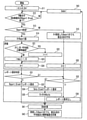
- FIG. 3 is a flow chart showing an example of the operation of the bandwidth control system.
- FIG. 4 is a diagram illustrating an example of the operation of the bandwidth control system.
- the communication system to which the band control system according to this embodiment is applied is a communication system that communicates an optical signal between the in-station optical terminal device 100 and a plurality of in-home optical terminal devices 20.
- the communication system includes an in-station optical network unit 100 and a plurality of in-home optical network units 20.
- the side of the in-station optical network unit 100 may be referred to as "upstream side", and the side of the home optical network unit 20 may be referred to as "downstream side”.
- the in-station optical terminal device 100 is communicably connected to each of the plurality of in-house optical terminal devices 20 via the optical branching unit 10.
- the communication network configured as described above is a so-called PON (Passive Optical Network).
- the optical network unit 100 in the station is communicably connected to the upstream external network 1.
- Each of the plurality of home optical network units 20 is communicably connected to the downstream external network 2.
- the optical signal transmitted from the in-station optical terminating device 100 is branched at the optical branching unit 10 and sent to each of the plurality of in-house optical terminating devices 20.
- the optical signals transmitted from each of the plurality of in-house optical terminal devices 20 are combined by the optical branching unit 10 and reach the in-station optical terminal device 100.
- a band is allocated to each of the plurality of home optical network units 20. This avoids signal collision after the combined wave at the optical branch portion 10.
- the band allocation at this time is performed by temporally separating the data transmission from each of the plurality of home optical network units 20 to the station optical network unit 100. That is, the band allocation referred to in the present disclosure is to allocate the time for permitting data transmission from each of the plurality of home optical network units 20 to the station optical network unit 100.
- the band allocation is dynamically performed according to the amount of data transmitted from each of the plurality of home optical network units 20 to the in-station optical network unit 100 (hereinafter, also referred to as “traffic amount”). It is done in. It can be said that the traffic volume of each of the plurality of home optical network units 20 is the amount of uplink data stored in the buffer of each home optical network unit 20. That is, in the communication network of this embodiment, dynamic bandwidth allocation (DBA: Dynamic Bandwidth Allocation) is adopted.
- DBA Dynamic Bandwidth Allocation
- the station optical network unit 100 transmits a report request to each of the plurality of home optical network units 20.
- Each of the plurality of home optical network units 20 transmits report information to the station optical network unit 100 in accordance with a report request from the station optical network unit 100.
- the report information from the home optical network unit 20 includes information regarding the amount of traffic requested by the home optical network unit 20.
- the station optical network unit 100 sets a band for transmitting data from each of the plurality of home optical network units 20 to the station optical network unit 100 based on the received report information from each of the home optical network units 20. assign.
- the in-station optical network unit 100 includes a PON unit 101, a report receiving unit 111, a DBA calculation unit 112, a Gate generation unit 113, a report value determination unit 121, an evaluation unit 122, and a report request determination unit 123. ing.
- the optical network unit 100 in the station includes a computer having a processor and a memory as hardware.
- the processor is also referred to as a CPU (Central Processing Unit), a central processing unit, a processing unit, an arithmetic unit, a microprocessor, a microcomputer, or a DSP.
- Examples of the memory include non-volatile or volatile semiconductor memories such as RAM, ROM, flash memory, EPROM and EEPROM, or magnetic disks, flexible disks, optical disks, compact disks, mini disks and DVDs.
- the program as software is stored in the memory of the optical network unit 100 in the station. Then, the in-station optical termination device 100 executes a preset process by executing a program stored in the memory by the processor, and as a result of the cooperation between the hardware and the software, the PON unit 101 and the report receiving unit
- the functions of 111, the DBA calculation unit 112, the Gate generation unit 113, the report value determination unit 121, the evaluation unit 122, and the report request determination unit 123 are realized.
- the PON unit 101 has a function of transmitting / receiving data transmitted / received to / from the upstream external network 1 to / from each of a plurality of home optical network units 20.
- the report receiving unit 111 extracts report information from the data transmitted from the plurality of home optical network units 20 and received by the PON unit 101 of the station optical network unit 100.
- the report information extracted by the report receiving unit 111 is stored in, for example, the memory of the optical network unit 100 in the station.
- the report value determination unit 121 determines the report value for each of the plurality of home optical network units 20 based on the report information extracted by the report reception unit 111.
- the report information extracted by the report receiving unit 111 can be rephrased as the report information received in the past by the optical network unit 100 in the station.
- the report value is the traffic volume of the home optical network unit 20 determined based on the report information. The details of the report value determination by the report value determination unit 121 will be described later.
- the DBA calculation unit 112 is an allocation unit that allocates a band when data is transmitted from each of the plurality of home optical network units 20 to the station optical network unit 100 based on the report value determined by the report value determination unit 121. ..
- the DBA calculation unit 112 allocates a band for each DBA cycle.
- the DBA cycle is a preset band allocation cycle.
- the report information from the home optical network unit 20 is transmitted every DBA cycle. Therefore, the report value determination unit 121 determines the report value for each DBA cycle. Then, the DBA calculation unit 112 allocates the band for each DBA cycle based on the report value. In allocating the band, the DBA calculation unit 112 calculates the data transmission start time and the transmission continuation time for each of the plurality of home optical network units 20. Then, the DBA calculation unit 112 generates Grant information including the calculated transmission start time and transmission duration.
- the Gate generation unit 113 generates a Gate frame including the Grant information generated by the DBA calculation unit.
- the Gate frame is a kind of control frame defined by MPCP (Multipoint Control Protocol).
- MPCP Multipoint Control Protocol
- the Gate frame generated by the Gate generation unit 113 is transmitted by the PON unit 101 to each of the plurality of home optical network units 20.
- the MPCP Report frame is used to transmit the report information from the home optical network unit 20 to the station optical network unit 100.
- the home optical network unit 20 that has received the Gate frame transmits data to the in-station optical network unit 100 according to the Grant information included in the Gate frame. In this way, each of the plurality of home optical network units 20 transmits data to the in-station optical network unit 100 according to the band (time) allocated for each DBA cycle.
- the evaluation unit 122 calculates an evaluation value for each of the plurality of home optical terminal devices based on the report information extracted by the report receiving unit 111, that is, the report information received by the station optical network unit 100 in the past. Then, the report request determination unit 123 determines whether or not to transmit a report request to each of the plurality of home optical network units 20 based on the evaluation value calculated by the evaluation unit 122. The evaluation unit 122 calculates an evaluation value for each DBA cycle. Then, the report request determination unit 123 determines whether or not to transmit a report request to each of the plurality of home optical network units 20 for each DBA cycle.
- the DBA cycle which is the bandwidth allocation cycle, is divided into a report transmission time and a data transmission time.
- the report transmission time is a time zone in which the home optical network unit 20 transmits report information.
- the data transmission time is a time zone in which the home optical network unit 20 mainly transmits data.
- the report request determination unit 123 of this embodiment determines that the report request is to be transmitted, the report request to be transmitted is determined to be either the first report request or the second report request.
- the first report request is a report request for causing the home optical network unit 20 to transmit report information at the report transmission time within the DBA cycle.
- the second report request is a report request for causing the home optical network unit 20 to transmit report information at the data transmission time within the DBA cycle.
- the Gate generation unit 113 generates a Gate frame including a report request according to the determination content of the report request determination unit 123.
- the Gate frame including the report request generated by the Gate generation unit 113 is transmitted by the PON unit 101 to each of the plurality of home optical network units 20.
- each of the plurality of in-house optical network units 20 transmits report information to the in-station optical network unit 100 in accordance with a report request from the in-station optical network unit 100. That is, the home optical network unit 20 that has received the first report request transmits the report information at the report transmission time within the next DBA cycle. Further, the home optical network unit 20 that has received the second report request transmits the report information at the data transmission time within the next DBA cycle. In this case, the home optical network unit 20 superimposes the report information on the data and transmits it. Then, the home optical network unit 20 that has not received the report request does not transmit the report information in the next DBA cycle.
- the report information may be transmitted from the home optical network unit 20 or the report information may not be transmitted from the home optical network unit 20.
- the report value determination unit 121 determines the amount of traffic included in the report information received by the station optical network unit 100.
- the report value is 20.
- the report value determination unit 121 determines the in-house optical that the in-house optical terminating device 100 has received in the past.
- the report value of the home optical network unit 20 is determined based on the traffic volume included in the report information of the terminal device 20. In this case, specifically, the report value determination unit 121 averages the amount of traffic included in the report information received in the most recent n times (n is a preset integer of 2 or more) for the home optical network unit 20.
- the value shall be the report value of the home optical network unit 20.
- the report information received by the home optical network unit 20 is extracted by the report receiving unit 111 and stored in, for example, the memory of the station optical network unit 100. Then, the report value determination unit 121 determines the report value based on the report information extracted by the report reception unit 111. In order to enable the report value determining unit 121 to calculate the average value for the latest n times, the in-station optical terminal device 100 stores the report information for the latest n times for each of the plurality of in-house optical terminal devices 20.
- the evaluation unit 122 uses two evaluation values, a first evaluation value i and a second evaluation value k.
- the first evaluation value i is an evaluation value calculated based on the fluctuation of the report value of the report information.
- the second evaluation value k is an evaluation value that changes depending on whether or not the in-station optical network unit 100 has received the report information.
- the initial values of the first evaluation value i and the second evaluation value k are both 0.
- the evaluation unit 122 calculates the first evaluation value i.
- the evaluation unit 122 first determines whether or not the fluctuation of the report value of the report information is equal to or less than the fluctuation standard. Whether or not the fluctuation of the report value of the report information is equal to or less than the fluctuation standard is determined, for example, by determining whether or not the following equation (1) holds.
- R (j, N) is a report value of the report information transmitted from the j-th home optical network unit 20 in the Nth cycle (N is an integer of 1 or more).
- a serial number is assigned to each of the plurality of home optical network units 20 in advance.
- Rave is an average value of report values of report information received in the last n times (n is a preset integer of 2 or more) for the j-th home optical network unit 20.
- s is the standard deviation of the report value of the report information received in the last n times for the j-th home optical network unit 20.
- the evaluation unit 122 may evaluate the fluctuation of the report value by using another index representing the variation of the report value instead of the standard deviation s. For example, when the variance s ⁇ 2 of the report value of the report information received in the last n times is used as an index instead of the standard deviation s, the evaluation unit 122 determines whether or not the following equation (2) holds. Therefore, it may be determined whether or not the fluctuation of the report value of the report information is equal to or less than the fluctuation standard.
- the evaluation unit 122 determines that the fluctuation of the report value of the report information is equal to or less than the fluctuation standard. Then, when it is determined that the fluctuation of the report value of the report information is equal to or less than the fluctuation standard, the evaluation unit 122 adds 1 to the first evaluation value i. On the other hand, if the equation (1) is not satisfied, the evaluation unit 122 determines that the fluctuation of the report value of the report information is not equal to or less than the fluctuation standard. Then, when it is determined that the fluctuation of the report value of the report information is not equal to or less than the fluctuation standard, the evaluation unit 122 subtracts 1 from the first evaluation value i. However, the first evaluation value i shall not be 0 or less.
- the second evaluation value k will be described.
- the evaluation unit 122 sets the second evaluation value k to the same value as the first evaluation value i.
- the evaluation unit 122 subtracts 1 from the second evaluation value k.
- the report request determination unit 123 determines to transmit the first report request for the home optical network unit 20 having the first evaluation value i of 0.
- the evaluation value in which the first evaluation value i is 0 corresponds to the case where the fluctuation of the report value of the report information is not equal to or less than the fluctuation standard. That is, the report request determination unit 123 determines the report request as the first report request when the evaluation value corresponds to the case where the fluctuation of the report value of the report information is not equal to or less than the fluctuation standard.
- the report request determination unit 123 determines to transmit the second report request for the home optical network unit 20 having the first evaluation value i of 1 or more and the second evaluation value k of 1 or less.
- the evaluation value in which the first evaluation value i is 1 or more corresponds to the case where the fluctuation of the report value of the report information is equal to or less than the fluctuation standard. That is, the report request determination unit 123 determines the report request as the second report request when the fluctuation of the report value of the report information is equal to or less than the fluctuation standard and the evaluation value corresponds to it.
- the report request determination unit 123 determines that the report request is not transmitted to the home optical network unit 20 whose first evaluation value i is 1 or more and whose second evaluation value k is more than 1.
- the evaluation value in which the second evaluation value k exceeds 1 corresponds to the case where the report information in which the fluctuation of the report value is equal to or less than the fluctuation standard is received at least twice. That is, the report request determination unit 123 determines that the report request is not transmitted when the evaluation value corresponds to the report information whose fluctuation of the report value is equal to or less than the fluctuation standard at least twice.
- the report transmission time and the data transmission time of the DBA cycle are referred to as Report Block and Data Block, respectively. Further, the process shown in FIG. 3 is performed for each of the plurality of home optical network units 20.
- step S11 the evaluation unit 122 initializes each of the first evaluation value i and the second evaluation value k to 0. Further, the in-station optical network unit 100 initializes the variable N for counting the number of the target DBA cycle to 1.
- step S12 the optical network unit 100 in the station waits until the Report Block in the current DBA cycle, that is, the Nth DBA cycle is completed, and when the Report Block is completed, the process proceeds to step S13.
- step S13 the report receiving unit 111 is between the end of the Report Block of the (N-1) th DBA cycle (the previous DBA cycle) and the end of the Report Block of the Nth DBA cycle (current DBA cycle). , It is determined whether or not the in-station optical network unit 100 has received report information about the home optical network unit 20. When the station optical network unit 100 has received report information about the home optical network unit 20, the report receiving unit 111 extracts the report information from the data received by the PON unit 101 of the station optical network unit 100. , The process proceeds to step S14. In step S14, the report value determination unit 121 sets the traffic amount of the report information received by the in-station optical network unit 100 in the current DBA cycle as the report value R of the home optical network unit 20.
- step S15 the report value determination unit 121 calculates the average value of the latest n times of the traffic volume included in the report information received in the past for the home optical network unit 20 as the report value R of the home optical network unit 20. And.
- step S21 the evaluation unit 122 makes an evaluation using the above-mentioned equation (1). Then, when the equation (1) is satisfied, the process proceeds to step S22. In step S22, the evaluation unit 122 adds 1 to the first evaluation value i. On the other hand, if the equation (1) is not satisfied in step S21, the process proceeds to step S23. In step S22, the evaluation unit 122 sets the larger of the value obtained by subtracting 1 from the first evaluation value i and 0 as the first evaluation value i. After step S22 or S23, the process proceeds to step S24. In step S24, the evaluation unit 122 sets the second evaluation value k to a value equal to the first evaluation value i updated in step S22 or S23.
- step S15 the process proceeds to step S25.
- step S25 the evaluation unit 122 subtracts 1 from the second evaluation value k.
- step S31 the report request determination unit 123 determines whether the first evaluation value i is 0 or 1 or more. When the first evaluation value i is 0, the process proceeds to step S32. In step S32, the report request determination unit 123 determines the transmission of the first report request to the home optical network unit 20. That is, the report information is transmitted by Report Block for the home optical network unit 20.
- step S31 determines whether the first evaluation value i is 1 or more in step S31. Further, even after step S25, the process proceeds to step S33.
- step S33 the report request determination unit 123 determines whether the second evaluation value k is 1 or less or greater than 1. If the second evaluation value k is 1 or less, the process proceeds to step S34.
- step S34 the report request determination unit 123 determines the transmission of the second report request to the home optical network unit 20. That is, the report information is transmitted by Data Block for the home optical network unit 20.
- the report value determination unit 121 adds 84 [byte] to the report value R of the home optical network unit 20. This 84 [byte] is the sum of the data size of the report information and the minimum value of the Ethernet (registered trademark) preamble / IFG.
- step S36 the report request determination unit 123 determines that the report request is not transmitted to the home optical network unit 20. Therefore, the transmission of report information from the home optical network unit 20 in the next DBA cycle is skipped.
- step S41 the DBA calculation unit 112 calculates the bandwidth allocation based on the report value R determined in steps S14, S15 or S35.
- step S42 the evaluation unit 122 calculates the mean value and standard deviation of the report values to be used for the evaluation in the next DBA cycle.
- step S43 the process proceeds to step S43, and 1 is added to the count variable N of the DBA cycle. Then, when the process of step S43 is completed, the process returns to step S12, and the intra-station optical network unit 100 performs the same process for the next DBA cycle.
- steps S14 and S15 correspond to the report value determination step.
- the report value determination step is a step of determining a report value for each of the plurality of home optical network units 20 based on the report information received in the past by the station optical network unit 100.
- Step S41 corresponds to the allocation step.
- data is transmitted from each of the plurality of home optical network units 20 to the station optical network unit 100 at each preset band allocation cycle based on the report value determined in the report value determination step. This is the step of allocating bandwidth.
- steps S21 to S25 correspond to evaluation steps.
- the evaluation step is a step of calculating an evaluation value for each of the plurality of home optical network units 20 based on the report information received in the past by the station optical network unit 100.
- Steps S31 to S36 correspond to the report request determination step.
- the report request determination step is a step of determining whether or not to send a report request to each of the plurality of home optical network units 20 based on the evaluation value calculated in the evaluation step. Then, in the report request determination step, the first report request for transmitting the report information at the report transmission time within the bandwidth allocation cycle and the second report request for transmitting the report information at the data transmission time within the bandwidth allocation cycle. Includes steps S32 and S34 to determine in any of the above.
- the computer of the in-station optical network unit 100 is programmed into the PON unit 101, the report receiving unit 111, the DBA calculation unit 112, the Gate generation unit 113, and the report. It functions as each part of the value determination unit 121, the evaluation unit 122, and the report request determination unit 123.
- This program is a bandwidth control program for operating a bandwidth control system. Further, this program is also a band control program for causing the computer of the local optical network unit 100 to execute the band control method as described above. Then, this band control program causes the computer of the optical network unit 100 in the station to execute each step of the report value determination step, the allocation step, the evaluation step, and the report request determination step described above.
- the report transmission time and the data transmission time of the DBA cycle are described as Report Block and Data Block, respectively.
- OLT in the figure is an abbreviation for Optical Line Thermal, and corresponds to an optical network unit 100 in a station.
- ONU in the figure is an abbreviation for Optical Network Unit and corresponds to an optical network unit 20 in the house.
- the first evaluation value i and the second evaluation value k are 0.
- the first report request is transmitted from the in-station optical network unit 100 to the home optical network unit 20, so that the home optical network unit 20 is a report block.
- Send report information The optical network unit 100 in the station generates Grant information based on the received report information. Further, the optical network unit 100 in the station evaluates the report value of the received report information, and determines whether or not the report request is transmitted and whether the report request is the first report request or the second report request.
- the first evaluation value i becomes 0.
- the first report request is transmitted to the home optical network unit 20 having the first evaluation value i of 0.
- 1 is added to the first evaluation value i and the first evaluation value i becomes 1 or more.
- a second report request is transmitted to the home optical network unit 20 having a first evaluation value i of 1 or more and a second evaluation value k of 1 or less.
- the report request is not transmitted to the home optical network unit 20 having a first evaluation value i of 1 or more and a second evaluation value k of more than 1.
- the second evaluation value k is first set to the first evaluation value i when the station optical network unit 100 receives the report information, and then is subtracted by 1 each time the transmission of the report information is skipped. .. Therefore, in order for the transmission of the report information to be skipped, it is necessary for the optical network unit 100 in the station to receive the report information whose fluctuation of the report value is equal to or less than the fluctuation reference at least twice.
- the Grant information and the report request are transmitted from the in-station optical network unit 100 to each of the home optical network unit 20 in the Gate frame. Further, in the Data Block, each of the in-house optical terminal devices 20 transmits data to the in-station optical network unit 100 according to the band allocation (DBA cycle 1 in the figure).
- each of the home optical network units 20 transmits report information to the station optical network unit 100 according to the received report request. Specifically, the home optical network unit 20 that has received the first report request transmits the report information by Report Block. Further, the home optical network unit 20 that has received the second report request transmits the report information by superimposing it on the data in the band allocated in the Data Block. Then, the home optical network unit 20 that has not received the report request does not transmit the report information.
- the report information is not sent in the next DBA cycle, so that the station optical network unit 100 receives the report information from the home optical network unit 20. Is not received, and the evaluation unit 122 subtracts 1 from the second evaluation value k. Therefore, the second evaluation value k will eventually become 1 or less, and the second report request will be transmitted from the in-station optical network unit 100 to the in-house optical network unit 20. Therefore, in the next DBA cycle, the data transmission time (Data Block) will be used. Report information transmission will be resumed.
- Data Block Data Block
- the home optical termination device 20 is evaluated based on the report information received in the past, and the report value, that is, the in-home optical termination device 100 is evaluated.
- the report information is superimposed on the data at the data transmission time within the DBA cycle and transmitted.
- the fluctuation of the report value, that is, the traffic amount requested by the home optical network unit 20 is stable in a small state, the transmission of the report information is skipped. Therefore, the band required for report transmission can be narrowed down within the DBA cycle, and the band utilization efficiency can be improved by allocating that amount to the band for data transmission.
- the report value is calculated by averaging the traffic volume of the report information received in the past.
- the fluctuation of the report value is small, so that the bandwidth can be allocated more accurately by the report value calculated in this way.
- the first evaluation value i may be set to 0 in step S23 of FIG. Therefore, in this modification, when the fluctuation of the report value becomes larger than the fluctuation standard, the first evaluation value i becomes 0 and the first report request is sent to the home optical network unit 20, so that the report is reported in the next DBA cycle. Report information will be sent at the sending time.
- the present disclosure can be used for a band control system, a band control method, a band control program, and an in-station optical end device applied to a communication system for communicating an optical signal between an in-station optical end device and a plurality of in-house optical end devices. ..
- Upstream external network 2 Downstream external network 10
- Optical branch 20 In-house optical network unit 100
- In-station optical network unit 101 PON unit 111
- Report receiving unit 112 DBA calculation unit 113
- Report value determination unit 122 Evaluation unit 123 Report request Judgment unit
Landscapes
- Engineering & Computer Science (AREA)
- Computer Networks & Wireless Communication (AREA)
- Signal Processing (AREA)
- Small-Scale Networks (AREA)
Abstract
L'invention concerne un système de commande de bande et autres pouvant améliorer l'efficacité d'utilisation de bande dans un système de communication pour effectuer une attribution de bande passante dynamique en fonction de quantités de trafic. Pour cela, un terminal de ligne optique du système de commande de bande comprend : une unité de détermination de valeur de rapport qui détermine une valeur de rapport pour une unité de réseau optique sur la base d'informations de rapport reçues ; une unité d'attribution qui attribue, sur la base de la valeur de rapport, une bande à utiliser lorsque des données sont transmises à partir de l'unité de réseau optique dans chaque période d'attribution de bande ; une unité d'évaluation qui calcule une valeur d'évaluation pour l'unité de réseau optique sur la base des informations de rapport reçues ; et une unité de décision de demande de rapport qui détermine, sur la base de la valeur d'évaluation, s'il faut transmettre ou non une demande de rapport à l'unité de réseau optique. L'unité de décision de demande de rapport détermine, en tant que demande de rapport à transmettre, soit une première demande de rapport pour amener les informations de rapport à être transmises à un instant de transmission de rapport dans la période d'attribution de bande soit une seconde demande de rapport pour amener les informations de rapport à être transmises à un instant de transmission de données dans la période d'attribution de bande.
Priority Applications (2)
| Application Number | Priority Date | Filing Date | Title |
|---|---|---|---|
| PCT/JP2020/027718 WO2022014018A1 (fr) | 2020-07-16 | 2020-07-16 | Système de commande de bande, procédé de commande de bande, programme de commande de bande et terminal de ligne optique |
| JP2022536075A JP7347677B2 (ja) | 2020-07-16 | 2020-07-16 | 帯域制御システム、帯域制御方法、帯域制御用プログラム及び局内光終端装置 |
Applications Claiming Priority (1)
| Application Number | Priority Date | Filing Date | Title |
|---|---|---|---|
| PCT/JP2020/027718 WO2022014018A1 (fr) | 2020-07-16 | 2020-07-16 | Système de commande de bande, procédé de commande de bande, programme de commande de bande et terminal de ligne optique |
Publications (1)
| Publication Number | Publication Date |
|---|---|
| WO2022014018A1 true WO2022014018A1 (fr) | 2022-01-20 |
Family
ID=79554612
Family Applications (1)
| Application Number | Title | Priority Date | Filing Date |
|---|---|---|---|
| PCT/JP2020/027718 Ceased WO2022014018A1 (fr) | 2020-07-16 | 2020-07-16 | Système de commande de bande, procédé de commande de bande, programme de commande de bande et terminal de ligne optique |
Country Status (2)
| Country | Link |
|---|---|
| JP (1) | JP7347677B2 (fr) |
| WO (1) | WO2022014018A1 (fr) |
Citations (5)
| Publication number | Priority date | Publication date | Assignee | Title |
|---|---|---|---|---|
| JP2009278165A (ja) * | 2008-05-12 | 2009-11-26 | Mitsubishi Electric Corp | 光通信システム |
| WO2014178375A1 (fr) * | 2013-05-02 | 2014-11-06 | 三菱電機株式会社 | Dispositif station parent, dispositif station enfant, système de communication optique, dispositif de contrôle, et procédé d'allocation de bande passante |
| JP2015033051A (ja) * | 2013-08-05 | 2015-02-16 | 住友電気工業株式会社 | 動的帯域割当方法、局側装置、コンピュータプログラム及びponシステム |
| US20150304046A1 (en) * | 2014-04-18 | 2015-10-22 | Broadcom Corporation | Probabilistic Bandwidth Control in a Passive Optical Network (PON) |
| JP2018082260A (ja) * | 2016-11-15 | 2018-05-24 | Kddi株式会社 | Ponシステムおよび伝送方法 |
-
2020
- 2020-07-16 WO PCT/JP2020/027718 patent/WO2022014018A1/fr not_active Ceased
- 2020-07-16 JP JP2022536075A patent/JP7347677B2/ja active Active
Patent Citations (5)
| Publication number | Priority date | Publication date | Assignee | Title |
|---|---|---|---|---|
| JP2009278165A (ja) * | 2008-05-12 | 2009-11-26 | Mitsubishi Electric Corp | 光通信システム |
| WO2014178375A1 (fr) * | 2013-05-02 | 2014-11-06 | 三菱電機株式会社 | Dispositif station parent, dispositif station enfant, système de communication optique, dispositif de contrôle, et procédé d'allocation de bande passante |
| JP2015033051A (ja) * | 2013-08-05 | 2015-02-16 | 住友電気工業株式会社 | 動的帯域割当方法、局側装置、コンピュータプログラム及びponシステム |
| US20150304046A1 (en) * | 2014-04-18 | 2015-10-22 | Broadcom Corporation | Probabilistic Bandwidth Control in a Passive Optical Network (PON) |
| JP2018082260A (ja) * | 2016-11-15 | 2018-05-24 | Kddi株式会社 | Ponシステムおよび伝送方法 |
Also Published As
| Publication number | Publication date |
|---|---|
| JPWO2022014018A1 (fr) | 2022-01-20 |
| JP7347677B2 (ja) | 2023-09-20 |
Similar Documents
| Publication | Publication Date | Title |
|---|---|---|
| KR100415584B1 (ko) | 비동기 전송 모드 수동 광통신망(atm-pon)상에서의동적 대역 할당 방법 | |
| CA2714025C (fr) | Procede d'attribution de largeur de bande et systeme de reseau optique passif | |
| CN101841745A (zh) | 光传送路终端装置、无源光网系统以及频带分配方法 | |
| EP1371189A4 (fr) | Procede et systeme d'allocation dynamique de bande passante dans un reseau d'acces optique | |
| CN114365459B (zh) | 网络控制装置、通信资源分配方法以及通信系统 | |
| CN114868363B (zh) | 光通信装置以及资源管理方法 | |
| WO2014178375A1 (fr) | Dispositif station parent, dispositif station enfant, système de communication optique, dispositif de contrôle, et procédé d'allocation de bande passante | |
| CN111901706B (zh) | 一种tdm pon中的onu发现测距方法和系统 | |
| JPWO2010092667A1 (ja) | 親局装置およびグラント割り当て方法 | |
| JP5702867B2 (ja) | 波長帯域割当方法 | |
| CN117729461A (zh) | 单帧多突发的配置方法、装置、电子设备及存储介质 | |
| KR20020011026A (ko) | 수동광분기망에서 맥을 위한 승인 요청 방법 | |
| US11412316B2 (en) | Optical line terminal and bandwidth allocation method | |
| JP7347677B2 (ja) | 帯域制御システム、帯域制御方法、帯域制御用プログラム及び局内光終端装置 | |
| JP5487003B2 (ja) | 光端局装置、光通信システム及び動的帯域割当方法 | |
| JP2019022196A (ja) | 光通信システム | |
| JP2019036859A (ja) | 光通信装置、光通信方法、光通信プログラム、及び光通信システム | |
| JP2020136986A (ja) | 光通信システム、局側装置および加入者側装置、光通信システムの波長切替方法、ならびに、局側装置および加入者側装置の波長切替プログラム | |
| JP5563376B2 (ja) | 光通信システム及び光通信方法 | |
| US20250338048A1 (en) | Olt and pon system | |
| JP4877483B2 (ja) | 送信割当て方法及び装置 | |
| JP6861593B2 (ja) | 加入者線端局装置 | |
| JP7063349B2 (ja) | リソース割当装置、リソース割当プログラム、リソース割当方法及び局側装置 | |
| JP7366314B2 (ja) | 局側装置、光通信システム、帯域割当方法、制御回路および記憶媒体 | |
| JP2012151577A (ja) | Ponシステム及び帯域割り当て方法 |
Legal Events
| Date | Code | Title | Description |
|---|---|---|---|
| 121 | Ep: the epo has been informed by wipo that ep was designated in this application |
Ref document number: 20945369 Country of ref document: EP Kind code of ref document: A1 |
|
| ENP | Entry into the national phase |
Ref document number: 2022536075 Country of ref document: JP Kind code of ref document: A |
|
| NENP | Non-entry into the national phase |
Ref country code: DE |
|
| 122 | Ep: pct application non-entry in european phase |
Ref document number: 20945369 Country of ref document: EP Kind code of ref document: A1 |