WO2022014095A1 - イオンセンサの製造方法およびイオンセンサ用電極体 - Google Patents
イオンセンサの製造方法およびイオンセンサ用電極体 Download PDFInfo
- Publication number
- WO2022014095A1 WO2022014095A1 PCT/JP2021/009783 JP2021009783W WO2022014095A1 WO 2022014095 A1 WO2022014095 A1 WO 2022014095A1 JP 2021009783 W JP2021009783 W JP 2021009783W WO 2022014095 A1 WO2022014095 A1 WO 2022014095A1
- Authority
- WO
- WIPO (PCT)
- Prior art keywords
- ion
- electrode body
- sensitive film
- manufacturing
- ion sensor
- Prior art date
- Legal status (The legal status is an assumption and is not a legal conclusion. Google has not performed a legal analysis and makes no representation as to the accuracy of the status listed.)
- Ceased
Links
Images




Classifications
-
- G—PHYSICS
- G01—MEASURING; TESTING
- G01N—INVESTIGATING OR ANALYSING MATERIALS BY DETERMINING THEIR CHEMICAL OR PHYSICAL PROPERTIES
- G01N27/00—Investigating or analysing materials by the use of electric, electrochemical, or magnetic means
- G01N27/26—Investigating or analysing materials by the use of electric, electrochemical, or magnetic means by investigating electrochemical variables; by using electrolysis or electrophoresis
- G01N27/28—Electrolytic cell components
- G01N27/30—Electrodes, e.g. test electrodes; Half-cells
- G01N27/333—Ion-selective electrodes or membranes
Definitions
- the present invention relates to a method for manufacturing an ion sensor and an electrode body for an ion sensor.
- the ion sensor is used together with the reference electrode to measure the concentration of ionic electrolytic substances in the sample, and is mounted on and used in analytical instruments such as clinical analyzers, water quality analyzers, soil analyzers, and food analyzers.
- the ion-sensitive film formed on the sensitive surface of the ion sensor has traditionally been based on a hydrophobic organic polymer such as polyvinyl chloride, which contains dibutyl phthalate (DBP), dipropyl phthalate (DPP), orthonitrophenyl.
- a hydrophobic organic polymer such as polyvinyl chloride, which contains dibutyl phthalate (DBP), dipropyl phthalate (DPP), orthonitrophenyl.
- DBP dibutyl phthalate
- DPP dipropyl phthalate
- NPOE octyl ether
- an organic polymer that is the base of the ion-sensitive film and a solvent solution in which an ion-sensitive substance is dissolved in a volatile solvent in a predetermined ratio are applied to the sensitive surface of the ion sensor by brushing, dipping, and dropping. It is produced by first forming a coating film of the solution by applying it by means of the like, and then advancing the evaporation of the solvent while applying stress in the sensitive surface direction. In this way, when the solvent is evaporated while applying stress, an ion-sensitive film with an extremely smooth surface can be obtained as compared with the case of simple coating and drying, and an ion sensor that greatly suppresses the adverse effects of adhesion of proteins and the like can be obtained. Obtainable.
- the ion sensor is generally composed of an electrode body, an internal solution, an ion-sensitive film, and an internal electrode (for example, Patent Document 1).
- the electrode body of the flow-type ion sensor has a sample flow path, and a through hole is provided on a part of the side surface of the sample flow path. Then, the through hole is covered with the ion-sensitive film to form a response surface, and the ion-sensitive film and the electrode body are adhered to each other at a position other than the response surface.
- the organic polymer constituting the ion-sensitive film and the electrode body is once dissolved in a volatile solvent such as tetrahydrofuran (THF) at the bonding interface, and then the volatile solvent is applied. It is done by evaporating.
- a volatile solvent such as tetrahydrofuran (THF)
- An object of the present invention is to provide an ion sensor manufacturing method and an ion sensor electrode body with few performance defects by improving the adhesive strength between the electrode body and the ion sensitive film regardless of material variation.
- the present invention is a method for manufacturing an ion sensor in which an ion-sensitive film is adhered to an electrode body provided with an internal electrode while accommodating an internal solution.
- the electrode body for an ion sensor is provided with an internal electrode that outputs a potential generated in the ion-sensitive film and an electrode body that houses an internal solution that electrically conducts the internal electrode and the ion-sensitive film.
- the electrode body has a flow path through which a liquid containing a sample to be measured flows, and a mounting surface on which the ion-sensitive film is placed.
- a penetrating portion is formed which is exposed to bring the sample into contact with the ion-sensitive membrane, and in a state where water is present in the above-mentioned mounting surface other than the penetrating portion, pressurization and laser are performed from above the ion-sensitive membrane. By irradiating with light, the ion-sensitive film and the above-mentioned mounting surface are adhered to each other.
- the present invention it is possible to provide a method for manufacturing an ion sensor and an electrode body for an ion sensor, in which the adhesive strength between the electrode body and the ion-sensitive film is improved regardless of material variation and there are few performance defects.
- FIG. 1 is an overall view illustrating an outline of a manufacturing method of the ion sensor 1 according to the present embodiment.
- water 2 a laser irradiator 3, and a weight 4 are used.
- the wall surface on the front side is not shown, but this is for the sake of clarity, and in reality, a wall surface similar to the wall surface on the back side is provided.
- the electrode body for an ion sensor includes an internal electrode 14 that outputs a potential to the ion-sensitive film, an electrode body 5 that houses an internal solution (not shown) that electrically conducts the internal electrode 14 and the ion-sensitive film 10, and the inside. It includes an electrode body pin 15 for sealing the solution so as not to leak, and an electrode body plate 13 as a bottom surface for accommodating an internal container.
- the electrode body 5 has a sample flow path 7 formed inside the electrode body 5 through which a liquid containing a sample to be measured flows, and a mounting surface 9 (bonding surface) on which the ion-sensitive film 10 is placed.
- the electrode body 5 has a rectangular parallelepiped shape having external dimensions of about 11 mm ⁇ 20 mm ⁇ 24 mm, the sample flow path 7 has a diameter of about 1 mm, and the mounting surface 9 has a mounting surface of about 5 mm ⁇ 5 mm. Further, a part of the sample flow path 7 is exposed to the mounting surface 9 to bring the sample into contact with the ion-sensitive film 10, and an oval-shaped penetrating portion 8 having a size of about 0.9 mm ⁇ 3 mm is formed.
- the entire electrode body 5 is made of a thermoplastic resin or a hard resin containing a pigment.
- the pigment may be applied to the mounting surface 9 of the electrode body 5 separately from the electrode body main body made of a hard resin.
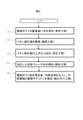
- FIG. 2 is a flowchart showing a manufacturing method of an ion sensor
- FIGS. 3 to 7 are diagrams illustrating each step in the manufacturing method of the ion sensor.
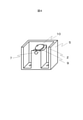
- FIG. 3 is a diagram showing a coating process in this step S1. Since the water applied to the mounting surface 9 is held on the surface of the mounting surface 9 by surface tension, it does not flow down from the penetrating portion 8 to the sample flow path.
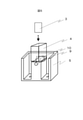
- FIG. 4 is a diagram showing the mounting process in step S2.
- the ion-sensitive film 10 is formed of a soft or hard resin material having a diameter of 5 mm and a thickness of about 0.1 mm to 0.5 mm. Further, the ion-sensitive film 10 transmits wavelengths in the far-infrared region and has a melting point higher than that of the electrode body 5 on the mounting surface 9.
- FIG. 5 is a diagram showing a pressurizing step in this step S3.
- a weight 4 is used, and the weight 4 sandwiches the water 2 and presses the ion-sensitive film 10 vertically against the mounting surface 9 of the electrode body 5.
- the material of the weight 4 may be ceramic or the like in addition to transparent glass such as quartz glass, but is not limited to these as long as it is a material that transmits a wavelength in the far infrared region.
- the lower end surface of the weight 4, which is the side in contact with the ion-sensitive film 10, is about the same size as the mounting surface 9 of the electrode body 5 and has a shape similar to that of the mounting surface 9.
- the force for pressurizing may be obtained by using not only the gravity of the weight 4 itself but also an external force such as a servomotor.
- step S4 the ion-sensitive film 10 is pressed against the mounting surface 9 and irradiated with laser light from above the ion-sensitive film 10 (opposite the electrode body 5) (step S4).
- FIG. 6 is a diagram showing an irradiation step in this step S4.
- the laser light is a wavelength in the far infrared region emitted from the laser irradiator 3, and when the entire mounting surface 9 or the entire weight 4 is irradiated, the energy of the laser light is converted into heat energy, and the electrode body 5 is subjected to heat energy.
- the mounting surface 9 melts due to heat generation.
- the irradiation time of the laser beam is about 1 second to 20 seconds in consideration of the time until the mounting surface 9 of the electrode body 5 melts and hardens.
- the irradiation step is performed while the pressurizing step of step S3 continues, and the ion-sensitive film 10 is pressed against the mounted surface 9 in a molten state, so that the ion-sensitive films 10 are easily adhered to each other. Further, by performing the pressurizing step for about 1 to 20 seconds even after the irradiation step is completed, the adhesive strength of the mounting surface 9 near the penetrating portion 8 with the ion-sensitive film 10 is improved.
- step S5 the final assembly step of the ion sensor 1 is started (step S5).
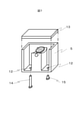
- FIG. 7 is a diagram showing the assembly process in step S5.
- this assembling step first, the electrode body plate 13 is adhered and fixed to the electrode body 5, and the internal solution is filled from the hole portion 12. Further, after inserting the internal electrode 14 from the hole portion 12 and adhesively fixing it to the electrode body 5, the electrode body pin 15 is inserted from the hole portion 12 and adhesively fixed to the electrode body 5. This completes the production of the ion sensor 1.
- FIG. 8 is a diagram showing the state of the facing surface between the electrode body 5 and the ion-sensitive film 10 when the ion-sensitive film 10 is pressed by the weight 4, and FIG. 8A shows water 2 as a comparative example. If not, (b) is the case where water 2 is used as in the present embodiment.
- the case where the material of the electrode body 5 varies and the mounting surface 9 has irregularities will be described as an example, but the same applies when the material of the ion-sensitive film 10 varies.
- the gap between the electrode body 5 and the ion-sensitive film 10 is filled with water 2, so that when the laser beam is irradiated, the thermal energy becomes one. It is transmitted like.
- the water 2 itself evaporates due to heat, melting on the mounting surface 9 of the electrode body 5 is evenly promoted, and the adhesion between the electrode body 5 and the ion-sensitive film 10 is improved.
- the adhesive strength between the electrode body 5 and the ion-sensitive film 10 becomes strong, so that performance defects due to peeling of the response surface can be suppressed. It is possible to obtain stable quality and a high yield rate.
- Electrode body pin 1: Ion sensor, 2: Water, 3: Laser irradiator, 4: Weight, 5: Electrode body, 7: Specimen flow path, 8: Penetration part, 9: Placement surface, 10: Ion sensitive film, 11: Gap , 12: Hole, 13: Electrode body plate, 14: Internal electrode, 15: Electrode body pin
Landscapes
- Chemical & Material Sciences (AREA)
- Life Sciences & Earth Sciences (AREA)
- Health & Medical Sciences (AREA)
- Physics & Mathematics (AREA)
- Chemical Kinetics & Catalysis (AREA)
- Electrochemistry (AREA)
- Molecular Biology (AREA)
- Analytical Chemistry (AREA)
- Biochemistry (AREA)
- General Health & Medical Sciences (AREA)
- General Physics & Mathematics (AREA)
- Immunology (AREA)
- Pathology (AREA)
- Investigating Or Analyzing Materials By The Use Of Electric Means (AREA)
- Measurement Of The Respiration, Hearing Ability, Form, And Blood Characteristics Of Living Organisms (AREA)
Abstract
Description
Claims (6)
- 内部溶液を収容するとともに内部電極を備える電極体に、イオン感応膜を接着させるイオンセンサの製造方法であって、
前記電極体のうち、前記イオン感応膜を載置する電極ボディの載置面に水を塗布する塗布工程と、
前記載置面に水が存在した状態で、前記イオン感応膜を載置する載置工程と、
前記イオン感応膜を、前記電極ボディの反対側から、加圧する加圧工程と、
前記イオン感応膜が前記電極ボディに押し付けられた状態で、前記電極ボディの反対側からレーザ光を照射する照射工程と、を有するイオンセンサの製造方法。 - 請求項1に記載のイオンセンサの製造方法において、
前記加圧工程では、前記レーザ光を透過する重りが用いられることを特徴とするイオンセンサの製造方法。 - 請求項1に記載のイオンセンサの製造方法において、
前記照射工程は、前記加圧工程が続いている間に行われることを特徴とするイオンセンサの製造方法。 - 請求項1に記載のイオンセンサの製造方法において、
前記電極ボディの載置面の融点は、前記イオン感応膜よりも低いことを特徴とするイオンセンサの製造方法。 - 請求項4に記載のイオンセンサの製造方法において、
前記電極ボディの載置面には、前記電極ボディの本体とは別の材料が設けられていることを特徴とするイオンセンサの製造方法。 - イオン感応膜に生じる電位を出力する内部電極と、前記内部電極と前記イオン感応膜を電気的に導通させる内部溶液を収容する電極ボディと、を備えたイオンセンサ用電極体であって、
前記電極ボディは、測定対象の検体を含む液体が流通する流路と、前記イオン感応膜を載せる載置面と、を有し、
前記流路の上面の所定位置には、前記載置面へ露出して前記検体を前記イオン感応膜と接触させる貫通部が形成されており、
前記載置面のうち前記貫通部以外に水が存在した状態で、前記イオン感応膜の上方から加圧およびレーザ光照射することにより、前記イオン感応膜と前記載置面とが接着されるイオンセンサ用電極体。
Priority Applications (4)
| Application Number | Priority Date | Filing Date | Title |
|---|---|---|---|
| CN202180039765.4A CN115698693B (zh) | 2020-07-16 | 2021-03-11 | 离子传感器的制造方法以及离子传感器用电极体 |
| JP2022536129A JP7408810B2 (ja) | 2020-07-16 | 2021-03-11 | イオンセンサの製造方法 |
| US18/015,636 US12429450B2 (en) | 2020-07-16 | 2021-03-11 | Method for manufacturing ion sensor, and electrode body for ion sensor |
| EP21842112.1A EP4184156A4 (en) | 2020-07-16 | 2021-03-11 | METHOD FOR PRODUCING AN ION SENSOR AND ELECTRODE BODY FOR AN ION SENSOR |
Applications Claiming Priority (2)
| Application Number | Priority Date | Filing Date | Title |
|---|---|---|---|
| JP2020-121933 | 2020-07-16 | ||
| JP2020121933 | 2020-07-16 |
Publications (1)
| Publication Number | Publication Date |
|---|---|
| WO2022014095A1 true WO2022014095A1 (ja) | 2022-01-20 |
Family
ID=79554691
Family Applications (1)
| Application Number | Title | Priority Date | Filing Date |
|---|---|---|---|
| PCT/JP2021/009783 Ceased WO2022014095A1 (ja) | 2020-07-16 | 2021-03-11 | イオンセンサの製造方法およびイオンセンサ用電極体 |
Country Status (5)
| Country | Link |
|---|---|
| US (1) | US12429450B2 (ja) |
| EP (1) | EP4184156A4 (ja) |
| JP (1) | JP7408810B2 (ja) |
| CN (1) | CN115698693B (ja) |
| WO (1) | WO2022014095A1 (ja) |
Cited By (2)
| Publication number | Priority date | Publication date | Assignee | Title |
|---|---|---|---|---|
| WO2025022941A1 (ja) | 2023-07-21 | 2025-01-30 | 株式会社日立ハイテク | イオンセンサ用電極体およびイオンセンサの製造方法 |
| WO2025197215A1 (ja) * | 2024-03-18 | 2025-09-25 | 株式会社日立ハイテク | フロー型イオン選択性電極の製造方法及びフロー型イオン選択性電極 |
Citations (9)
| Publication number | Priority date | Publication date | Assignee | Title |
|---|---|---|---|---|
| JPS559138A (en) * | 1978-07-07 | 1980-01-23 | Hitachi Ltd | Ion selective electrode |
| JPS59102153A (ja) * | 1982-12-06 | 1984-06-13 | Hitachi Ltd | イオン選択電極及びその製作方法 |
| JPS6010163A (ja) * | 1983-06-30 | 1985-01-19 | Toshiba Corp | 流通型イオンセンサ体 |
| JPH0729457U (ja) * | 1993-10-26 | 1995-06-02 | 株式会社島津製作所 | イオン選択性電極 |
| JPH095293A (ja) * | 1995-06-15 | 1997-01-10 | Horiba Ltd | イオン応答センサとその製造方法およびmosfetの製造方法 |
| JPH09210949A (ja) * | 1996-01-31 | 1997-08-15 | Miura Co Ltd | イオン電極の製造方法 |
| JPH11295261A (ja) * | 1998-04-14 | 1999-10-29 | Toshiba Corp | イオン選択性電極およびその製造方法 |
| KR100474880B1 (ko) * | 1997-01-24 | 2005-08-10 | 엘지전자 주식회사 | 고체형이온센서제조방법 |
| JP2018205034A (ja) * | 2017-05-31 | 2018-12-27 | 株式会社日立ハイテクノロジーズ | 陰イオン選択性電極及びその製造方法 |
Family Cites Families (7)
| Publication number | Priority date | Publication date | Assignee | Title |
|---|---|---|---|---|
| US4459199A (en) * | 1982-12-21 | 1984-07-10 | The Foxboro Company | Ruggedized ion-responsive electrode and its manufacturing process |
| CN1008181B (zh) * | 1984-09-05 | 1990-05-30 | 奥里安研究公司 | 关于改进的离子敏感电极 |
| US4687500A (en) * | 1984-09-05 | 1987-08-18 | Orion Research Inc. | Method for manufacturing an ion-sensitive electrode |
| JPH11132991A (ja) * | 1997-10-29 | 1999-05-21 | Hitachi Ltd | イオン選択性電極及びその製造方法 |
| JP2007049040A (ja) * | 2005-08-11 | 2007-02-22 | Omron Corp | 接合方法 |
| JP2009066820A (ja) | 2007-09-11 | 2009-04-02 | Kirin Brewery Co Ltd | 水を介在させたプラスチック部材のレーザー溶接方法 |
| JP2025102153A (ja) | 2023-12-26 | 2025-07-08 | ローム株式会社 | 表示装置及びソースドライバ |
-
2021
- 2021-03-11 US US18/015,636 patent/US12429450B2/en active Active
- 2021-03-11 EP EP21842112.1A patent/EP4184156A4/en active Pending
- 2021-03-11 CN CN202180039765.4A patent/CN115698693B/zh active Active
- 2021-03-11 JP JP2022536129A patent/JP7408810B2/ja active Active
- 2021-03-11 WO PCT/JP2021/009783 patent/WO2022014095A1/ja not_active Ceased
Patent Citations (9)
| Publication number | Priority date | Publication date | Assignee | Title |
|---|---|---|---|---|
| JPS559138A (en) * | 1978-07-07 | 1980-01-23 | Hitachi Ltd | Ion selective electrode |
| JPS59102153A (ja) * | 1982-12-06 | 1984-06-13 | Hitachi Ltd | イオン選択電極及びその製作方法 |
| JPS6010163A (ja) * | 1983-06-30 | 1985-01-19 | Toshiba Corp | 流通型イオンセンサ体 |
| JPH0729457U (ja) * | 1993-10-26 | 1995-06-02 | 株式会社島津製作所 | イオン選択性電極 |
| JPH095293A (ja) * | 1995-06-15 | 1997-01-10 | Horiba Ltd | イオン応答センサとその製造方法およびmosfetの製造方法 |
| JPH09210949A (ja) * | 1996-01-31 | 1997-08-15 | Miura Co Ltd | イオン電極の製造方法 |
| KR100474880B1 (ko) * | 1997-01-24 | 2005-08-10 | 엘지전자 주식회사 | 고체형이온센서제조방법 |
| JPH11295261A (ja) * | 1998-04-14 | 1999-10-29 | Toshiba Corp | イオン選択性電極およびその製造方法 |
| JP2018205034A (ja) * | 2017-05-31 | 2018-12-27 | 株式会社日立ハイテクノロジーズ | 陰イオン選択性電極及びその製造方法 |
Non-Patent Citations (1)
| Title |
|---|
| See also references of EP4184156A4 * |
Cited By (2)
| Publication number | Priority date | Publication date | Assignee | Title |
|---|---|---|---|---|
| WO2025022941A1 (ja) | 2023-07-21 | 2025-01-30 | 株式会社日立ハイテク | イオンセンサ用電極体およびイオンセンサの製造方法 |
| WO2025197215A1 (ja) * | 2024-03-18 | 2025-09-25 | 株式会社日立ハイテク | フロー型イオン選択性電極の製造方法及びフロー型イオン選択性電極 |
Also Published As
| Publication number | Publication date |
|---|---|
| JPWO2022014095A1 (ja) | 2022-01-20 |
| EP4184156A1 (en) | 2023-05-24 |
| US12429450B2 (en) | 2025-09-30 |
| EP4184156A4 (en) | 2024-08-21 |
| US20230314361A1 (en) | 2023-10-05 |
| CN115698693B (zh) | 2025-07-29 |
| JP7408810B2 (ja) | 2024-01-05 |
| CN115698693A (zh) | 2023-02-03 |
Similar Documents
| Publication | Publication Date | Title |
|---|---|---|
| US4222635A (en) | Method and apparatus for producing liquid crystal displays, and a liquid crystal display produced thereby | |
| JP7408810B2 (ja) | イオンセンサの製造方法 | |
| CN100580484C (zh) | 具有改进的密封结构的液体透镜 | |
| US8904627B2 (en) | Method for sealing package | |
| CN109239163B (zh) | 传感器 | |
| KR102608049B1 (ko) | 유리-플라스틱 연결부의 제조 방법 | |
| JP2018205290A (ja) | 蛍光x線分析装置用の試料ホルダ並びに試料ホルダ作成治具及び蛍光x線分析装置用の試料の作製方法 | |
| US20190250121A1 (en) | Ion-Selective Electrode, Test Specimen, and Analyzer | |
| US3700579A (en) | Apparatus for measuring the concentration of dissolved oxygen in an aqueous solution | |
| US10008690B2 (en) | Method and system of flattening a surface formed by sealant of packaging cover plate, and packaging method | |
| Li et al. | A novel spectroscopic method to image H2O distribution in ion-selective membranes | |
| JPWO2008078403A1 (ja) | 電気泳動チップ及びその使用方法 | |
| JPH0551861B2 (ja) | ||
| US3843506A (en) | Method of making internal half cell | |
| WO2025022941A1 (ja) | イオンセンサ用電極体およびイオンセンサの製造方法 | |
| US5223123A (en) | Method for making a polarographic oxygen sensor | |
| JP2003247942A (ja) | 硬化性接着剤組成物の硬化物の硬化レベルの非破壊検査方法及び電子装置の製造方法 | |
| JP4425891B2 (ja) | 細胞電気生理センサおよびその製造方法 | |
| JP2012237562A (ja) | 放射線検出パネルおよび放射線画像検出器 | |
| JP5559643B2 (ja) | 粉末試料の発光測定方法 | |
| JP2000055863A (ja) | フロータイプイオンセンサ、その電極用セル及びその製造方法 | |
| JP2022077851A5 (ja) | ||
| JP7863452B2 (ja) | 電気化学測定装置、電気化学センサ及び電気化学測定方法 | |
| KR102580372B1 (ko) | 레이저 가열용 파우치형 이차전지 씰링면 검사 지그 및 장치 | |
| JP3911206B2 (ja) | 分析セル、それを用いた質量分析装置、及び質量分析方法 |
Legal Events
| Date | Code | Title | Description |
|---|---|---|---|
| 121 | Ep: the epo has been informed by wipo that ep was designated in this application |
Ref document number: 21842112 Country of ref document: EP Kind code of ref document: A1 |
|
| ENP | Entry into the national phase |
Ref document number: 2022536129 Country of ref document: JP Kind code of ref document: A |
|
| NENP | Non-entry into the national phase |
Ref country code: DE |
|
| ENP | Entry into the national phase |
Ref document number: 2021842112 Country of ref document: EP Effective date: 20230216 |
|
| WWG | Wipo information: grant in national office |
Ref document number: 202180039765.4 Country of ref document: CN |
|
| WWG | Wipo information: grant in national office |
Ref document number: 18015636 Country of ref document: US |