WO2022014100A1 - ロータの製造方法およびロータ - Google Patents
ロータの製造方法およびロータ Download PDFInfo
- Publication number
- WO2022014100A1 WO2022014100A1 PCT/JP2021/011728 JP2021011728W WO2022014100A1 WO 2022014100 A1 WO2022014100 A1 WO 2022014100A1 JP 2021011728 W JP2021011728 W JP 2021011728W WO 2022014100 A1 WO2022014100 A1 WO 2022014100A1
- Authority
- WO
- WIPO (PCT)
- Prior art keywords
- shaft
- insertion hole
- laminated core
- rotor
- shaft insertion
- Prior art date
- Legal status (The legal status is an assumption and is not a legal conclusion. Google has not performed a legal analysis and makes no representation as to the accuracy of the status listed.)
- Ceased
Links
Images




Classifications
-
- H—ELECTRICITY
- H02—GENERATION; CONVERSION OR DISTRIBUTION OF ELECTRIC POWER
- H02K—DYNAMO-ELECTRIC MACHINES
- H02K15/00—Processes or apparatus specially adapted for manufacturing, assembling, maintaining or repairing of dynamo-electric machines
- H02K15/02—Processes or apparatus specially adapted for manufacturing, assembling, maintaining or repairing of dynamo-electric machines of stator or rotor bodies
- H02K15/03—Processes or apparatus specially adapted for manufacturing, assembling, maintaining or repairing of dynamo-electric machines of stator or rotor bodies having permanent magnets
-
- B—PERFORMING OPERATIONS; TRANSPORTING
- B21—MECHANICAL METAL-WORKING WITHOUT ESSENTIALLY REMOVING MATERIAL; PUNCHING METAL
- B21D—WORKING OR PROCESSING OF SHEET METAL OR METAL TUBES, RODS OR PROFILES WITHOUT ESSENTIALLY REMOVING MATERIAL; PUNCHING METAL
- B21D26/00—Shaping without cutting otherwise than using rigid devices or tools or yieldable or resilient pads, i.e. applying fluid pressure or magnetic forces
- B21D26/02—Shaping without cutting otherwise than using rigid devices or tools or yieldable or resilient pads, i.e. applying fluid pressure or magnetic forces by applying fluid pressure
- B21D26/033—Deforming tubular bodies
-
- B—PERFORMING OPERATIONS; TRANSPORTING
- B21—MECHANICAL METAL-WORKING WITHOUT ESSENTIALLY REMOVING MATERIAL; PUNCHING METAL
- B21D—WORKING OR PROCESSING OF SHEET METAL OR METAL TUBES, RODS OR PROFILES WITHOUT ESSENTIALLY REMOVING MATERIAL; PUNCHING METAL
- B21D26/00—Shaping without cutting otherwise than using rigid devices or tools or yieldable or resilient pads, i.e. applying fluid pressure or magnetic forces
- B21D26/02—Shaping without cutting otherwise than using rigid devices or tools or yieldable or resilient pads, i.e. applying fluid pressure or magnetic forces by applying fluid pressure
- B21D26/033—Deforming tubular bodies
- B21D26/047—Mould construction
-
- B—PERFORMING OPERATIONS; TRANSPORTING
- B21—MECHANICAL METAL-WORKING WITHOUT ESSENTIALLY REMOVING MATERIAL; PUNCHING METAL
- B21D—WORKING OR PROCESSING OF SHEET METAL OR METAL TUBES, RODS OR PROFILES WITHOUT ESSENTIALLY REMOVING MATERIAL; PUNCHING METAL
- B21D39/00—Application of procedures in order to connect objects or parts, e.g. coating with sheet metal otherwise than by plating; Tube expanders
- B21D39/06—Application of procedures in order to connect objects or parts, e.g. coating with sheet metal otherwise than by plating; Tube expanders of tubes in openings, e.g. rolling-in
-
- B—PERFORMING OPERATIONS; TRANSPORTING
- B21—MECHANICAL METAL-WORKING WITHOUT ESSENTIALLY REMOVING MATERIAL; PUNCHING METAL
- B21D—WORKING OR PROCESSING OF SHEET METAL OR METAL TUBES, RODS OR PROFILES WITHOUT ESSENTIALLY REMOVING MATERIAL; PUNCHING METAL
- B21D39/00—Application of procedures in order to connect objects or parts, e.g. coating with sheet metal otherwise than by plating; Tube expanders
- B21D39/08—Tube expanders
-
- B—PERFORMING OPERATIONS; TRANSPORTING
- B23—MACHINE TOOLS; METAL-WORKING NOT OTHERWISE PROVIDED FOR
- B23P—METAL-WORKING NOT OTHERWISE PROVIDED FOR; COMBINED OPERATIONS; UNIVERSAL MACHINE TOOLS
- B23P11/00—Connecting or disconnecting metal parts or objects by metal-working techniques not otherwise provided for
- B23P11/005—Connecting or disconnecting metal parts or objects by metal-working techniques not otherwise provided for by expanding or crimping
-
- B—PERFORMING OPERATIONS; TRANSPORTING
- B23—MACHINE TOOLS; METAL-WORKING NOT OTHERWISE PROVIDED FOR
- B23P—METAL-WORKING NOT OTHERWISE PROVIDED FOR; COMBINED OPERATIONS; UNIVERSAL MACHINE TOOLS
- B23P15/00—Making specific metal objects by operations not covered by a single other subclass or a group in this subclass
-
- H—ELECTRICITY
- H02—GENERATION; CONVERSION OR DISTRIBUTION OF ELECTRIC POWER
- H02K—DYNAMO-ELECTRIC MACHINES
- H02K1/00—Details of the magnetic circuit
- H02K1/06—Details of the magnetic circuit characterised by the shape, form or construction
- H02K1/22—Rotating parts of the magnetic circuit
- H02K1/27—Rotor cores with permanent magnets
- H02K1/2706—Inner rotors
- H02K1/272—Inner rotors the magnetisation axis of the magnets being perpendicular to the rotor axis
- H02K1/274—Inner rotors the magnetisation axis of the magnets being perpendicular to the rotor axis the rotor consisting of two or more circumferentially positioned magnets
- H02K1/2753—Inner rotors the magnetisation axis of the magnets being perpendicular to the rotor axis the rotor consisting of two or more circumferentially positioned magnets the rotor consisting of magnets or groups of magnets arranged with alternating polarity
- H02K1/276—Magnets embedded in the magnetic core, e.g. interior permanent magnets [IPM]
-
- H—ELECTRICITY
- H02—GENERATION; CONVERSION OR DISTRIBUTION OF ELECTRIC POWER
- H02K—DYNAMO-ELECTRIC MACHINES
- H02K1/00—Details of the magnetic circuit
- H02K1/06—Details of the magnetic circuit characterised by the shape, form or construction
- H02K1/22—Rotating parts of the magnetic circuit
- H02K1/28—Means for mounting or fastening rotating magnetic parts on to, or to, the rotor structures
-
- H—ELECTRICITY
- H02—GENERATION; CONVERSION OR DISTRIBUTION OF ELECTRIC POWER
- H02K—DYNAMO-ELECTRIC MACHINES
- H02K7/00—Arrangements for handling mechanical energy structurally associated with dynamo-electric machines, e.g. structural association with mechanical driving motors or auxiliary dynamo-electric machines
- H02K7/003—Couplings; Details of shafts
-
- B—PERFORMING OPERATIONS; TRANSPORTING
- B23—MACHINE TOOLS; METAL-WORKING NOT OTHERWISE PROVIDED FOR
- B23P—METAL-WORKING NOT OTHERWISE PROVIDED FOR; COMBINED OPERATIONS; UNIVERSAL MACHINE TOOLS
- B23P2700/00—Indexing scheme relating to the articles being treated, e.g. manufactured, repaired, assembled, connected or other operations covered in the subgroups
- B23P2700/12—Laminated parts
Definitions
- the present invention relates to a rotor manufacturing method and a rotor.
- Japanese Patent Application Laid-Open No. 2001-268858 discloses a rotor for a motor including a hollow rotating shaft having a pipe structure and a laminated iron core into which the rotating shaft is inserted.
- the rotating shaft is inserted into a through hole provided in the center of the laminated iron core.
- the rotating shaft is provided with a retaining portion formed by a hydroforming method.
- the retaining portion is formed by expanding the rotating shaft toward the outer diameter side by the hydroforming method. Further, the retaining portion is provided so as to sandwich the laminated iron core in the axial direction.
- the laminated iron core is formed by laminating a silicon steel plate provided with one key groove.
- the rotation shaft expands by the hydroforming method, so that a convex portion that meshes with the key groove is formed.
- the deviation of the laminated iron core with respect to the rotation axis in the rotation direction is suppressed.
- the present invention has been made to solve the above-mentioned problems, and one object of the present invention is to shift the laminated core in the rotation direction with respect to the shaft when the shaft is fixed to the laminated core by hydroforming. It is an object of the present invention to provide a rotor and a method for manufacturing the rotor, which can prevent the balance in the rotation of the rotor from being deteriorated while preventing the above.
- the method for manufacturing a rotor in the first aspect of the present invention comprises a laminated core including a shaft insertion hole into which a tubular shaft is inserted and a magnet insertion hole into which a permanent magnet is inserted.
- a method for manufacturing a rotor to be provided which is a distance between the apex of a shaft insertion hole provided in the center of the laminated core and having a non-circular shape including a plurality of apex and the outer peripheral surface of the shaft when viewed from the axial direction of the laminated core.
- the outer peripheral surface of the shaft is inside the shaft insertion hole when viewed from the axial direction by hydroforming, which is expanded by pressurizing the liquid filled inside the shaft. It comprises a fixing step of fixing the shaft to the laminated core by deforming it into a non-circular shape along the peripheral surface.
- the apex of the shaft insertion hole when viewed from the axial direction of the laminated core, the apex of the shaft insertion hole having a non-circular shape including a plurality of apex and the outer peripheral surface of the shaft
- a fixing step of fixing the shaft to the laminated core is performed by deforming the outer peripheral surface of the shaft into a non-circular shape along the inner peripheral surface of the shaft insertion hole when viewed from the axial direction.
- the rotor in the second aspect of the present invention comprises a tubular shaft, a permanent magnet, and a laminated core including a shaft insertion hole into which the shaft is inserted and a magnet insertion hole into which the permanent magnet is inserted.
- the shaft is fixed to the laminated core by hydroforming, which is expanded by pressurizing the liquid filled inside the shaft, and the shaft insertion hole is the center of the laminated core when viewed from the axial direction of the laminated core.
- the laminated core has a non-circular shape provided in the portion and includes a plurality of vertices, and the number of vertices and sides of the shaft insertion hole is an integral multiple of the number of poles, or the number of poles is a number of poles other than the number of poles. It is configured to be a number divided by an integer of.
- the shaft insertion hole has a non-circular shape including a plurality of vertices when viewed from the axial direction of the laminated core. This regulates the rotational deviation of the laminated core with respect to the shaft at each of the plurality of vertices.
- the laminated core is configured such that the number of vertices and sides of the shaft insertion hole is an integral multiple of the number of poles or the number of poles divided by a fraction of the number of poles other than the number of poles.
- the present invention it is possible to prevent the balance in the rotation of the rotor from being deteriorated while preventing the laminated core from being displaced with respect to the shaft in the rotation direction.
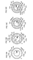
- FIG. 9 is a partially enlarged view of the vicinity of the magnetic pole forming portion of FIG. It is a flow figure which shows the manufacturing method of the rotor by 2nd Embodiment. It is a plan sectional view which shows the structure of the laminated core by the modification of 1st Embodiment. It is a plan sectional view which shows the structure of the laminated core by the modification of 2nd Embodiment.
- the "axial direction” means the direction along the rotation axis C of the rotor 1, and means the Z direction in the drawing. Further, the “diametrical direction” means the radial direction of the rotor 1 (R1 direction or R2 direction), and the “circumferential direction” means the circumferential direction of the rotor 1 (E1 direction or E2 direction).
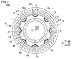
- the rotary electric machine 100 includes a rotor 1 and a stator 2. Further, the rotor 1 and the stator 2 are each formed in an annular shape. The rotor 1 is arranged so as to face the inside of the stator 2 in the radial direction. That is, in the first embodiment, the rotary electric machine 100 is configured as an inner rotor type rotary electric machine. Further, a shaft 3 is arranged inside the rotor 1 (rotor core 4) in the radial direction. The shaft 3 is connected to an engine, an axle, or the like via a rotational force transmitting member such as a gear.
- the rotary electric machine 100 is configured as a motor, a generator, or a motor / generator, and is configured to be mounted on a vehicle.
- the rotor 1 includes a rotor core 4.
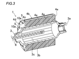
- the rotor core 4 includes a laminated core 4b in which a plurality of electrical steel sheets 4a (see FIG. 3) are laminated and have magnet insertion holes 10a extending in the stacking direction of the electrical steel sheets 4a.
- the rotor 1 (rotor core 4) includes a permanent magnet 5. The permanent magnet 5 is inserted (arranged) into the magnet insertion hole 10a of the laminated core 4b.
- a plurality of magnet insertion holes 10a (16 in the first embodiment) are provided in the laminated core 4b. That is, the rotary electric machine 100 is configured as an embedded permanent magnet type motor (IPM motor: International Permanent Magnet Motor).
- IPM motor International Permanent Magnet Motor
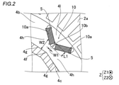
- the laminated core 4b has a magnetic pole including a pair of magnet insertion holes 10a adjacent to each other in the circumferential direction and a bridge portion 10b (see FIG. 2) arranged between the magnet insertion holes 10a of the pair of magnet insertion holes 10a.
- a plurality of magnetic pole forming portions 10 to be formed are included.
- the bridge portion 10b is provided so as to connect the radial inner portion 4h of the laminated core 4b and the radial outer portion 4l of the laminated core 4b.
- Eight magnetic pole forming portions 10 are provided in the laminated core 4b at equal angular intervals along the circumferential direction when viewed from the rotation axis C direction. Further, the pair of magnet insertion holes 10a in the magnetic pole forming portion 10 are arranged in a V shape.
- the bridge portion 10b is provided so as to connect a portion radially outside the magnet insertion hole 10a and a portion radially inside the magnet insertion hole 10a in the laminated core 4b. There is.
- the bridge portion 10b is provided so as to extend in the radial direction.
- the circumferential width W1 of the bridge portion 10b is smaller than the radial length L1 of the bridge portion 10b.
- the rotor core 4 is rotated around the rotation axis C.
- the rotor core 4 (laminated core 4b) includes a shaft insertion hole 4c provided in the central portion of the laminated core 4b when viewed from the axial direction of the laminated core 4b (viewed from the Z1 direction side).
- the shaft 3 is inserted into the shaft insertion hole 4c of the laminated core 4b.
- the rotational force of the shaft 3 is transmitted to the laminated core 4b, and the laminated core 4b is configured to rotate.
- the stator 2 includes a stator core 2a and a coil 2b wound (arranged) around the stator core 2a.
- the stator core 2a is arranged on the outer side in the radial direction of the rotor core 4.
- the stator core 2a is configured such that, for example, a plurality of electromagnetic steel sheets (silicon steel sheets) are laminated in the axial direction so that magnetic flux can pass through the stator core 2a.
- the coil 2b is connected to an external power supply unit and is configured to supply electric power (for example, three-phase alternating current electric power).
- the coil 2b is configured to generate a magnetic field by being supplied with electric power.
- the rotor 1 and the shaft 3 are configured to rotate with respect to the stator 2 as the engine or the like is driven, even when electric power is not supplied to the coil 2b.
- the coil 2b is arranged over the entire circumference of the stator core 2a.
- the permanent magnet 5 has a rectangular cross section orthogonal to the axial direction.
- the permanent magnet 5 is configured so that the magnetizing direction (magnetism direction) is the lateral direction.
- a resin material (not shown) for fixing the permanent magnet 5 arranged in the magnet insertion hole 10a is arranged.
- the shaft 3 is formed in a cylindrical shape.
- the shaft 3 is provided with an insertion hole 3a into which an oil injection portion 6 described later is inserted.
- the shaft 3 is fixed to the laminated core 4b by hydroforming, which is expanded by pressurizing the liquid 800 (see FIG. 8) filled inside the shaft 3.
- the shaft 3 includes a fixed portion 3b fixed to the laminated core 4b.
- the fixed portion 3b is the entire portion of the shaft 3 inserted into the shaft insertion hole 4c of the laminated core 4b.
- the rotor 1 is provided with an oil injection unit 6 which is inserted into the inside of the shaft 3 through the insertion hole 3a and injects cooling oil inside the shaft 3.
- the shaft insertion hole 4c has a non-circular shape including a plurality of vertices 4f when viewed from the axial direction.
- the shaft insertion hole 4c has a regular polygonal shape when viewed from the axial direction.
- the shaft insertion hole 4c has a regular hexadecagonal shape when viewed from the axial direction.
- the shaft insertion hole 4c may have a regular polygon (for example, a regular hexagon) other than a regular hexadecagon when viewed from the axial direction.
- the outer peripheral surface 3e (inner peripheral surface 3c) of the shaft 3 expanded by hydroforming has a regular hexadecagonal shape along the shaft insertion hole 4c of the rotor core 4 when viewed from the axial direction.
- the laminated core 4b is configured so that the number of the vertices 4f and the sides 4g of the shaft insertion hole 4c is an integral multiple of the number of poles.
- the number of poles (the number of magnetic pole forming portions 10) is eight, and the number of vertices 4f and sides 4g of the shaft insertion hole 4c is 16. That is, the number of vertices 4f and sides 4g of the shaft insertion hole 4c is twice the number of poles.
- the apex 4f of the shaft insertion hole 4c is a portion corresponding to an intersection of adjacent sides 4g, and is not necessarily a pin angle but may have a constant curvature. Further, the side 4g does not necessarily have to be a straight line, and may have a constant curvature.
- the apex 4f of the shaft insertion hole 4c overlaps the bridge portion 10b (all eight bridge portions 10b) of the magnetic pole forming portion 10 in the circumferential direction when viewed from the axial direction. It is configured to be placed in position.
- the apex 4f that does not overlap with the bridge portion 10b in the circumferential direction is arranged at a position that overlaps with the central portion in the circumferential direction of the magnetic pole forming portions 10 adjacent to each other in the circumferential direction.
- the apex 4f arranged at a position overlapping the bridge portion 10b in the circumferential direction is provided so as to overlap with the vicinity of the center in the circumferential direction of the bridge portion 10b in the circumferential direction.
- the laminated core 4b is configured such that the magnet insertion hole 10a is arranged at a position where the magnet insertion hole 10a overlaps with the side 4g of the shaft insertion hole 4c in the circumferential direction when viewed from the axial direction.
- a radial inner portion 4h having a width W2 in the radial direction is formed between the magnet insertion hole 10a and the side 4g. Since the pair of magnet insertion holes 10a have a V-shape, the width W2 gradually decreases toward the apex 4f side arranged at a position overlapping the bridge portion 10b in the circumferential direction.
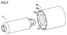
- step S1 a step of preparing the laminated core 4b and the shaft 3 is performed. Specifically, as shown in FIG. 5, a cylindrical shaft 3 and a laminated core 4b in which the shaft insertion hole 4c has a non-circular shape (regular hexadecagon) when viewed from the axial direction are prepared. At this point, the shaft 3 has a circular shape (see FIG. 7) when viewed from the axial direction.
- a non-circular shape regular hexadecagon
- the apex 4f of the shaft insertion hole 4c is arranged at a position where the apex 4f of the shaft insertion hole 4c overlaps the bridge portion 10b provided between the magnet insertion holes 10a adjacent to each other in the circumferential direction in the circumferential direction.
- the core forming step of forming the laminated core 4b is performed. Specifically, in the core forming step, when viewed from the axial direction, the apex 4f of the shaft insertion hole 4c is a magnet insertion hole 10a of a pair of magnet insertion holes 10a adjacent to each other in the circumferential direction in each of the plurality of magnetic pole forming portions 10.
- the laminated core 4b is provided between the laminated cores 4b so as to be arranged at a position overlapping with the bridge portion 10b that connects the radial outer portion 4l of the laminated core 4b and the radial inner portion 4h of the laminated core 4b. Is the process of forming.
- the core forming step performed in step S1 is an example of the "first core forming step" in the claims.
- step S2 an insertion step of inserting the shaft 3 into the shaft insertion hole 4c (see FIG. 6) is performed.
- the shaft 3 having a circular shape when viewed from the axial direction is inserted into the shaft insertion hole 4c having a regular polygonal (regular hexadecagonal) shape when viewed from the axial direction. This is the process of inserting.
- the apex 4f of the shaft insertion hole 4c is provided between the magnet insertion holes 10a adjacent to each other in the circumferential direction when viewed from the axial direction.
- This is a step of inserting the shaft 3 into the shaft insertion hole 4c of the laminated core 4b arranged at a position overlapping in the circumferential direction (see FIG. 2).
- the outer peripheral surface 3e of the shaft 3 and the inner peripheral surface 4i of the shaft insertion hole 4c are in a separated state.
- the distance between the outer peripheral surface 3e of the shaft 3 and the apex 4f of the shaft insertion hole 4c is the distance L2 when viewed from the axial direction, and the outer peripheral surface 3e of the shaft 3 and the shaft insertion hole 4c.
- the distance between the outer peripheral surface 3e of the shaft 3 and the apex 4f of all the shaft insertion holes 4c becomes equal at the distance L2, and the outer peripheral surface 3e of the shaft 3 and the sides 4g of all the shaft insertion holes 4c
- the shaft 3 is inserted (arranged) into the shaft insertion hole 4c so that the distances are equal at the distance L3.
- the distance L2 is the shortest distance between the outer peripheral surface 3e of the shaft 3 and the apex 4f of the shaft insertion hole 4c.
- the distance L3 is the shortest distance between the outer peripheral surface 3e of the shaft 3 and the side 4g of the shaft insertion hole 4c.
- the distance L2 and the distance L3 are examples of the "first distance" and the "second distance” in the claims, respectively.
- step S3 a fixing step of fixing the shaft 3 to the laminated core 4b is performed.
- the fixing step with the shaft 3 inserted in the shaft insertion hole 4c of the laminated core 4b, the outer peripheral surface 3e of the shaft 3 as viewed from the axial direction is formed on the inner circumference of the shaft insertion hole 4c by hydroforming.
- This is a step of fixing the shaft 3 to the laminated core 4b by deforming it into a non-circular shape (regular hexadecagonal shape) along the surface 4i (see FIG. 1).
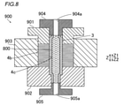
- the laminated core 4b and the shaft 3 are arranged (set) in the hydroforming molding machine 900.
- the hydroforming molding machine 900 includes an upper mold 901 that presses the laminated core 4b from the Z1 side, and a lower mold 902 that presses the laminated core 4b from the Z2 side. Further, the hydroforming molding machine 900 includes a regulation unit 903 that restricts the radial movement of the laminated core 4b from the outside in the radial direction.
- the hydroforming molding machine 900 includes an upper seal portion 904 that seals the end portion of the shaft 3 on the Z1 side and a lower seal portion 905 that seals the end portion of the shaft 3 on the Z2 side.
- the upper seal portion 904 and the lower seal portion 905 are provided with introduction paths 904a and 905a for introducing the liquid 800 inside the shaft 3, respectively.
- step S4 the permanent magnet 5 (see FIG. 1) is inserted into the magnet insertion hole 10a, and a resin material (not shown) is filled in the magnet insertion hole 10a to fix the permanent magnet 5.
- a resin material not shown
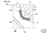
- the rotor 11 of the second embodiment unlike the first embodiment in which the apex 4f of the shaft insertion hole 4c and the bridge portion 10b are arranged so as to overlap each other in the circumferential direction, the side 14g of the shaft insertion hole 14c is the d-axis. It is placed at a position where it overlaps with the circumferential direction.
- the same configuration as that of the first embodiment is illustrated with the same reference numerals as those of the first embodiment, and the description thereof will be omitted.
- the rotary electric machine 200 includes a rotor 11 instead of the rotor 1 of the rotary electric machine 100 of the first embodiment.
- the rotor 11 includes a rotor core 14.
- the rotor core 14 includes a laminated core 14b having a magnet insertion hole 10a.
- the rotor core 14 (laminated core 14b) includes a shaft insertion hole 14c provided in the central portion of the laminated core 14b when viewed from the axial direction of the laminated core 14b (viewed from the Z1 direction side).
- the laminated core 14b is arranged at a position where the side 14g of the shaft insertion hole 14c overlaps with the d-axis of the laminated core 14b in the circumferential direction when viewed from the axial direction. It is configured to be.
- the d-axis means the direction of the magnetic flux created by the magnetic poles in the rotor core 14 (laminated core 14b). In the example shown in FIG. 10, since the magnetic flux passes through the bridge portion 10b, the d-axis is the direction from the rotation axis C toward the bridge portion 10b when viewed from the axial direction.
- each d-axis is formed at a position overlapping with the side 14g of the shaft insertion hole 14c in the circumferential direction.
- the apex 14f of the shaft insertion hole 14c is arranged so as to overlap the position between the magnetic pole forming portions 10 adjacent to each other in the circumferential direction in the circumferential direction.
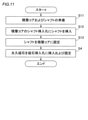
- step S11 a step of preparing the laminated core 14b and the shaft 3 is performed.
- step S11 a core forming step of forming the laminated core 14b is performed so that the side 14g of the shaft insertion hole 14c is arranged at a position overlapping the d-axis of the laminated core 14b in the circumferential direction when viewed from the axial direction. Will be done.
- the core forming step performed in step S11 is an example of the "second core forming step" in the claims.
- step S12 an insertion step of inserting the shaft 3 into the shaft insertion hole 14c is performed.
- the insertion step is performed in the shaft insertion hole 14c of the laminated core 14b arranged at a position where the side 14g of the shaft insertion hole 14c overlaps the d-axis of the laminated core 14b in the circumferential direction when viewed from the axial direction.
- step S13 a fixing step of fixing the shaft 3 to the laminated core 14b is performed.
- the fixing step with the shaft 3 inserted in the shaft insertion hole 14c of the laminated core 14b, the outer peripheral surface 3e of the shaft 3 is formed on the inner circumference of the shaft insertion hole 4c by hydroforming by hydroforming.
- This is a step of fixing the shaft 3 to the laminated core 14b by deforming it into a non-circular shape (regular hexadecagonal shape) along the surface 14i (see FIG. 1).
- the shaft (3) has a laminated core (3) that is expanded by hydroforming by pressurizing the liquid (800) filled inside the shaft (3). It is fixed to 4b, 14b). Further, the shaft insertion holes (4c, 14c) are provided in the central portion of the laminated core (4b, 14b) when viewed from the axial direction of the laminated core (4b, 14b), and a plurality of vertices (4f, 14f) are provided.
- the number of vertices (4f, 14f) and sides (4g, 14g) of the shaft insertion holes (4c, 14c) is an integral multiple of the number of poles, or the number of poles is the number of poles. It is configured to be a number divided by a fraction of the number of poles other than.
- the vertices (4f, 14f) and sides (4g, 14g) of the shaft insertion hole (4c, 14c) is an integral multiple of the number of poles
- the vertices (4f, 14f) are for each of the plurality of poles.
- the rotors (1, 11) it is possible to easily form the rotors (1, 11) so that the 14f) (sides (4g, 14g)) are evenly arranged. Further, when the number of vertices (4f, 14f) and sides (4g, 14g) is the number obtained by dividing the number of poles by the number of poles other than the number of poles, each of the above groups of poles is divided into groups of poles. On the other hand, it is possible to easily form the rotors (1, 11) so that the vertices (4f, 14f) (sides (4g, 14g)) are evenly arranged.
- the rotational displacement of the laminated cores (4b, 14b) with respect to the shaft (3) is more balancedly prevented for each of the plurality of poles or for each of the groups of poles of each divisor. can do.
- the method for manufacturing the rotor (1, 11) is a shaft insertion having a non-circular shape including a plurality of vertices (4f, 14f) when viewed from the axial direction.
- the distance between the vertices (4f, 14f) of the holes (4c, 14c) and the outer peripheral surface (3e) of the shaft (3) is the first distance (L2), and the outer peripheral surface (3e) of the shaft (3) and the shaft.
- the shaft (3) is inserted into the shaft insertion hole (4c, 14c) so that the distance from the side (4g, 14g) of the insertion hole (4c, 14c) is the second distance (L3) smaller than the first distance (L2).
- the inside of the shaft (3) is filled with the shaft (3) inserted into the shaft insertion holes (4c, 14c) of the laminated core (4b, 14b).
- the outer peripheral surface (3e) of the shaft (3) is changed to the inner peripheral surface (4i, 14c) of the shaft insertion hole (4c, 14c) when viewed from the axial direction.
- a fixing step of fixing the shaft (3) to the laminated cores (4b, 14b) by deforming the shaft (3) into a non-circular shape along the 14i) is provided.
- At least a part of the vertices (4f) of the shaft insertion holes (4c) are adjacent to each other in the circumferential direction when viewed from the axial direction.
- a first core forming step of forming a laminated core (4b) is provided so as to be arranged at a position overlapping in the circumferential direction with a bridge portion (10b) provided between the magnet insertion holes (10a).
- the outer peripheral surface (3e) of the shaft (3) first contacts the side (4 g) of the shaft insertion hole (4c) and then contacts the apex (4f) of the shaft insertion hole (4c). Inflate to do.
- the stress applied to the apex (4f) of the shaft insertion hole (4c) is smaller than the stress applied to the side (4g) of the shaft insertion hole (4c). Further, since the width (W1) in the circumferential direction of the bridge portion (10b) is relatively small, the mechanical strength of the bridge portion (10b) is relatively low. Therefore, the stress applied to the bridge portion (10b) having a relatively low mechanical strength can be reduced.
- the laminated core (4b) includes a plurality of magnetic pole forming portions (10) forming magnetic poles. Further, in the first core forming step, when viewed from the axial direction, at least a pair of apex (4f) of the shaft insertion holes (4c) are adjacent to each other in the circumferential direction in each of the plurality of magnetic pole forming portions (10). It is provided between the magnet insertion holes (10a) of the magnet insertion holes (10a) and connects the radial outer portion (4l) of the laminated core (4b) and the radial inner portion (4h) of the laminated core (4b).
- the stress of hydroforming applied to the apex (4f) is relatively small, so that the stress of hydroforming applied to the bridge portion (10b) provided in each of the plurality of magnetic pole forming portions (10) can be reduced.
- the side (14 g) of the shaft insertion hole (14c) is arranged at a position overlapping the d-axis of the laminated core (14b) in the circumferential direction when viewed from the axial direction.
- a second core forming step for forming the laminated core (14b) is further provided.
- the side (14 g) of the shaft insertion hole (14c) is arranged radially inside the apex (14f) of the shaft insertion hole (14c).
- the side (14 g) of the shaft insertion hole (14c) is arranged relatively inward in the radial direction, so that the q-axis adjacent to one side in the circumferential direction of the d-axis is located on the other side in the circumferential direction of the d-axis. It is possible to increase the width of the magnetic path through which the magnetic flux flowing in the q-axis adjacent to is passed. As a result, the magnetic flux can be easily flowed, so that it is possible to prevent the motor output from being reduced due to the decrease in the magnetic flux.
- the shaft insertion holes (4c, 14c) have an example of having a regular polygonal shape, but the present invention is not limited to this.
- the shaft insertion hole may have a polygonal shape that is not a regular polygon.
- the shaft insertion hole may have a shape that is not polygonal and has an apex.
- the number of vertices (4f, 14f) and sides (4g, 14g) of the shaft insertion holes (4c, 14c) is an integral multiple of the number of poles.
- the present invention is not limited to this.
- the number of vertices and sides of the shaft insertion hole may be a number obtained by dividing the number of poles by a divisor of the number of poles other than the number of poles (four in the first and second embodiments).
- the number of vertices (4f, 14f) and sides (4g, 14g) of the shaft insertion holes (4c, 14c) is twice the number of poles.
- the present invention is not limited to this.
- the number of vertices and sides of the shaft insertion hole may be equal to the number of poles.
- the apex 4f of the shaft insertion hole 4c is arranged at a position where it overlaps with all the bridge portions 10b in the circumferential direction is shown, but the present invention is not limited to this.
- the apex 4f of the shaft insertion hole 4c may be arranged at a position where it overlaps with a part of the eight bridge portions 10b in the circumferential direction.
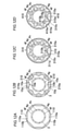
- the magnetic pole forming portion 10 is composed of a pair of magnet insertion holes 10a and a bridge portion 10b adjacent to each other in the circumferential direction, but the present invention is limited to this. I can't.
- the magnetic pole forming portion 110 includes only one magnet insertion hole 110a extending in the circumferential direction.
- the bridge portion 110b is between the magnet insertion holes 110a adjacent to each other in the circumferential direction.
- the apex 4f of the shaft insertion hole 4c is arranged at a position overlapping with all the bridge portions 110b in the circumferential direction.
- the side 14g of the shaft insertion hole 14c is arranged at a position overlapping with the d-axis (direction from the rotation axis C toward the center of the circumferential direction of the magnet insertion hole 110a) in the circumferential direction.
- the magnetic pole forming portion 210 has a pair of magnet insertion holes 10a, a bridge portion 10b between the pair of magnet insertion holes 10a, and a pair of magnet insertion holes 10a in the radial direction. It includes a magnet insertion hole 210a extending in the circumferential direction on the outside. As shown in FIG. 12B, the apex 4f of the shaft insertion hole 4c is arranged at a position overlapping with all the bridge portions 10b in the circumferential direction. Further, as shown in FIG.
- the side 14g of the shaft insertion hole 14c is arranged at a position overlapping in the circumferential direction with the d-axis (direction from the rotation axis C toward the center of the bridge portion 10b and the magnet insertion hole 210a in the circumferential direction). ing.
- the magnetic pole forming portion 310 includes a pair of magnet insertion holes 310a adjacent to each other in the circumferential direction and a magnet insertion hole 311a extending in the circumferential direction on the radial outer side of the pair of magnet insertion holes 310a. And include.
- a flux barrier 310c is provided in the bridge portion 310b between the magnet insertion holes 310a.
- the apex 4f of the shaft insertion hole 4c is arranged at a position where it overlaps with all the bridge portions 310b (flux barrier 310c) in the circumferential direction. Further, as shown in FIG.
- the side 14g of the shaft insertion hole 14c is arranged at a position overlapping in the circumferential direction with the d-axis (direction from the rotation axis C toward the center of the bridge portion 310b and the magnet insertion hole 311a in the circumferential direction). ing.
- the magnetic pole forming portions 410 are provided so as to be adjacent to each other in the circumferential direction on the radial outer side of the pair of magnet insertion holes 310a, the bridge portion 310b, and the pair of magnet insertion holes 310a. It includes a pair of magnet insertion holes 410a to be formed. A bridge portion 410b is provided between the pair of magnet insertion holes 410a. As shown in FIG. 12D, the apex 4f of the shaft insertion hole 4c is arranged at a position where it overlaps with all the bridge portions 310b (bridge portions 410b) in the circumferential direction. Further, as shown in FIG. 13D, the side 14g of the shaft insertion hole 14c is arranged at a position overlapping with the d-axis (direction from the rotation axis C toward the bridge portion 310b and the bridge portion 410b) in the circumferential direction.
- the step of inserting the permanent magnet 5 into the magnet insertion hole 10a after hydroforming is shown, but the present invention is not limited to this. Hydroforming may be performed after the permanent magnet 5 is inserted into the magnet insertion hole 10a.
Landscapes
- Engineering & Computer Science (AREA)
- Power Engineering (AREA)
- Mechanical Engineering (AREA)
- Manufacturing & Machinery (AREA)
- Physics & Mathematics (AREA)
- Fluid Mechanics (AREA)
- Iron Core Of Rotating Electric Machines (AREA)
- Permanent Field Magnets Of Synchronous Machinery (AREA)
- Manufacture Of Motors, Generators (AREA)
Priority Applications (4)
| Application Number | Priority Date | Filing Date | Title |
|---|---|---|---|
| JP2022536132A JP7452658B2 (ja) | 2020-07-16 | 2021-03-22 | ロータの製造方法およびロータ |
| US17/925,457 US20230188015A1 (en) | 2020-07-16 | 2021-03-22 | Method for manufacturing rotor and rotor |
| CN202180045536.3A CN115989623A (zh) | 2020-07-16 | 2021-03-22 | 转子的制造方法和转子 |
| EP21843279.7A EP4152576A4 (de) | 2020-07-16 | 2021-03-22 | Rotorherstellungsverfahren und rotor |
Applications Claiming Priority (2)
| Application Number | Priority Date | Filing Date | Title |
|---|---|---|---|
| JP2020121866 | 2020-07-16 | ||
| JP2020-121866 | 2020-07-16 |
Publications (1)
| Publication Number | Publication Date |
|---|---|
| WO2022014100A1 true WO2022014100A1 (ja) | 2022-01-20 |
Family
ID=79554675
Family Applications (1)
| Application Number | Title | Priority Date | Filing Date |
|---|---|---|---|
| PCT/JP2021/011728 Ceased WO2022014100A1 (ja) | 2020-07-16 | 2021-03-22 | ロータの製造方法およびロータ |
Country Status (5)
| Country | Link |
|---|---|
| US (1) | US20230188015A1 (de) |
| EP (1) | EP4152576A4 (de) |
| JP (1) | JP7452658B2 (de) |
| CN (1) | CN115989623A (de) |
| WO (1) | WO2022014100A1 (de) |
Families Citing this family (1)
| Publication number | Priority date | Publication date | Assignee | Title |
|---|---|---|---|---|
| CN119973578B (zh) * | 2025-04-17 | 2025-07-25 | 东方电气集团东方电机有限公司 | 一种大尺寸薄壁筒成型方法 |
Citations (4)
| Publication number | Priority date | Publication date | Assignee | Title |
|---|---|---|---|---|
| JPS53149608A (en) * | 1978-05-18 | 1978-12-27 | Mitsubishi Electric Corp | Manufacture method of laminated iron core |
| JP2001268858A (ja) | 2000-03-17 | 2001-09-28 | Toyota Autom Loom Works Ltd | モータ用ロータ、電動圧縮機及びモータ用ロータの製造方法 |
| US20140097711A1 (en) * | 2012-10-05 | 2014-04-10 | Larry Kubes | One piece rotor hub/shaft for an electric machine and method |
| JP2019075877A (ja) * | 2017-10-13 | 2019-05-16 | トヨタ自動車株式会社 | 回転電機ロータの製造方法及び回転電機ロータ |
Family Cites Families (5)
| Publication number | Priority date | Publication date | Assignee | Title |
|---|---|---|---|---|
| DE10300148A1 (de) * | 2002-01-07 | 2003-08-28 | Arvinmeritor Technology Llc | Verfahren zur Herstellung einer Antriebswelle |
| JP5244721B2 (ja) * | 2009-07-07 | 2013-07-24 | トヨタ自動車株式会社 | 回転電機のロータ |
| KR101271950B1 (ko) * | 2011-12-26 | 2013-06-07 | 재단법인 포항산업과학연구원 | 중공형 모터축 및 이를 포함하는 모터장치 |
| DE102018122977B4 (de) * | 2018-09-19 | 2026-02-12 | Muhr Und Bender Kg | Wellenanordnung |
| DE102018218322A1 (de) * | 2018-10-26 | 2020-04-30 | Volkswagen Aktiengesellschaft | Verfahren und Werkzeug zur Herstellung eines Rotors für eine elektrische Maschine |
-
2021
- 2021-03-22 JP JP2022536132A patent/JP7452658B2/ja active Active
- 2021-03-22 CN CN202180045536.3A patent/CN115989623A/zh active Pending
- 2021-03-22 EP EP21843279.7A patent/EP4152576A4/de not_active Withdrawn
- 2021-03-22 WO PCT/JP2021/011728 patent/WO2022014100A1/ja not_active Ceased
- 2021-03-22 US US17/925,457 patent/US20230188015A1/en not_active Abandoned
Patent Citations (4)
| Publication number | Priority date | Publication date | Assignee | Title |
|---|---|---|---|---|
| JPS53149608A (en) * | 1978-05-18 | 1978-12-27 | Mitsubishi Electric Corp | Manufacture method of laminated iron core |
| JP2001268858A (ja) | 2000-03-17 | 2001-09-28 | Toyota Autom Loom Works Ltd | モータ用ロータ、電動圧縮機及びモータ用ロータの製造方法 |
| US20140097711A1 (en) * | 2012-10-05 | 2014-04-10 | Larry Kubes | One piece rotor hub/shaft for an electric machine and method |
| JP2019075877A (ja) * | 2017-10-13 | 2019-05-16 | トヨタ自動車株式会社 | 回転電機ロータの製造方法及び回転電機ロータ |
Non-Patent Citations (1)
| Title |
|---|
| See also references of EP4152576A4 |
Also Published As
| Publication number | Publication date |
|---|---|
| EP4152576A4 (de) | 2023-11-08 |
| CN115989623A (zh) | 2023-04-18 |
| US20230188015A1 (en) | 2023-06-15 |
| JP7452658B2 (ja) | 2024-03-19 |
| EP4152576A1 (de) | 2023-03-22 |
| JPWO2022014100A1 (de) | 2022-01-20 |
Similar Documents
| Publication | Publication Date | Title |
|---|---|---|
| CN104937815B (zh) | 永磁体式旋转电机 | |
| JP6274475B2 (ja) | 回転子、回転電機および回転子の製造方法 | |
| US8878410B2 (en) | Rotor with reinforcing portions for an electric rotating machine | |
| JP7234333B2 (ja) | 2分節擬似ハルバッハモータの回転子 | |
| US12519353B2 (en) | Rotor core with plurality of permanent magnets and magnet holes with bridges between magnets/magnet holes | |
| CN103095088A (zh) | 旋转电机 | |
| WO2021060209A1 (ja) | 回転電機の回転子 | |
| WO2018131393A1 (ja) | 回転電機用ロータ | |
| US20230198324A1 (en) | Rotor for rotary electric machine | |
| JP2018198534A (ja) | 回転電機 | |
| US12519356B2 (en) | Rotor and rotating electric machine | |
| JP7452658B2 (ja) | ロータの製造方法およびロータ | |
| WO2019044206A1 (ja) | 回転電機 | |
| WO2023276680A1 (ja) | 回転電機 | |
| JP7528591B2 (ja) | ロータおよびロータの製造方法 | |
| US12573900B2 (en) | Rotor and rotating electric machine | |
| JP7718258B2 (ja) | ロータ及び回転電機 | |
| WO2024120543A1 (zh) | 电机转子和电机转子的制作方法 | |
| JP2014082836A (ja) | ロータと、それを備える回転電機 | |
| JP2022163299A (ja) | モータ | |
| US20250211042A1 (en) | Rotating electric machine core and rotating electric machine | |
| US20240186849A1 (en) | Rotor of rotary electric machine and method for manufacturing rotor | |
| JP4459886B2 (ja) | ステータおよびモータ | |
| JP2021078241A (ja) | ロータの製造方法およびロータ | |
| US20240097512A1 (en) | Rotor and rotating electric machine |
Legal Events
| Date | Code | Title | Description |
|---|---|---|---|
| 121 | Ep: the epo has been informed by wipo that ep was designated in this application |
Ref document number: 21843279 Country of ref document: EP Kind code of ref document: A1 |
|
| ENP | Entry into the national phase |
Ref document number: 2022536132 Country of ref document: JP Kind code of ref document: A |
|
| ENP | Entry into the national phase |
Ref document number: 2021843279 Country of ref document: EP Effective date: 20221213 |
|
| NENP | Non-entry into the national phase |
Ref country code: DE |